EP3300828A1 - Inverted directed energy deposition - Google Patents
Inverted directed energy deposition Download PDFInfo
- Publication number
- EP3300828A1 EP3300828A1 EP17187191.6A EP17187191A EP3300828A1 EP 3300828 A1 EP3300828 A1 EP 3300828A1 EP 17187191 A EP17187191 A EP 17187191A EP 3300828 A1 EP3300828 A1 EP 3300828A1
- Authority
- EP
- European Patent Office
- Prior art keywords
- substrate
- molten pool
- component
- computing device
- stream
- Prior art date
- Legal status (The legal status is an assumption and is not a legal conclusion. Google has not performed a legal analysis and makes no representation as to the accuracy of the status listed.)
- Pending
Links
Images



Classifications
-
- B—PERFORMING OPERATIONS; TRANSPORTING
- B23—MACHINE TOOLS; METAL-WORKING NOT OTHERWISE PROVIDED FOR
- B23K—SOLDERING OR UNSOLDERING; WELDING; CLADDING OR PLATING BY SOLDERING OR WELDING; CUTTING BY APPLYING HEAT LOCALLY, e.g. FLAME CUTTING; WORKING BY LASER BEAM
- B23K26/00—Working by laser beam, e.g. welding, cutting or boring
- B23K26/34—Laser welding for purposes other than joining
- B23K26/342—Build-up welding
-
- B—PERFORMING OPERATIONS; TRANSPORTING
- B22—CASTING; POWDER METALLURGY
- B22F—WORKING METALLIC POWDER; MANUFACTURE OF ARTICLES FROM METALLIC POWDER; MAKING METALLIC POWDER; APPARATUS OR DEVICES SPECIALLY ADAPTED FOR METALLIC POWDER
- B22F10/00—Additive manufacturing of workpieces or articles from metallic powder
- B22F10/20—Direct sintering or melting
- B22F10/25—Direct deposition of metal particles, e.g. direct metal deposition [DMD] or laser engineered net shaping [LENS]
-
- B—PERFORMING OPERATIONS; TRANSPORTING
- B22—CASTING; POWDER METALLURGY
- B22F—WORKING METALLIC POWDER; MANUFACTURE OF ARTICLES FROM METALLIC POWDER; MAKING METALLIC POWDER; APPARATUS OR DEVICES SPECIALLY ADAPTED FOR METALLIC POWDER
- B22F10/00—Additive manufacturing of workpieces or articles from metallic powder
- B22F10/30—Process control
- B22F10/36—Process control of energy beam parameters
-
- B—PERFORMING OPERATIONS; TRANSPORTING
- B22—CASTING; POWDER METALLURGY
- B22F—WORKING METALLIC POWDER; MANUFACTURE OF ARTICLES FROM METALLIC POWDER; MAKING METALLIC POWDER; APPARATUS OR DEVICES SPECIALLY ADAPTED FOR METALLIC POWDER
- B22F12/00—Apparatus or devices specially adapted for additive manufacturing; Auxiliary means for additive manufacturing; Combinations of additive manufacturing apparatus or devices with other processing apparatus or devices
- B22F12/30—Platforms or substrates
- B22F12/33—Platforms or substrates translatory in the deposition plane
-
- B—PERFORMING OPERATIONS; TRANSPORTING
- B22—CASTING; POWDER METALLURGY
- B22F—WORKING METALLIC POWDER; MANUFACTURE OF ARTICLES FROM METALLIC POWDER; MAKING METALLIC POWDER; APPARATUS OR DEVICES SPECIALLY ADAPTED FOR METALLIC POWDER
- B22F12/00—Apparatus or devices specially adapted for additive manufacturing; Auxiliary means for additive manufacturing; Combinations of additive manufacturing apparatus or devices with other processing apparatus or devices
- B22F12/30—Platforms or substrates
- B22F12/37—Rotatable
-
- B—PERFORMING OPERATIONS; TRANSPORTING
- B22—CASTING; POWDER METALLURGY
- B22F—WORKING METALLIC POWDER; MANUFACTURE OF ARTICLES FROM METALLIC POWDER; MAKING METALLIC POWDER; APPARATUS OR DEVICES SPECIALLY ADAPTED FOR METALLIC POWDER
- B22F12/00—Apparatus or devices specially adapted for additive manufacturing; Auxiliary means for additive manufacturing; Combinations of additive manufacturing apparatus or devices with other processing apparatus or devices
- B22F12/90—Means for process control, e.g. cameras or sensors
-
- B—PERFORMING OPERATIONS; TRANSPORTING
- B23—MACHINE TOOLS; METAL-WORKING NOT OTHERWISE PROVIDED FOR
- B23K—SOLDERING OR UNSOLDERING; WELDING; CLADDING OR PLATING BY SOLDERING OR WELDING; CUTTING BY APPLYING HEAT LOCALLY, e.g. FLAME CUTTING; WORKING BY LASER BEAM
- B23K15/00—Electron-beam welding or cutting
- B23K15/002—Devices involving relative movement between electron beam and workpiece
-
- B—PERFORMING OPERATIONS; TRANSPORTING
- B23—MACHINE TOOLS; METAL-WORKING NOT OTHERWISE PROVIDED FOR
- B23K—SOLDERING OR UNSOLDERING; WELDING; CLADDING OR PLATING BY SOLDERING OR WELDING; CUTTING BY APPLYING HEAT LOCALLY, e.g. FLAME CUTTING; WORKING BY LASER BEAM
- B23K15/00—Electron-beam welding or cutting
- B23K15/0046—Welding
- B23K15/0086—Welding welding for purposes other than joining, e.g. build-up welding
-
- B—PERFORMING OPERATIONS; TRANSPORTING
- B23—MACHINE TOOLS; METAL-WORKING NOT OTHERWISE PROVIDED FOR
- B23K—SOLDERING OR UNSOLDERING; WELDING; CLADDING OR PLATING BY SOLDERING OR WELDING; CUTTING BY APPLYING HEAT LOCALLY, e.g. FLAME CUTTING; WORKING BY LASER BEAM
- B23K26/00—Working by laser beam, e.g. welding, cutting or boring
- B23K26/02—Positioning or observing the workpiece, e.g. with respect to the point of impact; Aligning, aiming or focusing the laser beam
- B23K26/03—Observing, e.g. monitoring, the workpiece
- B23K26/032—Observing, e.g. monitoring, the workpiece using optical means
-
- B—PERFORMING OPERATIONS; TRANSPORTING
- B23—MACHINE TOOLS; METAL-WORKING NOT OTHERWISE PROVIDED FOR
- B23K—SOLDERING OR UNSOLDERING; WELDING; CLADDING OR PLATING BY SOLDERING OR WELDING; CUTTING BY APPLYING HEAT LOCALLY, e.g. FLAME CUTTING; WORKING BY LASER BEAM
- B23K26/00—Working by laser beam, e.g. welding, cutting or boring
- B23K26/08—Devices involving relative movement between laser beam and workpiece
-
- B—PERFORMING OPERATIONS; TRANSPORTING
- B23—MACHINE TOOLS; METAL-WORKING NOT OTHERWISE PROVIDED FOR
- B23K—SOLDERING OR UNSOLDERING; WELDING; CLADDING OR PLATING BY SOLDERING OR WELDING; CUTTING BY APPLYING HEAT LOCALLY, e.g. FLAME CUTTING; WORKING BY LASER BEAM
- B23K26/00—Working by laser beam, e.g. welding, cutting or boring
- B23K26/14—Working by laser beam, e.g. welding, cutting or boring using a fluid stream, e.g. a jet of gas, in conjunction with the laser beam; Nozzles therefor
- B23K26/144—Working by laser beam, e.g. welding, cutting or boring using a fluid stream, e.g. a jet of gas, in conjunction with the laser beam; Nozzles therefor the fluid stream containing particles, e.g. powder
-
- B—PERFORMING OPERATIONS; TRANSPORTING
- B33—ADDITIVE MANUFACTURING TECHNOLOGY
- B33Y—ADDITIVE MANUFACTURING, i.e. MANUFACTURING OF THREE-DIMENSIONAL [3D] OBJECTS BY ADDITIVE DEPOSITION, ADDITIVE AGGLOMERATION OR ADDITIVE LAYERING, e.g. BY 3D PRINTING, STEREOLITHOGRAPHY OR SELECTIVE LASER SINTERING
- B33Y10/00—Processes of additive manufacturing
-
- B—PERFORMING OPERATIONS; TRANSPORTING
- B33—ADDITIVE MANUFACTURING TECHNOLOGY
- B33Y—ADDITIVE MANUFACTURING, i.e. MANUFACTURING OF THREE-DIMENSIONAL [3D] OBJECTS BY ADDITIVE DEPOSITION, ADDITIVE AGGLOMERATION OR ADDITIVE LAYERING, e.g. BY 3D PRINTING, STEREOLITHOGRAPHY OR SELECTIVE LASER SINTERING
- B33Y30/00—Apparatus for additive manufacturing; Details thereof or accessories therefor
-
- F—MECHANICAL ENGINEERING; LIGHTING; HEATING; WEAPONS; BLASTING
- F01—MACHINES OR ENGINES IN GENERAL; ENGINE PLANTS IN GENERAL; STEAM ENGINES
- F01D—NON-POSITIVE DISPLACEMENT MACHINES OR ENGINES, e.g. STEAM TURBINES
- F01D5/00—Blades; Blade-carrying members; Heating, heat-insulating, cooling or antivibration means on the blades or the members
- F01D5/005—Repairing methods or devices
-
- B—PERFORMING OPERATIONS; TRANSPORTING
- B22—CASTING; POWDER METALLURGY
- B22F—WORKING METALLIC POWDER; MANUFACTURE OF ARTICLES FROM METALLIC POWDER; MAKING METALLIC POWDER; APPARATUS OR DEVICES SPECIALLY ADAPTED FOR METALLIC POWDER
- B22F10/00—Additive manufacturing of workpieces or articles from metallic powder
- B22F10/50—Treatment of workpieces or articles during build-up, e.g. treatments applied to fused layers during build-up
-
- B—PERFORMING OPERATIONS; TRANSPORTING
- B22—CASTING; POWDER METALLURGY
- B22F—WORKING METALLIC POWDER; MANUFACTURE OF ARTICLES FROM METALLIC POWDER; MAKING METALLIC POWDER; APPARATUS OR DEVICES SPECIALLY ADAPTED FOR METALLIC POWDER
- B22F10/00—Additive manufacturing of workpieces or articles from metallic powder
- B22F10/60—Treatment of workpieces or articles after build-up
- B22F10/66—Treatment of workpieces or articles after build-up by mechanical means
-
- B—PERFORMING OPERATIONS; TRANSPORTING
- B22—CASTING; POWDER METALLURGY
- B22F—WORKING METALLIC POWDER; MANUFACTURE OF ARTICLES FROM METALLIC POWDER; MAKING METALLIC POWDER; APPARATUS OR DEVICES SPECIALLY ADAPTED FOR METALLIC POWDER
- B22F12/00—Apparatus or devices specially adapted for additive manufacturing; Auxiliary means for additive manufacturing; Combinations of additive manufacturing apparatus or devices with other processing apparatus or devices
- B22F12/50—Means for feeding of material, e.g. heads
- B22F12/55—Two or more means for feeding material
-
- B—PERFORMING OPERATIONS; TRANSPORTING
- B22—CASTING; POWDER METALLURGY
- B22F—WORKING METALLIC POWDER; MANUFACTURE OF ARTICLES FROM METALLIC POWDER; MAKING METALLIC POWDER; APPARATUS OR DEVICES SPECIALLY ADAPTED FOR METALLIC POWDER
- B22F5/00—Manufacture of workpieces or articles from metallic powder characterised by the special shape of the product
- B22F5/009—Manufacture of workpieces or articles from metallic powder characterised by the special shape of the product of turbine components other than turbine blades
-
- B—PERFORMING OPERATIONS; TRANSPORTING
- B22—CASTING; POWDER METALLURGY
- B22F—WORKING METALLIC POWDER; MANUFACTURE OF ARTICLES FROM METALLIC POWDER; MAKING METALLIC POWDER; APPARATUS OR DEVICES SPECIALLY ADAPTED FOR METALLIC POWDER
- B22F5/00—Manufacture of workpieces or articles from metallic powder characterised by the special shape of the product
- B22F5/04—Manufacture of workpieces or articles from metallic powder characterised by the special shape of the product of turbine blades
-
- F—MECHANICAL ENGINEERING; LIGHTING; HEATING; WEAPONS; BLASTING
- F05—INDEXING SCHEMES RELATING TO ENGINES OR PUMPS IN VARIOUS SUBCLASSES OF CLASSES F01-F04
- F05D—INDEXING SCHEME FOR ASPECTS RELATING TO NON-POSITIVE-DISPLACEMENT MACHINES OR ENGINES, GAS-TURBINES OR JET-PROPULSION PLANTS
- F05D2230/00—Manufacture
- F05D2230/20—Manufacture essentially without removing material
- F05D2230/22—Manufacture essentially without removing material by sintering
-
- Y—GENERAL TAGGING OF NEW TECHNOLOGICAL DEVELOPMENTS; GENERAL TAGGING OF CROSS-SECTIONAL TECHNOLOGIES SPANNING OVER SEVERAL SECTIONS OF THE IPC; TECHNICAL SUBJECTS COVERED BY FORMER USPC CROSS-REFERENCE ART COLLECTIONS [XRACs] AND DIGESTS
- Y02—TECHNOLOGIES OR APPLICATIONS FOR MITIGATION OR ADAPTATION AGAINST CLIMATE CHANGE
- Y02P—CLIMATE CHANGE MITIGATION TECHNOLOGIES IN THE PRODUCTION OR PROCESSING OF GOODS
- Y02P10/00—Technologies related to metal processing
- Y02P10/25—Process efficiency
Definitions
- the present disclosure generally relates to technique for forming a component using directed energy deposition.
- Additive manufacturing for example, directed energy deposition techniques, may be used to fabricate a component having a predetermined three-dimensional structure, typically by depositing material layer-by-layer or volume-by-volume to form the structure, rather than by removing material from an existing component. Additive manufacturing may be advantageous in many situations, such as rapid prototyping, forming components with complex three-dimensional structures, or the like.
- a method comprising controlling, by a computing device, a material source to direct a stream of solid material to a molten pool in an upward direction defined with respect to gravity, wherein a substrate defines a surface having the molten pool, wherein the molten pool faces a downward direction defined with respect to gravity, wherein the material combines with the molten pool to form a deposited volume of a plurality of deposited volumes, and wherein the plurality of deposited volumes defines a component.
- the method may further comprise controlling, by the computing device, a build platform configured to hold the substrate, to orient the substrate to allow undeposited material from the stream of solid material to substantially fall away from the substrate in a downward direction defined with respect to gravity.
- the method may further comprise controlling, by the computing device, the build platform to move the substrate to cause undeposited material from the stream of solid material to substantially fall away from the substrate in the downward direction defined with respect to gravity.
- the method may further comprise controlling, by the computing device, based on a digital representation of the component, an energy source to direct an energy beam at the substrate to form the molten pool.
- the surface may comprise a chamber surface at which the molten pool is formed.
- the control of the energy source may comprise advancing the molten pool along a path on the surface.
- the control of the material source may comprise directing the stream of solid material to the advancing molten pool along the path to form the plurality of deposited volumes.
- the plurality of deposited volumes may define a chamber comprising the chamber surface.
- the chamber may be substantially free of undeposited material from the stream of solid material.
- the method may further comprise controlling, by the computing device, the material source and the energy source to define a build direction of the component in the downward direction.
- the method may further comprise controlling, by the computing device, an imaging device to image one or more of the substrate, the molten pool, and the stream of solid material.
- Computer-readable instructions executable by a computing device may be provided that cause the computer to perform the aforesaid method.
- the computer-readable instructions may be encoded on a computer-readable medium.
- a system comprising: a material source; a substrate having a molten pool on a surface of the substrate, wherein the molten pool faces a downward direction defined with respect to gravity; and a computing device; wherein the computing device is configured to: control the material source to direct a stream of solid material to the molten pool in an upward direction defined with respect to gravity, wherein the material combines with the molten pool to form a deposited volume of a plurality of deposited volumes, and wherein the plurality of deposited volumes defines a component.
- the system may further comprise a build platform configured to hold the substrate.
- the computing device may be further configured to control the build platform to orient the substrate to allow undeposited material from the stream of solid material to substantially fall away from the substrate in a direction defined with respect to gravity.
- the computing device may be further configured to control the build platform to move the substrate to cause undeposited material from the stream of solid material to substantially fall away from the substrate in the direction defined with respect to gravity.
- the system may further comprise an energy source.
- the computing device may be configured to control, based on a digital representation of the component, the energy source to direct an energy beam at the substrate to form the molten pool.
- the surface may comprise a chamber surface at which the molten pool is formed.
- the computing device may be configured to control the energy device to advance the molten pool along a path on the surface.
- the computing device may be configured to control the material source to direct the stream of solid material to the advancing molten pool along the path to form the plurality of deposited volumes.
- the plurality of deposited volumes may define a chamber comprising the chamber surface.
- the chamber may be substantially free of undeposited material from the stream of solid material.
- the computing device may be configured to control the material source and the energy source to define a build direction of the component in the downward direction.
- the system may further comprise an imaging device.
- the computing device may be configured to control the imaging device to image one or more of the substrate, the molten pool, and the stream of solid material.
- example techniques for directed energy deposition may include directing an energy beam at a region of a component to form an advancing molten pool and delivering material to the advancing molten pool, resulting in combining of the material and a substrate of the component by sintering or melting, to form a deposited volume of a plurality of deposited volumes.
- the plurality of deposited volumes may define the component, for example, a volume of the component defining a chamber.
- uncombined, unmelted, or otherwise undeposited material from the stream may accumulate within depressions, chambers, or voids on or within components fabricated by additive manufacturing as successive layers are deposited. If the accumulated material is not removed, the finished article may define chambers that include residual material. Such residual material may be undesirable, for example, because they may change the mass or the mass distribution of the component, may lead to unintended vibration frequencies during operation of the component, may block channels or openings, or may result in an audible sound such as rustling or rattling.
- an example system may use inverted directed energy deposition.
- the example system may include a computing device that controls a material source to direct a stream of solid material to a molten pool in an upward direction defined with respect to gravity.
- the material may substantially combine with the molten pool to form a deposited volume of a plurality of deposited volumes.
- the plurality of deposited volumes defines a component. Undeposited material from the stream of solid material may fall away from the substrate in a downward direction defined with respect to gravity, so that the undeposited material does not accumulate within a chamber defined by the plurality of deposited volumes.
- systems and techniques are provided to fabricate components defining chambers that may be substantially free of undeposited or residual material.
- a downward direction according to the disclosure may include any direction directly towards or inclined towards a gravitational force.
- a direct downward direction may be parallel to the direction of ambient gravity.
- An inclined downward direction may point along an inclined axis greater than about 1 degrees, or greater than about 30 degrees, or less than about 60 degrees, or less than about 90 degrees relative to the direction of ambient gravity.
- An upward direction may include a direction directly away from or against the gravitational force, or inclined away from or against ambient gravity.
- a direct upward direction may be antiparallel to the direction of ambient gravity.
- An inclined upward direction may point along an inclined axis greater than about 1 degrees, or greater than about 30 degrees, or less than about 60 degrees, or less than about 90 degrees relative to the direction against ambient gravity. In this way, as used here, downward and upward may be defined with respect to the direction of gravity.
- FIG. 1A is a conceptual and schematic block diagram illustrating an example system 10 for directed energy deposition of a component 12.
- Example system 10 includes a computing device 14, a directed energy deposition tool 16, a controller 20, a material source 22, an energy source 24, and an imaging device 26.
- Component 12 may include any structure which may be fabricated using directed energy deposition.
- component 12 may include a gas turbine engine component, such as, a turbine blade, a turbine vane, a shroud, a seal fin, a platform, an airfoil, or the like.
- component 12 may include structural features and geometry of any size, shape, or both.
- component 12 may include a metal or alloy substrate.
- component 12 may include one or more of nickel, cobalt, nickel alloys, cobalt alloys, superalloys, or their combinations.
- Component 12 may include single crystal or polycrystalline materials.
- component 12 may include magnesium based, nickel based, ferrous, and titanium alloys.
- An example of a single crystal nickel based alloy is CMSX-4.
- the alloys may include alloying additions including at least one of Mn, Mg, Cr, Si, Co, W, Ta, Al, Ti, Hf, Re, Mo, Ni, Fe, B, Nb, V, C, and Y.
- component 12 may include composite materials.
- component 12 defines a depression, aperture, or void (collectively, "chamber").
- the chamber may include channels, for example, cooling channels; apertures, for example, cooling holes or impingement apertures; voids for reducing weight; apertures that may be used to join component 12 to another component, for example, by filling with a joining or brazing composition or a mechanical fastener; or other voids or regions free of material.
- Computing device 14 may control system 10 for fabricating component 12.
- Computing device 14 may include any of a wide range of devices, including computer servers, desktop computers, notebook (i.e., laptop) computers, tablet computers, and the like.
- computing device 14 may include a processor.
- the processor may include one or more microprocessors, digital signal processors (DSP), application specific integrated circuits (ASIC), field programmable gate arrays (FPGA), or other digital logic circuitry.
- DSP digital signal processors
- ASIC application specific integrated circuits
- FPGA field programmable gate arrays
- Computing device 14 may be communicatively coupled to directed energy deposition tool 16 and configured to control directed energy deposition tool 16.
- computing device 14 may generate or store a digital representation 12a of component 12.
- digital representation 12a may include a digital representation of chamber 18a generally corresponding to chamber 18 of component 12.
- computing device 14 may control directed energy deposition tool 16 to fabricate component 12 based on digital representation 12a.
- directed energy deposition tool 16 may include a controller 20 for controlling one or more of material source 22, energy source 24, and imaging device 26.
- Computing device 14 may send control signals to controller 20 for controlling direct energy deposition tool 16.
- computing device 14 may send operational signals to and receive status signals from controller 20 to control and monitor the operation of directed energy deposition tool 16.
- computing device 14 may not control directed energy deposition tool 16, and controller 20 may be configured to receive signals indicative of digital representation 12a from computing device 14 and to control directed energy deposition tool 16 based on digital representation 12a to fabricate component 12.
- additive manufacturing tool 16 may not include controller 20, and, instead of controller 20, computing device 14 may control one or more of material source 22, energy source 24, imaging device 26, and build platform 15 according to examples described with reference to controller 20.
- system 10 may include a build platform 15 to hold component 12.
- Build platform 15 may include one or more of an adhesive layer, an adhesive surface or pad, a coating, build tape, platform tape, kapton tape, blue tape, hooks, straps, brackets, or other fasteners to hold component 12 substantially stationary relative to build platform 15.
- component 12 may be bonded to build platform 15 by a thin layer of fused or molten material adhering to a surface of build platform 15.
- build platform 15 continues to hold partially or completely fabricated component 12 in various configurations, including upwards, downwards, sideways, or any other orientation with respect to gravity, until component 12 is detached, for example, by physical, mechanical, or chemical separation from build platform 15.
- system 10 may not include build platform 15, and controller 20 may control the position and orientation of component 12, for example, by controlling an industrial robot, a movable platform, or a multi-axis stage supporting component 12.
- one or both of at least partially fabricated component 12 and part or whole of build platform 15 may be considered to form a substrate 13.
- directed energy deposition tool 16 may deposit material on substrate 13 to eventually fabricate component 12, for example, held on build platform 15.
- substrate 13 may include a base component on which component 12 is further formed. The base component may be formed of any material to which material may be added using directed energy deposition or material addition.
- substrate 13 may include a damaged component on which component 12 is fabricated as part of a repair region, repair volume, or repair structure.
- the base or damaged component may be fabricated using any suitable technique for manufacturing metal or alloy components.
- the base or damaged component may be fabricated using at least one of casting, molding, stamping, cutting, punching, milling, etching, welding, or other metal working techniques.
- the base or damaged component itself may be fabricated using directed energy deposition.
- example systems and techniques described herein may be used to repair damage to various gas turbine engine components, for example, by restoring damaged components so that they conform to predetermined specifications.
- controller 20 may control, based on digital representation 12a, energy source 24 to direct an energy beam 28 at substrate 13, for example, at a surface of substrate 13.
- Energy source 24 may include a power source such as a laser source or an electron beam source (not shown) and output the energy beam 28 directed at substrate 13.
- energy beam 28 may include a laser beam, a plasma, light, electromagnetic radiation, an electron beam, or another form of focused energy absorbable by the material of component 12, the material to be added to component 12, or both, and sufficiently strong to heat the material to sinter or melt.
- energy beam 28 may include both the laser beam and the electron beam.
- energy source 24 may include laser sources including a gas, solid-state, semiconductor, dye, or any other laser source that may be used for directed energy deposition.
- energy source 24 may include an electron beam that includes a beam of electrons controlled by electronic and magnetic fields.
- system 10 may at least partially or wholly be under a reduced pressure or a vacuum.
- Controller 20 may control the position and orientation of energy source 24 and energy beam 28, for example, by controlling an industrial robot or a movable platform supporting energy source 24, or by controlling an optical path of energy beam 28 by controlling optical media such as reflectors, refractors, filters, and the like.
- Controller 20 may control various parameters of energy source 24, including the instantaneous power, peak power or intensity, power pulsing, average beam power, a peak beam power density, a beam heat input, travel speed, wavelength, direction, and orientation.
- Energy beam 28 may be focused or directed by a focusing lens along or on a path.
- controller 20 may control energy source 24 to advance energy beam 28 along a path to form molten pool 30 on substrate 13.
- Energy beam 28 may interact with material of substrate 13, for example, by fusing, melting, sintering, or otherwise modifying the material of substrate 13 at a focal region of energy beam 28 to form a molten pool 30 at a surface of substrate 13.
- molten pool 30 is adjacent an existing surface of component 12.
- molten pool 30 is adjacent an initial surface, for example, a pilot surface or coating applied to build platform 15.
- controller 20 may control energy source 24 to emit a diffuse energy beam, or a patterned array of beams, for example, a light pattern.
- the focal region may change as component 12 is fabricated, for example, along regions or surfaces of partly fabricated component 12, based on digital representation 12a.
- controller 20 may cause directed energy deposition tool 16 to fabricate component 12 by forming molten pools at different build locations along a tool path, and depositing material into successive molten pools to form a plurality of deposited volumes.
- controller 20 may ultimately deposit material in molten pools along a predetermined build direction, for example downwards (for example, directly toward or inclined toward a gravitational force).
- controller 20 may separately control material source 22 and energy source 24, for example, by separately controlling energy source 24 to direct energy beam 28 along a series of build locations to define a series of molten pools 30 or advancing molten pool 30, at successive focal regions or build locations to fabricate component 12 based on digital representation 12a, and controlling material source 22 to direct stream 32 to deposit a layer or volume of material 34 at or within molten pool 30. Therefore, controller 20 may direct a build location or molten pool 30 along a two-dimensional or three-dimensional tool path to fabricate component 12 based on digital representation 12a.
- controller 20 may control material source 22 of directed energy deposition tool 16 to direct a stream 32 of solid material 34 at molten pool 30. Controller 20 may control the position and orientation of material source 2 and stream 32, for example, by controlling an industrial robot, a movable platform, or a multi-axis stage that supports material source 20.
- Stream 32 may include fluid, powder, wire, particles, suspension, material suspended in a carrier fluid, or any other form of material that is susceptible to energy beam 28 to be deposited on substrate 13.
- stream 32 may include solid material 34 in the form of ceramic or metallic powders.
- material stream 32 may include solid material 34 that includes nickel, iron, or titanium alloys and optionally one or more alloying additions including one or more of Mn, Mg, Cr, Si, Co, W, Ta, Al, Ti, Hf, Re, Mo, Ni, Fe, B, Nb, V, C, and Y.
- stream 32 may include solid material 34 that includes powders including one or more of polycrystalline nickel base superalloys or cobalt base superalloys, such as an alloy including NiCrAlY or CoNiCrAlY.
- solid material 34 delivered by material source 22 may include a composition substantially the same as (e.g., the same or nearly the same as) the composition of the material from which component 12 is formed. In other examples, solid material 34 delivered by material source 22 may include a composition different from the composition of the material from which component 12 is formed.
- Material source 22 may include one or more delivery ports or delivery nozzles through which solid material 34 exits material source 22. Controller 20 may control material source 22 to deliver solid material 34 in stream 32 to molten pool 30. For example, material source 22 may deliver powder in conical shaped stream through a powder delivery annulus of material source 22 directed towards molten pool 30. Controller 20 may control a material flux of the stream 32, or other operating parameters of stream 32, for example, a carrier gas flow rate. In some examples, material source 22 may include a plurality of nozzles such that a powder stream having a converging profile is delivered by material source 22. For example, each nozzle of the plurality of nozzles may be substantially directed towards a target delivery zone or molten pool 30.
- solid material 34 may be combined or otherwise incorporated into molten pool 30 to define a deposited volume.
- solid material 34 and molten pool 30 may solidify or otherwise change state into a deposited volume of a plurality of deposited volumes.
- controller 20 may control energy source 24 and material source 22 to deposit solid material 34 in a series of molten pools 34, based on digital representation 12a, to eventually deposit a plurality of deposited volumes that defines partly fabricated, and eventually, completely fabricated, component 12.
- controller 20 may control one or both of energy source 24 and material source 22 to define a build direction for component 12, for example, a build direction along the downward direction with respect to gravity, as shown in Figure 1A .
- the build direction may be a direction in which layers of deposited volumes are deposited by directed energy deposition tool 16 during the fabrication of component 12.
- While substantially all solid material 34 from stream 32 may be combined into molten pool 30, some of solid material 34 may not combine with molten pool 30. For example, there may be slight misalignment between the path of energy beam 28 and stream 32, or local thermal variations or static electricity or other phenomena may deflect some material from stream 32 away from molten pool 30.
- Such undeposited material 34a may persist as residual material, for example, powder, dust, particles, agglomerates, or partly fused material, in a vicinity of molten pool 30, or otherwise on substrate 13. The presence of undeposited material 34a may be undesirable. For example, undeposited material 34a may block or otherwise prevent uniform creation of subsequent molten pools 30, leading to discontinuities or unacceptable disruptions in the structure of component 12.
- component 12 may include chamber 18, and undeposited material 34a may accumulate within chamber 18.
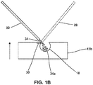
- Figure 1B is a conceptual and schematic block diagram illustrating accumulation of undeposited material 34a in a component 12b having a build direction along an upward direction defined with respect to gravity (see arrow). If solid material 34 is deposited in a downward direction (for example, in a direction directly or inclined toward gravitational forces), undeposited material 34a may accumulate on a surface of substrate 13, or eventually be incorporated within a bulk of substrate 13, or may accumulate within chamber 18, for example, as shown in Figure 1B .
- inverted directed energy deposition may be used, for example, as shown in Figure 1A .
- component 13 is above directed energy deposition tool 16, for example, with stream 32 directed upwards against gravitational force towards molten pool 30 on substrate 13, undeposited material 34 may fall away from substrate 13.
- undeposited material 34a may fall in a downward direction defined by gravitational force away from substrate 13, so that undeposited material 34a no longer accumulates at substrate 13.
- substrate 13 may be inverted so that molten pool 30 faces a downward direction defined with respect to gravity.
- Controller 20 may control material source 22 to direct stream 32 of solid material 34 to molten pool 30 in an upward direction defined with respect to gravity.
- Material for example, solid material 34, may combine with molten pool 30, for example, by melting or fusing into molten pool 30, to form a deposited volume of a plurality of deposited volumes.
- the plurality of deposited volumes defines partially fabricated, and eventually, completely fabricated, component 12.
- the plurality of deposited volumes may define a volume or region of component 12.
- the plurality of deposited volumes may define a surface of chamber 18.
- controller 12 may progressively fabricate component 12 in a downward build direction such that substantially no undeposited material 34a accumulates within component 12, for example, within chamber 18, as shown in FIGS. 2A-2C.
- Figure 2A is a conceptual cross-sectional diagram of an example substrate 13b including a partially fabricated component 12b defining a partially-fabricated chamber 18b.
- Example substrate 13b includes molten pool 30 at a surface of partially-fabricated chamber 18b.
- Figure 2B is a conceptual cross-sectional diagram of an example substrate 13c including a component 12c defining a partially-fabricated chamber 18c.
- Example substrate 13c includes molten pool 30 at a surface defining partially-fabricated chamber 18c.
- Figure 2C is a conceptual cross-sectional diagram of an example substrate 13d including a component 12d defining a chamber 18d. Chamber 18d is completely defined and substantially conforms to digital representation 18a. Chamber 18d is substantially free of undeposited material 34a.
- Example substrate 13c includes molten pool 30 at a surface of component 12d, that is in a downward direction relative to chamber 18d.
- build platform 15 may remain stationary as component 12 is fabricated.
- build platform 15 may be movable or rotatable, for example, along one or more axes, and controller 20 may control the position of build platform 15.
- controller 20 may successively move build platform 15 against the build direction, or to change the build location or location of molten pool 30 by changing the orientation of build platform 15, and that of component 12 or substrate 13, relative to stream 32 and energy beam 28.
- controller 20 may control imaging device 26 to image one or more of surfaces, regions, or volumes of component 12, substrate 13, build platform 15, molten pool 30, material 34, undeposited material 34a, or stream 32. Controller 20 may periodically or continuously compare the build images with digital representation 12a to verify that component 12 substantially conforms (e.g., conforms or nearly conforms) to digital representation 12a, during fabrication through completion. In some examples, controller 20 may control one or more of material source 22, energy source 24, and build platform 15 based on the build images and digital representation 12a. For example, controller 20 may be configured to control build platform 15 and material source 22, energy source 24, and/or imaging device 26 to translate and/or rotate along at least one axis to position component 12 relative to stream 32, energy beam 28, and/or imaging device 26.
- Positioning component 12 relative to stream 32, energy beam 28, and/or imaging 26 may include positioning a predetermined surface (e.g., a surface to which material is to be added) of component 12 in a predetermined orientation relative to material source 22, energy source 24, and/or imaging device 26, so that material is added in regions or volumes based on digital representation 12a.
- a predetermined surface e.g., a surface to which material is to be added
- system 10 may fabricate component 12 based on digital representation 12a using directed energy deposition
- system 10 may also fabricate component 12 by a combination of directed energy deposition and subtractive machining of component 12 or substrate 13.
- system 10 may optionally include machining tool 38 for one or more of milling, grinding, drilling, turning, burnishing, polishing, laser cutting, or otherwise machining component 12.
- portions of component 12 may be fabricated by machining tool 38, for example, based on digital representation 12a.
- controller 20 may control machining tool 38 before, during, or after directed energy deposition of one or more portions of component 12.
- controller 20 may control directed energy deposition tool 16 to fabricate a first volume of component 12.
- Controller 20 may compare the first volume of component 12 to the corresponding volume of digital representation 12a, for example, using images received from imaging device 26. In response to determining that portions of component 12 formed by directed energy deposition do not substantially conform to digital representation 12a, controller 20 may then control machining tool 38 to further machine component 12 based on digital representation 12a.
- controller 20 may control machining tool 38 to machine non-conforming portions of component 12 formed by directed energy deposition
- controller 20 may first control machining tool 38 to fabricate a first portion of component 12 using machining, and subsequently control direct energy deposition tool 16 to fabricate a second portion of component 12 on the machined first portion.
- controller 20 may control machining tool 38 to machine a portion of component 12 to define a first chamber surface.
- Controller 20 may then control directed energy deposition tool 16 to subsequently form plurality of deposited volumes on the first chamber surface, to define the ultimate geometry of a chamber surface, for example, a surface of chamber 18.
- controller 20 may use one or both of machining tool 38 and directed energy deposition tool 16 at different stages of fabricating component 12.
- debris, dust, or machined material generated by machining of component 12 or substrate 13 by machining tool 38 may fall away from substrate 13 in a downward direction.
- one or both of machined material and undeposited material 34a may fall away from substrate 13 to prevent the accumulation of one or both of machine material and undeposited material 34a within component 12 or substrate 13.
- controller 20 may control build platform 15 to orient substrate 13 to allow undeposited material 34a from stream 32 to substantially fall away from substrate 13 in a direction defined with respect to gravity (for example, in the direction of the arrow in Figure 1A ).
- controller 20 may control build platform 15 to orient (or reorient) substrate 13 such that substantially all of undeposited material 34a is unencumbered by any portion of substrate 13, and is free to fall away from substrate 13.
- substrate 13 may be orientated such that partly fabricated component 12 defining partial chamber 18 has an opening that faces downward or inclined downwards such that substantially all of undeposited material 34a within partial chamber 18 departs or falls away from chamber 18 towards gravitational forces. Thus, chamber 18 eventually will be substantially free of undeposited material 34a.
- controller 20 may control build platform 15 to move substrate 13 to cause undeposited material 34a from stream 32 to substantially fall away from substrate 13 in a direction defined with respect to gravity.
- controller 20 may control build platform 15 to shake, vibrate, spin, rotate, or otherwise move substrate 13 to propel or otherwise force undeposited material 34a away from substrate 13, for example, in a downward direction.
- controller 20 may control directed energy deposition tool 16 or other components to cause one or more of substrate 13, energy beam 28, and stream 32 to move or reorient relative to one another.
- controller 20 may simultaneously control build platform 15 to cause substrate 13 to move and control one or both of material source 22 and energy source 24 to respectively cause one or both of stream 32 and energy beam 28 to move or reorient relative to the substrate.
- example system 10 described above may be used to fabricate a component using inverted directed energy deposition, such that the component is substantially free of undeposited material.
- the component may define a chamber that is substantially free of undeposited material.
- the chamber may include channels, for example, cooling channels, apertures, for example, cooling holes or impingement apertures, voids for reducing weight, apertures that may be used to join component 12 to another component, for example, by filling with a joining or brazing composition, or other voids or regions free of material.
- the chamber may have a predetermined cross-section, for example, a curved, a polygonal, or a piecewise curved or polygonal cross-section.
- System 10 may be used to fabricate components, for example, using example techniques described with reference to Figure 3 . However, system 10 may be used to implement other suitable example techniques according to the disclosure.
- Figure 3 is a flow diagram illustrating an example technique for directed energy deposition of a component.
- the example technique of Figure 3 may partly or wholly be performed by example system 10 of Figure 1A , and is described in some examples below with reference to example system 10. However, in some examples, one or more steps of the example technique of Figure 3 may be performed by other example systems.
- the example technique of Figure 3 may include controlling, by computing device 14, based on digital representation 12a, directed energy deposition tool 16 to direct energy source 24 to form molten pool 30 and direct material 34 to molten pool 30, to fabricate component 12.
- the example technique of Figure 3 may include, controlling, by computing device 14, based on digital representation 12a of component 12, energy source 24 to direct energy beam 28 at substrate 13 to form molten pool 30 (40).
- molten pool 30 may be formed before stream 32 is directed towards substrate 13.
- computing device 14 may control energy source 24 to direct energy beam 28 at substrate 13 to form a series of molten pools 30, and control material source 22 to direct stream 32 to each of the series of molten pools 30.
- computing device 14 may control energy source 24 to direct energy beam 28 at substrate 13 to form an advancing molten pool, for example, a molten pool having a leading edge that advances along a path, and having a trailing region along the path into which material 34 may be incorporated.
- the example technique of Figure 3 may also include controlling, by computing device 14, material source 22 to direct stream 32 of solid material 34 to molten pool 30 in an upward direction defined with respect to gravity (42).
- Substrate 13 defines a surface having molten pool 30.
- Molten pool 30 may face a downward direction defined with respect to gravity.
- Solid material 34 combines with molten pool 30 to form a deposited volume of a plurality of deposited volumes.
- the plurality of deposited volumes may define component 12.
- the plurality of deposited volumes may define chamber 18.
- Material source 22 may deliver solid material 34 from stream 32 that may accompany, or lag energy beam 28.
- stream 32 may deliver solid material 34 simultaneously with the incidence of energy beam 28 on substrate 13.
- stream 32 may deliver solid material 34 at a region after energy beam 28 has passed the region to form molten pool 30.
- computing device 14 may control energy source 24 to direct energy beam 28 to form molten pool 30 on a surface that defines chamber 18.
- computing device 14 may direct energy beam 28 at a series of locations, forming a series of molten pools 30 along a path that defines a three-dimensional surface of chamber 18.
- chamber 18 may be spherical, and the path may be spiral, logarithmic, arcuate, or any other path that eventually defines a sphere.
- chamber 18 may have any suitable geometry, including cuboid, parallelepiped, spheroid, oblate, ellipsoid, combinations thereof, or any other three dimensional closed or partially closed surface.
- Computing device 14 may direct energy beam 28 at a series of locations based on digital representation 18a of chamber 18, so that the series of molten pools 30 or an advancing molten pool substantially covers the surface defining chamber 18.
- Computing device 14 may direct material 34 from stream 32 so that it is incorporated into series of molten pools 30 or the advancing molten pool to eventually form a plurality of deposited volumes substantially covering and defining chamber 18 as component 12 is built in the downward build direction.
- the example technique of Figure 3 may optionally include, controlling, by computing device 14, imaging device 26 to image one or more of substrate 13, molten pool 30, and stream 32 (46).
- computing device 14 may periodically or continuously compare the build images received from imaging device 26 with digital representation 12a to verify that component 12 substantially conforms (e.g., conforms or nearly conforms) to digital representation 12a, during fabrication through completion.
- controller 20 may control one or more of material source 22, energy source 24, and build platform 15 based on the location or orientation of one or more of material source 22, energy source 24, molten pool 30, build platform 15, determined from images received from imaging device 26.
- computing device 14 may accordingly reposition the component of system 10 that has deviated from specifications, based on the images received from imaging device 26.
- the example technique of Figure 3 may further include, controlling, by computing device 14, material source 22 and energy source 24 to define a build direction of component 12 in the downward direction.
- computing device 14 may control material source 22 and energy source 24 so that a series of molten pools 30 or an advancing molten pool is formed along a path that eventually moves in the downward direction, and so that material 34 is incorporated into molten pool 30 to define layers or portions of component in a downward build direction. Maintaining the downward build direction may prevent accumulation of undeposited material 34a within chamber 18 or otherwise within component 12, for example, by allowing or causing undeposited material 34a to fall away from component 12 in the downward direction.
- the example technique of Figure 3 may further include, controlling, by computing device 14, build platform 15 configured to hold substrate 13, to orient substrate 13 to allow undeposited material 34a from stream 32 to substantially fall away from substrate 13 in a direction defined with respect to gravity (48).
- computing device 14 may additionally or alternatively control build platform 15 to move substrate 13 to cause undeposited material 34a to substantially fall away from substrate 13 in the direction defined with respect to gravity.
- causing or allowing undeposited material 34a away from substrate 13 may cause or allow component 12 to be substantially free of undeposited material 34a.
- chamber 18 may be substantially free of undeposited material 34a from stream 32 of solid material 34.
- systems and techniques described above may be used to fabricate a component that is substantially free of undeposited material, for example, a component defining a chamber that is substantially free of undeposited material, based on a digital representation of the component.
- processors including one or more microprocessors, digital signal processors (DSPs), application specific integrated circuits (ASICs), field programmable gate arrays (FPGAs), or any other equivalent integrated or discrete logic circuitry, as well as any combinations of such components.
- DSPs digital signal processors
- ASICs application specific integrated circuits
- FPGAs field programmable gate arrays
- processors may generally refer to any of the foregoing logic circuitry, alone or in combination with other logic circuitry, or any other equivalent circuitry.
- a control unit including hardware may also perform one or more of the techniques of this disclosure.
- Such hardware, software, and firmware may be implemented within the same device or within separate devices to support the various techniques described in this disclosure.
- any of the described units, modules or components may be implemented together or separately as discrete but interoperable logic devices. Depiction of different features as modules or units is intended to highlight different functional aspects and does not necessarily imply that such modules or units must be realized by separate hardware, firmware, or software components. Rather, functionality associated with one or more modules or units may be performed by separate hardware, firmware, or software components, or integrated within common or separate hardware, firmware, or software components.
- the techniques described in this disclosure may also be embodied or encoded in a computer system-readable medium, such as a computer system-readable storage medium, containing instructions. Instructions embedded or encoded in a computer system-readable medium, including a computer system-readable storage medium, may cause one or more programmable processors, or other processors, to implement one or more of the techniques described herein, such as when instructions included or encoded in the computer system-readable medium are executed by the one or more processors.
- Computer system readable storage media may include random access memory (RAM), read only memory (ROM), programmable read only memory (PROM), erasable programmable read only memory (EPROM), electronically erasable programmable read only memory (EEPROM), flash memory, a hard disk, a compact disc ROM (CD-ROM), a floppy disk, a cassette, magnetic media, optical media, or other computer system readable media.
- RAM random access memory
- ROM read only memory
- PROM programmable read only memory
- EPROM erasable programmable read only memory
- EEPROM electronically erasable programmable read only memory
- flash memory a hard disk, a compact disc ROM (CD-ROM), a floppy disk, a cassette, magnetic media, optical media, or other computer system readable media.
- an article of manufacture may comprise one or more computer system-readable storage media.
Landscapes
- Engineering & Computer Science (AREA)
- Physics & Mathematics (AREA)
- Optics & Photonics (AREA)
- Chemical & Material Sciences (AREA)
- Mechanical Engineering (AREA)
- Manufacturing & Machinery (AREA)
- Materials Engineering (AREA)
- Plasma & Fusion (AREA)
- Automation & Control Theory (AREA)
- General Engineering & Computer Science (AREA)
- Analytical Chemistry (AREA)
- Powder Metallurgy (AREA)
Abstract
Description
- The present disclosure generally relates to technique for forming a component using directed energy deposition.
- Additive manufacturing, for example, directed energy deposition techniques, may be used to fabricate a component having a predetermined three-dimensional structure, typically by depositing material layer-by-layer or volume-by-volume to form the structure, rather than by removing material from an existing component. Additive manufacturing may be advantageous in many situations, such as rapid prototyping, forming components with complex three-dimensional structures, or the like.
- In one aspect, there is provided a method comprising controlling, by a computing device, a material source to direct a stream of solid material to a molten pool in an upward direction defined with respect to gravity, wherein a substrate defines a surface having the molten pool, wherein the molten pool faces a downward direction defined with respect to gravity, wherein the material combines with the molten pool to form a deposited volume of a plurality of deposited volumes, and wherein the plurality of deposited volumes defines a component.
- The method may further comprise controlling, by the computing device, a build platform configured to hold the substrate, to orient the substrate to allow undeposited material from the stream of solid material to substantially fall away from the substrate in a downward direction defined with respect to gravity.
- Optionally, the method may further comprise controlling, by the computing device, the build platform to move the substrate to cause undeposited material from the stream of solid material to substantially fall away from the substrate in the downward direction defined with respect to gravity.
- The method may further comprise controlling, by the computing device, based on a digital representation of the component, an energy source to direct an energy beam at the substrate to form the molten pool.
- The surface may comprise a chamber surface at which the molten pool is formed. The control of the energy source may comprise advancing the molten pool along a path on the surface. The control of the material source may comprise directing the stream of solid material to the advancing molten pool along the path to form the plurality of deposited volumes. The plurality of deposited volumes may define a chamber comprising the chamber surface.
- The chamber may be substantially free of undeposited material from the stream of solid material.
- The method may further comprise controlling, by the computing device, the material source and the energy source to define a build direction of the component in the downward direction.
- The method may further comprise controlling, by the computing device, an imaging device to image one or more of the substrate, the molten pool, and the stream of solid material.
- Computer-readable instructions executable by a computing device may be provided that cause the computer to perform the aforesaid method. The computer-readable instructions may be encoded on a computer-readable medium.
- In another aspect there is provided a system comprising: a material source; a substrate having a molten pool on a surface of the substrate, wherein the molten pool faces a downward direction defined with respect to gravity; and a computing device; wherein the computing device is configured to: control the material source to direct a stream of solid material to the molten pool in an upward direction defined with respect to gravity, wherein the material combines with the molten pool to form a deposited volume of a plurality of deposited volumes, and wherein the plurality of deposited volumes defines a component.
- The system may further comprise a build platform configured to hold the substrate. The computing device may be further configured to control the build platform to orient the substrate to allow undeposited material from the stream of solid material to substantially fall away from the substrate in a direction defined with respect to gravity.
- Optionally, the computing device may be further configured to control the build platform to move the substrate to cause undeposited material from the stream of solid material to substantially fall away from the substrate in the direction defined with respect to gravity.
- The system may further comprise an energy source. The computing device may be configured to control, based on a digital representation of the component, the energy source to direct an energy beam at the substrate to form the molten pool.
- The surface may comprise a chamber surface at which the molten pool is formed. The computing device may be configured to control the energy device to advance the molten pool along a path on the surface. The computing device may be configured to control the material source to direct the stream of solid material to the advancing molten pool along the path to form the plurality of deposited volumes. The plurality of deposited volumes may define a chamber comprising the chamber surface.
- The chamber may be substantially free of undeposited material from the stream of solid material.
- The computing device may be configured to control the material source and the energy source to define a build direction of the component in the downward direction.
- The system may further comprise an imaging device. The computing device may be configured to control the imaging device to image one or more of the substrate, the molten pool, and the stream of solid material.
- The details of one or more examples are set forth in the accompanying drawings and the description below. Other features, objects, and advantages will be apparent from the description and drawings, and from the claims.
- The invention will now be described by way of example only with reference to the accompanying drawings, which are purely schematic and not to scale, and in which:
-
Figure 1A is a conceptual and schematic block diagram illustrating an example system for directed energy deposition of a component; -
Figure 1B is a conceptual and schematic block diagram illustrating accumulation of undeposited material in a component having a build direction along an upward direction defined with respect to gravity; -
Figure 2A is a conceptual cross-sectional diagram of an example substrate including a component defining a partially-fabricated chamber; -
Figure 2B is a conceptual cross-sectional diagram of an example substrate including a component defining a partially-fabricated chamber; -
Figure 2C is a conceptual cross-sectional diagram of an example substrate including a defining a chamber; and -
Figure 3 is a flow diagram illustrating an example technique for directed energy deposition of a component. - The disclosure describes example systems and techniques for directed energy deposition for manufacturing components. Directed energy deposition systems typically deposit successive layers or volumes of material along a build direction based on a digital representation of a component. In some examples, example techniques for directed energy deposition may include directing an energy beam at a region of a component to form an advancing molten pool and delivering material to the advancing molten pool, resulting in combining of the material and a substrate of the component by sintering or melting, to form a deposited volume of a plurality of deposited volumes. The plurality of deposited volumes may define the component, for example, a volume of the component defining a chamber. During the depositing, uncombined, unmelted, or otherwise undeposited material from the stream may accumulate within depressions, chambers, or voids on or within components fabricated by additive manufacturing as successive layers are deposited. If the accumulated material is not removed, the finished article may define chambers that include residual material. Such residual material may be undesirable, for example, because they may change the mass or the mass distribution of the component, may lead to unintended vibration frequencies during operation of the component, may block channels or openings, or may result in an audible sound such as rustling or rattling.
- In accordance with examples of this disclosure, to substantially avoid accumulation of such residual uncombined or otherwise undeposited material, an example system may use inverted directed energy deposition. For example, the example system may include a computing device that controls a material source to direct a stream of solid material to a molten pool in an upward direction defined with respect to gravity. The material may substantially combine with the molten pool to form a deposited volume of a plurality of deposited volumes. The plurality of deposited volumes defines a component. Undeposited material from the stream of solid material may fall away from the substrate in a downward direction defined with respect to gravity, so that the undeposited material does not accumulate within a chamber defined by the plurality of deposited volumes. Thus, in accordance with examples of this disclosure, systems and techniques are provided to fabricate components defining chambers that may be substantially free of undeposited or residual material.
- A downward direction according to the disclosure may include any direction directly towards or inclined towards a gravitational force. For example, a direct downward direction may be parallel to the direction of ambient gravity. An inclined downward direction may point along an inclined axis greater than about 1 degrees, or greater than about 30 degrees, or less than about 60 degrees, or less than about 90 degrees relative to the direction of ambient gravity. An upward direction may include a direction directly away from or against the gravitational force, or inclined away from or against ambient gravity. For example, a direct upward direction may be antiparallel to the direction of ambient gravity. An inclined upward direction may point along an inclined axis greater than about 1 degrees, or greater than about 30 degrees, or less than about 60 degrees, or less than about 90 degrees relative to the direction against ambient gravity. In this way, as used here, downward and upward may be defined with respect to the direction of gravity.
-
Figure 1A is a conceptual and schematic block diagram illustrating anexample system 10 for directed energy deposition of acomponent 12.Example system 10 includes acomputing device 14, a directedenergy deposition tool 16, acontroller 20, amaterial source 22, anenergy source 24, and animaging device 26. -
Component 12 may include any structure which may be fabricated using directed energy deposition. For example,component 12 may include a gas turbine engine component, such as, a turbine blade, a turbine vane, a shroud, a seal fin, a platform, an airfoil, or the like. Similarly,component 12 may include structural features and geometry of any size, shape, or both. In some examples, such as some examples in whichcomponent 12 include a gas turbine engine component,component 12 may include a metal or alloy substrate. For example,component 12 may include one or more of nickel, cobalt, nickel alloys, cobalt alloys, superalloys, or their combinations.Component 12 may include single crystal or polycrystalline materials. For example,component 12 may include magnesium based, nickel based, ferrous, and titanium alloys. An example of a single crystal nickel based alloy is CMSX-4. In some examples, the alloys may include alloying additions including at least one of Mn, Mg, Cr, Si, Co, W, Ta, Al, Ti, Hf, Re, Mo, Ni, Fe, B, Nb, V, C, and Y. In some examples,component 12 may include composite materials. - In some examples,
component 12 defines a depression, aperture, or void (collectively, "chamber"). In some examples, the chamber may include channels, for example, cooling channels; apertures, for example, cooling holes or impingement apertures; voids for reducing weight; apertures that may be used to joincomponent 12 to another component, for example, by filling with a joining or brazing composition or a mechanical fastener; or other voids or regions free of material. -
Computing device 14 may controlsystem 10 for fabricatingcomponent 12.Computing device 14 may include any of a wide range of devices, including computer servers, desktop computers, notebook (i.e., laptop) computers, tablet computers, and the like. In some examples,computing device 14 may include a processor. The processor may include one or more microprocessors, digital signal processors (DSP), application specific integrated circuits (ASIC), field programmable gate arrays (FPGA), or other digital logic circuitry.Computing device 14 may be communicatively coupled to directedenergy deposition tool 16 and configured to control directedenergy deposition tool 16. - In some examples,
computing device 14 may generate or store adigital representation 12a ofcomponent 12. In examples in whichcomponent 12 includeschamber 18,digital representation 12a may include a digital representation ofchamber 18a generally corresponding tochamber 18 ofcomponent 12. In some examples,computing device 14 may control directedenergy deposition tool 16 to fabricatecomponent 12 based ondigital representation 12a. - In some examples, directed
energy deposition tool 16 may include acontroller 20 for controlling one or more ofmaterial source 22,energy source 24, andimaging device 26.Computing device 14 may send control signals tocontroller 20 for controlling directenergy deposition tool 16. For example,computing device 14 may send operational signals to and receive status signals fromcontroller 20 to control and monitor the operation of directedenergy deposition tool 16. In some examples,computing device 14 may not control directedenergy deposition tool 16, andcontroller 20 may be configured to receive signals indicative ofdigital representation 12a from computingdevice 14 and to control directedenergy deposition tool 16 based ondigital representation 12a to fabricatecomponent 12. Alternatively,additive manufacturing tool 16 may not includecontroller 20, and, instead ofcontroller 20,computing device 14 may control one or more ofmaterial source 22,energy source 24,imaging device 26, and buildplatform 15 according to examples described with reference tocontroller 20. - In some examples,
system 10 may include abuild platform 15 to holdcomponent 12.Build platform 15 may include one or more of an adhesive layer, an adhesive surface or pad, a coating, build tape, platform tape, kapton tape, blue tape, hooks, straps, brackets, or other fasteners to holdcomponent 12 substantially stationary relative to buildplatform 15. In some examples,component 12 may be bonded to buildplatform 15 by a thin layer of fused or molten material adhering to a surface ofbuild platform 15. In some examples, buildplatform 15 continues to hold partially or completely fabricatedcomponent 12 in various configurations, including upwards, downwards, sideways, or any other orientation with respect to gravity, untilcomponent 12 is detached, for example, by physical, mechanical, or chemical separation frombuild platform 15. In some examples,system 10 may not includebuild platform 15, andcontroller 20 may control the position and orientation ofcomponent 12, for example, by controlling an industrial robot, a movable platform, or a multi-axisstage supporting component 12. - In some examples, one or both of at least partially fabricated
component 12 and part or whole ofbuild platform 15 may be considered to form asubstrate 13. In some examples, directedenergy deposition tool 16 may deposit material onsubstrate 13 to eventually fabricatecomponent 12, for example, held onbuild platform 15. In some examples,substrate 13 may include a base component on whichcomponent 12 is further formed. The base component may be formed of any material to which material may be added using directed energy deposition or material addition. In some examples,substrate 13 may include a damaged component on whichcomponent 12 is fabricated as part of a repair region, repair volume, or repair structure. - In examples in which
component 12 is fabricated over a base component or a damaged component, the base or damaged component may be fabricated using any suitable technique for manufacturing metal or alloy components. For example, the base or damaged component may be fabricated using at least one of casting, molding, stamping, cutting, punching, milling, etching, welding, or other metal working techniques. In an example, the base or damaged component itself may be fabricated using directed energy deposition. Thus, example systems and techniques described herein may be used to repair damage to various gas turbine engine components, for example, by restoring damaged components so that they conform to predetermined specifications. - In some examples,
controller 20 may control, based ondigital representation 12a,energy source 24 to direct anenergy beam 28 atsubstrate 13, for example, at a surface ofsubstrate 13.Energy source 24 may include a power source such as a laser source or an electron beam source (not shown) and output theenergy beam 28 directed atsubstrate 13. Thus, in some examples,energy beam 28 may include a laser beam, a plasma, light, electromagnetic radiation, an electron beam, or another form of focused energy absorbable by the material ofcomponent 12, the material to be added tocomponent 12, or both, and sufficiently strong to heat the material to sinter or melt. In some examples,energy beam 28 may include both the laser beam and the electron beam. - In some examples,
energy source 24 may include laser sources including a gas, solid-state, semiconductor, dye, or any other laser source that may be used for directed energy deposition. In some examples,energy source 24 may include an electron beam that includes a beam of electrons controlled by electronic and magnetic fields. In some examples, for example, whereenergy beam 28 includes an electron beam,system 10 may at least partially or wholly be under a reduced pressure or a vacuum.Controller 20 may control the position and orientation ofenergy source 24 andenergy beam 28, for example, by controlling an industrial robot or a movable platform supportingenergy source 24, or by controlling an optical path ofenergy beam 28 by controlling optical media such as reflectors, refractors, filters, and the like. -
Controller 20 may control various parameters ofenergy source 24, including the instantaneous power, peak power or intensity, power pulsing, average beam power, a peak beam power density, a beam heat input, travel speed, wavelength, direction, and orientation.Energy beam 28 may be focused or directed by a focusing lens along or on a path. Thus,controller 20 may controlenergy source 24 to advanceenergy beam 28 along a path to formmolten pool 30 onsubstrate 13. -
Energy beam 28 may interact with material ofsubstrate 13, for example, by fusing, melting, sintering, or otherwise modifying the material ofsubstrate 13 at a focal region ofenergy beam 28 to form amolten pool 30 at a surface ofsubstrate 13. In some examples,molten pool 30 is adjacent an existing surface ofcomponent 12. In some examples,molten pool 30 is adjacent an initial surface, for example, a pilot surface or coating applied to buildplatform 15. In some examples,controller 20 may controlenergy source 24 to emit a diffuse energy beam, or a patterned array of beams, for example, a light pattern. The focal region may change ascomponent 12 is fabricated, for example, along regions or surfaces of partly fabricatedcomponent 12, based ondigital representation 12a. In some examples,controller 20 may cause directedenergy deposition tool 16 to fabricatecomponent 12 by forming molten pools at different build locations along a tool path, and depositing material into successive molten pools to form a plurality of deposited volumes. Thus,controller 20 may ultimately deposit material in molten pools along a predetermined build direction, for example downwards (for example, directly toward or inclined toward a gravitational force). - In some examples,
controller 20 may separately controlmaterial source 22 andenergy source 24, for example, by separately controllingenergy source 24 to directenergy beam 28 along a series of build locations to define a series ofmolten pools 30 or advancingmolten pool 30, at successive focal regions or build locations to fabricatecomponent 12 based ondigital representation 12a, and controllingmaterial source 22 to directstream 32 to deposit a layer or volume ofmaterial 34 at or withinmolten pool 30. Therefore,controller 20 may direct a build location or moltenpool 30 along a two-dimensional or three-dimensional tool path to fabricatecomponent 12 based ondigital representation 12a. - In some examples,
controller 20 may controlmaterial source 22 of directedenergy deposition tool 16 to direct astream 32 ofsolid material 34 atmolten pool 30.Controller 20 may control the position and orientation of material source 2 andstream 32, for example, by controlling an industrial robot, a movable platform, or a multi-axis stage that supportsmaterial source 20.Stream 32 may include fluid, powder, wire, particles, suspension, material suspended in a carrier fluid, or any other form of material that is susceptible toenergy beam 28 to be deposited onsubstrate 13. For example,stream 32 may includesolid material 34 in the form of ceramic or metallic powders. In some examples,material stream 32 may includesolid material 34 that includes nickel, iron, or titanium alloys and optionally one or more alloying additions including one or more of Mn, Mg, Cr, Si, Co, W, Ta, Al, Ti, Hf, Re, Mo, Ni, Fe, B, Nb, V, C, and Y. In some examples,stream 32 may includesolid material 34 that includes powders including one or more of polycrystalline nickel base superalloys or cobalt base superalloys, such as an alloy including NiCrAlY or CoNiCrAlY. - In some examples,
solid material 34 delivered bymaterial source 22 may include a composition substantially the same as (e.g., the same or nearly the same as) the composition of the material from whichcomponent 12 is formed. In other examples,solid material 34 delivered bymaterial source 22 may include a composition different from the composition of the material from whichcomponent 12 is formed. -
Material source 22 may include one or more delivery ports or delivery nozzles through whichsolid material 34exits material source 22.Controller 20 may controlmaterial source 22 to deliversolid material 34 instream 32 tomolten pool 30. For example,material source 22 may deliver powder in conical shaped stream through a powder delivery annulus ofmaterial source 22 directed towardsmolten pool 30.Controller 20 may control a material flux of thestream 32, or other operating parameters ofstream 32, for example, a carrier gas flow rate. In some examples,material source 22 may include a plurality of nozzles such that a powder stream having a converging profile is delivered bymaterial source 22. For example, each nozzle of the plurality of nozzles may be substantially directed towards a target delivery zone ormolten pool 30. - In some examples,
solid material 34 may be combined or otherwise incorporated intomolten pool 30 to define a deposited volume. For example, after combining withmolten pool 30,solid material 34 andmolten pool 30 may solidify or otherwise change state into a deposited volume of a plurality of deposited volumes. In some examples,controller 20 may controlenergy source 24 andmaterial source 22 to depositsolid material 34 in a series ofmolten pools 34, based ondigital representation 12a, to eventually deposit a plurality of deposited volumes that defines partly fabricated, and eventually, completely fabricated,component 12. - In some examples,
controller 20 may control one or both ofenergy source 24 andmaterial source 22 to define a build direction forcomponent 12, for example, a build direction along the downward direction with respect to gravity, as shown inFigure 1A . The build direction may be a direction in which layers of deposited volumes are deposited by directedenergy deposition tool 16 during the fabrication ofcomponent 12. - While substantially all
solid material 34 fromstream 32 may be combined intomolten pool 30, some ofsolid material 34 may not combine withmolten pool 30. For example, there may be slight misalignment between the path ofenergy beam 28 andstream 32, or local thermal variations or static electricity or other phenomena may deflect some material fromstream 32 away frommolten pool 30. Suchundeposited material 34a may persist as residual material, for example, powder, dust, particles, agglomerates, or partly fused material, in a vicinity ofmolten pool 30, or otherwise onsubstrate 13. The presence ofundeposited material 34a may be undesirable. For example,undeposited material 34a may block or otherwise prevent uniform creation of subsequentmolten pools 30, leading to discontinuities or unacceptable disruptions in the structure ofcomponent 12. In some examples,component 12 may includechamber 18, andundeposited material 34a may accumulate withinchamber 18.Figure 1B is a conceptual and schematic block diagram illustrating accumulation ofundeposited material 34a in acomponent 12b having a build direction along an upward direction defined with respect to gravity (see arrow). Ifsolid material 34 is deposited in a downward direction (for example, in a direction directly or inclined toward gravitational forces),undeposited material 34a may accumulate on a surface ofsubstrate 13, or eventually be incorporated within a bulk ofsubstrate 13, or may accumulate withinchamber 18, for example, as shown inFigure 1B . - To avoid such accumulation of
undeposited material 34a adjacent tomolten pool 30, or on or within a surface, bulk, orchamber 18 ofcomponent 12, inverted directed energy deposition may be used, for example, as shown inFigure 1A . In some examples, ifcomponent 13 is above directedenergy deposition tool 16, for example, withstream 32 directed upwards against gravitational force towardsmolten pool 30 onsubstrate 13,undeposited material 34 may fall away fromsubstrate 13. For example,undeposited material 34a may fall in a downward direction defined by gravitational force away fromsubstrate 13, so thatundeposited material 34a no longer accumulates atsubstrate 13. - In some examples,
substrate 13 may be inverted so thatmolten pool 30 faces a downward direction defined with respect to gravity.Controller 20 may controlmaterial source 22 to directstream 32 ofsolid material 34 tomolten pool 30 in an upward direction defined with respect to gravity. Material, for example,solid material 34, may combine withmolten pool 30, for example, by melting or fusing intomolten pool 30, to form a deposited volume of a plurality of deposited volumes. The plurality of deposited volumes defines partially fabricated, and eventually, completely fabricated,component 12. For example, the plurality of deposited volumes may define a volume or region ofcomponent 12. In some examples, the plurality of deposited volumes may define a surface ofchamber 18. - Thus, in some examples,
controller 12 may progressively fabricatecomponent 12 in a downward build direction such that substantially noundeposited material 34a accumulates withincomponent 12, for example, withinchamber 18, as shown inFIGS. 2A-2C. Figure 2A is a conceptual cross-sectional diagram of anexample substrate 13b including a partially fabricatedcomponent 12b defining a partially-fabricatedchamber 18b.Example substrate 13b includesmolten pool 30 at a surface of partially-fabricatedchamber 18b.Figure 2B is a conceptual cross-sectional diagram of anexample substrate 13c including acomponent 12c defining a partially-fabricatedchamber 18c.Example substrate 13c includesmolten pool 30 at a surface defining partially-fabricatedchamber 18c.Figure 2C is a conceptual cross-sectional diagram of anexample substrate 13d including acomponent 12d defining achamber 18d.Chamber 18d is completely defined and substantially conforms todigital representation 18a.Chamber 18d is substantially free ofundeposited material 34a.Example substrate 13c includesmolten pool 30 at a surface ofcomponent 12d, that is in a downward direction relative tochamber 18d. - In some examples, build
platform 15 may remain stationary ascomponent 12 is fabricated. In other examples, buildplatform 15 may be movable or rotatable, for example, along one or more axes, andcontroller 20 may control the position ofbuild platform 15. In some examples,controller 20 may successively movebuild platform 15 against the build direction, or to change the build location or location of moltenpool 30 by changing the orientation ofbuild platform 15, and that ofcomponent 12 orsubstrate 13, relative to stream 32 andenergy beam 28. - In some examples,
controller 20 may controlimaging device 26 to image one or more of surfaces, regions, or volumes ofcomponent 12,substrate 13,build platform 15,molten pool 30,material 34,undeposited material 34a, orstream 32.Controller 20 may periodically or continuously compare the build images withdigital representation 12a to verify thatcomponent 12 substantially conforms (e.g., conforms or nearly conforms) todigital representation 12a, during fabrication through completion. In some examples,controller 20 may control one or more ofmaterial source 22,energy source 24, and buildplatform 15 based on the build images anddigital representation 12a. For example,controller 20 may be configured to controlbuild platform 15 andmaterial source 22,energy source 24, and/orimaging device 26 to translate and/or rotate along at least one axis to positioncomponent 12 relative to stream 32,energy beam 28, and/orimaging device 26.Positioning component 12 relative to stream 32,energy beam 28, and/orimaging 26 may include positioning a predetermined surface (e.g., a surface to which material is to be added) ofcomponent 12 in a predetermined orientation relative tomaterial source 22,energy source 24, and/orimaging device 26, so that material is added in regions or volumes based ondigital representation 12a. - While
system 10 may fabricatecomponent 12 based ondigital representation 12a using directed energy deposition, in some examples,system 10 may also fabricatecomponent 12 by a combination of directed energy deposition and subtractive machining ofcomponent 12 orsubstrate 13. For example,system 10 may optionally includemachining tool 38 for one or more of milling, grinding, drilling, turning, burnishing, polishing, laser cutting, or otherwise machiningcomponent 12. In some examples, portions ofcomponent 12 may be fabricated by machiningtool 38, for example, based ondigital representation 12a. In some examples,controller 20 may controlmachining tool 38 before, during, or after directed energy deposition of one or more portions ofcomponent 12. For example,controller 20 may control directedenergy deposition tool 16 to fabricate a first volume ofcomponent 12.Controller 20 may compare the first volume ofcomponent 12 to the corresponding volume ofdigital representation 12a, for example, using images received fromimaging device 26. In response to determining that portions ofcomponent 12 formed by directed energy deposition do not substantially conform todigital representation 12a,controller 20 may then controlmachining tool 38 tofurther machine component 12 based ondigital representation 12a. - While in some examples,
controller 20 may controlmachining tool 38 to machine non-conforming portions ofcomponent 12 formed by directed energy deposition, in some examples,controller 20 may first controlmachining tool 38 to fabricate a first portion ofcomponent 12 using machining, and subsequently control directenergy deposition tool 16 to fabricate a second portion ofcomponent 12 on the machined first portion. For example,controller 20 may controlmachining tool 38 to machine a portion ofcomponent 12 to define a first chamber surface.Controller 20 may then control directedenergy deposition tool 16 to subsequently form plurality of deposited volumes on the first chamber surface, to define the ultimate geometry of a chamber surface, for example, a surface ofchamber 18. In some examples,controller 20 may use one or both ofmachining tool 38 and directedenergy deposition tool 16 at different stages of fabricatingcomponent 12. In some examples, debris, dust, or machined material generated by machining ofcomponent 12 orsubstrate 13 by machiningtool 38 may fall away fromsubstrate 13 in a downward direction. Thus, one or both of machined material andundeposited material 34a may fall away fromsubstrate 13 to prevent the accumulation of one or both of machine material andundeposited material 34a withincomponent 12 orsubstrate 13. - In some examples,
controller 20 may controlbuild platform 15 to orientsubstrate 13 to allowundeposited material 34a fromstream 32 to substantially fall away fromsubstrate 13 in a direction defined with respect to gravity (for example, in the direction of the arrow inFigure 1A ). In some examples, after formingmolten pool 30, and after depositing an amount ofmaterial 34 fromstream 32,controller 20 may controlbuild platform 15 to orient (or reorient)substrate 13 such that substantially all ofundeposited material 34a is unencumbered by any portion ofsubstrate 13, and is free to fall away fromsubstrate 13. For example,substrate 13 may be orientated such that partly fabricatedcomponent 12 definingpartial chamber 18 has an opening that faces downward or inclined downwards such that substantially all ofundeposited material 34a withinpartial chamber 18 departs or falls away fromchamber 18 towards gravitational forces. Thus,chamber 18 eventually will be substantially free ofundeposited material 34a. - In some examples,
controller 20 may controlbuild platform 15 to movesubstrate 13 to causeundeposited material 34a fromstream 32 to substantially fall away fromsubstrate 13 in a direction defined with respect to gravity. For example,controller 20 may controlbuild platform 15 to shake, vibrate, spin, rotate, or otherwise movesubstrate 13 to propel or otherwise forceundeposited material 34a away fromsubstrate 13, for example, in a downward direction. - In some examples,
controller 20 may control directedenergy deposition tool 16 or other components to cause one or more ofsubstrate 13,energy beam 28, andstream 32 to move or reorient relative to one another. For example,controller 20 may simultaneously controlbuild platform 15 to causesubstrate 13 to move and control one or both ofmaterial source 22 andenergy source 24 to respectively cause one or both ofstream 32 andenergy beam 28 to move or reorient relative to the substrate. - Thus,
example system 10 described above may be used to fabricate a component using inverted directed energy deposition, such that the component is substantially free of undeposited material. For example, the component may define a chamber that is substantially free of undeposited material. For example, the chamber may include channels, for example, cooling channels, apertures, for example, cooling holes or impingement apertures, voids for reducing weight, apertures that may be used to joincomponent 12 to another component, for example, by filling with a joining or brazing composition, or other voids or regions free of material. The chamber may have a predetermined cross-section, for example, a curved, a polygonal, or a piecewise curved or polygonal cross-section.System 10 may be used to fabricate components, for example, using example techniques described with reference toFigure 3 . However,system 10 may be used to implement other suitable example techniques according to the disclosure. -
Figure 3 is a flow diagram illustrating an example technique for directed energy deposition of a component. The example technique ofFigure 3 may partly or wholly be performed byexample system 10 ofFigure 1A , and is described in some examples below with reference toexample system 10. However, in some examples, one or more steps of the example technique ofFigure 3 may be performed by other example systems. - The example technique of
Figure 3 may include controlling, by computingdevice 14, based ondigital representation 12a, directedenergy deposition tool 16 to directenergy source 24 to formmolten pool 30 anddirect material 34 tomolten pool 30, to fabricatecomponent 12. - The example technique of
Figure 3 may include, controlling, by computingdevice 14, based ondigital representation 12a ofcomponent 12,energy source 24 to directenergy beam 28 atsubstrate 13 to form molten pool 30 (40). For example,molten pool 30 may be formed beforestream 32 is directed towardssubstrate 13. In some examples,computing device 14 may controlenergy source 24 to directenergy beam 28 atsubstrate 13 to form a series ofmolten pools 30, andcontrol material source 22 to directstream 32 to each of the series ofmolten pools 30. In some examples,computing device 14 may controlenergy source 24 to directenergy beam 28 atsubstrate 13 to form an advancing molten pool, for example, a molten pool having a leading edge that advances along a path, and having a trailing region along the path into whichmaterial 34 may be incorporated. - The example technique of
Figure 3 may also include controlling, by computingdevice 14,material source 22 to directstream 32 ofsolid material 34 tomolten pool 30 in an upward direction defined with respect to gravity (42).Substrate 13 defines a surface having moltenpool 30.Molten pool 30 may face a downward direction defined with respect to gravity.Solid material 34 combines withmolten pool 30 to form a deposited volume of a plurality of deposited volumes. The plurality of deposited volumes may definecomponent 12. In some examples, the plurality of deposited volumes may definechamber 18. -
Material source 22 may deliversolid material 34 fromstream 32 that may accompany, or lagenergy beam 28. In some examples,stream 32 may deliversolid material 34 simultaneously with the incidence ofenergy beam 28 onsubstrate 13. In some examples,stream 32 may deliversolid material 34 at a region afterenergy beam 28 has passed the region to formmolten pool 30. - In some examples,
computing device 14 may controlenergy source 24 to directenergy beam 28 to formmolten pool 30 on a surface that defineschamber 18. For example, andcomputing device 14 may directenergy beam 28 at a series of locations, forming a series ofmolten pools 30 along a path that defines a three-dimensional surface ofchamber 18. For example,chamber 18 may be spherical, and the path may be spiral, logarithmic, arcuate, or any other path that eventually defines a sphere. - While a
spherical chamber 18 is described in some examples,chamber 18 may have any suitable geometry, including cuboid, parallelepiped, spheroid, oblate, ellipsoid, combinations thereof, or any other three dimensional closed or partially closed surface.Computing device 14 may directenergy beam 28 at a series of locations based ondigital representation 18a ofchamber 18, so that the series ofmolten pools 30 or an advancing molten pool substantially covers thesurface defining chamber 18.Computing device 14 may direct material 34 fromstream 32 so that it is incorporated into series ofmolten pools 30 or the advancing molten pool to eventually form a plurality of deposited volumes substantially covering and definingchamber 18 ascomponent 12 is built in the downward build direction. - In some examples, the example technique of
Figure 3 may optionally include, controlling, by computingdevice 14,imaging device 26 to image one or more ofsubstrate 13,molten pool 30, and stream 32 (46). For example,computing device 14 may periodically or continuously compare the build images received fromimaging device 26 withdigital representation 12a to verify thatcomponent 12 substantially conforms (e.g., conforms or nearly conforms) todigital representation 12a, during fabrication through completion. In some examples,controller 20 may control one or more ofmaterial source 22,energy source 24, and buildplatform 15 based on the location or orientation of one or more ofmaterial source 22,energy source 24,molten pool 30,build platform 15, determined from images received fromimaging device 26. For example, if the location or orientation of one or more ofmaterial source 22,energy source 24,stream 32,energy beam 28, ormolten pool 30 deviate from a predetermined configuration required to substantially conformcomponent 12 withdigital representation 12a,computing device 14 may accordingly reposition the component ofsystem 10 that has deviated from specifications, based on the images received fromimaging device 26. - In some examples, the example technique of
Figure 3 may further include, controlling, by computingdevice 14,material source 22 andenergy source 24 to define a build direction ofcomponent 12 in the downward direction. For example,computing device 14 may controlmaterial source 22 andenergy source 24 so that a series ofmolten pools 30 or an advancing molten pool is formed along a path that eventually moves in the downward direction, and so thatmaterial 34 is incorporated intomolten pool 30 to define layers or portions of component in a downward build direction. Maintaining the downward build direction may prevent accumulation ofundeposited material 34a withinchamber 18 or otherwise withincomponent 12, for example, by allowing or causingundeposited material 34a to fall away fromcomponent 12 in the downward direction. - In some examples, the example technique of
Figure 3 may further include, controlling, by computingdevice 14,build platform 15 configured to holdsubstrate 13, to orientsubstrate 13 to allowundeposited material 34a fromstream 32 to substantially fall away fromsubstrate 13 in a direction defined with respect to gravity (48). In some examples,computing device 14 may additionally or alternatively controlbuild platform 15 to movesubstrate 13 to causeundeposited material 34a to substantially fall away fromsubstrate 13 in the direction defined with respect to gravity. In some examples, causing or allowingundeposited material 34a away fromsubstrate 13 may cause or allowcomponent 12 to be substantially free ofundeposited material 34a. For example,chamber 18 may be substantially free ofundeposited material 34a fromstream 32 ofsolid material 34. - Thus, systems and techniques described above may be used to fabricate a component that is substantially free of undeposited material, for example, a component defining a chamber that is substantially free of undeposited material, based on a digital representation of the component.
- The techniques described in this disclosure may be implemented, at least in part, in hardware, software, firmware, or any combination thereof. For example, various aspects of the described techniques may be implemented within one or more processors, including one or more microprocessors, digital signal processors (DSPs), application specific integrated circuits (ASICs), field programmable gate arrays (FPGAs), or any other equivalent integrated or discrete logic circuitry, as well as any combinations of such components. The term "processor" or "processing circuitry" may generally refer to any of the foregoing logic circuitry, alone or in combination with other logic circuitry, or any other equivalent circuitry. A control unit including hardware may also perform one or more of the techniques of this disclosure.
- Such hardware, software, and firmware may be implemented within the same device or within separate devices to support the various techniques described in this disclosure. In addition, any of the described units, modules or components may be implemented together or separately as discrete but interoperable logic devices. Depiction of different features as modules or units is intended to highlight different functional aspects and does not necessarily imply that such modules or units must be realized by separate hardware, firmware, or software components. Rather, functionality associated with one or more modules or units may be performed by separate hardware, firmware, or software components, or integrated within common or separate hardware, firmware, or software components.
- The techniques described in this disclosure may also be embodied or encoded in a computer system-readable medium, such as a computer system-readable storage medium, containing instructions. Instructions embedded or encoded in a computer system-readable medium, including a computer system-readable storage medium, may cause one or more programmable processors, or other processors, to implement one or more of the techniques described herein, such as when instructions included or encoded in the computer system-readable medium are executed by the one or more processors. Computer system readable storage media may include random access memory (RAM), read only memory (ROM), programmable read only memory (PROM), erasable programmable read only memory (EPROM), electronically erasable programmable read only memory (EEPROM), flash memory, a hard disk, a compact disc ROM (CD-ROM), a floppy disk, a cassette, magnetic media, optical media, or other computer system readable media. In some examples, an article of manufacture may comprise one or more computer system-readable storage media.
- Various examples have been described, each of which feature various combinations of features. It will be appreciated by those skilled in the art that, except where clearly mutually exclusive, any of the features may be employed separately or in combination with any other features and the invention extends to and includes all combinations and subcombinations of one or more features described herein.
Claims (15)
- A method comprising:controlling, by a computing device (14), a material source (22) to direct a stream (32) of solid material (34) to a molten pool (30) in an upward direction defined with respect to gravity,wherein a substrate (13) defines a surface having the molten pool,wherein the molten pool faces a downward direction defined with respect to gravity,wherein the solid material combines with the molten pool to form a deposited volume of a plurality of deposited volumes, andwherein the plurality of deposited volumes defines a component (12).
- The method of claim 1, further comprising:controlling, by the computing device, a build platform (15) configured to hold the substrate (13), to orient the substrate to allow undeposited material (34a) from the stream (32) of solid material (34) to substantially fall away from the substrate in a downward direction defined with respect to gravity;and, optionally, controlling, by the computing device, the build platform to move the substrate to cause undeposited material from the stream of solid material to substantially fall away from the substrate in the downward direction defined with respect to gravity.
- The method of claim 1 or claim 2, further comprising:controlling, by the computing device, based on a digital representation (18a) of the component, an energy source (24) to direct an energy beam (28) at the substrate to form the molten pool.
- The method of claim 3,
wherein the surface comprises a chamber surface at which the molten pool is formed,
wherein controlling the energy source comprises advancing the molten pool along a path on the surface,
wherein controlling the material source comprises directing the stream of solid material to the advancing molten pool along the path to form the plurality of deposited volumes,
wherein the plurality of deposited volumes defines a chamber comprising the chamber surface. - The method of claim 4, wherein the chamber (18) is substantially free of undeposited material from the stream of solid material.
- The method of any one of claims 3 to 5, further comprising:controlling, by the computing device, the material source and the energy source to define a build direction of the component in the downward direction.
- The method of any one of claims 1 to 6 further comprising:controlling, by the computing device, an imaging device (26) to image one or more of the substrate, the molten pool, and the stream of solid material.
- A system (10) comprising:a material source (22);a substrate (13) having a molten pool (30) on a surface of the substrate, wherein the molten pool faces a downward direction defined with respect to gravity; anda computing device (14);wherein the computing device is configured to control the material source to direct a stream (32) of solid material (34) to the molten pool in an upward direction defined with respect to gravity,wherein the solid material combines with the molten pool to form a deposited volume of a plurality of deposited volumes, andwherein the plurality of deposited volumes defines a component (12).
- The system of claim 8, further comprising a build platform (15) configured to hold the substrate 913), wherein the computing device is further configured to control the build platform to orient the substrate to allow undeposited material (34a) from the stream (32) of solid material (34) to substantially fall away from the substrate in a direction defined with respect to gravity; and
optionally the computing device is further configured to control the build platform to move the substrate to cause undeposited material from the stream of solid material to substantially fall away from the substrate in the direction defined with respect to gravity. - The system of claim 8 or claim 9, further comprising an energy source (24);
wherein the computing device is configured to control, based on a digital representation of the component, the energy source to direct an energy beam (28) at the substrate to form the molten pool. - The system of claim 10,
wherein the surface comprises a chamber surface at which the molten pool is formed, wherein the computing device is configured to control the energy device to advance the molten pool along a path on the surface,
wherein the computing device is configured to control the material source to direct the stream of solid material to the advancing molten pool along the path to form the plurality of deposited volumes,
wherein the plurality of deposited volumes defines a chamber comprising the chamber surface. - The system of claim 11, wherein the chamber (18) is substantially free of undeposited material from the stream of solid material.
- The system of any one of claims 10 to 12, wherein the computing device is further configured to control the material source and the energy source to define a build direction of the component in the downward direction.
- The system of any one of claims 8 to 13, further comprising an imaging device, wherein the computing device is further configured to control the imaging device (26) to image one or more of the substrate, the molten pool, and the stream of solid material.
- A computer-readable medium encoded with instructions executable by a computing device, that, when executed, cause the computing device to perform the method of any one of claims 1 to 7.
Applications Claiming Priority (1)
| Application Number | Priority Date | Filing Date | Title |
|---|---|---|---|
| US201662398253P | 2016-09-22 | 2016-09-22 |
Publications (1)
| Publication Number | Publication Date |
|---|---|
| EP3300828A1 true EP3300828A1 (en) | 2018-04-04 |
Family
ID=59738153
Family Applications (1)
| Application Number | Title | Priority Date | Filing Date |
|---|---|---|---|
| EP17187191.6A Pending EP3300828A1 (en) | 2016-09-22 | 2017-08-22 | Inverted directed energy deposition |
Country Status (2)
| Country | Link |
|---|---|
| US (1) | US11351634B2 (en) |
| EP (1) | EP3300828A1 (en) |
Cited By (1)
| Publication number | Priority date | Publication date | Assignee | Title |
|---|---|---|---|---|
| US11612986B2 (en) | 2019-12-17 | 2023-03-28 | Rolls-Royce Corporation | Abrasive coating including metal matrix and ceramic particles |
Families Citing this family (4)
| Publication number | Priority date | Publication date | Assignee | Title |
|---|---|---|---|---|
| US11426818B2 (en) | 2018-08-10 | 2022-08-30 | The Research Foundation for the State University | Additive manufacturing processes and additively manufactured products |
| US20230141016A1 (en) * | 2020-03-18 | 2023-05-11 | Alejandro Martinez | System and method of directed energy deposition using a sound field |
| CN115415553B (en) * | 2022-09-16 | 2024-10-15 | 北京科技大学 | Three-dimensional multi-material gradient powder layer laying device and method |
| EP4609971A1 (en) * | 2024-03-01 | 2025-09-03 | GE Avio S.r.l. | Directed energy deposition system and methods for component repairs |
Citations (3)
| Publication number | Priority date | Publication date | Assignee | Title |
|---|---|---|---|---|
| US6180049B1 (en) * | 1999-06-28 | 2001-01-30 | Nanotek Instruments, Inc. | Layer manufacturing using focused chemical vapor deposition |
| US6401001B1 (en) * | 1999-07-22 | 2002-06-04 | Nanotek Instruments, Inc. | Layer manufacturing using deposition of fused droplets |
| EP3045254A1 (en) * | 2015-01-06 | 2016-07-20 | Rolls-Royce Corporation | Method and directed energy deposition material addition system using neuro-fuzzy logic for controlling material addition processes |
Family Cites Families (3)
| Publication number | Priority date | Publication date | Assignee | Title |
|---|---|---|---|---|
| US5837960A (en) | 1995-08-14 | 1998-11-17 | The Regents Of The University Of California | Laser production of articles from powders |
| US6995334B1 (en) * | 2003-08-25 | 2006-02-07 | Southern Methodist University | System and method for controlling the size of the molten pool in laser-based additive manufacturing |
| US8859054B2 (en) | 2010-12-28 | 2014-10-14 | Rolls-Royce Corporation | System and method for depositing material in a substrate |
-
2017
- 2017-08-22 EP EP17187191.6A patent/EP3300828A1/en active Pending
- 2017-09-20 US US15/710,424 patent/US11351634B2/en active Active
Patent Citations (3)
| Publication number | Priority date | Publication date | Assignee | Title |
|---|---|---|---|---|
| US6180049B1 (en) * | 1999-06-28 | 2001-01-30 | Nanotek Instruments, Inc. | Layer manufacturing using focused chemical vapor deposition |
| US6401001B1 (en) * | 1999-07-22 | 2002-06-04 | Nanotek Instruments, Inc. | Layer manufacturing using deposition of fused droplets |
| EP3045254A1 (en) * | 2015-01-06 | 2016-07-20 | Rolls-Royce Corporation | Method and directed energy deposition material addition system using neuro-fuzzy logic for controlling material addition processes |
Cited By (2)
| Publication number | Priority date | Publication date | Assignee | Title |
|---|---|---|---|---|
| US11612986B2 (en) | 2019-12-17 | 2023-03-28 | Rolls-Royce Corporation | Abrasive coating including metal matrix and ceramic particles |
| US12226878B2 (en) | 2019-12-17 | 2025-02-18 | Rolls-Royce Corporation | Abrasive coating including metal matrix and ceramic particles |
Also Published As
| Publication number | Publication date |
|---|---|
| US20180079034A1 (en) | 2018-03-22 |
| US11351634B2 (en) | 2022-06-07 |
Similar Documents
| Publication | Publication Date | Title |
|---|---|---|
| US11351634B2 (en) | Inverted directed energy deposition | |
| EP3213854B1 (en) | Method, system and computer readable storage medium for energy deposition for processing gas turbine engine components | |
| EP3383573B1 (en) | Electron beam additive manufacturing | |
| JP6728389B2 (en) | Sputtering target assembly having a graded intermediate layer and method of making | |
| US6504127B1 (en) | Laser consolidation methodology and apparatus for manufacturing precise structures | |
| Pinkerton | Laser direct metal deposition: theory and applications in manufacturing and maintenance | |
| Merz et al. | Shape deposition manufacturing | |
| US11155502B2 (en) | Method to additively manufacture a fiber-reinforced ceramic matrix composite | |
| JP5797887B2 (en) | Method and apparatus for welding parts made of heat resistant superalloy | |
| US11199202B2 (en) | Acoustic attenuator for a turbomachine and methodology for additively manufacturing said acoustic attenuator | |
| US20160319690A1 (en) | Additive manufacturing methods for turbine shroud seal structures | |
| US20200114425A1 (en) | Suction device for additive production | |
| CN105562688A (en) | Manufacture of a component through selective laser melting | |
| US20180323047A1 (en) | Sputter target backing plate assemblies with cooling structures | |
| Sears | Direct laser powder deposition-'State of the Art' | |
| JP6888874B2 (en) | Addition manufacturing using mobile scanning area | |
| EP3646967B1 (en) | Enhanced cooling during additive manufacturing | |
| US20100018953A1 (en) | Reusable mandrel for solid free form fabrication process | |
| KR20160036583A (en) | Method for creating a textured bond coat surface | |
| CN116917129A (en) | Rotary additive manufacturing systems and methods | |
| Peyre et al. | Additive manufacturing of metal alloys 1: processes, raw materials and numerical simulation | |
| Fearon et al. | Optimisation of layer height control in direct laser deposition | |
| JP7207020B2 (en) | Method for manufacturing metal article having three-dimensional structure | |
| Jhavar et al. | Development of micro-plasma wire deposition process for layered manufacturing | |
| US20160245519A1 (en) | Panel with cooling holes and methods for fabricating same |
Legal Events
| Date | Code | Title | Description |
|---|---|---|---|
| PUAI | Public reference made under article 153(3) epc to a published international application that has entered the european phase |
Free format text: ORIGINAL CODE: 0009012 |
|
| STAA | Information on the status of an ep patent application or granted ep patent |
Free format text: STATUS: THE APPLICATION HAS BEEN PUBLISHED |
|
| AK | Designated contracting states |
Kind code of ref document: A1 Designated state(s): AL AT BE BG CH CY CZ DE DK EE ES FI FR GB GR HR HU IE IS IT LI LT LU LV MC MK MT NL NO PL PT RO RS SE SI SK SM TR |
|
| AX | Request for extension of the european patent |
Extension state: BA ME |
|
| STAA | Information on the status of an ep patent application or granted ep patent |
Free format text: STATUS: REQUEST FOR EXAMINATION WAS MADE |
|
| 17P | Request for examination filed |
Effective date: 20181003 |
|
| RBV | Designated contracting states (corrected) |
Designated state(s): AL AT BE BG CH CY CZ DE DK EE ES FI FR GB GR HR HU IE IS IT LI LT LU LV MC MK MT NL NO PL PT RO RS SE SI SK SM TR |
|
| STAA | Information on the status of an ep patent application or granted ep patent |
Free format text: STATUS: EXAMINATION IS IN PROGRESS |
|
| 17Q | First examination report despatched |
Effective date: 20210421 |
|
| GRAP | Despatch of communication of intention to grant a patent |
Free format text: ORIGINAL CODE: EPIDOSNIGR1 |
|
| STAA | Information on the status of an ep patent application or granted ep patent |
Free format text: STATUS: GRANT OF PATENT IS INTENDED |