EP3300770A1 - Portal imaging during radiotherapy - Google Patents
Portal imaging during radiotherapy Download PDFInfo
- Publication number
- EP3300770A1 EP3300770A1 EP17197721.8A EP17197721A EP3300770A1 EP 3300770 A1 EP3300770 A1 EP 3300770A1 EP 17197721 A EP17197721 A EP 17197721A EP 3300770 A1 EP3300770 A1 EP 3300770A1
- Authority
- EP
- European Patent Office
- Prior art keywords
- source
- imaging device
- gantry
- epid
- axis
- Prior art date
- Legal status (The legal status is an assumption and is not a legal conclusion. Google has not performed a legal analysis and makes no representation as to the accuracy of the status listed.)
- Granted
Links
- 238000003384 imaging method Methods 0.000 title claims abstract description 35
- 238000001959 radiotherapy Methods 0.000 title claims abstract description 29
- 238000011282 treatment Methods 0.000 claims abstract description 44
- 230000033001 locomotion Effects 0.000 claims abstract description 38
- 230000005855 radiation Effects 0.000 claims abstract description 34
- 230000001225 therapeutic effect Effects 0.000 claims description 9
- 230000004913 activation Effects 0.000 claims description 2
- 238000004458 analytical method Methods 0.000 claims description 2
- 230000006378 damage Effects 0.000 abstract description 6
- 206010028980 Neoplasm Diseases 0.000 description 22
- 238000000034 method Methods 0.000 description 6
- 210000003484 anatomy Anatomy 0.000 description 3
- 238000004980 dosimetry Methods 0.000 description 3
- 238000002595 magnetic resonance imaging Methods 0.000 description 3
- 238000004804 winding Methods 0.000 description 3
- 238000013459 approach Methods 0.000 description 2
- 230000002238 attenuated effect Effects 0.000 description 2
- 238000004364 calculation method Methods 0.000 description 2
- 238000002591 computed tomography Methods 0.000 description 2
- 230000003902 lesion Effects 0.000 description 2
- 230000008569 process Effects 0.000 description 2
- 230000003439 radiotherapeutic effect Effects 0.000 description 2
- 238000002728 volumetric modulated arc therapy Methods 0.000 description 2
- 208000027418 Wounds and injury Diseases 0.000 description 1
- 230000009471 action Effects 0.000 description 1
- 210000000481 breast Anatomy 0.000 description 1
- 230000030833 cell death Effects 0.000 description 1
- 230000033077 cellular process Effects 0.000 description 1
- 230000008859 change Effects 0.000 description 1
- 238000000205 computational method Methods 0.000 description 1
- 238000012937 correction Methods 0.000 description 1
- 238000013461 design Methods 0.000 description 1
- 230000001627 detrimental effect Effects 0.000 description 1
- 230000000694 effects Effects 0.000 description 1
- 230000000977 initiatory effect Effects 0.000 description 1
- 208000014674 injury Diseases 0.000 description 1
- 230000010354 integration Effects 0.000 description 1
- 230000001678 irradiating effect Effects 0.000 description 1
- 210000004072 lung Anatomy 0.000 description 1
- 238000004519 manufacturing process Methods 0.000 description 1
- 230000007246 mechanism Effects 0.000 description 1
- 238000011369 optimal treatment Methods 0.000 description 1
- 210000000056 organ Anatomy 0.000 description 1
- 230000000284 resting effect Effects 0.000 description 1
- 230000035945 sensitivity Effects 0.000 description 1
- 238000013519 translation Methods 0.000 description 1
Images


Classifications
-
- A—HUMAN NECESSITIES
- A61—MEDICAL OR VETERINARY SCIENCE; HYGIENE
- A61N—ELECTROTHERAPY; MAGNETOTHERAPY; RADIATION THERAPY; ULTRASOUND THERAPY
- A61N5/00—Radiation therapy
- A61N5/10—X-ray therapy; Gamma-ray therapy; Particle-irradiation therapy
- A61N5/1048—Monitoring, verifying, controlling systems and methods
- A61N5/1049—Monitoring, verifying, controlling systems and methods for verifying the position of the patient with respect to the radiation beam
-
- A—HUMAN NECESSITIES
- A61—MEDICAL OR VETERINARY SCIENCE; HYGIENE
- A61N—ELECTROTHERAPY; MAGNETOTHERAPY; RADIATION THERAPY; ULTRASOUND THERAPY
- A61N5/00—Radiation therapy
- A61N5/10—X-ray therapy; Gamma-ray therapy; Particle-irradiation therapy
- A61N5/1048—Monitoring, verifying, controlling systems and methods
- A61N5/1071—Monitoring, verifying, controlling systems and methods for verifying the dose delivered by the treatment plan
-
- A—HUMAN NECESSITIES
- A61—MEDICAL OR VETERINARY SCIENCE; HYGIENE
- A61N—ELECTROTHERAPY; MAGNETOTHERAPY; RADIATION THERAPY; ULTRASOUND THERAPY
- A61N5/00—Radiation therapy
- A61N5/10—X-ray therapy; Gamma-ray therapy; Particle-irradiation therapy
- A61N5/103—Treatment planning systems
- A61N5/1036—Leaf sequencing algorithms
-
- A—HUMAN NECESSITIES
- A61—MEDICAL OR VETERINARY SCIENCE; HYGIENE
- A61N—ELECTROTHERAPY; MAGNETOTHERAPY; RADIATION THERAPY; ULTRASOUND THERAPY
- A61N5/00—Radiation therapy
- A61N5/10—X-ray therapy; Gamma-ray therapy; Particle-irradiation therapy
- A61N5/1042—X-ray therapy; Gamma-ray therapy; Particle-irradiation therapy with spatial modulation of the radiation beam within the treatment head
- A61N5/1045—X-ray therapy; Gamma-ray therapy; Particle-irradiation therapy with spatial modulation of the radiation beam within the treatment head using a multi-leaf collimator, e.g. for intensity modulated radiation therapy or IMRT
- A61N5/1047—X-ray therapy; Gamma-ray therapy; Particle-irradiation therapy with spatial modulation of the radiation beam within the treatment head using a multi-leaf collimator, e.g. for intensity modulated radiation therapy or IMRT with movement of the radiation head during application of radiation, e.g. for intensity modulated arc therapy or IMAT
-
- A—HUMAN NECESSITIES
- A61—MEDICAL OR VETERINARY SCIENCE; HYGIENE
- A61N—ELECTROTHERAPY; MAGNETOTHERAPY; RADIATION THERAPY; ULTRASOUND THERAPY
- A61N5/00—Radiation therapy
- A61N5/10—X-ray therapy; Gamma-ray therapy; Particle-irradiation therapy
- A61N5/1048—Monitoring, verifying, controlling systems and methods
- A61N5/1064—Monitoring, verifying, controlling systems and methods for adjusting radiation treatment in response to monitoring
- A61N5/1069—Target adjustment, e.g. moving the patient support
- A61N5/107—Target adjustment, e.g. moving the patient support in real time, i.e. during treatment
-
- A—HUMAN NECESSITIES
- A61—MEDICAL OR VETERINARY SCIENCE; HYGIENE
- A61N—ELECTROTHERAPY; MAGNETOTHERAPY; RADIATION THERAPY; ULTRASOUND THERAPY
- A61N5/00—Radiation therapy
- A61N5/10—X-ray therapy; Gamma-ray therapy; Particle-irradiation therapy
- A61N5/1077—Beam delivery systems
- A61N5/1081—Rotating beam systems with a specific mechanical construction, e.g. gantries
-
- A—HUMAN NECESSITIES
- A61—MEDICAL OR VETERINARY SCIENCE; HYGIENE
- A61N—ELECTROTHERAPY; MAGNETOTHERAPY; RADIATION THERAPY; ULTRASOUND THERAPY
- A61N5/00—Radiation therapy
- A61N5/10—X-ray therapy; Gamma-ray therapy; Particle-irradiation therapy
- A61N5/1077—Beam delivery systems
- A61N5/1083—Robot arm beam systems
-
- A—HUMAN NECESSITIES
- A61—MEDICAL OR VETERINARY SCIENCE; HYGIENE
- A61B—DIAGNOSIS; SURGERY; IDENTIFICATION
- A61B6/00—Apparatus for radiation diagnosis, e.g. combined with radiation therapy equipment
- A61B6/02—Devices for diagnosis sequentially in different planes; Stereoscopic radiation diagnosis
- A61B6/03—Computerised tomographs
- A61B6/032—Transmission computed tomography [CT]
-
- A—HUMAN NECESSITIES
- A61—MEDICAL OR VETERINARY SCIENCE; HYGIENE
- A61N—ELECTROTHERAPY; MAGNETOTHERAPY; RADIATION THERAPY; ULTRASOUND THERAPY
- A61N5/00—Radiation therapy
- A61N5/10—X-ray therapy; Gamma-ray therapy; Particle-irradiation therapy
- A61N5/1048—Monitoring, verifying, controlling systems and methods
- A61N5/1049—Monitoring, verifying, controlling systems and methods for verifying the position of the patient with respect to the radiation beam
- A61N2005/1054—Monitoring, verifying, controlling systems and methods for verifying the position of the patient with respect to the radiation beam using a portal imaging system
-
- A—HUMAN NECESSITIES
- A61—MEDICAL OR VETERINARY SCIENCE; HYGIENE
- A61N—ELECTROTHERAPY; MAGNETOTHERAPY; RADIATION THERAPY; ULTRASOUND THERAPY
- A61N5/00—Radiation therapy
- A61N5/10—X-ray therapy; Gamma-ray therapy; Particle-irradiation therapy
- A61N5/1048—Monitoring, verifying, controlling systems and methods
- A61N2005/1074—Details of the control system, e.g. user interfaces
Definitions
- the present invention seeks to improve upon existing methods of portal imaging during radiotherapy treatment.
- Radiotherapy is the treatment of lesions such as tumours with ionising radiation such as high-energy x-rays.
- the radiation interferes with cellular processes within the tumour and can lead to cellular death.
- shaped radiation beams are aimed from several different angles to intersect at the tumour, thus delivering a peak dose in the tumour region and a lower dose elsewhere.
- the radiation source is usually mounted on the end of a cantilever arm projecting out from a rotatable gantry.
- the gantry has an axis of rotation that is horizontal, and the radiation source has a field of view whose central axis is perpendicular to and intersects with the axis of rotation.
- the point of intersection or "isocentre" remains within the field of view of the source at all times, and the direction of the radiation beam rotates around the isocentre.
- collimators are provided. These usually include one or more multi-leaf collimators (MLCs), which collimate the radiation field into the required shape by moving each of a number of long, narrow side-by-side leaves so that the tips of the leaves define the intended shape.
- MLCs multi-leaf collimators
- a treatment plan will usually be calculated based on the parameters of the radiotherapy apparatus and the desired three-dimensional dose distribution, which consists of a series of dose segments each characterised by a beam direction, beam shape (i.e. specific collimator positions) and dosage.
- Portal images are images of the therapeutic radiation taken after attenuation by the patient, usually by capturing the image in a plate that is located on the opposite side of the patient to the radiation source. Thus, the radiation passes through the patient and then reaches the portal imager. Although the contrast in a portal image is relatively poor due to the nature of the high-energy x-radiation that is used for radiotherapy, the image is still useful. It is possible to discern some features of the patient anatomy in order to determine correct positioning, the overall shape of the radiation field is visible and provides a check of collimator function and field shape & size, and the attenuation (i.e. the difference between the observed radiation intensity after the patient and the known radiation intensity emitted towards the patient) gives information as to the dose actually received by the patient. All of these can be compared to that which was expected during the treatment planning stage.
- EPIDs are now quite common on modern radiotherapy equipment, a number of uses for EPIDs have been developed that go beyond the original port-film single exposure use. This includes portal dosimetry (noted above) which attempts to recalculate the patient dose by a method such as back projection, in order to check the end to end QA process. Another example is the capturing of video images showing the dynamic movement of the MLC leaves. All these uses are possible with existing EPID hardware.
- US2007/0195936A1 discloses an arrangement in which the field size is checked to ensure that the EPID aperture will not be exceeded, and moves the MLC leaves as necessary in order to keep the beam shape within the confines of the EPID panel.
- the present invention provides a radiotherapy apparatus comprising a source arranged to emit a beam of therapeutic radiation, and an imaging device for the therapeutic radiation, the source being movable to direct the beam towards a location from a plurality of directions and the imaging device being movable relative to the source, and a control unit arranged to co-ordinate the movement of both to ensure that the imaging device remains in the beam, as the source moves to different treatment positions.
- the source typically produces the beam along an axis, with the beam covering a maximum aperture of the source.
- the imaging device is ideally located opposite the source, with the patient support generally between the source and the imaging device.
- the radiotherapy apparatus preferably also comprises a collimator for collimating the beam to produce a collimated beam covering a sub-part of the maximum aperture, a patient support positionable in the path of the beam, a rotatable gantry, on which the source is mounted, for rotating the source around the patient support thereby to deliver the beam from a range of directions, with the imaging device mounted on the gantry via a drive member allowing translational motion of the imaging device in at least one direction perpendicular to the axis, and a control unit adapted to control the drive member to move the imaging device within the maximum aperture and maintain coincidence between the imaging device and the sub-part of the maximum aperture.
- the EPID can be moved during the treatment in order to maintain the collimated field of the radiation beam within the bounds of the EPID. This ensures that the image is valid and prevents damage to the EPID as a result of exposure of more sensitive (or less shielded) parts to the beam. No restrictions need be placed on the positioning of the patient, meaning that she or he can be positioned as desired. The treatment can be unaffected, unlike the suggestion made in US2007/0195936A1 .
- the movement of the EPID can be controlled.
- One option is for the control unit to receive a treatment plan containing instructions for at least movement of the rotatable gantry, movement of the collimator, activation of the source, and movement of the drive member.
- a treatment planning computer can also model the beam shape and position through the treatment (once the treatment is decided) and establish the EPID movements that will be needed in order to allow for that.
- control unit will then receive an output image from the imaging device and adjust the position of the imaging device in reliance on that image. Thus, for example, if a distance in the output image between an image of the collimated beam and an edge of the output image is less than a threshold, the control unit will instruct a movement of the drive member.
- the gantry can be a rotatable drum, in which case the source can be attached to the gantry via an arm extending transversely to the drum, preferably with the beam axis coincident with a rotation axis of the gantry.
- the gantry can comprise a circular path around which the source and the imaging device can travel, the axis of the source being directed to the centre of the circular path.
- VMAT volumetric modulated arc therapy
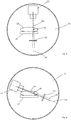
- FIG. 1 shows such a situation.
- a rotatable gantry 10 is set in an upright orientation, perhaps recessed into a wall or projecting through a false wall. It is in the form of a drum, rotatable around a horizontal axis; figure 1 is a view along that axis.
- the gantry 10 carries a radiation source 12 which can emit a collimated beam of therapeutic ionising radiation around a central axis 14, which intersects with the horizontal axis around which the gantry 10 rotates.
- the central axis 14 of the beam sweeps out a vertical plane and approaches the point of intersection (often referred to as the isocentre) from all possible directions.
- the tumour 16 is positioned relative to the beam by placing the patient 18 on a patient support 20.
- This is separate to the gantry, usually supported on a floor in front of the gantry.
- Many modern patient supports offer adjustment in six axes, i.e. three translational axes and three rotational axes. In this way, after the patient 18 has been helped onto the support, their position can be adjusted via the patient support 20 so as to locate the tumour as desired. Some limits will of course be imposed by the range of motion of the patient support 20.
- An EPID 22 is also carried by the gantry 10, located diametrically opposite the radiation source 12 to as to capture an image from the radiation beam after attenuation by the patient 18, as described above. As the gantry rotates, this will rotate with the gantry so as to maintain its position relative to the radiation source 12.
- the EPID could alternatively be carried by a separate structure, arranged to support the EPID in a suitable location opposite the source, but mounting it on the same gantry is likely to be easier and more accurate.
- Figure 1 illustrates a situation as outlined above, in which the tumour 16 is significantly off-centre within the patient 18. With the patient on the patient support 20, the tumour is then away from the central axis 14. The beam can however be collimated to compensate for this, thus producing an off-axis beam 24 which will deliver radiation to the tumour 16. This off-axis beam 24 will miss the EPID 22 if in its usual or default position 26 (shown in dotted lines), so the EPID 22 is manually adjusted into a suitable position as shown.
- the degree of offset of the tumour 16 from the central axis 14 will vary.
- the central axis 14 will be parallel to the vector 28 and the offset will be at a minimum, possibly zero. This means that the EPID 22 in its offset position will no longer capture an image of the beam 24, as shown in figure 2 .
- the beam 14 will leave the active imaging region and strike the edge of the EPID 22; this may damage neighbouring electronic components which are often much more radiation sensitive than the imaging panel itself, and are not intended to be exposed to the therapeutic beam.
- the offset position of beam may track across the full 40 x 40cm beam aperture of the collimator as the gantry rotates.
- Figures 3 and 4 show the alternative, to position the patient off-axis via adjustment of the patient support 20 (or otherwise).
- the tumour is placed at or nearer the isocentre.
- rotation of the gantry 10 leaves the beam 24 still within the effective aperture of the EPID 22.
- such treatment may have to be planned around a limited range of rotational movement of the head in order to prevent collision. This is possible within the bounds of treatment planning, but may lead to a sub-optimal treatment plan.
- the treatment can be interrupted in order to reposition the patient and/or imaging panel, but this will prolong the duration of the treatment session, which is undesirable for the patient and hospital.
- the treatment can be planned with the tumour placed away from the isocentre on the machine, to allow the patient to be positioned centrally, avoid collision risk, and allow use of the full 360° rotation of the source, but the EPID will not be available.
- the tumour can be positioned centrally, but the full range of rotation may not be available, so the treatment may be sub-optimal.
- the MLC leaf positions are adjusted to ensure that the EPID is protected and usable, but this will also affect the treatment and render it sub-optimal.
- Figures 5 and 6 illustrate a further type of radiotherapy apparatus.
- Efforts are currently being made to integrate MRI scanning with radiotherapy; at present CT scanning (usually cone-beam CT) is easily integrated simply by adding a lower-energy diagnostic source to the gantry together with an opposing detector, usually located 90° away from the therapeutic beam and the EPID.
- CT scanning usually cone-beam CT
- an opposing detector usually located 90° away from the therapeutic beam and the EPID.
- the integration of MRI scanning is more complex as a design needs to be found that allows for the substantial magnets required by MRI systems, although once this is done there are benefits in that the background dose of ionising radiation given to the patient is reduced as compared to a CT scan.
- Figures 5 and 6 show such a system; the patient 50 (not shown in figure 6 ) lies on a patient support 52 that can be translated longitudinally into and out of a bore 54.
- a pair of primary magnet windings 56, 58 are arranged concentrically around the bore 54, spaced longitudinally along the central axis 60 of the bore 54 so that each winding extends from a respective end of the bore 54 towards the centre of the bore.
- a gap 62 is left at that centre of the bore between the two windings, and a rotating gantry 64 fits within that gap 62 and is able to rotate around the bore 54.
- a therapeutic source 66 is mounted on the gantry 64 and is therefore rotateable around the bore 54 together with the gantry 64; collimators 68 are provided within the source 66 so that a radiotherapeutic dose can be delivered to the patient 50 in an otherwise known manner.
- An EPID (not shown) is mounted on the gantry 64, opposite the source 66 and is used in a manner corresponding to that of the apparatus of figures 1 to 4 .
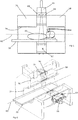
- FIG. 7 shows a radiotherapy apparatus of the same general type as figures 1 to 4 , although the invention is also applicable to apparatus of the type shown in figures 5 and 6 by making a corresponding change.
- a patient 100 is supported on a patient support 102 in front of a gantry 104 that is rotatable around a horizontal axis 106.
- the gantry 104 is in the form of a cylindrical drum resting on its circular face on a number of supporting wheels 108, and driven to rotate by a motor (not shown) that engages with an edge of the drum. The drum thus rotates around its centre, through which the axis 106 passes.
- a radiotherapeutic source 110 is mounted on the drum, offset from its front face 112 by a gantry arm 114.
- the source 110 is aimed towards the rotation axis 106, thus defining an isocentre where the rotation axis 106 meets the central axis of the beam emitted by the source 110.
- a collimator arrangement 116 is included in the radiation source 110 so as to shape the beam as desired and allow the required dose distribution to be built up.
- An EPID 118 is also mounted on the gantry 104, via a gantry arm 120 that extends transversely from the front face 112 of the gantry 104 so as to place the EPID 118 generally opposite the source 110, with the patient 100 and the patient support 102 between them. This allows the EPID 118 to capture an image of the beam as attenuated by the patient 100.
- the EPID 118 is connected to its gantry arm 120 via a series of servo-controlled linkages 122 that allow x-y movement of the EPID 118 relative to the gantry arm 120.
- the two translation axes of the linkages 122 are arranged transverse to the beam direction, so the effect of translating the EPID 118 is to scan it across the field of the beam.
- the gantry arm 120 and/or the linkages 122 may be also able to move the EPID 118 in a z-direction, i.e. towards or away from the source 110.
- a z-direction i.e. towards or away from the source 110.
- motion in the z direction is in principle irrelevant to the invention apart from its influence on the effective image size within the beam aperture.
- the movement of the EPID 118 in the y direction (i.e. parallel to the rotation axis 106) will usually be in a straight line. Its movement in the x direction (i.e. perpendicular to both the rotation axis 106 and the beam axis, into and out of the page in figure 7 ) is ideally along a circular path centred on the rotation axis 106, in order to maintain a fixed distance from the source 110.
- movement in a straight line will be a good first approximation to circular movement, especially for smaller translational movements. It is likely that correction of the images to account for the difference between circular and linear movement will be straightforward.
- Figure 8 shows the control schema for the apparatus of figure 7 .
- a physician prepares a prescription 124 setting out a dose and a dose distribution that are to be delivered to the patient.
- a separate document 126 sets out the delivery limitations imposed by the apparatus to be used, such as the resolution of the collimators, speed of collimator movement and gantry movement, the dose characteristics of the beam, etc.
- a treatment planning computer 128 processes the prescription and the machine characteristics according to known computational methods, to produce a treatment plan 130. This sets out a sequence of gantry movements, collimator movements, beam intensities etc. which the apparatus can then follow in order to create a dose distribution in the patient which corresponds to the prescription.
- This treatment plan 130 is then passed to the apparatus control unit 132.
- the control unit 132 is arranged to control the gantry drive motor 134, the radiation source 136, and the multi-leaf collimator ("MLC") drives 138.
- MLC multi-leaf collimator
- the apparatus control unit 132 may comprise several sub-modules, each attending to different functional aspects of the apparatus, which may be distributed around the apparatus as required.
- FIG 8 Also shown in figure 8 is a link from the apparatus control unit 132 to the servo drive motors 140 of the EPID linkages 122 ( figure 7 ), thus allowing the apparatus control unit to control the x-y position of the EPID 118.
- This control can be done in one of two ways.
- a first way is to predict the necessary EPID movements and adjust it accordingly.
- the treatment planning computer 128 can use its a priori knowledge of the collimator positions during the treatment to calculate the required position of the EPID 118 at each point during the treatment. This can be done using simple ray projection methods, either to determine where the beam will fall in the plane containing the EPID, or to determine a correlation between EPID positions and MLC leaves and positions, from either of which the necessary EPID position for each collimator shape during the treatment can be determined.
- the system can either issue a warning to the clinician or can incorporate the EPID size as an apparatus limitation within document 126 and then calculate or re-calculate the treatment plan, as necessary.
- the EPID positions during treatment that are determined in this way can then be incorporated into the treatment plan 130 and passed to the apparatus control unit 132.
- the apparatus control unit 132 can then control the EPID drive motors 140 as required in order to achieve this.
- Adjustments to the planned EPID positions may of course be needed in view of any adjustments made to the planned collimator positions, such as to compensate for movement of the target.
- the EPID position calculations could be done by a separate module within the treatment planning computer 128, or by a different computing element, or by the apparatus control unit 132. In the latter case, the necessary EPID positions could be calculated in real time while acting on the collimator positions contained in the treatment plan.
- the alternative control mechanism for the EPID drive motors is a reactive feedback method which uses the images obtained from the EPID in order to determine a necessary movement.
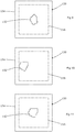
- Figure 9 shows an image 150 obtained from the EPID; the predominant feature in the EPID is the shape 152 of the beam as shaped by the multi-leaf collimator. Outside this outline 152, the image is essentially dark other than any inevitable leakage; within this outline there will be information as to the attenuation by the patient, but for the purposes of clarity this detail is omitted from figures 9 to 11 .
- the beam shape 152 is in the centre of the EPID aperture 154 and so no action needs to be taken.
- the beam shape 152 may well move as shown in figure 10 .
- the apparatus control unit 132 therefore monitors the image 150 to detect when the beam shape 152 reaches the edge of a pre-defined margin 156 around the edge of the image.
- Figure 10 shows that the beam shape 152 has moved sufficient to touch the edge of the margin 156 at 158.
- the apparatus control unit 132 therefore instructs the servo drive motors 140 of the EPID linkages 122 to move the EPID in the appropriate direction(s) to bring the beam shape 152 back to the centre of the image as shown in figure 11 .
- a negative feedback loop is created which serves to keep the beam shape 152 within the bounds of the image 150, responding both to gross movements of the beam shape (such as following rotation around an offset target) and to changes in the beam shape that take it towards an edge (such as due to reconfiguration of the collimator shape).
- the margin 156 is quite narrow.
- the choice of margin size will be a balance between factors, to be assessed by the skilled person.
- a narrow margin will reduce the number of movements of the EPID, thus reducing wear on the EPID drive motors and (possibly) reducing the complexity of correcting the images for position, but will require faster movement of the EPID and less lag in initiating movement.
- a larger margin means that the EPID drive motors need not react as promptly or move as quickly, but raises the possibility of very large beam shapes causing problems if they approach the margin on two or more sides.
- One possibility is a variable margin, chosen according to how large the beam shape is, with smaller beam shapes implying a larger margin and large beam shapes prompting a relaxation of the margin size.
- the EPID position is ideally recorded during the treatment, such as in conjunction with the images obtained from it. This then allows the images to be corrected for the EPID offset.
- the images could be processed in real time by offsetting them against (say) a plain background by an amount corresponding to the EPID offset when they were captured. The saved set of images are then in a comparable format for later analysis.
- the present invention allows the EPID to be used for real-time diagnostic purposes, regardless of the type of treatment, and without having to make potentially detrimental adjustments to the treatment plan. It will of course be understood that many variations may be made to the above-described embodiment without departing from the scope of the present invention.
Abstract
Description
- The present invention seeks to improve upon existing methods of portal imaging during radiotherapy treatment.
- Radiotherapy is the treatment of lesions such as tumours with ionising radiation such as high-energy x-rays. The radiation interferes with cellular processes within the tumour and can lead to cellular death. To spare healthy tissue (such as skin or organs adjacent to the tumour, or through which the radiation needs to pass in order to treat the tumour), shaped radiation beams are aimed from several different angles to intersect at the tumour, thus delivering a peak dose in the tumour region and a lower dose elsewhere.
- To allow delivery of the radiation from several angles, the radiation source is usually mounted on the end of a cantilever arm projecting out from a rotatable gantry. The gantry has an axis of rotation that is horizontal, and the radiation source has a field of view whose central axis is perpendicular to and intersects with the axis of rotation. Thus, the point of intersection or "isocentre" remains within the field of view of the source at all times, and the direction of the radiation beam rotates around the isocentre.
- To shape the radiation beam, collimators are provided. These usually include one or more multi-leaf collimators (MLCs), which collimate the radiation field into the required shape by moving each of a number of long, narrow side-by-side leaves so that the tips of the leaves define the intended shape. Prior to radiotherapy, a treatment plan will usually be calculated based on the parameters of the radiotherapy apparatus and the desired three-dimensional dose distribution, which consists of a series of dose segments each characterised by a beam direction, beam shape (i.e. specific collimator positions) and dosage.
- Portal images are images of the therapeutic radiation taken after attenuation by the patient, usually by capturing the image in a plate that is located on the opposite side of the patient to the radiation source. Thus, the radiation passes through the patient and then reaches the portal imager. Although the contrast in a portal image is relatively poor due to the nature of the high-energy x-radiation that is used for radiotherapy, the image is still useful. It is possible to discern some features of the patient anatomy in order to determine correct positioning, the overall shape of the radiation field is visible and provides a check of collimator function and field shape & size, and the attenuation (i.e. the difference between the observed radiation intensity after the patient and the known radiation intensity emitted towards the patient) gives information as to the dose actually received by the patient. All of these can be compared to that which was expected during the treatment planning stage.
- Portal images were originally captured using port films, i.e. photographic plates. These films would serve as a record of the field shape, and if anatomy could be seen in the field then it could be also used to verify the position of the beam relative to the patient's anatomy. Electronic Portal Imaging Devices ("EPIDs") have now been in use for some time in preference to port films, as they have better sensitivity than films and allow the images to be collected and stored electronically. An EPID is now a well-established part of radiotherapy delivery.
- Because EPIDs are now quite common on modern radiotherapy equipment, a number of uses for EPIDs have been developed that go beyond the original port-film single exposure use. This includes portal dosimetry (noted above) which attempts to recalculate the patient dose by a method such as back projection, in order to check the end to end QA process. Another example is the capturing of video images showing the dynamic movement of the MLC leaves. All these uses are possible with existing EPID hardware.
- However, these new uses do have a limitation in that the field size of current EPIDs is smaller than the field sizes of most MLCs. For example, a typical MLC has a 40 x 40 cm field size when referenced to the isocentre, whereas a typical state-of-the-art EPID has a panel giving an effective image size of 26 x 26 cm at isocentre, and some EPIDs are smaller still (all dimensions being referenced to the isocentre). This is rarely a problem in obtaining an image of the treatment, however, because large field sizes are uncommon and so will usually fall onto the panel within its limits. Where the desired image is of an offset field, the panel can be manually adjusted to provide a corresponding offset.
-
US2007/0195936A1 discloses an arrangement in which the field size is checked to ensure that the EPID aperture will not be exceeded, and moves the MLC leaves as necessary in order to keep the beam shape within the confines of the EPID panel. - The present invention provides a radiotherapy apparatus comprising a source arranged to emit a beam of therapeutic radiation, and an imaging device for the therapeutic radiation, the source being movable to direct the beam towards a location from a plurality of directions and the imaging device being movable relative to the source, and a control unit arranged to co-ordinate the movement of both to ensure that the imaging device remains in the beam, as the source moves to different treatment positions.
- The source typically produces the beam along an axis, with the beam covering a maximum aperture of the source. The imaging device is ideally located opposite the source, with the patient support generally between the source and the imaging device. The radiotherapy apparatus preferably also comprises a collimator for collimating the beam to produce a collimated beam covering a sub-part of the maximum aperture, a patient support positionable in the path of the beam, a rotatable gantry, on which the source is mounted, for rotating the source around the patient support thereby to deliver the beam from a range of directions, with the imaging device mounted on the gantry via a drive member allowing translational motion of the imaging device in at least one direction perpendicular to the axis, and a control unit adapted to control the drive member to move the imaging device within the maximum aperture and maintain coincidence between the imaging device and the sub-part of the maximum aperture.
- Accordingly, the EPID can be moved during the treatment in order to maintain the collimated field of the radiation beam within the bounds of the EPID. This ensures that the image is valid and prevents damage to the EPID as a result of exposure of more sensitive (or less shielded) parts to the beam. No restrictions need be placed on the positioning of the patient, meaning that she or he can be positioned as desired. The treatment can be unaffected, unlike the suggestion made in
US2007/0195936A1 . - There are various ways that the movement of the EPID can be controlled. One option is for the control unit to receive a treatment plan containing instructions for at least movement of the rotatable gantry, movement of the collimator, activation of the source, and movement of the drive member. In other words, alongside calculations of the necessary beam shapes and intensities over time, a treatment planning computer can also model the beam shape and position through the treatment (once the treatment is decided) and establish the EPID movements that will be needed in order to allow for that.
- An alternative is to adjust the EPID position in real time during treatment. The control unit will then receive an output image from the imaging device and adjust the position of the imaging device in reliance on that image. Thus, for example, if a distance in the output image between an image of the collimated beam and an edge of the output image is less than a threshold, the control unit will instruct a movement of the drive member.
- The gantry can be a rotatable drum, in which case the source can be attached to the gantry via an arm extending transversely to the drum, preferably with the beam axis coincident with a rotation axis of the gantry.
- Alternatively, the gantry can comprise a circular path around which the source and the imaging device can travel, the axis of the source being directed to the centre of the circular path.
- An embodiment of the present invention will now be described by way of example, with reference to the accompanying figures in which;
-
Figures 1 and 2 show a conventional radiotherapy apparatus in different rotational states; -
Figures 3 and 4 show the radiotherapy apparatus offigures 1 and 2 in an alternative configuration; -
Figures 5 and 6 show an alternative radiotherapy apparatus; -
Figure 7 shows a radiotherapy apparatus according to the present invention; -
Figure 8 shows a control schema for the radiotherapy apparatus offigure 7 ; and -
Figures 9 to 11 show portal images derived from the apparatus offigure 7 . - As noted above, the field size of current EPIDs is smaller than the maximum apertures of most MLCs, although larger than most actual dose shapes. We have realised that this limitation becomes a problem when the EPID is used for portal dosimetry or to capture a dynamic MLC video under certain treatment conditions. As an example, we propose to discuss a volumetric modulated arc therapy (VMAT) delivery to an off-axis target such as a tumour present in one breast or lung. This is not the only example, however, and the invention is applicable in other contexts.
-
Figure 1 shows such a situation. Arotatable gantry 10 is set in an upright orientation, perhaps recessed into a wall or projecting through a false wall. It is in the form of a drum, rotatable around a horizontal axis;figure 1 is a view along that axis. Thegantry 10 carries aradiation source 12 which can emit a collimated beam of therapeutic ionising radiation around acentral axis 14, which intersects with the horizontal axis around which thegantry 10 rotates. As thegantry 10 rotates and carries thesource 12 around, thecentral axis 14 of the beam sweeps out a vertical plane and approaches the point of intersection (often referred to as the isocentre) from all possible directions. This forms the basis of a radiotherapy treatment; by placing the tumour or other lesion at the isocentre and irradiating the tumour from a range of directions, a dose can be delivered to the tumour which is substantially greater than the dose delivered to tissue around the tumour. - The
tumour 16 is positioned relative to the beam by placing the patient 18 on apatient support 20. This is separate to the gantry, usually supported on a floor in front of the gantry. Many modern patient supports offer adjustment in six axes, i.e. three translational axes and three rotational axes. In this way, after thepatient 18 has been helped onto the support, their position can be adjusted via thepatient support 20 so as to locate the tumour as desired. Some limits will of course be imposed by the range of motion of thepatient support 20. - An
EPID 22 is also carried by thegantry 10, located diametrically opposite theradiation source 12 to as to capture an image from the radiation beam after attenuation by thepatient 18, as described above. As the gantry rotates, this will rotate with the gantry so as to maintain its position relative to theradiation source 12. The EPID could alternatively be carried by a separate structure, arranged to support the EPID in a suitable location opposite the source, but mounting it on the same gantry is likely to be easier and more accurate. -
Figure 1 illustrates a situation as outlined above, in which thetumour 16 is significantly off-centre within thepatient 18. With the patient on thepatient support 20, the tumour is then away from thecentral axis 14. The beam can however be collimated to compensate for this, thus producing an off-axis beam 24 which will deliver radiation to thetumour 16. This off-axis beam 24 will miss theEPID 22 if in its usual or default position 26 (shown in dotted lines), so theEPID 22 is manually adjusted into a suitable position as shown. - However, as the gantry rotates (
figure 2 ) and the patient 18 remains stationary on thepatient support 20, the degree of offset of thetumour 16 from thecentral axis 14 will vary. Considered geometrically, there will be avector 28 from the isocentre to the tumour, and when thecentral axis 14 is perpendicular to the vector 28 (as infigure 1 ) then the offset as viewed along the central axis will be at is maximum. Equally, after a 90° rotation(as infigure 2 ), thecentral axis 14 will be parallel to thevector 28 and the offset will be at a minimum, possibly zero. This means that theEPID 22 in its offset position will no longer capture an image of thebeam 24, as shown infigure 2 . In addition, at some point in the rotation between the states shown infigures 1 and 2 , thebeam 14 will leave the active imaging region and strike the edge of theEPID 22; this may damage neighbouring electronic components which are often much more radiation sensitive than the imaging panel itself, and are not intended to be exposed to the therapeutic beam. - Thus, although the actual field size (projected to isocentre) is likely to be smaller than the 26 x 26cm aperture of the
EPID 22, the offset position of beam may track across the full 40 x 40cm beam aperture of the collimator as the gantry rotates. Thus, if the EPID is being used to collect portal dosimetry data, then some data will be lost and this will compromise the ability to accurately calculate the portal dose, as well as potentially causing damage to the EPID. -
Figures 3 and 4 show the alternative, to position the patient off-axis via adjustment of the patient support 20 (or otherwise). Thus, the tumour is placed at or nearer the isocentre. As shown infigure 3 , this means that distance between the isocentre and thetumour 16 is small, and theEPID 22 does not need to be offset. As shown infigure 4 , rotation of thegantry 10 leaves thebeam 24 still within the effective aperture of theEPID 22. However, this raises a risk of collision between theradiation head 12 rotating around thepatient support 20 and the off-axis patient support 20. Any further rotation in an anticlockwise direction beyond that shown infigure 4 will lead to a collision and possible injury to the patient, as well as damage to the apparatus. As a result, such treatment may have to be planned around a limited range of rotational movement of the head in order to prevent collision. This is possible within the bounds of treatment planning, but may lead to a sub-optimal treatment plan. Alternatively, the treatment can be interrupted in order to reposition the patient and/or imaging panel, but this will prolong the duration of the treatment session, which is undesirable for the patient and hospital. - So, the treatment can be planned with the tumour placed away from the isocentre on the machine, to allow the patient to be positioned centrally, avoid collision risk, and allow use of the full 360° rotation of the source, but the EPID will not be available. Alternatively, the tumour can be positioned centrally, but the full range of rotation may not be available, so the treatment may be sub-optimal. In a further alternative, according to
US2007/0195936A1 , the MLC leaf positions are adjusted to ensure that the EPID is protected and usable, but this will also affect the treatment and render it sub-optimal. -
Figures 5 and 6 illustrate a further type of radiotherapy apparatus. Efforts are currently being made to integrate MRI scanning with radiotherapy; at present CT scanning (usually cone-beam CT) is easily integrated simply by adding a lower-energy diagnostic source to the gantry together with an opposing detector, usually located 90° away from the therapeutic beam and the EPID. The integration of MRI scanning is more complex as a design needs to be found that allows for the substantial magnets required by MRI systems, although once this is done there are benefits in that the background dose of ionising radiation given to the patient is reduced as compared to a CT scan.Figures 5 and 6 show such a system; the patient 50 (not shown infigure 6 ) lies on apatient support 52 that can be translated longitudinally into and out of abore 54. A pair ofprimary magnet windings bore 54, spaced longitudinally along thecentral axis 60 of thebore 54 so that each winding extends from a respective end of thebore 54 towards the centre of the bore. Agap 62 is left at that centre of the bore between the two windings, and arotating gantry 64 fits within thatgap 62 and is able to rotate around thebore 54. Atherapeutic source 66 is mounted on thegantry 64 and is therefore rotateable around thebore 54 together with thegantry 64;collimators 68 are provided within thesource 66 so that a radiotherapeutic dose can be delivered to the patient 50 in an otherwise known manner. An EPID (not shown) is mounted on thegantry 64, opposite thesource 66 and is used in a manner corresponding to that of the apparatus offigures 1 to 4 . - An apparatus of this type presents additional difficulties, in that where the target is offset it will not generally be possible to offset the patient as shown in
figures 3 and 4 , as the patient must be located within the defined bore 54 and cannot be displaced significantly. Therefore, the only option is to offset the beam by use of thecollimator 68, leading to the difficulties illustrated in relation tofigures 1 and 2 . - Both problems can be addressed using the apparatus of
figure 7 in conjunction with the control schema offigure 8. Figure 7 shows a radiotherapy apparatus of the same general type asfigures 1 to 4 , although the invention is also applicable to apparatus of the type shown infigures 5 and 6 by making a corresponding change. Thus, apatient 100 is supported on apatient support 102 in front of agantry 104 that is rotatable around ahorizontal axis 106. In practice, thegantry 104 is in the form of a cylindrical drum resting on its circular face on a number of supportingwheels 108, and driven to rotate by a motor (not shown) that engages with an edge of the drum. The drum thus rotates around its centre, through which theaxis 106 passes. - A
radiotherapeutic source 110 is mounted on the drum, offset from itsfront face 112 by agantry arm 114. Thesource 110 is aimed towards therotation axis 106, thus defining an isocentre where therotation axis 106 meets the central axis of the beam emitted by thesource 110. Acollimator arrangement 116 is included in theradiation source 110 so as to shape the beam as desired and allow the required dose distribution to be built up. - An
EPID 118 is also mounted on thegantry 104, via agantry arm 120 that extends transversely from thefront face 112 of thegantry 104 so as to place theEPID 118 generally opposite thesource 110, with thepatient 100 and thepatient support 102 between them. This allows theEPID 118 to capture an image of the beam as attenuated by thepatient 100. TheEPID 118 is connected to itsgantry arm 120 via a series of servo-controlledlinkages 122 that allow x-y movement of theEPID 118 relative to thegantry arm 120. The two translation axes of thelinkages 122 are arranged transverse to the beam direction, so the effect of translating theEPID 118 is to scan it across the field of the beam. Thegantry arm 120 and/or thelinkages 122 may be also able to move theEPID 118 in a z-direction, i.e. towards or away from thesource 110. However, for the purposes of the present invention we are principally concerned with movement in the x and y directions; motion in the z direction is in principle irrelevant to the invention apart from its influence on the effective image size within the beam aperture. - The movement of the
EPID 118 in the y direction (i.e. parallel to the rotation axis 106) will usually be in a straight line. Its movement in the x direction (i.e. perpendicular to both therotation axis 106 and the beam axis, into and out of the page infigure 7 ) is ideally along a circular path centred on therotation axis 106, in order to maintain a fixed distance from thesource 110. However, for ease of manufacture it is likely that movement in a straight line will be a good first approximation to circular movement, especially for smaller translational movements. It is likely that correction of the images to account for the difference between circular and linear movement will be straightforward. -
Figure 8 shows the control schema for the apparatus offigure 7 . A physician prepares aprescription 124 setting out a dose and a dose distribution that are to be delivered to the patient. Aseparate document 126 sets out the delivery limitations imposed by the apparatus to be used, such as the resolution of the collimators, speed of collimator movement and gantry movement, the dose characteristics of the beam, etc. Atreatment planning computer 128 processes the prescription and the machine characteristics according to known computational methods, to produce atreatment plan 130. This sets out a sequence of gantry movements, collimator movements, beam intensities etc. which the apparatus can then follow in order to create a dose distribution in the patient which corresponds to the prescription. Thistreatment plan 130 is then passed to theapparatus control unit 132. Thecontrol unit 132 is arranged to control thegantry drive motor 134, theradiation source 136, and the multi-leaf collimator ("MLC") drives 138. Thus, once initiated by a clinician, theapparatus control unit 132 can deliver the radiotherapy treatment. - In practice, the
apparatus control unit 132 may comprise several sub-modules, each attending to different functional aspects of the apparatus, which may be distributed around the apparatus as required. - Also shown in
figure 8 is a link from theapparatus control unit 132 to theservo drive motors 140 of the EPID linkages 122 (figure 7 ), thus allowing the apparatus control unit to control the x-y position of theEPID 118. This permits theapparatus control unit 132 to adjust the position of the EPID within the beam aperture so as to maintain the beam within the bounds of the EPID, thus obtaining an accurate image of the attenuated beam and also protecting the EPID from the beam. This control can be done in one of two ways. - A first way is to predict the necessary EPID movements and adjust it accordingly. Accordingly, the
treatment planning computer 128 can use its a priori knowledge of the collimator positions during the treatment to calculate the required position of theEPID 118 at each point during the treatment. This can be done using simple ray projection methods, either to determine where the beam will fall in the plane containing the EPID, or to determine a correlation between EPID positions and MLC leaves and positions, from either of which the necessary EPID position for each collimator shape during the treatment can be determined. If a collimator shape is called for during treatment that is so large or unusual that the EPID cannot accommodate it, then the system can either issue a warning to the clinician or can incorporate the EPID size as an apparatus limitation withindocument 126 and then calculate or re-calculate the treatment plan, as necessary. The EPID positions during treatment that are determined in this way can then be incorporated into thetreatment plan 130 and passed to theapparatus control unit 132. During the treatment, theapparatus control unit 132 can then control theEPID drive motors 140 as required in order to achieve this. Adjustments to the planned EPID positions may of course be needed in view of any adjustments made to the planned collimator positions, such as to compensate for movement of the target. - Of course, the EPID position calculations could be done by a separate module within the
treatment planning computer 128, or by a different computing element, or by theapparatus control unit 132. In the latter case, the necessary EPID positions could be calculated in real time while acting on the collimator positions contained in the treatment plan. - The alternative control mechanism for the EPID drive motors is a reactive feedback method which uses the images obtained from the EPID in order to determine a necessary movement. This is shown in
figures 9 to 11. Figure 9 shows animage 150 obtained from the EPID; the predominant feature in the EPID is theshape 152 of the beam as shaped by the multi-leaf collimator. Outside thisoutline 152, the image is essentially dark other than any inevitable leakage; within this outline there will be information as to the attenuation by the patient, but for the purposes of clarity this detail is omitted fromfigures 9 to 11 . Infigure 9 , thebeam shape 152 is in the centre of theEPID aperture 154 and so no action needs to be taken. - As the treatment progresses, with rotation of the gantry and adjustment of the collimator shape, the
beam shape 152 may well move as shown infigure 10 . Theapparatus control unit 132 therefore monitors theimage 150 to detect when thebeam shape 152 reaches the edge of apre-defined margin 156 around the edge of the image.Figure 10 shows that thebeam shape 152 has moved sufficient to touch the edge of themargin 156 at 158. Theapparatus control unit 132 therefore instructs theservo drive motors 140 of theEPID linkages 122 to move the EPID in the appropriate direction(s) to bring thebeam shape 152 back to the centre of the image as shown infigure 11 . In this way, a negative feedback loop is created which serves to keep thebeam shape 152 within the bounds of theimage 150, responding both to gross movements of the beam shape (such as following rotation around an offset target) and to changes in the beam shape that take it towards an edge (such as due to reconfiguration of the collimator shape). - As illustrated in
figures 9 to 11 , themargin 156 is quite narrow. In practice, the choice of margin size will be a balance between factors, to be assessed by the skilled person. A narrow margin will reduce the number of movements of the EPID, thus reducing wear on the EPID drive motors and (possibly) reducing the complexity of correcting the images for position, but will require faster movement of the EPID and less lag in initiating movement. Equally, a larger margin means that the EPID drive motors need not react as promptly or move as quickly, but raises the possibility of very large beam shapes causing problems if they approach the margin on two or more sides. One possibility is a variable margin, chosen according to how large the beam shape is, with smaller beam shapes implying a larger margin and large beam shapes prompting a relaxation of the margin size. - In either case, the EPID position is ideally recorded during the treatment, such as in conjunction with the images obtained from it. This then allows the images to be corrected for the EPID offset. Alternatively, the images could be processed in real time by offsetting them against (say) a plain background by an amount corresponding to the EPID offset when they were captured. The saved set of images are then in a comparable format for later analysis.
- Accordingly, the present invention allows the EPID to be used for real-time diagnostic purposes, regardless of the type of treatment, and without having to make potentially detrimental adjustments to the treatment plan. It will of course be understood that many variations may be made to the above-described embodiment without departing from the scope of the present invention.
Claims (8)
- A radiotherapy apparatus comprising a source arranged to emit a beam of therapeutic radiation and an imaging device for the therapeutic radiation, the source being movable to direct the beam towards a location from a plurality of directions and the imaging device being movable relative to the source, and a control unit arranged to co-ordinate the movement of both to ensure that the imaging device remains in the beam, as the source moves to different treatment positions.
- A radiotherapy apparatus according to claim 1, in which the source produces the beam along an axis, the beam covering a maximum aperture of the source, and the imaging device is located opposite the source and with the patient support generally between the source and the imaging device;further comprising;a collimator for collimating the beam to produce a collimated beam covering a sub-part of the maximum aperture;a patient support positionable in the path of the beam;a rotatable gantry, on which the source and the imaging device are mounted, for rotating the source around the patient support thereby to deliver the beam from a range of directions;the imaging device is mounted on the gantry via a drive member allowing translational motion of the imaging device in at least one direction perpendicular to the axis;a control unit adapted to control the drive member to move the imaging device within the maximum aperture and maintain coincidence between the imaging device and the sub-part of the maximum aperture.
- A radiotherapy apparatus according to claim 2 in which the control unit receives a treatment plan containing instructions for;i. movement of the rotatable gantryii. movement of the collimatoriii. activation of the source, andiv. movement of the drive member.
- A radiotherapy apparatus according to claim 2 further adapted to analyse an output image from the imaging device and, if a distance in the output image between an image of the collimated beam and an edge of the output image is less than a threshold, instructs a movement of the drive member.
- A radiotherapy apparatus according to any one of claims 1 to 4 in which the gantry is a rotatable drum.
- A radiotherapy apparatus according to claim 5 in which the source is attached to the gantry via an arm extending transversely to the drum.
- A radiotherapy apparatus according to any one of claims 2 to 6 in which the beam axis co-incides with a rotation axis of the gantry.
- A radiotherapy apparatus according to any one of claims 2 to 7 in which the gantry comprises a circular path around which the source and the imaging device can travel, the axis of the source being directed to the centre of the circular path.
Applications Claiming Priority (2)
| Application Number | Priority Date | Filing Date | Title |
|---|---|---|---|
| GB1416055.0A GB2530060B (en) | 2014-09-11 | 2014-09-11 | Portal imaging during radiotherapy |
| EP15183347.2A EP2995347B1 (en) | 2014-09-11 | 2015-09-01 | Portal imaging during radiotherapy |
Related Parent Applications (2)
| Application Number | Title | Priority Date | Filing Date |
|---|---|---|---|
| EP15183347.2A Division EP2995347B1 (en) | 2014-09-11 | 2015-09-01 | Portal imaging during radiotherapy |
| EP15183347.2A Division-Into EP2995347B1 (en) | 2014-09-11 | 2015-09-01 | Portal imaging during radiotherapy |
Publications (2)
| Publication Number | Publication Date |
|---|---|
| EP3300770A1 true EP3300770A1 (en) | 2018-04-04 |
| EP3300770B1 EP3300770B1 (en) | 2024-01-10 |
Family
ID=51869440
Family Applications (2)
| Application Number | Title | Priority Date | Filing Date |
|---|---|---|---|
| EP17197721.8A Active EP3300770B1 (en) | 2014-09-11 | 2015-09-01 | Portal imaging during radiotherapy |
| EP15183347.2A Active EP2995347B1 (en) | 2014-09-11 | 2015-09-01 | Portal imaging during radiotherapy |
Family Applications After (1)
| Application Number | Title | Priority Date | Filing Date |
|---|---|---|---|
| EP15183347.2A Active EP2995347B1 (en) | 2014-09-11 | 2015-09-01 | Portal imaging during radiotherapy |
Country Status (4)
| Country | Link |
|---|---|
| US (1) | US11033756B2 (en) |
| EP (2) | EP3300770B1 (en) |
| CN (1) | CN105413067B (en) |
| GB (1) | GB2530060B (en) |
Cited By (1)
| Publication number | Priority date | Publication date | Assignee | Title |
|---|---|---|---|---|
| WO2021219830A1 (en) * | 2020-04-29 | 2021-11-04 | Elekta Limited | Patient positioning for radiotherapy treatment |
Families Citing this family (8)
| Publication number | Priority date | Publication date | Assignee | Title |
|---|---|---|---|---|
| WO2018023344A1 (en) * | 2016-08-01 | 2018-02-08 | 深圳市奥沃医学新技术发展有限公司 | Radiation therapy apparatus and beam imaging method |
| US10201719B2 (en) * | 2017-03-30 | 2019-02-12 | Varian Medical Systems Particle Therapy Gmbh | Gantry system for particle beam therapy |
| CN209392611U (en) * | 2018-05-25 | 2019-09-17 | 深圳市奥沃医学新技术发展有限公司 | The support arm and radiotherapy apparatus of electronic portal image device |
| DE102018008806A1 (en) * | 2018-11-09 | 2020-05-14 | Städtisches Klinikum Dessau | Procedure for the authenticity-related correction of the spatial position of the central beam of radiation therapy devices and the patient position |
| CN109646819A (en) * | 2018-12-29 | 2019-04-19 | 佛山瑞加图医疗科技有限公司 | A kind of accelerator beat bracket |
| CN109646820A (en) * | 2018-12-29 | 2019-04-19 | 佛山瑞加图医疗科技有限公司 | Accelerator head liftable regulating device, radiotherapy apparatus and control method |
| GB2585887B (en) * | 2019-07-19 | 2021-11-03 | Elekta ltd | Collision avoidance in radiotherapy |
| GB2602355B (en) * | 2020-12-24 | 2023-07-12 | Elekta ltd | Devices and methods for delivering non-coplanar radiotherapy |
Citations (5)
| Publication number | Priority date | Publication date | Assignee | Title |
|---|---|---|---|---|
| EP1308185A2 (en) * | 2001-11-02 | 2003-05-07 | Siemens Medical Solutions USA, Inc. | System and method for measuring beam quality and dosimetry using electronic portal imaging |
| US20040024300A1 (en) * | 2001-11-02 | 2004-02-05 | Graf Ulrich Martin | Radiotherapy apparatus equipped with an articulable gantry for positioning an imaging unit |
| WO2006013325A1 (en) * | 2004-08-05 | 2006-02-09 | Elekta Ab (Publ) | X-ray apparatus |
| US20090283682A1 (en) * | 2008-05-19 | 2009-11-19 | Josh Star-Lack | Multi-energy x-ray imaging |
| CN203694429U (en) * | 2014-01-06 | 2014-07-09 | 山东新华医疗器械股份有限公司 | Linear driving assembly of electron portal imaging device |
Family Cites Families (7)
| Publication number | Priority date | Publication date | Assignee | Title |
|---|---|---|---|---|
| US6725035B2 (en) * | 1992-03-06 | 2004-04-20 | Aircell Inc. | Signal translating repeater for enabling a terrestrial mobile subscriber station to be operable in a non-terrestrial environment |
| US6345114B1 (en) * | 1995-06-14 | 2002-02-05 | Wisconsin Alumni Research Foundation | Method and apparatus for calibration of radiation therapy equipment and verification of radiation treatment |
| US6810108B2 (en) * | 2001-11-02 | 2004-10-26 | Siemens Medical Solutions Usa, Inc. | System and method for positioning an electronic portal imaging device |
| WO2004105574A2 (en) * | 2003-05-21 | 2004-12-09 | William Beaumont Hospital | Image guided radiation therapy |
| US7564950B2 (en) * | 2006-02-17 | 2009-07-21 | Siemens Medical Solutions Usa, Inc. | Multi-leaf collimator based field size clipping for automatic adaptation to allowed image area |
| JP2011189016A (en) * | 2010-03-15 | 2011-09-29 | Japan Synchrotron Radiation Research Inst | Radiotherapy apparatus and method of acquiring irradiation field confirmation image of radiotherapy apparatus |
| DE102010026674B4 (en) * | 2010-07-09 | 2012-09-27 | Siemens Aktiengesellschaft | Imaging device and radiotherapy device |
-
2014
- 2014-09-11 GB GB1416055.0A patent/GB2530060B/en active Active
-
2015
- 2015-09-01 EP EP17197721.8A patent/EP3300770B1/en active Active
- 2015-09-01 EP EP15183347.2A patent/EP2995347B1/en active Active
- 2015-09-10 CN CN201510715664.0A patent/CN105413067B/en active Active
- 2015-09-11 US US14/851,527 patent/US11033756B2/en active Active
Patent Citations (5)
| Publication number | Priority date | Publication date | Assignee | Title |
|---|---|---|---|---|
| EP1308185A2 (en) * | 2001-11-02 | 2003-05-07 | Siemens Medical Solutions USA, Inc. | System and method for measuring beam quality and dosimetry using electronic portal imaging |
| US20040024300A1 (en) * | 2001-11-02 | 2004-02-05 | Graf Ulrich Martin | Radiotherapy apparatus equipped with an articulable gantry for positioning an imaging unit |
| WO2006013325A1 (en) * | 2004-08-05 | 2006-02-09 | Elekta Ab (Publ) | X-ray apparatus |
| US20090283682A1 (en) * | 2008-05-19 | 2009-11-19 | Josh Star-Lack | Multi-energy x-ray imaging |
| CN203694429U (en) * | 2014-01-06 | 2014-07-09 | 山东新华医疗器械股份有限公司 | Linear driving assembly of electron portal imaging device |
Cited By (1)
| Publication number | Priority date | Publication date | Assignee | Title |
|---|---|---|---|---|
| WO2021219830A1 (en) * | 2020-04-29 | 2021-11-04 | Elekta Limited | Patient positioning for radiotherapy treatment |
Also Published As
| Publication number | Publication date |
|---|---|
| GB2530060B (en) | 2020-12-09 |
| US11033756B2 (en) | 2021-06-15 |
| EP3300770B1 (en) | 2024-01-10 |
| GB2530060A (en) | 2016-03-16 |
| CN105413067A (en) | 2016-03-23 |
| EP2995347B1 (en) | 2018-03-21 |
| EP2995347A1 (en) | 2016-03-16 |
| GB201416055D0 (en) | 2014-10-29 |
| CN105413067B (en) | 2020-11-24 |
| US20160074673A1 (en) | 2016-03-17 |
Similar Documents
| Publication | Publication Date | Title |
|---|---|---|
| EP2995347B1 (en) | Portal imaging during radiotherapy | |
| US11673004B2 (en) | X-ray imaging system with a combined filter and collimator positioning mechanism | |
| US10022563B2 (en) | Image-guided radiotherapy | |
| US8542797B2 (en) | Radiotherapy apparatus configured to track a motion of a target region using a combination of a multileaf collimator and a patient support | |
| US8519370B2 (en) | Modifying radiation beam shapes | |
| US7502443B1 (en) | Radiation therapy machine with triple KV/MV imaging | |
| US8964937B2 (en) | Methods and systems in radiotherapy | |
| US10500420B2 (en) | Small beam area, mid-voltage radiotherapy system with reduced skin dose, reduced scatter around the treatment volume, and improved overall accuracy | |
| EP2946808A1 (en) | Therapy planning device, system for planned therapy, method for making therapy plan, and program | |
| EP3639892B1 (en) | Radiotherapy system and operating method | |
| WO2004105574A2 (en) | Image guided radiation therapy | |
| US20140114114A1 (en) | Systems and methods for the management and provision of radiotherapy | |
| CN117835912A (en) | Multi-modal radiation apparatus and method | |
| GB2522914A (en) | Image guided radiotherapy | |
| US7564950B2 (en) | Multi-leaf collimator based field size clipping for automatic adaptation to allowed image area | |
| JP2014000210A (en) | Radiotherapy system | |
| US20230226377A1 (en) | Patient positioning for radiotherapy treatment | |
| US20140169519A1 (en) | Cone-beam CT Scanning | |
| JP2022069797A (en) | Radiation therapy equipment and radiation therapy method | |
| CN106139417A (en) | Double drum type many supports Multiple laser system controls CT linear accelerator | |
| JP2019042389A (en) | Radiotherapy apparatus and patient positioning device |
Legal Events
| Date | Code | Title | Description |
|---|---|---|---|
| PUAI | Public reference made under article 153(3) epc to a published international application that has entered the european phase |
Free format text: ORIGINAL CODE: 0009012 |
|
| STAA | Information on the status of an ep patent application or granted ep patent |
Free format text: STATUS: THE APPLICATION HAS BEEN PUBLISHED |
|
| AC | Divisional application: reference to earlier application |
Ref document number: 2995347 Country of ref document: EP Kind code of ref document: P |
|
| AK | Designated contracting states |
Kind code of ref document: A1 Designated state(s): AL AT BE BG CH CY CZ DE DK EE ES FI FR GB GR HR HU IE IS IT LI LT LU LV MC MK MT NL NO PL PT RO RS SE SI SK SM TR |
|
| STAA | Information on the status of an ep patent application or granted ep patent |
Free format text: STATUS: REQUEST FOR EXAMINATION WAS MADE |
|
| 17P | Request for examination filed |
Effective date: 20181003 |
|
| RBV | Designated contracting states (corrected) |
Designated state(s): AL AT BE BG CH CY CZ DE DK EE ES FI FR GB GR HR HU IE IS IT LI LT LU LV MC MK MT NL NO PL PT RO RS SE SI SK SM TR |
|
| STAA | Information on the status of an ep patent application or granted ep patent |
Free format text: STATUS: EXAMINATION IS IN PROGRESS |
|
| 17Q | First examination report despatched |
Effective date: 20200723 |
|
| STAA | Information on the status of an ep patent application or granted ep patent |
Free format text: STATUS: EXAMINATION IS IN PROGRESS |
|
| GRAP | Despatch of communication of intention to grant a patent |
Free format text: ORIGINAL CODE: EPIDOSNIGR1 |
|
| STAA | Information on the status of an ep patent application or granted ep patent |
Free format text: STATUS: GRANT OF PATENT IS INTENDED |
|
| INTG | Intention to grant announced |
Effective date: 20230327 |
|
| GRAJ | Information related to disapproval of communication of intention to grant by the applicant or resumption of examination proceedings by the epo deleted |
Free format text: ORIGINAL CODE: EPIDOSDIGR1 |
|
| STAA | Information on the status of an ep patent application or granted ep patent |
Free format text: STATUS: EXAMINATION IS IN PROGRESS |
|
| INTC | Intention to grant announced (deleted) | ||
| GRAP | Despatch of communication of intention to grant a patent |
Free format text: ORIGINAL CODE: EPIDOSNIGR1 |
|
| STAA | Information on the status of an ep patent application or granted ep patent |
Free format text: STATUS: GRANT OF PATENT IS INTENDED |
|
| INTG | Intention to grant announced |
Effective date: 20230912 |
|
| GRAS | Grant fee paid |
Free format text: ORIGINAL CODE: EPIDOSNIGR3 |
|
| GRAA | (expected) grant |
Free format text: ORIGINAL CODE: 0009210 |
|
| STAA | Information on the status of an ep patent application or granted ep patent |
Free format text: STATUS: THE PATENT HAS BEEN GRANTED |
|
| AC | Divisional application: reference to earlier application |
Ref document number: 2995347 Country of ref document: EP Kind code of ref document: P |
|
| AK | Designated contracting states |
Kind code of ref document: B1 Designated state(s): AL AT BE BG CH CY CZ DE DK EE ES FI FR GB GR HR HU IE IS IT LI LT LU LV MC MK MT NL NO PL PT RO RS SE SI SK SM TR |
|
| REG | Reference to a national code |
Ref country code: GB Ref legal event code: FG4D |
|
| REG | Reference to a national code |
Ref country code: CH Ref legal event code: EP |
|
| REG | Reference to a national code |
Ref country code: DE Ref legal event code: R096 Ref document number: 602015087267 Country of ref document: DE |
|
| REG | Reference to a national code |
Ref country code: IE Ref legal event code: FG4D |