EP3300767A1 - Systems for fixating transvenously implanted medical devices - Google Patents
Systems for fixating transvenously implanted medical devices Download PDFInfo
- Publication number
- EP3300767A1 EP3300767A1 EP17193891.3A EP17193891A EP3300767A1 EP 3300767 A1 EP3300767 A1 EP 3300767A1 EP 17193891 A EP17193891 A EP 17193891A EP 3300767 A1 EP3300767 A1 EP 3300767A1
- Authority
- EP
- European Patent Office
- Prior art keywords
- control module
- lead
- electrical lead
- timd
- electrical
- Prior art date
- Legal status (The legal status is an assumption and is not a legal conclusion. Google has not performed a legal analysis and makes no representation as to the accuracy of the status listed.)
- Granted
Links
Images


Classifications
-
- A—HUMAN NECESSITIES
- A61—MEDICAL OR VETERINARY SCIENCE; HYGIENE
- A61N—ELECTROTHERAPY; MAGNETOTHERAPY; RADIATION THERAPY; ULTRASOUND THERAPY
- A61N1/00—Electrotherapy; Circuits therefor
- A61N1/18—Applying electric currents by contact electrodes
- A61N1/32—Applying electric currents by contact electrodes alternating or intermittent currents
- A61N1/36—Applying electric currents by contact electrodes alternating or intermittent currents for stimulation
- A61N1/372—Arrangements in connection with the implantation of stimulators
- A61N1/375—Constructional arrangements, e.g. casings
- A61N1/37516—Intravascular implants
-
- A—HUMAN NECESSITIES
- A61—MEDICAL OR VETERINARY SCIENCE; HYGIENE
- A61N—ELECTROTHERAPY; MAGNETOTHERAPY; RADIATION THERAPY; ULTRASOUND THERAPY
- A61N1/00—Electrotherapy; Circuits therefor
- A61N1/02—Details
- A61N1/04—Electrodes
- A61N1/05—Electrodes for implantation or insertion into the body, e.g. heart electrode
- A61N1/056—Transvascular endocardial electrode systems
-
- A—HUMAN NECESSITIES
- A61—MEDICAL OR VETERINARY SCIENCE; HYGIENE
- A61N—ELECTROTHERAPY; MAGNETOTHERAPY; RADIATION THERAPY; ULTRASOUND THERAPY
- A61N1/00—Electrotherapy; Circuits therefor
- A61N1/02—Details
- A61N1/04—Electrodes
- A61N1/05—Electrodes for implantation or insertion into the body, e.g. heart electrode
- A61N1/056—Transvascular endocardial electrode systems
- A61N1/057—Anchoring means; Means for fixing the head inside the heart
-
- A—HUMAN NECESSITIES
- A61—MEDICAL OR VETERINARY SCIENCE; HYGIENE
- A61N—ELECTROTHERAPY; MAGNETOTHERAPY; RADIATION THERAPY; ULTRASOUND THERAPY
- A61N1/00—Electrotherapy; Circuits therefor
- A61N1/02—Details
- A61N1/04—Electrodes
- A61N1/05—Electrodes for implantation or insertion into the body, e.g. heart electrode
- A61N1/056—Transvascular endocardial electrode systems
- A61N1/057—Anchoring means; Means for fixing the head inside the heart
- A61N1/0573—Anchoring means; Means for fixing the head inside the heart chacterised by means penetrating the heart tissue, e.g. helix needle or hook
-
- A—HUMAN NECESSITIES
- A61—MEDICAL OR VETERINARY SCIENCE; HYGIENE
- A61N—ELECTROTHERAPY; MAGNETOTHERAPY; RADIATION THERAPY; ULTRASOUND THERAPY
- A61N1/00—Electrotherapy; Circuits therefor
- A61N1/18—Applying electric currents by contact electrodes
- A61N1/32—Applying electric currents by contact electrodes alternating or intermittent currents
- A61N1/36—Applying electric currents by contact electrodes alternating or intermittent currents for stimulation
- A61N1/362—Heart stimulators
-
- A—HUMAN NECESSITIES
- A61—MEDICAL OR VETERINARY SCIENCE; HYGIENE
- A61N—ELECTROTHERAPY; MAGNETOTHERAPY; RADIATION THERAPY; ULTRASOUND THERAPY
- A61N1/00—Electrotherapy; Circuits therefor
- A61N1/18—Applying electric currents by contact electrodes
- A61N1/32—Applying electric currents by contact electrodes alternating or intermittent currents
- A61N1/36—Applying electric currents by contact electrodes alternating or intermittent currents for stimulation
- A61N1/362—Heart stimulators
- A61N1/37—Monitoring; Protecting
- A61N1/3702—Physiological parameters
-
- A—HUMAN NECESSITIES
- A61—MEDICAL OR VETERINARY SCIENCE; HYGIENE
- A61N—ELECTROTHERAPY; MAGNETOTHERAPY; RADIATION THERAPY; ULTRASOUND THERAPY
- A61N1/00—Electrotherapy; Circuits therefor
- A61N1/18—Applying electric currents by contact electrodes
- A61N1/32—Applying electric currents by contact electrodes alternating or intermittent currents
- A61N1/36—Applying electric currents by contact electrodes alternating or intermittent currents for stimulation
- A61N1/372—Arrangements in connection with the implantation of stimulators
- A61N1/37211—Means for communicating with stimulators
- A61N1/37217—Means for communicating with stimulators characterised by the communication link, e.g. acoustic or tactile
-
- A—HUMAN NECESSITIES
- A61—MEDICAL OR VETERINARY SCIENCE; HYGIENE
- A61N—ELECTROTHERAPY; MAGNETOTHERAPY; RADIATION THERAPY; ULTRASOUND THERAPY
- A61N1/00—Electrotherapy; Circuits therefor
- A61N1/18—Applying electric currents by contact electrodes
- A61N1/32—Applying electric currents by contact electrodes alternating or intermittent currents
- A61N1/36—Applying electric currents by contact electrodes alternating or intermittent currents for stimulation
- A61N1/372—Arrangements in connection with the implantation of stimulators
- A61N1/375—Constructional arrangements, e.g. casings
- A61N1/37512—Pacemakers
-
- A—HUMAN NECESSITIES
- A61—MEDICAL OR VETERINARY SCIENCE; HYGIENE
- A61N—ELECTROTHERAPY; MAGNETOTHERAPY; RADIATION THERAPY; ULTRASOUND THERAPY
- A61N1/00—Electrotherapy; Circuits therefor
- A61N1/18—Applying electric currents by contact electrodes
- A61N1/32—Applying electric currents by contact electrodes alternating or intermittent currents
- A61N1/36—Applying electric currents by contact electrodes alternating or intermittent currents for stimulation
- A61N1/372—Arrangements in connection with the implantation of stimulators
- A61N1/375—Constructional arrangements, e.g. casings
- A61N1/3756—Casings with electrodes thereon, e.g. leadless stimulators
-
- A—HUMAN NECESSITIES
- A61—MEDICAL OR VETERINARY SCIENCE; HYGIENE
- A61N—ELECTROTHERAPY; MAGNETOTHERAPY; RADIATION THERAPY; ULTRASOUND THERAPY
- A61N1/00—Electrotherapy; Circuits therefor
- A61N1/18—Applying electric currents by contact electrodes
- A61N1/32—Applying electric currents by contact electrodes alternating or intermittent currents
- A61N1/36—Applying electric currents by contact electrodes alternating or intermittent currents for stimulation
- A61N1/372—Arrangements in connection with the implantation of stimulators
- A61N1/37205—Microstimulators, e.g. implantable through a cannula
-
- A—HUMAN NECESSITIES
- A61—MEDICAL OR VETERINARY SCIENCE; HYGIENE
- A61N—ELECTROTHERAPY; MAGNETOTHERAPY; RADIATION THERAPY; ULTRASOUND THERAPY
- A61N1/00—Electrotherapy; Circuits therefor
- A61N1/02—Details
- A61N1/04—Electrodes
- A61N1/05—Electrodes for implantation or insertion into the body, e.g. heart electrode
- A61N1/056—Transvascular endocardial electrode systems
- A61N2001/0585—Coronary sinus electrodes
Definitions
- Wireless implants can provide sensing or stimulating functionality to assist with a person's health.
- wireless implants have been discussed in association with cardiac management, including wireless electrodes used to stimulate cardiac muscle for assisted cardiac pacing.
- Wireless implant configuration, deployment, and fixation within the body provide an array of both recognized and yet-to-be realized problems.
- One embodiment of a method of transvenous implantation includes collapsing a first lead, the first lead including an elongate lead body secured to a control module and at least one electrode in electrical communication with the control module.
- the control module and the first lead are transvenously implanted into a blood vessel.
- the first lead is expanded to engage an inner wall of the blood vessel such that the control module and the first lead are anchored in the blood vessel.
- the TIMD 10 is adapted to be implanted into the right atrium 16, through the coronary sinus ostium 18 and into the coronary sinus 20 of the heart 12.
- catheter-based implantation is contemplated in association with the TIMD 10.
- the TIMD 10 is implantable within the left marginal vein 22 (as shown), or any other branch vein of the coronary sinus 20, including any of those known in the art of cardiac management.
- the TIMD 10 is optionally implanted within the great cardiac vein 24, the middle cardiac vein 26, the left posterior ventricular vein 28, the small cardiac vein 30, or others.
- the TIMD 10 is usable with a wireless electrode system 40 that includes a control system 42 having a transmitter 44 for communicating with one or more wireless electrodes, such as the TIMD 10.
- the transmitter 44 is an inductive coil used to inductively charge the TIMD 10 with power and/or trigger delivery of stimulating energy from the TIMD 10 to the heart 12.
- the transmitter 44 is a radiofrequency communication device, an acoustic communication device, or other device for communicating with the TIMD 10.
- the signal management component 62 includes circuitry for managing operation of the TIMD 10. In some embodiments, the signal management component 62 controls delivery of stimulating energy from the TIMD 10. The signal management component 62 is optionally adapted to be programmed to execute various stimulation or sensing programs. In other embodiments, the signal management component 62 is a hardwired circuit configured to deliver set stimulation or sensing programs upon initiation by a remote controller, such as the control system 42 ( FIG. 1 ).
- the power component 64 operates to provide power to the signal management component 62 and/or the communication component 66.
- the power component 64 is a battery, a coil for receiving a charge through inductance, or other type of power source for providing energy to the TIMD 10.
- power is transmitted to the control module 50 from an outside source, including those internal or external to the body, such as the control system 42 ( FIG. 1 ).
- the power component 64 is optionally integrated with the communication component 66 and data being transmitted to and received by the control module 50 is encoded into the power transmission as a modulation of the power signal from the control system 42. Examples of integrated power/communication arrangements are described in previously incorporated U.S. Patent App. Pub. 2003/0158584 .
- the lead 52 includes no lumens or greater number of lumens 104, a non-coiled conductive core 90, or other features associated with electrical leads.
- a steroid collar is employed with the lead 52 to help ensure proper pacing and/or as a therapeutic agent, including anti-inflammatories, antithrombogenics, antiproliferatives, or other types of therapeutic agents. Examples of various electrical lead features contemplated for use with the lead 52 are described in U.S. Patent No. 6,584,362 , "Leads for Pacing and/or Sensing the Heart from within the Coronary Veins," the entire contents of which are incorporated herein by reference.
- the lead 52 is pre-biased to define a first shape in an expanded state ( FIG. 2 ) and can be transitioned, or collapsed, to define a second shape in a collapsed state ( FIG. 4 ). As shown in FIG. 2 and FIG. 4 , the lead 52 has a substantially larger maximum outer dimension in the expanded state than in the collapsed state. In different terms, the lead 52 defines a larger profile relative to the central longitudinal axis X of the lead 52 when the lead is in the expanded state in comparison to when the lead 52 is in the collapsed state.
- the lead 52 is straighter, or more linear, in the collapsed state than in the expanded state according to some embodiments.
- Various collapsed state shapes are contemplated, including helical shapes having a smaller transverse profile than in the expanded state.
Landscapes
- Health & Medical Sciences (AREA)
- Life Sciences & Earth Sciences (AREA)
- Public Health (AREA)
- Radiology & Medical Imaging (AREA)
- Veterinary Medicine (AREA)
- General Health & Medical Sciences (AREA)
- Engineering & Computer Science (AREA)
- Biomedical Technology (AREA)
- Nuclear Medicine, Radiotherapy & Molecular Imaging (AREA)
- Animal Behavior & Ethology (AREA)
- Heart & Thoracic Surgery (AREA)
- Cardiology (AREA)
- Vascular Medicine (AREA)
- Biophysics (AREA)
- Physics & Mathematics (AREA)
- Acoustics & Sound (AREA)
- Physiology (AREA)
- Electrotherapy Devices (AREA)
Abstract
Description
- The present invention relates to management of physiological functions utilizing wireless implants. More specifically, the invention relates to transvenously implanting and fixating a wireless implant within vasculature of a person.
- Various physiological functions can be managed utilizing minute, wireless implants that operate individually or as part of a larger system. Wireless implants can provide sensing or stimulating functionality to assist with a person's health. For example, wireless implants have been discussed in association with cardiac management, including wireless electrodes used to stimulate cardiac muscle for assisted cardiac pacing. Wireless implant configuration, deployment, and fixation within the body provide an array of both recognized and yet-to-be realized problems.
- One embodiment of a transvenously implantable medical device (TIMD) includes an electrical lead and a control module. The electrical lead includes one or more electrodes and is adapted for transvenous implantation. The electrical lead is also pre-biased to expand from a collapsed state to an expanded state to mechanically engage an internal wall of a blood vessel. The control module is secured to and in electrical communication with the electrical lead. The control module includes a signal management component and a power component disposed in a housing adapted for implantation into the blood vessel. The control module is adapted for at least one of stimulating and sensing a physiologic response using the one or more electrodes of the electrical lead.
- One embodiment of a method of transvenous implantation includes collapsing a first lead, the first lead including an elongate lead body secured to a control module and at least one electrode in electrical communication with the control module. The control module and the first lead are transvenously implanted into a blood vessel. The first lead is expanded to engage an inner wall of the blood vessel such that the control module and the first lead are anchored in the blood vessel.
- While multiple embodiments are disclosed, still other embodiments of the present invention will become apparent to those skilled in the art from the following detailed description, which shows and describes illustrative embodiments of the invention. Accordingly, the drawings and detailed description are to be regarded as illustrative in nature and not restrictive.
-
-
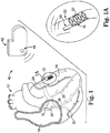
FIG. 1 shows an exemplary transvenousfy implantable medical device (TIMD) accessing a patient's heart according to embodiments of the present invention. -
FIG. 1A is an enlarged view showing the TIMD ofFIG. 1 in greater detail. -
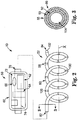
FIG. 2 is a schematic of the TIMD ofFIG. 1 . -
FIG. 3 shows a cross-section of a portion of a lead of the TIMD ofFIG. 1 . -
FIGS. 4-6 are illustrative of an exemplary method of transvenously implanting the TIMD ofFIG. 1 in a blood vessel according to embodiments of the present invention. -
FIGS. 7 and 8 show another exemplary TIMD according to embodiments of the present invention. -
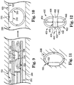
FIGS. 9 and 10 show another exemplary TIMD and method of transvenously implanting the TIMD according to embodiments of the present invention. -
FIG. 11 is illustrative of another method of transvenously implanting the TIMD ofFIGS. 9 and 10 according to embodiments of the present invention. -
FIG. 12 shows another exemplary TIMD according to embodiments of the present invention. - While the invention is amenable to various modifications and alternative forms, specific embodiments have been shown by way of example in the drawings and are described in detail below. The intention, however, is not to limit the invention to the particular embodiments described. On the contrary, the invention is intended to cover all modifications, equivalents, and alternatives falling within the scope of the invention as defined by the appended claims.
-
FIGS. 1 and 1A show a transvenously implantable medical device (TIMD) 10 according to embodiments of the present invention, whereFIG. 1A is an enlarged view showing theTIMD 10 in greater detail. The TIMD 10 is adapted to be implanted transvenously at a desired location within the vasculature of the patient. In some embodiments, the TIMD 10 is implanted within vasculature of theheart 12 to provide cardiac sensing and/or stimulation functionality. For example, the TIMD 10 can be used to sense various physiological characteristics of theheart 12 and/or to transmit a stimulating pulse of energy to tissue of theheart 12, such as the tissue forming theleft ventricle 14. - In some embodiments, the TIMD 10 is adapted to be implanted into the
right atrium 16, through thecoronary sinus ostium 18 and into thecoronary sinus 20 of theheart 12. As is subsequently described, catheter-based implantation is contemplated in association with theTIMD 10. The TIMD 10 is implantable within the left marginal vein 22 (as shown), or any other branch vein of thecoronary sinus 20, including any of those known in the art of cardiac management. For example, the TIMD 10 is optionally implanted within the greatcardiac vein 24, the middlecardiac vein 26, the left posteriorventricular vein 28, the smallcardiac vein 30, or others. - Although the TIMD 10 is implanted in vasculature of the
heart 12 in some embodiments, the TIMD 10 can also be implanted at other intravenous locations and/or to perform other functions. For example, the TIMD 10 is optionally implanted in vasculature of the neck, such as one of the jugular veins. The TIMD 10 can perform various functions from the jugular veins, such as cardiac rhythm management via vagal nerve stimulation, for example. As another example, the TIMD 10 is optionally implanted in peripheral vasculature and is adapted for acquiring diagnostic information, blood pressure for example, and then storing the diagnostic information, transmitting the diagnostic information to another implanted medical device (IMD), and/or transmitting the diagnostic information to an external device. - In some embodiments, the TIMD 10 is usable with a
wireless electrode system 40 that includes acontrol system 42 having atransmitter 44 for communicating with one or more wireless electrodes, such as the TIMD 10. In one embodiment, thetransmitter 44 is an inductive coil used to inductively charge the TIMD 10 with power and/or trigger delivery of stimulating energy from the TIMD 10 to theheart 12. In other embodiments, thetransmitter 44 is a radiofrequency communication device, an acoustic communication device, or other device for communicating with the TIMD 10. - In some embodiments, the
control system 42 directly controls stimulation via the TIMD 10 from outside of the body (externally, for example worn about the neck) or from within the body (internally, for example implanted similarly to a conventional pacemaker) using inductive communication/power transmission. Thecontrol system 42 can also use other types of communication to directly control stimulation or sensing functionality administered with the TIMD 10 in addition to or as an alternative to inductive transmission. For example, radiofrequency, optical, or acoustic communication between the TIMD 10 and thecontrol system 42 are also contemplated. Examples of various wireless electrode systems usable in association with the TIMD 10 are described inU.S. Patent App. Pub. 2006/0085039 , "Leadless Cardiac Stimulation Systems," andU.S. Patent App. Pub. 2003/0158584 , "Chronically-Implanted Device for Sensing and Therapy," the entire contents of each of which are incorporated herein by reference. - In some embodiments, the
control system 42 and the TIMD 10 are optionally deployed in a satellite-planet configuration, where thecontrol system 42 acts as a planet device and the TIMD 10, or a plurality of devices similar to the TIMD 10, act as one or more satellite device(s). The TIMD 10 andcontrol system 42 can have varying degrees of control over sensing/stimulating operation of the TIMD 10. In some embodiments, the TIMD 10 is programmed to manage cardiac stimulation for a substantial period of time. Examples of wireless, implanted electrodes that are programmable to control stimulating or sensing functionality, as well as examples of satellite-planet device configurations are described in previously-incorporatedU.S. Patent App. Pub. 2003/0158584 . -
FIG. 2 is a schematic view of the TIMD 10 in an unassembled state. The TIMD 10 includes acontrol module 50 and anelectrical lead 52 providing means for fixating thecontrol module 50 within vasculature. Thecontrol module 50 includes ahousing 60 and various electrical components, including asignal management component 62, apower component 64, and a communication component 66. Various components of thecontrol module 50, includingcomponents - The
housing 60 is adapted for transvenous delivery and implantation in human vasculature, including vasculature associated with theheart 12. Thehousing 60 is formed of metallic, polymeric, or other biocompatible materials. In one embodiment, thehousing 60 is substantially oblong and forms aterminal connector 70 adapted to be secured to thelead 52, a hermetically sealedinterior compartment 72 adapted to house and protect thecomponents housing 60. Theinner lumen 74 is generally adapted to facilitate implantation of theTIMD 10, as described subsequently in greater detail. In some embodiments, thehousing 60 includes drug delivery features, e.g., a steroid collar, drug eluting coating, or other therapeutic agents, or others. Thehousing 60 also optionally includes stimulating and/or sensing features, e.g., one or more electrodes associated with thehousing 60. - The
signal management component 62 includes circuitry for managing operation of theTIMD 10. In some embodiments, thesignal management component 62 controls delivery of stimulating energy from theTIMD 10. Thesignal management component 62 is optionally adapted to be programmed to execute various stimulation or sensing programs. In other embodiments, thesignal management component 62 is a hardwired circuit configured to deliver set stimulation or sensing programs upon initiation by a remote controller, such as the control system 42 (FIG. 1 ). - The
power component 64 operates to provide power to thesignal management component 62 and/or the communication component 66. In various embodiments, thepower component 64 is a battery, a coil for receiving a charge through inductance, or other type of power source for providing energy to theTIMD 10. In some embodiments, power is transmitted to thecontrol module 50 from an outside source, including those internal or external to the body, such as the control system 42 (FIG. 1 ). If desired, thepower component 64 is optionally integrated with the communication component 66 and data being transmitted to and received by thecontrol module 50 is encoded into the power transmission as a modulation of the power signal from thecontrol system 42. Examples of integrated power/communication arrangements are described in previously incorporatedU.S. Patent App. Pub. 2003/0158584 . - The communication component 66 serves to provide a communication link between the
TIMD 10 and one or more other devices, such as the control system 42 (FIG. 1 ), that are internal and/or external to the patient. The communication component 66 includes circuitry and/or other structures for providing communication between the chronically-implanted device and another device using radio-frequency (RF) waves, acoustics, or inductance, for example. In some embodiments, the communication component 66 includes an acoustic transmitter for transmitting an acoustic signal to another device, such as thecontrol system 42. For example, thecontrol system 42 is optionally an implanted cardiac stimulus device, such as a pacemaker and the communication component 66 is adapted to provide bidirectional communication between theTIMD 10 and thecontrol system 42. - The
lead 52 defines a central longitudinal axis X and includes alead body 80 extending from aterminal connector end 82 to adistal end 84.FIG. 3 shows a cross-section of a portion of thelead 52 along the line 3-3 shown inFIG. 2 . As shown inFIGS. 2 and 3 , thelead body 80 includes an outer, insulatingsheath 88, an inner,conductive core 90, an inner, insulatingsheath 92, and one ormore electrodes 98. Theelectrodes 98 include a plurality ofring electrodes 100 disposed circumferentially about thelead body 80 and atip electrode 102 located at thedistal end 84. - The
conductive core 90 is sandwiched between the outer and inner insulatingsheaths inner sheath 92 defines alumen 104 that is open at theterminal connector end 82. As shown, theelectrodes 98 are positioned along thelead body 80. Theelectrodes 98 are in electrical communication with theconductive core 90, providing an electrical pathway between theelectrodes 98 and thecontrol module 50. In some embodiments, thecore 90 is a coiled core, although other configurations are contemplated. For example, in other embodiments, thecore 90 is a cable or ribbon conductor. Theconductive core 90 can be made of any electrically conductive materials. - In some embodiments, the
lead 52 includes no lumens or greater number oflumens 104, a non-coiledconductive core 90, or other features associated with electrical leads. For example, in some embodiments, a steroid collar is employed with thelead 52 to help ensure proper pacing and/or as a therapeutic agent, including anti-inflammatories, antithrombogenics, antiproliferatives, or other types of therapeutic agents. Examples of various electrical lead features contemplated for use with thelead 52 are described inU.S. Patent No. 6,584,362 , "Leads for Pacing and/or Sensing the Heart from within the Coronary Veins," the entire contents of which are incorporated herein by reference. - The
electrodes 98 can be substantially the same as known electrodes for pacing and/or defibrillation leads. Theelectrodes 98 are formed of an electrically conductive material such as an alloy of platinum and iridium which is highly conductive and highly resistant to corrosion. In operation, theconductive core 90 carries electrical current between thecontrol module 50 and theelectrodes 98. As shown, thelead 52 is unipolar with a single conductor. In other embodiments, thelead 52 is bipolar where one or more of theelectrodes 98 are each in electrical communication with a plurality of separate conductors (not shown). - The
lead 52 is pre-biased to define a first shape in an expanded state (FIG. 2 ) and can be transitioned, or collapsed, to define a second shape in a collapsed state (FIG. 4 ). As shown inFIG. 2 andFIG. 4 , thelead 52 has a substantially larger maximum outer dimension in the expanded state than in the collapsed state. In different terms, thelead 52 defines a larger profile relative to the central longitudinal axis X of thelead 52 when the lead is in the expanded state in comparison to when thelead 52 is in the collapsed state. - As shown in
FIG. 2 , in the expanded state, thelead 52 naturally extends though an arcuate path to define a substantially helical, or coiled shape. As will be described in greater detail, other expanded state shapes are also contemplated, including generally arcuate shapes, undulating shapes, sinusoidal shapes, circular shapes, and others. Thelead 52 is pre-formed, or otherwise pre-biased to the shape exhibited in the expanded state via heat-setting, materials selection, plastic deformation of theconductive core 90, or using another technique known in the art. - As shown in
FIG. 4 , thelead 52 is straighter, or more linear, in the collapsed state than in the expanded state according to some embodiments. Various collapsed state shapes are contemplated, including helical shapes having a smaller transverse profile than in the expanded state. - One manner of assembling the
control module 50 to thelead 52 is described with reference toFIGS. 2, 3 , and4 . In particular, thecontrol module 50 is assembled to thelead 52 by securing theterminal connector end 82 of thelead 52 to theterminal connector 70 of thecontrol module 50. Upon assembly, the conductive core 90 (FIG. 3 ) of thelead 52 is placed in electrical communication with the components of thecontrol module 50 such that the signal management component 62 (FIG. 2 ) of themodule 50 can send a stimulation signal to, or receive a sensing signal from, theelectrodes 98 through theconductive core 90 of thelead 52. Additionally, the inner lumen 104 (FIG. 3 ) of thelead 52 is coaxially aligned to the inner lumen 74 (FIG. 2 ) of thecontrol module 50 to form a longitudinal passageway through thecontrol module 50 into thelead 52. In one embodiment, thelead 52 has specific biases to facilitate placement and retention of thelead 52 in the coronary sinus 20 (FIG. 1 ) or a branch vessel thereof. -
FIGS. 4-6 are illustrative of one embodiment method of transvenously implanting theTIMD 10 in ablood vessel 150 having avessel wall 152.FIG. 4 shows theTIMD 10 with thelead 52 in a collapsed state. In particular, a straighteningmember 160, such as a stylet or a guidewire having sufficient stiffness to straighten and maintain thelead 52 in the collapsed state, is inserted through theinner lumen 74 of thecontrol module 50 into thelead 52 to collapse thelead 52. - The
TIMD 10 and straighteningmember 160 are delivered to a desired transvenous implantation site, for example in the coronary sinus 20 (FIG. 1 ) or a branch vein thereof. In some embodiments, theTIMD 10 and the straighteningmember 160 are delivered through aguide catheter 162 as shown inFIG. 4 . When theguide catheter 162 is used, theTIMD 10 is deployed from theguide catheter 162 once theTIMD 10 is delivered proximate a desired location within theblood vessel 150. In other embodiments, theTIMD 10 is delivered directly to the desired implantation site using the straighteningmember 160 and in the absence of theguide catheter 162 in a manner substantially similar to an over-the-wire lead delivery technique. - The straightening
member 160 is then removed from theTIMD 10. If desired, asecondary member 164 can be deployed over the straighteningmember 160 to press against theTIMD 10 to assist with deployment of theTIMD 10 from theguide catheter 162 and/or removal of the straighteningmember 160 from theTIMD 10. In some embodiments, thesecondary member 164 is catheter-like in construction and formed according to catheter-based manufacturing methods. - As the straightening
member 160 is removed, the lead 52 transitions from the collapsed state to the expanded state shown inFIGS. 5 and 6 to contact thevessel wall 152. Thelead 52 provides means for anchoring or fixating theTIMD 10 in theblood vessel 150. In particular, the maximum outer dimension of thelead 52, for example the transverse diameter defined by the helical shape of thelead 52, is selected such that thelead 52 will mechanically engage thevessel wall 152. The mechanical engagement between the lead 52 and thevessel wall 152 is used to place one or more of theelectrodes 98 in electrical communication with thevessel wall 152 and to anchor or otherwise fixate the TIMD 10 in position within theblood vessel 150. In various embodiments, thelead 52 includes coatings, e.g., fibrosis encouraging coatings, or surface features to enhance frictional engagement with thevessel wall 152. In other embodiments, thelead 52 includes anti-fibrosis coatings or treatments to discourage fibrosis and facilitate lead extraction. As shown inFIG. 6 , upon expansion theTIMD 10 defines acentral passage 168 through the expanded shape of theTIMD 10. In some embodiments, thecentral passage 168 facilitates blood flow past theTIMD 10. - Once disposed within the
blood vessel 150, theTIMD 10 is used for sensing or stimulation according to various embodiments. For example, theblood vessel 150 is optionally the coronary sinus 20 (FIG. 1 ) or one of the branch vessels thereof. Theelectrodes 98 of theTIMD 10 can then be used to transmit a pulse of stimulating energy through thevessel wall 152 to surrounding tissue of theheart 12. - According to some methods of transvenous implantation, the
TIMD 10 is re-collapsible following transvenous implantation to remove or reposition theTIMD 10. For example, thesecondary member 164 can be used to grip thecontrol module 50 following implantation of theTIMD 10. In some embodiments, a vacuum is applied through thesecondary member 164, which secures thecontrol module 50 to thesecondary member 164. Thecontrol module 50 optionally includes aproximal seal 170 that is able to be engaged by thesecondary member 164. In one embodiment, theproximal seal 170 facilitates coupling of thecontrol module 50 to thesecondary member 164 via application of negative pressure through thesecondary member 164 by forming a better seal between thecontrol module 50 and thesecondary member 164. - In other embodiments, the
secondary member 164 includes gripping elements (not shown), somewhat like jaws of a pliers, for gripping thecontrol module 50 or associated structures. In still other embodiments, thecontrol module 50 includes a wire loop (not shown) and thesecondary member 164 includes a hook (not shown) for grasping the loop. Other means for securing thecontrol module 50 relative to thesecondary member 164 are also contemplated, including detents, magnets, adhesives, male and female threads, and others. - Once the
secondary member 164 is secured to thecontrol module 50, the straighteningmember 160 is reinserted into thelumen 104 of thelead 52 through theinner lumen 74 of thecontrol module 50. As the straighteningmember 160 is reintroduced into thelead 52, the lead 52 transitions to the collapsed state, and out of mechanical engagement with thevessel wall 152. Once thelead 52 has been partially or fully collapsed, theTIMD 10 is able to be removed or repositioned as desired. -
FIGS. 7 and 8 show anotherTIMD 200 according to some embodiments of the invention. TheTIMD 200 includes acontrol module 210 and anelectrical lead 220 providing means for fixating thecontrol module 210 within vasculature. In some embodiments, thecontrol module 210 and thelead 220 include substantially similar components as thecontrol module 50 and thelead 52 of theTIMD 10. Thelead 220 extends through an arcuate path and is curved or biased, being adapted to expand from a collapsed state (not shown), for example substantially straight, to an expanded state, for example having the curvatures shown inFIGS. 7 and 8 . Similarly to theTIMD 10, thelead 220 of theTIMD 200 defines a substantially larger maximum outer dimension in the expanded state than in the collapsed state. - As shown in
FIG. 7 , the curvature of thelead 220 is primarily in two dimensions, or within a single plane. As shown inFIG. 8 , the curvature oflead 220 also includes a non-planar component, with a second bend or curve in a second plane. Thelead 220 is pre-formed, or otherwise pre-biased to the expanded state via heat-setting, materials selection, plastic deformation, or others. In some embodiments, thelead 220 is constructed and arranged for fixation in thecoronary sinus 20, and is pre-biased to facilitate placement and retention in thecoronary sinus 20, or a branch vessel thereof. Various examples of structures and methods for providing such pre-biased, curved shapes are described in co-pendingU.S. Patent App. Ser. No. 11/277,326, filed March 23, 2006 - In some embodiments, the
TIMD 200 is transvenously implanted in a similar manner to theTIMD 10, for example using the guide catheter 162 (FIG. 4 ), the secondary member 164 (FIG. 4 ), and/or the straightening member 160 (FIG. 4 ) as previously described. Once implanted, thelead 220 is transitioned from the collapsed state to the expanded state to contact the vessel wall 152 (FIG. 4 ). The maximum outer dimension of thelead 220, for example the outer diameter defined by the arcuate shape of thelead 52, is selected such that thelead 52 will mechanically engage thevessel wall 152 to anchor theTIMD 200 in theblood vessel 150. TheTIMD 200 can also be removed from theblood vessel 150 in a similar manner to that described in association with theTIMD 10 according to some embodiments. -
FIGS. 9 and 10 show anotherTIMD 300 according to some embodiments of the invention and are illustrative of one method of transvenously implanting theTIMD 300. TheTIMD 300 includes acontrol module 310 and anelectrical lead 320 providing means for fixating thecontrol module 310 within vasculature. Thelead 320 is adapted to transition between a collapsed state and an expanded state. In some embodiments, thecontrol module 310 and thelead 320 include substantially similar components as thecontrol module 50 and thelead 52 of theTIMD 10. Thecontrol module 310 optionally includes one ormore electrodes 315 for performing sensing and/or stimulating functions similar to those previously described. In some embodiments, theelectrode 315 is used in conjunction with one or more electrodes of thelead 320. - As shown in
FIGS. 9 and 10 , thecontrol module 310 has a proximal end 330 and distal end 332 and thelead 320 has afirst end 334 and asecond end 336. Thefirst end 334 of thelead 320 is secured to the proximal end 330 of thecontrol module 310 while thesecond end 336 of thelead 320 is secured to the distal end 332 of thecontrol module 310. Thelead 320 extends through an arcuate shape from the proximal end 330 to the distal end 332 of thecontrol module 310. -
FIG. 9 shows thelead 320 in the collapsed state, where thelead 320 has been pressed into a more compact, linear shape than in the expanded state (FIG. 10). FIG. 10 shows thelead 320 in the expanded state, where thelead 320 defines a greater height, or outer diameter in the expanded state than in the collapsed state. In different terms, in the expanded state thelead 320 has a substantially larger maximum outer dimension than in the collapsed state. Thelead 320 is pre-formed, or otherwise pre-biased to the shape exhibited in the expanded state via heat-setting, materials selection, plastic deformation to impart a curvature, or others. - One method of transvenously implanting the
TIMD 300 is also generally illustrated inFIGS. 9 and 10 . As shown inFIG. 9 , thelead 320 is maintained in the collapsed state within acatheter 350. Thecatheter 350 is guided to a desired position within theblood vessel 150. Once theTIMD 300 is positioned proximate to the desired position for implantation, apusher 352 is used to eject theTIMD 300 from thecatheter 350. Once the external force of thecatheter 350 is removed from theTIMD 300, theTIMD 300 transitions to the expanded state as shown inFIG. 10 to engage thevessel wall 152 and anchor theTIMD 300 in place. Although theTIMD 300 is shown oriented "sideways" within theblood vessel 150, other orientations are also contemplated. For example, theTIMD 300 is optionally transvenously implanted as shown inFIG. 11 , where theTIMD 300 is oriented substantially coaxially with theblood vessel 150. -
FIG. 12 shows anotherexemplary TIMD 400 according to embodiments of the present invention. TheTIMD 400 includes acontrol module 410, a firstelectrical lead 420, and a secondelectrical lead 422, the first andsecond leads control module 410 within vasculature. The first andsecond leads control module 410 and theleads control module 50 and thelead 52 of the TIMD 10 (FIG. 1 ). - As shown in
FIG. 12 , thecontrol module 410 has aproximal end 430 anddistal end 432. Thefirst lead 420 has afirst end 434 and asecond end 436. Thesecond lead 422 has afirst end 438 and asecond end 440. The first ends 434, 438 of theleads proximal end 430 of thecontrol module 410 while the second ends 436, 440 of theleads distal end 432 of thecontrol module 410. The first andsecond leads control module 410 to define a pair of semi-circular shapes. - The leads 420, 422 are transitionable between an expanded state and a more compact, collapsed state.
FIG. 12 shows theleads leads FIG. 12 . The leads 420, 422 are sufficiently flexible to be compressed to a collapsed state where theleads leads control module 410 in the collapsed state. As described in association with other embodiments, theleads - The
TIMD 400 can also include means for transitioning theTIMD 400 to the collapsed state. In some embodiments, theTIMD 400 includes afilament 450 that can be tensioned to collapse the first andsecond leads control module 410. Theflament 450 includes aloop 452 at theproximal end 430 of thecontrol module 410. Thefilament 450 extends from theloop 452 through thecontrol module 410 and splits into afirst leg 454 and asecond leg 456. Thefirst leg 454 is secured to thefirst lead 420 while thesecond leg 456 is secured to thesecond lead 422. In operation, theloop 452 is pulled, which in turn tensions the first andsecond legs leads - The
TIMD 400 is transvenously implanted in a similar manner as that described in association with theTIMD 300. For example, thecatheter 350 is optionally used to maintain theTIMD 400 in the collapsed state. Thepusher 352 is then optionally used to eject theTIMD 400 from thecatheter 350. Once the external force of thecatheter 350 is removed from theTIMD 400, theTIMD 400 transitions to the expanded state as shown inFIG. 12 to engage thevessel wall 152 and anchor theTIMD 400 in place. - In some embodiments, the
TIMD 400 is removed from the blood vessel 150 (FIG. 10 ) by fully or partially collapsing theleads control module 410 using thefilament 450. For example, a catheter or other device (not shown) having gripping jaws or a hook is used to pull thefilament 450 by hooking, or grasping theloop 452 and pulling on theloop 452. Upon tensioning thefilament 450, theTIMD 400 is transitioned to the collapsed state and is repositioned as desired or removed entirely from theblood vessel 150. The various TIMD embodiments previously described can also include a filament forming a loop similar to thefilament 450 andloop 452 to provide means for grasping and/or collapsing the TIMDs associated with those embodiments. - Various modifications and additions can be made to the exemplary embodiments discussed without departing from the scope of the present invention. For example, while the embodiments described above refer to particular features, the scope of this invention also includes embodiments having different combinations of features and embodiments that do not include all of the described features. Accordingly, the scope of the present invention is intended to embrace all such alternatives, modifications, and variations as fall within the scope of the claims, together with all equivalents thereof.
- The subject matter of the present application covers, in particular, the following aspects.
- 1. A transvenously implantable medical device (TIMD) comprising:
- an electrical lead including one or more electrodes and being adapted for transvenous implantation, the electrical lead pre-biased to expand from a collapsed state to an expanded state to mechanically engage an internal wall of a blood vessel; and
- a control module secured to and in electrical communication with the electrical lead, the control module including a signal management component and a power component disposed in a housing adapted for implantation into the blood vessel, the control module adapted for at least one of stimulating and sensing a physiologic response using the one or more electrodes of the electrical lead.
- 2. The device of aspect 1, wherein the control module is adapted for wireless communication.
- 3. The device of aspect 1, wherein the electrical lead and the control module are adapted for transvenous implantation using a catheter.
- 4. The device of aspect 1, wherein the control module is adapted for stimulating cardiac tissue.
- 5. The implantable medical device of aspect 1, further comprising:
- a second lead adapted to expand from a collapsed state to an expanded state to mechanically engage the internal wall of the blood vessel, the second lead including one or more electrodes, wherein the control module is in electrical communication with the second lead.
- 6. The device of aspect 1, wherein the electrical lead defines a first end and a second end, and further wherein the first and second ends are secured to the housing of the control module.
- 7. The device of aspect 1, wherein the electrical lead defines a substantially arcuate shape in the expanded state.
- 8. The device of aspect 7, wherein the electrical lead defines a substantially helical shape in the expanded state.
- 9. The device of aspect 7, wherein the electrical lead defines a substantially J-shape in the expanded state.
- 10. The device of aspect 7, wherein the electrical lead defines a substantially sinusoidal shape in the expanded state.
- 11. The device of aspect 1, wherein the electrical lead includes a plurality of spaced-apart electrodes.
- 12. A transvenously implantable medical device (TIMD) comprising:
- a control module comprising:
- a housing adapted for transvenous implantation;
- a power source disposed in the housing; and
- a circuitry disposed in the housing and operatively coupled to the power source; and
- means for fixating the control module within the blood vessel, the means for fixating including at least one electrode in electrical communication with the control module.
- a control module comprising:
- 13. A method of transvenously implanting a TIMD comprising:
- collapsing a first lead, the first lead including an elongate lead body secured to a control module and at least one electrode in electrical communication with the control module;
- transvenously implanting the control module and the first lead into a blood vessel; and
- causing the first lead to expand to engage an inner wall of the blood vessel such that the control module and the first lead are anchored in the blood vessel.
- 14. The method of aspect 13, further comprising:
- stimulating cardiac tissue by transmitting stimulating energy from the control module to the at least one electrode of the first lead.
- 15. The method of aspect 13, further comprising:
- collapsing the first lead by inserting a straightening member into the first lead.
- 16. The method of aspect 13, wherein the first lead and the control module are implanted in a vein of a coronary sinus.
- 17. The method of aspect 13, wherein a second lead is secured to the control module, the method further comprising:
- expanding the second lead to mechanically engage an inner wall of the blood vessel such that the control module and the second lead are anchored in the blood vessel.
- 18. The method of aspect 13, wherein expanding the first lead includes causing the first lead to extend in a substantially arcuate shape.
- 19. The method of aspect 13, wherein expanding the first lead includes causing the first lead to extend in a substantially sinusoidal shape.
- 20. The method of aspect 13, wherein expanding the first lead includes causing the first lead to extend in a substantially helical shape.
Claims (15)
- A transvenously implantable medical device (10; 200; 300; 400) comprising:an electrical lead (52; 220; 320; 420, 422) including one or more electrodes (98, 100, 102; 315);a control module (50; 210; 310; 410) mechanically secured to and in electrical communication with the electrical lead, the control module including a signal management component (62) and a power component (64) disposed in a hermetically sealed housing (60) adapted for implantation into a blood vessel such that blood in the blood vessel can flow past the control module between the housing (60) and an internal wall of the blood vessel, the control module adapted for at least one of stimulating and sensing a physiologic response using the one or more electrodes of the electrical lead; andwherein the electrical lead further includes a lumen (104) extending therethrough configured to accommodate a straightening member within the lumen in order to adapt the electrical lead for transvenous implantation, the electrical lead is pre-biased to expand from a collapsed state to an expanded state to mechanically engage the internal wall of the blood vessel upon removal of the straightening member so as to anchor the electrical lead and the mechanically connected control module in the blood vessel.
- The device of claim 1, wherein the control module is adapted for wireless communication.
- The device of claim 1, wherein the electrical lead and the control module are adapted for transvenous implantation using a catheter.
- The device of claim 1, wherein the control module is adapted for stimulating cardiac tissue.
- The device of claim 1, further comprising:a second lead (422) adapted to expand from a collapsed state to an expanded state to mechanically engage the internal wall of the blood vessel, the second lead including one or more electrodes, wherein the control module is in electrical communication with the second lead.
- The device of claim 1, wherein the electrical lead defines a substantially arcuate shape in the expanded state.
- The device of claim 6, wherein the electrical lead defines a substantially helical shape in the expanded state.
- The device of claim 6, wherein the electrical lead defines a substantially J-shape in the expanded state.
- The device of claim 6, wherein the electrical lead defines a substantially sinusoidal shape in the expanded state.
- The device of claim 1, wherein the electrical lead includes a plurality of spaced-apart electrodes.
- The device of claim 10, wherein the electrical lead includes a plurality of conductors, wherein a first one of the plurality of spaced-apart electrodes is in electrical communication with a first of the plurality of conductors and a second one of the plurality of spaced-apart electrodes is in electrical communication with a second of the plurality of conductors.
- The device of claim 1, wherein the electrical lead includes an outer insulating sheath and an inner insulating sheath, wherein the inner insulating sheath defines at least part of the lumen (104).
- The device of claim 1, wherein the housing (60) includes a terminal connector (70) adapted to be secured to the electrical lead.
- The device of claim 1, wherein the control module includes a control module electrode, and the control module is adapted for at least one of stimulating and sensing a physiologic response using the control module electrode.
- The device of claim 1, wherein the control module further comprises an inductive coil to inductively re-charge the power component.
Applications Claiming Priority (3)
| Application Number | Priority Date | Filing Date | Title |
|---|---|---|---|
| US11/750,185 US8103359B2 (en) | 2007-05-17 | 2007-05-17 | Systems and methods for fixating transvenously implanted medical devices |
| EP08755404.4A EP2146776B1 (en) | 2007-05-17 | 2008-05-13 | Systems for fixating transvenously implanted medical devices |
| PCT/US2008/063542 WO2008144319A1 (en) | 2007-05-17 | 2008-05-13 | Systems and methods for fixating transvenously implanted medical devices |
Related Parent Applications (2)
| Application Number | Title | Priority Date | Filing Date |
|---|---|---|---|
| EP08755404.4A Division EP2146776B1 (en) | 2007-05-17 | 2008-05-13 | Systems for fixating transvenously implanted medical devices |
| EP08755404.4A Division-Into EP2146776B1 (en) | 2007-05-17 | 2008-05-13 | Systems for fixating transvenously implanted medical devices |
Publications (2)
| Publication Number | Publication Date |
|---|---|
| EP3300767A1 true EP3300767A1 (en) | 2018-04-04 |
| EP3300767B1 EP3300767B1 (en) | 2025-03-05 |
Family
ID=39666116
Family Applications (2)
| Application Number | Title | Priority Date | Filing Date |
|---|---|---|---|
| EP17193891.3A Active EP3300767B1 (en) | 2007-05-17 | 2008-05-13 | Systems for fixating transvenously implanted medical devices |
| EP08755404.4A Not-in-force EP2146776B1 (en) | 2007-05-17 | 2008-05-13 | Systems for fixating transvenously implanted medical devices |
Family Applications After (1)
| Application Number | Title | Priority Date | Filing Date |
|---|---|---|---|
| EP08755404.4A Not-in-force EP2146776B1 (en) | 2007-05-17 | 2008-05-13 | Systems for fixating transvenously implanted medical devices |
Country Status (4)
| Country | Link |
|---|---|
| US (4) | US8103359B2 (en) |
| EP (2) | EP3300767B1 (en) |
| JP (1) | JP5265670B2 (en) |
| WO (1) | WO2008144319A1 (en) |
Families Citing this family (147)
| Publication number | Priority date | Publication date | Assignee | Title |
|---|---|---|---|---|
| US6702811B2 (en) | 1999-04-05 | 2004-03-09 | Medtronic, Inc. | Ablation catheter assembly with radially decreasing helix and method of use |
| US20140018880A1 (en) | 2002-04-08 | 2014-01-16 | Medtronic Ardian Luxembourg S.A.R.L. | Methods for monopolar renal neuromodulation |
| US7653438B2 (en) | 2002-04-08 | 2010-01-26 | Ardian, Inc. | Methods and apparatus for renal neuromodulation |
| US8774913B2 (en) | 2002-04-08 | 2014-07-08 | Medtronic Ardian Luxembourg S.A.R.L. | Methods and apparatus for intravasculary-induced neuromodulation |
| US7532933B2 (en) | 2004-10-20 | 2009-05-12 | Boston Scientific Scimed, Inc. | Leadless cardiac stimulation systems |
| US7848823B2 (en) | 2005-12-09 | 2010-12-07 | Boston Scientific Scimed, Inc. | Cardiac stimulation system |
| US7840281B2 (en) | 2006-07-21 | 2010-11-23 | Boston Scientific Scimed, Inc. | Delivery of cardiac stimulation devices |
| WO2008034005A2 (en) | 2006-09-13 | 2008-03-20 | Boston Scientific Scimed, Inc. | Cardiac stimulation using leadless electrode assemblies |
| US8103359B2 (en) * | 2007-05-17 | 2012-01-24 | Cardiac Pacemakers, Inc. | Systems and methods for fixating transvenously implanted medical devices |
| US8738147B2 (en) | 2008-02-07 | 2014-05-27 | Cardiac Pacemakers, Inc. | Wireless tissue electrostimulation |
| US9468755B2 (en) | 2009-09-30 | 2016-10-18 | Respicardia, Inc. | Medical lead with preformed bias |
| WO2011072286A1 (en) * | 2009-12-11 | 2011-06-16 | Keith Leonard March | Implantable biomedical device leads comprising liquid conductors |
| JP2013544133A (en) | 2010-10-25 | 2013-12-12 | メドトロニック アーディアン ルクセンブルク ソシエテ ア レスポンサビリテ リミテ | Catheter apparatus having a multi-electrode array for renal neuromodulation and related systems and methods |
| US8489205B2 (en) * | 2011-05-03 | 2013-07-16 | Biotronik Se & Co. Kg | System for temporary fixation of an implantable medical device |
| EP2559453B1 (en) * | 2011-08-18 | 2014-07-16 | Sorin CRM SAS | Lead implantable in the coronary vessels for multi-zone stimulation of a left heart chamber |
| GB2523466B (en) * | 2012-04-10 | 2016-12-14 | Gloucestershire Hospitals Nhs Found Trust | Apparatus for artifical cardiac stimulation |
| US8888773B2 (en) | 2012-05-11 | 2014-11-18 | Medtronic Ardian Luxembourg S.A.R.L. | Multi-electrode catheter assemblies for renal neuromodulation and associated systems and methods |
| US9095321B2 (en) | 2012-11-21 | 2015-08-04 | Medtronic Ardian Luxembourg S.A.R.L. | Cryotherapeutic devices having integral multi-helical balloons and methods of making the same |
| US9179974B2 (en) | 2013-03-15 | 2015-11-10 | Medtronic Ardian Luxembourg S.A.R.L. | Helical push wire electrode |
| EP2813263A1 (en) * | 2013-06-12 | 2014-12-17 | Achim Gutersohn | Pacemaker system with a holding device |
| US20150073515A1 (en) | 2013-09-09 | 2015-03-12 | Medtronic Ardian Luxembourg S.a.r.I. | Neuromodulation Catheter Devices and Systems Having Energy Delivering Thermocouple Assemblies and Associated Methods |
| GB2519302B (en) * | 2013-10-15 | 2016-04-20 | Gloucestershire Hospitals Nhs Foundation Trust | Apparatus for artificial cardiac stimulation and method of using the same |
| US20150196769A1 (en) | 2014-01-10 | 2015-07-16 | Cardiac Pacemakers, Inc. | Methods and systems for improved communication between medical devices |
| AU2015204701B2 (en) | 2014-01-10 | 2018-03-15 | Cardiac Pacemakers, Inc. | Systems and methods for detecting cardiac arrhythmias |
| US10736690B2 (en) | 2014-04-24 | 2020-08-11 | Medtronic Ardian Luxembourg S.A.R.L. | Neuromodulation catheters and associated systems and methods |
| US9492671B2 (en) | 2014-05-06 | 2016-11-15 | Medtronic, Inc. | Acoustically triggered therapy delivery |
| US9999774B2 (en) | 2014-05-06 | 2018-06-19 | Medtronic, Inc. | Optical trigger for therapy delivery |
| US9669224B2 (en) | 2014-05-06 | 2017-06-06 | Medtronic, Inc. | Triggered pacing system |
| US10674928B2 (en) | 2014-07-17 | 2020-06-09 | Medtronic, Inc. | Leadless pacing system including sensing extension |
| US9399140B2 (en) | 2014-07-25 | 2016-07-26 | Medtronic, Inc. | Atrial contraction detection by a ventricular leadless pacing device for atrio-synchronous ventricular pacing |
| US9526909B2 (en) | 2014-08-28 | 2016-12-27 | Cardiac Pacemakers, Inc. | Medical device with triggered blanking period |
| US9623234B2 (en) | 2014-11-11 | 2017-04-18 | Medtronic, Inc. | Leadless pacing device implantation |
| US9492668B2 (en) | 2014-11-11 | 2016-11-15 | Medtronic, Inc. | Mode switching by a ventricular leadless pacing device |
| US9492669B2 (en) | 2014-11-11 | 2016-11-15 | Medtronic, Inc. | Mode switching by a ventricular leadless pacing device |
| US9724519B2 (en) | 2014-11-11 | 2017-08-08 | Medtronic, Inc. | Ventricular leadless pacing device mode switching |
| US9289612B1 (en) | 2014-12-11 | 2016-03-22 | Medtronic Inc. | Coordination of ventricular pacing in a leadless pacing system |
| ES2713231T3 (en) | 2015-02-06 | 2019-05-20 | Cardiac Pacemakers Inc | Systems for the safe supply of electrical stimulation therapy |
| EP3253448B1 (en) * | 2015-02-06 | 2021-02-24 | Cardiac Pacemakers, Inc. | Systems for treating cardiac arrhythmias |
| EP3827877B1 (en) | 2015-02-06 | 2024-06-19 | Cardiac Pacemakers, Inc. | Systems for treating cardiac arrhythmias |
| WO2016130477A2 (en) | 2015-02-09 | 2016-08-18 | Cardiac Pacemakers, Inc. | Implantable medical device with radiopaque id tag |
| EP3265172B1 (en) | 2015-03-04 | 2018-12-19 | Cardiac Pacemakers, Inc. | Systems for treating cardiac arrhythmias |
| US10050700B2 (en) | 2015-03-18 | 2018-08-14 | Cardiac Pacemakers, Inc. | Communications in a medical device system with temporal optimization |
| CN107427222B (en) | 2015-03-18 | 2021-02-09 | 心脏起搏器股份公司 | Communication in a medical device system using link quality assessment |
| WO2017031347A1 (en) | 2015-08-20 | 2017-02-23 | Cardiac Pacemakers, Inc. | Systems and methods for communication between medical devices |
| US9853743B2 (en) | 2015-08-20 | 2017-12-26 | Cardiac Pacemakers, Inc. | Systems and methods for communication between medical devices |
| US9968787B2 (en) | 2015-08-27 | 2018-05-15 | Cardiac Pacemakers, Inc. | Spatial configuration of a motion sensor in an implantable medical device |
| US9956414B2 (en) | 2015-08-27 | 2018-05-01 | Cardiac Pacemakers, Inc. | Temporal configuration of a motion sensor in an implantable medical device |
| WO2017040115A1 (en) | 2015-08-28 | 2017-03-09 | Cardiac Pacemakers, Inc. | System for detecting tamponade |
| US10226631B2 (en) | 2015-08-28 | 2019-03-12 | Cardiac Pacemakers, Inc. | Systems and methods for infarct detection |
| US10137305B2 (en) | 2015-08-28 | 2018-11-27 | Cardiac Pacemakers, Inc. | Systems and methods for behaviorally responsive signal detection and therapy delivery |
| WO2017044389A1 (en) | 2015-09-11 | 2017-03-16 | Cardiac Pacemakers, Inc. | Arrhythmia detection and confirmation |
| US10065041B2 (en) | 2015-10-08 | 2018-09-04 | Cardiac Pacemakers, Inc. | Devices and methods for adjusting pacing rates in an implantable medical device |
| JP6608063B2 (en) | 2015-12-17 | 2019-11-20 | カーディアック ペースメイカーズ, インコーポレイテッド | Implantable medical device |
| US10905886B2 (en) | 2015-12-28 | 2021-02-02 | Cardiac Pacemakers, Inc. | Implantable medical device for deployment across the atrioventricular septum |
| WO2017127548A1 (en) | 2016-01-19 | 2017-07-27 | Cardiac Pacemakers, Inc. | Devices for wirelessly recharging a rechargeable battery of an implantable medical device |
| WO2017136548A1 (en) | 2016-02-04 | 2017-08-10 | Cardiac Pacemakers, Inc. | Delivery system with force sensor for leadless cardiac device |
| US11116988B2 (en) | 2016-03-31 | 2021-09-14 | Cardiac Pacemakers, Inc. | Implantable medical device with rechargeable battery |
| US10328272B2 (en) | 2016-05-10 | 2019-06-25 | Cardiac Pacemakers, Inc. | Retrievability for implantable medical devices |
| US10668294B2 (en) | 2016-05-10 | 2020-06-02 | Cardiac Pacemakers, Inc. | Leadless cardiac pacemaker configured for over the wire delivery |
| JP6764956B2 (en) | 2016-06-27 | 2020-10-07 | カーディアック ペースメイカーズ, インコーポレイテッド | Cardiac therapy system that uses subcutaneously sensed P-waves for resynchronization pacing management |
| US11207527B2 (en) | 2016-07-06 | 2021-12-28 | Cardiac Pacemakers, Inc. | Method and system for determining an atrial contraction timing fiducial in a leadless cardiac pacemaker system |
| WO2018009392A1 (en) | 2016-07-07 | 2018-01-11 | Cardiac Pacemakers, Inc. | Leadless pacemaker using pressure measurements for pacing capture verification |
| CN109475743B (en) | 2016-07-20 | 2022-09-02 | 心脏起搏器股份公司 | System for utilizing atrial contraction timing references in a leadless cardiac pacemaker system |
| WO2018035343A1 (en) | 2016-08-19 | 2018-02-22 | Cardiac Pacemakers, Inc. | Trans septal implantable medical device |
| EP3503970B1 (en) | 2016-08-24 | 2023-01-04 | Cardiac Pacemakers, Inc. | Cardiac resynchronization using fusion promotion for timing management |
| CN109640809B (en) | 2016-08-24 | 2021-08-17 | 心脏起搏器股份公司 | Integrated multi-device cardiac resynchronization therapy using P-wave to pacing timing |
| WO2018057318A1 (en) | 2016-09-21 | 2018-03-29 | Cardiac Pacemakers, Inc. | Leadless stimulation device with a housing that houses internal components of the leadless stimulation device and functions as the battery case and a terminal of an internal battery |
| WO2018057626A1 (en) | 2016-09-21 | 2018-03-29 | Cardiac Pacemakers, Inc. | Implantable cardiac monitor |
| US10758737B2 (en) | 2016-09-21 | 2020-09-01 | Cardiac Pacemakers, Inc. | Using sensor data from an intracardially implanted medical device to influence operation of an extracardially implantable cardioverter |
| US10413733B2 (en) | 2016-10-27 | 2019-09-17 | Cardiac Pacemakers, Inc. | Implantable medical device with gyroscope |
| WO2018081275A1 (en) | 2016-10-27 | 2018-05-03 | Cardiac Pacemakers, Inc. | Multi-device cardiac resynchronization therapy with timing enhancements |
| AU2017350759B2 (en) | 2016-10-27 | 2019-10-17 | Cardiac Pacemakers, Inc. | Implantable medical device with pressure sensor |
| WO2018081133A1 (en) | 2016-10-27 | 2018-05-03 | Cardiac Pacemakers, Inc. | Implantable medical device having a sense channel with performance adjustment |
| US10758724B2 (en) | 2016-10-27 | 2020-09-01 | Cardiac Pacemakers, Inc. | Implantable medical device delivery system with integrated sensor |
| WO2018081237A1 (en) | 2016-10-27 | 2018-05-03 | Cardiac Pacemakers, Inc. | Use of a separate device in managing the pace pulse energy of a cardiac pacemaker |
| US10434317B2 (en) | 2016-10-31 | 2019-10-08 | Cardiac Pacemakers, Inc. | Systems and methods for activity level pacing |
| EP3532157B1 (en) | 2016-10-31 | 2020-08-26 | Cardiac Pacemakers, Inc. | Systems for activity level pacing |
| WO2018089311A1 (en) | 2016-11-08 | 2018-05-17 | Cardiac Pacemakers, Inc | Implantable medical device for atrial deployment |
| WO2018089308A1 (en) | 2016-11-09 | 2018-05-17 | Cardiac Pacemakers, Inc. | Systems, devices, and methods for setting cardiac pacing pulse parameters for a cardiac pacing device |
| EP3541472B1 (en) | 2016-11-21 | 2023-06-07 | Cardiac Pacemakers, Inc. | Implantable medical device with a magnetically permeable housing and an inductive coil disposed about the housing |
| US10881869B2 (en) | 2016-11-21 | 2021-01-05 | Cardiac Pacemakers, Inc. | Wireless re-charge of an implantable medical device |
| CN109982746B (en) | 2016-11-21 | 2023-04-04 | 心脏起搏器股份公司 | Leadless cardiac pacemaker providing cardiac resynchronization therapy |
| US10639486B2 (en) | 2016-11-21 | 2020-05-05 | Cardiac Pacemakers, Inc. | Implantable medical device with recharge coil |
| EP3541473B1 (en) | 2016-11-21 | 2020-11-11 | Cardiac Pacemakers, Inc. | Leadless cardiac pacemaker with multimode communication |
| US10675476B2 (en) | 2016-12-22 | 2020-06-09 | Cardiac Pacemakers, Inc. | Internal thoracic vein placement of a transmitter electrode for leadless stimulation of the heart |
| US11207532B2 (en) | 2017-01-04 | 2021-12-28 | Cardiac Pacemakers, Inc. | Dynamic sensing updates using postural input in a multiple device cardiac rhythm management system |
| JP7000438B2 (en) | 2017-01-26 | 2022-01-19 | カーディアック ペースメイカーズ, インコーポレイテッド | Human device communication with redundant message transmission |
| CN110198759B (en) | 2017-01-26 | 2023-08-11 | 心脏起搏器股份公司 | Leadless implantable device with removable fasteners |
| CN110234392B (en) | 2017-01-26 | 2023-08-11 | 心脏起搏器股份公司 | Leadless device with overmolded components |
| US11160989B2 (en) | 2017-03-20 | 2021-11-02 | Cardiac Pacemakers, Inc. | Systems and methods for treating cardiac arrhythmias |
| US10994148B2 (en) | 2017-03-20 | 2021-05-04 | Cardiac Pacemakers, Inc. | Systems and methods for treating cardiac arrhythmias |
| JP6888112B2 (en) * | 2017-03-20 | 2021-06-16 | カーディアック ペースメイカーズ, インコーポレイテッド | Leadless pacing device for treating cardiac arrhythmias |
| CN110430920B (en) | 2017-03-20 | 2023-10-27 | 心脏起搏器股份公司 | Leadless pacing devices for the treatment of cardiac arrhythmias |
| US10821288B2 (en) | 2017-04-03 | 2020-11-03 | Cardiac Pacemakers, Inc. | Cardiac pacemaker with pacing pulse energy adjustment based on sensed heart rate |
| US10905872B2 (en) | 2017-04-03 | 2021-02-02 | Cardiac Pacemakers, Inc. | Implantable medical device with a movable electrode biased toward an extended position |
| US10849522B2 (en) | 2017-04-03 | 2020-12-01 | Cardiac Pacemakers, Inc. | Modular cardiac rhythm management using Q to LV activation measures |
| EP3668592B1 (en) | 2017-08-18 | 2021-11-17 | Cardiac Pacemakers, Inc. | Implantable medical device with pressure sensor |
| WO2019036568A1 (en) | 2017-08-18 | 2019-02-21 | Cardiac Pacemakers, Inc. | Implantable medical device with a flux concentrator and a receiving coil disposed about the flux concentrator |
| KR102670640B1 (en) * | 2017-08-26 | 2024-05-30 | 트랜스뮤럴 시스템스 엘엘씨 | Cardiac annuloplasty and pacing procedures, and related devices and methods |
| JP6938778B2 (en) | 2017-09-20 | 2021-09-22 | カーディアック ペースメイカーズ, インコーポレイテッド | Implantable medical device with multiple modes of operation |
| US11185703B2 (en) | 2017-11-07 | 2021-11-30 | Cardiac Pacemakers, Inc. | Leadless cardiac pacemaker for bundle of his pacing |
| EP3717063B1 (en) | 2017-12-01 | 2023-12-27 | Cardiac Pacemakers, Inc. | Systems for detecting atrial contraction timing fiducials and determining a cardiac interval from a ventricularly implanted leadless cardiac pacemaker |
| EP3717059B1 (en) | 2017-12-01 | 2024-11-20 | Cardiac Pacemakers, Inc. | Systems for detecting atrial contraction timing fiducials within a search window from a ventricularly implanted leadless cardiac pacemaker |
| EP3717060B1 (en) | 2017-12-01 | 2022-10-05 | Cardiac Pacemakers, Inc. | Leadless cardiac pacemaker with reversionary behavior |
| WO2019108545A1 (en) | 2017-12-01 | 2019-06-06 | Cardiac Pacemakers, Inc. | Methods and systems for detecting atrial contraction timing fiducials during ventricular filling from a ventricularly implanted leadless cardiac pacemaker |
| WO2019126295A1 (en) | 2017-12-22 | 2019-06-27 | Cardiac Pacemakers, Inc. | Implantable medical device for vascular deployment |
| WO2019126281A1 (en) | 2017-12-22 | 2019-06-27 | Cardiac Pacemakers, Inc. | Implantable medical device for vascular deployment |
| US11529523B2 (en) | 2018-01-04 | 2022-12-20 | Cardiac Pacemakers, Inc. | Handheld bridge device for providing a communication bridge between an implanted medical device and a smartphone |
| EP3735293B1 (en) | 2018-01-04 | 2022-03-09 | Cardiac Pacemakers, Inc. | Dual chamber pacing without beat-to-beat communication |
| US11058880B2 (en) | 2018-03-23 | 2021-07-13 | Medtronic, Inc. | VFA cardiac therapy for tachycardia |
| EP3768369A1 (en) | 2018-03-23 | 2021-01-27 | Medtronic, Inc. | Av synchronous vfa cardiac therapy |
| JP2021518192A (en) | 2018-03-23 | 2021-08-02 | メドトロニック,インコーポレイテッド | VfA cardiac resynchronization therapy |
| EP3549518A1 (en) | 2018-04-04 | 2019-10-09 | BIOTRONIK SE & Co. KG | Retaining structure for an implant |
| AU2019222842A1 (en) | 2018-09-10 | 2020-03-26 | Northern Development AS | Percutaneous Lead |
| EP3856331A1 (en) | 2018-09-26 | 2021-08-04 | Medtronic, Inc. | Capture in ventricle-from-atrium cardiac therapy |
| US11951313B2 (en) | 2018-11-17 | 2024-04-09 | Medtronic, Inc. | VFA delivery systems and methods |
| US12320769B2 (en) | 2018-11-19 | 2025-06-03 | The Regents Of The University Of California | Systems and methods for battery-less wirelessly powered dielectric sensors |
| WO2020106862A1 (en) | 2018-11-20 | 2020-05-28 | The Regents Of The University Of California | Systems and methods for controlling wirelessly powered leadless pacemakers |
| EP3897816B1 (en) | 2018-12-21 | 2024-03-27 | Medtronic, Inc. | Delivery systems for left ventricular pacing |
| EP3906085A4 (en) | 2019-01-04 | 2022-09-28 | Shifamed Holdings, LLC | INTERNAL CHARGING SYSTEMS AND METHODS OF USE |
| US11679265B2 (en) | 2019-02-14 | 2023-06-20 | Medtronic, Inc. | Lead-in-lead systems and methods for cardiac therapy |
| WO2020172478A1 (en) * | 2019-02-20 | 2020-08-27 | Ablation Innovations, LLC | Apparatus, systems, and methods to improve atrial fibrillation outcomes involving the left atrial appendage |
| WO2020205397A1 (en) | 2019-03-29 | 2020-10-08 | Cardiac Pacemakers, Inc. | Systems and methods for treating cardiac arrhythmias |
| US11697025B2 (en) | 2019-03-29 | 2023-07-11 | Medtronic, Inc. | Cardiac conduction system capture |
| CN113660977B (en) | 2019-03-29 | 2024-12-17 | 心脏起搏器股份公司 | Systems and methods for treating cardiac arrhythmias |
| US11213676B2 (en) | 2019-04-01 | 2022-01-04 | Medtronic, Inc. | Delivery systems for VfA cardiac therapy |
| US11712188B2 (en) | 2019-05-07 | 2023-08-01 | Medtronic, Inc. | Posterior left bundle branch engagement |
| US12052533B2 (en) | 2019-07-08 | 2024-07-30 | The Regents Of The University Of California | Systems and methods for long-distance remote sensing with sub-wavelength resolution using a wirelessly-powered sensor tag array |
| US11305127B2 (en) | 2019-08-26 | 2022-04-19 | Medtronic Inc. | VfA delivery and implant region detection |
| WO2021050589A1 (en) | 2019-09-09 | 2021-03-18 | Shifamed Holdings, Llc | Adjustable shunts and associated systems and methods |
| WO2021050685A1 (en) | 2019-09-11 | 2021-03-18 | Cardiac Pacemakers, Inc. | Tools and systems for implanting and/or retrieving a leadless cardiac pacing device with helix fixation |
| US11510697B2 (en) | 2019-09-11 | 2022-11-29 | Cardiac Pacemakers, Inc. | Tools and systems for implanting and/or retrieving a leadless cardiac pacing device with helix fixation |
| WO2021113670A1 (en) | 2019-12-05 | 2021-06-10 | Shifamed Holdings, Llc | Implantable shunt systems and methods |
| US11813466B2 (en) | 2020-01-27 | 2023-11-14 | Medtronic, Inc. | Atrioventricular nodal stimulation |
| JP2023515580A (en) | 2020-02-28 | 2023-04-13 | ザ リージェンツ オブ ザ ユニバーシティ オブ カリフォルニア | Integrated Energy Recovery Transceiver and Transmitter with Dual Antenna Architecture for Microimplants and Electrochemical Sensors |
| US12543992B2 (en) | 2020-03-30 | 2026-02-10 | Medtronic, Inc. | Pacing efficacy determination using a representative morphology of external cardiac signals |
| US11911168B2 (en) | 2020-04-03 | 2024-02-27 | Medtronic, Inc. | Cardiac conduction system therapy benefit determination |
| EP4138649B1 (en) | 2020-04-23 | 2025-09-24 | Shifamed Holdings, LLC | Intracardiac sensors with switchable configurations and associated systems and methods |
| EP4138981A4 (en) | 2020-04-23 | 2024-05-22 | Shifamed Holdings, LLC | Power management for interatrial shunts and associated systems and methods |
| US12605103B2 (en) | 2020-05-21 | 2026-04-21 | Medtronic, Inc. | QRS detection and bracketing |
| US12465770B2 (en) | 2020-07-31 | 2025-11-11 | Medtronic, Inc. | Coronary sinus conduction system pacing and delivery |
| US11813464B2 (en) | 2020-07-31 | 2023-11-14 | Medtronic, Inc. | Cardiac conduction system evaluation |
| US11801369B2 (en) | 2020-08-25 | 2023-10-31 | Shifamed Holdings, Llc | Adjustable interatrial shunts and associated systems and methods |
| US11857197B2 (en) | 2020-11-12 | 2024-01-02 | Shifamed Holdings, Llc | Adjustable implantable devices and associated methods |
| WO2022192280A1 (en) | 2021-03-09 | 2022-09-15 | Shifamed Holdings, Llc | Shape memory actuators for adjustable shunting systems, and associated systems and methods |
| CN117241751A (en) * | 2021-05-22 | 2023-12-15 | 斯奈普医疗有限公司 | Tumor ablation tools and techniques |
| EP4190398A1 (en) * | 2021-12-02 | 2023-06-07 | BIOTRONIK SE & Co. KG | Anchoring device for anchoring an implantable medical device on tissue |
Citations (7)
| Publication number | Priority date | Publication date | Assignee | Title |
|---|---|---|---|---|
| US20030050681A1 (en) * | 1998-11-20 | 2003-03-13 | Pianca Anne M. | Self-anchoring coronary sinus lead |
| US6584362B1 (en) | 2000-08-30 | 2003-06-24 | Cardiac Pacemakers, Inc. | Leads for pacing and/or sensing the heart from within the coronary veins |
| US20030158584A1 (en) | 2002-02-19 | 2003-08-21 | Cates Adam W | Chronically-implanted device for sensing and therapy |
| US20050154437A1 (en) * | 2003-12-12 | 2005-07-14 | Williams Michael S. | Implantable medical device having pre-implant exoskeleton |
| US20060085039A1 (en) | 2004-10-20 | 2006-04-20 | Hastings Roger N | Leadless cardiac stimulation systems |
| WO2006102290A2 (en) * | 2005-03-24 | 2006-09-28 | Synecor, L.L.C. | Flexible hermetic enclosure for implantable medical devices |
| US20060224225A1 (en) * | 2003-06-04 | 2006-10-05 | Terrance Ransbury | Implantable intravascular device for defibrillation and/or pacing |
Family Cites Families (28)
| Publication number | Priority date | Publication date | Assignee | Title |
|---|---|---|---|---|
| US4531933A (en) * | 1982-12-07 | 1985-07-30 | C. R. Bard, Inc. | Helical ureteral stent |
| US5000190A (en) * | 1988-06-22 | 1991-03-19 | The Cleveland Clinic Foundation | Continuous cardiac output by impedance measurements in the heart |
| US5387233A (en) * | 1993-01-11 | 1995-02-07 | Incontrol, Inc. | Intravenous cardiac lead with improved fixation and method |
| US5476498A (en) * | 1994-08-15 | 1995-12-19 | Incontrol, Inc. | Coronary sinus channel lead and method |
| NL9401690A (en) * | 1994-10-13 | 1996-05-01 | Industrial Res Bv | Body-implantable stent. |
| US5925073A (en) * | 1998-02-23 | 1999-07-20 | Cardiac Pacemakers, Inc. | Intravenous cardiac lead with wave shaped fixation segment |
| US6309350B1 (en) * | 1999-05-03 | 2001-10-30 | Tricardia, L.L.C. | Pressure/temperature/monitor device for heart implantation |
| US6654638B1 (en) * | 2000-04-06 | 2003-11-25 | Cardiac Pacemakers, Inc. | Ultrasonically activated electrodes |
| US6442413B1 (en) * | 2000-05-15 | 2002-08-27 | James H. Silver | Implantable sensor |
| US6445953B1 (en) * | 2001-01-16 | 2002-09-03 | Kenergy, Inc. | Wireless cardiac pacing system with vascular electrode-stents |
| US7519421B2 (en) * | 2001-01-16 | 2009-04-14 | Kenergy, Inc. | Vagal nerve stimulation using vascular implanted devices for treatment of atrial fibrillation |
| US20020116029A1 (en) * | 2001-02-20 | 2002-08-22 | Victor Miller | MRI-compatible pacemaker with power carrying photonic catheter and isolated pulse generating electronics providing VOO functionality |
| US20020116033A1 (en) * | 2001-02-20 | 2002-08-22 | Wilson Greatbatch | Controllable, wearable MRI-compatible cardiac pacemaker with pulse carrying photonic catheter and VOO functionality |
| US20030109901A1 (en) * | 2001-12-11 | 2003-06-12 | Wilson Greatbatch | Photonic pacemaker-cardiac monitor |
| US7653438B2 (en) * | 2002-04-08 | 2010-01-26 | Ardian, Inc. | Methods and apparatus for renal neuromodulation |
| US7203548B2 (en) * | 2002-06-20 | 2007-04-10 | Advanced Bionics Corporation | Cavernous nerve stimulation via unidirectional propagation of action potentials |
| US6882887B1 (en) * | 2002-12-16 | 2005-04-19 | Pacesetter, Inc. | Implantable lead and electrode portion |
| US7003350B2 (en) * | 2003-11-03 | 2006-02-21 | Kenergy, Inc. | Intravenous cardiac pacing system with wireless power supply |
| US20070106357A1 (en) * | 2005-11-04 | 2007-05-10 | Stephen Denker | Intravascular Electronics Carrier Electrode for a Transvascular Tissue Stimulation System |
| US7610092B2 (en) * | 2004-12-21 | 2009-10-27 | Ebr Systems, Inc. | Leadless tissue stimulation systems and methods |
| US20060064133A1 (en) * | 2004-09-17 | 2006-03-23 | Cardiac Pacemakers, Inc. | System and method for deriving relative physiologic measurements using an external computing device |
| CA2583404A1 (en) | 2004-10-20 | 2006-04-27 | Boston Scientific Limited | Leadless cardiac stimulation systems |
| US7647109B2 (en) * | 2004-10-20 | 2010-01-12 | Boston Scientific Scimed, Inc. | Leadless cardiac stimulation systems |
| US20060122522A1 (en) * | 2004-12-03 | 2006-06-08 | Abhi Chavan | Devices and methods for positioning and anchoring implantable sensor devices |
| US9155479B2 (en) * | 2005-12-12 | 2015-10-13 | Tor Peters | Intra cardiac device, system and methods |
| US7747334B2 (en) | 2006-03-23 | 2010-06-29 | Cardiac Pacemakers, Inc. | Left ventricular lead shapes |
| US7725197B2 (en) | 2006-06-15 | 2010-05-25 | Cardiac Pacemakers, Inc. | Medical electrical lead with friction-enhancing fixation features |
| US8103359B2 (en) * | 2007-05-17 | 2012-01-24 | Cardiac Pacemakers, Inc. | Systems and methods for fixating transvenously implanted medical devices |
-
2007
- 2007-05-17 US US11/750,185 patent/US8103359B2/en not_active Expired - Fee Related
-
2008
- 2008-05-13 EP EP17193891.3A patent/EP3300767B1/en active Active
- 2008-05-13 EP EP08755404.4A patent/EP2146776B1/en not_active Not-in-force
- 2008-05-13 JP JP2010508549A patent/JP5265670B2/en not_active Expired - Fee Related
- 2008-05-13 WO PCT/US2008/063542 patent/WO2008144319A1/en not_active Ceased
-
2011
- 2011-12-28 US US13/338,924 patent/US8798770B2/en active Active
-
2014
- 2014-07-21 US US14/336,308 patent/US9827426B2/en active Active
-
2016
- 2016-02-04 US US15/015,721 patent/US20160158561A1/en not_active Abandoned
Patent Citations (7)
| Publication number | Priority date | Publication date | Assignee | Title |
|---|---|---|---|---|
| US20030050681A1 (en) * | 1998-11-20 | 2003-03-13 | Pianca Anne M. | Self-anchoring coronary sinus lead |
| US6584362B1 (en) | 2000-08-30 | 2003-06-24 | Cardiac Pacemakers, Inc. | Leads for pacing and/or sensing the heart from within the coronary veins |
| US20030158584A1 (en) | 2002-02-19 | 2003-08-21 | Cates Adam W | Chronically-implanted device for sensing and therapy |
| US20060224225A1 (en) * | 2003-06-04 | 2006-10-05 | Terrance Ransbury | Implantable intravascular device for defibrillation and/or pacing |
| US20050154437A1 (en) * | 2003-12-12 | 2005-07-14 | Williams Michael S. | Implantable medical device having pre-implant exoskeleton |
| US20060085039A1 (en) | 2004-10-20 | 2006-04-20 | Hastings Roger N | Leadless cardiac stimulation systems |
| WO2006102290A2 (en) * | 2005-03-24 | 2006-09-28 | Synecor, L.L.C. | Flexible hermetic enclosure for implantable medical devices |
Also Published As
| Publication number | Publication date |
|---|---|
| US20080288039A1 (en) | 2008-11-20 |
| US20160158561A1 (en) | 2016-06-09 |
| US8798770B2 (en) | 2014-08-05 |
| EP3300767B1 (en) | 2025-03-05 |
| JP5265670B2 (en) | 2013-08-14 |
| EP2146776A1 (en) | 2010-01-27 |
| US20140336668A1 (en) | 2014-11-13 |
| US20120101553A1 (en) | 2012-04-26 |
| US8103359B2 (en) | 2012-01-24 |
| WO2008144319A1 (en) | 2008-11-27 |
| JP2010527267A (en) | 2010-08-12 |
| EP2146776B1 (en) | 2017-11-01 |
| US9827426B2 (en) | 2017-11-28 |
Similar Documents
| Publication | Publication Date | Title |
|---|---|---|
| EP3300767B1 (en) | Systems for fixating transvenously implanted medical devices | |
| US6697676B2 (en) | Medical electrical lead having an expandable electrode assembly | |
| US8676347B2 (en) | Braided lead with embedded fixation structures | |
| US5954761A (en) | Implantable endocardial lead assembly having a stent | |
| US7519424B2 (en) | Intravascular medical device | |
| EP2024013B1 (en) | Implantable medical lead assemblies with delivery tether | |
| US20100210923A1 (en) | Deployable sensor platform on the lead system of an implantable device | |
| US8494651B2 (en) | Implantable leads with a conductor coil having two or more sections | |
| US20090024196A1 (en) | Implantable electrode, insertion tool for use therewith, and insertion method | |
| JP2007505699A (en) | Fixing medical electrical leads | |
| US20070179550A1 (en) | Intravascular medical device | |
| US10518083B2 (en) | Lead with braided reinforcement | |
| EP1986732A1 (en) | Intravascular medical device | |
| CN112996556A (en) | Leaded electrical stimulation system | |
| EP2887992A1 (en) | Compound-shaped stylet for torque transmission | |
| US9775985B2 (en) | Braided lead with embedded fixation structures | |
| EP1971398B1 (en) | Intravascular medical device | |
| EP4056224A1 (en) | Active implantable medical device for sensing an electric signal of an organ of a human or animal patient |
Legal Events
| Date | Code | Title | Description |
|---|---|---|---|
| PUAI | Public reference made under article 153(3) epc to a published international application that has entered the european phase |
Free format text: ORIGINAL CODE: 0009012 |
|
| STAA | Information on the status of an ep patent application or granted ep patent |
Free format text: STATUS: THE APPLICATION HAS BEEN PUBLISHED |
|
| AC | Divisional application: reference to earlier application |
Ref document number: 2146776 Country of ref document: EP Kind code of ref document: P |
|
| AK | Designated contracting states |
Kind code of ref document: A1 Designated state(s): AT BE BG CH CY CZ DE DK EE ES FI FR GB GR HR HU IE IS IT LI LT LU LV MC MT NL NO PL PT RO SE SI SK TR |
|
| STAA | Information on the status of an ep patent application or granted ep patent |
Free format text: STATUS: REQUEST FOR EXAMINATION WAS MADE |
|
| 17P | Request for examination filed |
Effective date: 20181004 |
|
| RBV | Designated contracting states (corrected) |
Designated state(s): AT BE BG CH CY CZ DE DK EE ES FI FR GB GR HR HU IE IS IT LI LT LU LV MC MT NL NO PL PT RO SE SI SK TR |
|
| STAA | Information on the status of an ep patent application or granted ep patent |
Free format text: STATUS: EXAMINATION IS IN PROGRESS |
|
| 17Q | First examination report despatched |
Effective date: 20210705 |
|
| GRAP | Despatch of communication of intention to grant a patent |
Free format text: ORIGINAL CODE: EPIDOSNIGR1 |
|
| STAA | Information on the status of an ep patent application or granted ep patent |
Free format text: STATUS: GRANT OF PATENT IS INTENDED |
|
| INTG | Intention to grant announced |
Effective date: 20240619 |
|
| GRAJ | Information related to disapproval of communication of intention to grant by the applicant or resumption of examination proceedings by the epo deleted |
Free format text: ORIGINAL CODE: EPIDOSDIGR1 |
|
| STAA | Information on the status of an ep patent application or granted ep patent |
Free format text: STATUS: EXAMINATION IS IN PROGRESS |
|
| GRAP | Despatch of communication of intention to grant a patent |
Free format text: ORIGINAL CODE: EPIDOSNIGR1 |
|
| STAA | Information on the status of an ep patent application or granted ep patent |
Free format text: STATUS: GRANT OF PATENT IS INTENDED |
|
| INTC | Intention to grant announced (deleted) | ||
| INTG | Intention to grant announced |
Effective date: 20241010 |
|
| GRAS | Grant fee paid |
Free format text: ORIGINAL CODE: EPIDOSNIGR3 |
|
| GRAA | (expected) grant |
Free format text: ORIGINAL CODE: 0009210 |
|
| STAA | Information on the status of an ep patent application or granted ep patent |
Free format text: STATUS: THE PATENT HAS BEEN GRANTED |
|
| AC | Divisional application: reference to earlier application |
Ref document number: 2146776 Country of ref document: EP Kind code of ref document: P |
|
| AK | Designated contracting states |
Kind code of ref document: B1 Designated state(s): AT BE BG CH CY CZ DE DK EE ES FI FR GB GR HR HU IE IS IT LI LT LU LV MC MT NL NO PL PT RO SE SI SK TR |
|
| REG | Reference to a national code |
Ref country code: GB Ref legal event code: FG4D |
|
| REG | Reference to a national code |
Ref country code: CH Ref legal event code: EP |
|
| REG | Reference to a national code |
Ref country code: IE Ref legal event code: FG4D |
|
| REG | Reference to a national code |
Ref country code: DE Ref legal event code: R096 Ref document number: 602008065175 Country of ref document: DE |
|
| PG25 | Lapsed in a contracting state [announced via postgrant information from national office to epo] |
Ref country code: FI Free format text: LAPSE BECAUSE OF FAILURE TO SUBMIT A TRANSLATION OF THE DESCRIPTION OR TO PAY THE FEE WITHIN THE PRESCRIBED TIME-LIMIT Effective date: 20250305 |
|
| PGFP | Annual fee paid to national office [announced via postgrant information from national office to epo] |
Ref country code: DE Payment date: 20250423 Year of fee payment: 18 |
|
| REG | Reference to a national code |
Ref country code: NL Ref legal event code: MP Effective date: 20250305 |
|
| PG25 | Lapsed in a contracting state [announced via postgrant information from national office to epo] |
Ref country code: ES Free format text: LAPSE BECAUSE OF FAILURE TO SUBMIT A TRANSLATION OF THE DESCRIPTION OR TO PAY THE FEE WITHIN THE PRESCRIBED TIME-LIMIT Effective date: 20250305 |
|
| REG | Reference to a national code |
Ref country code: LT Ref legal event code: MG9D |
|
| PG25 | Lapsed in a contracting state [announced via postgrant information from national office to epo] |
Ref country code: NO Free format text: LAPSE BECAUSE OF FAILURE TO SUBMIT A TRANSLATION OF THE DESCRIPTION OR TO PAY THE FEE WITHIN THE PRESCRIBED TIME-LIMIT Effective date: 20250605 |
|
| PG25 | Lapsed in a contracting state [announced via postgrant information from national office to epo] |
Ref country code: HR Free format text: LAPSE BECAUSE OF FAILURE TO SUBMIT A TRANSLATION OF THE DESCRIPTION OR TO PAY THE FEE WITHIN THE PRESCRIBED TIME-LIMIT Effective date: 20250305 |
|
| PG25 | Lapsed in a contracting state [announced via postgrant information from national office to epo] |
Ref country code: LV Free format text: LAPSE BECAUSE OF FAILURE TO SUBMIT A TRANSLATION OF THE DESCRIPTION OR TO PAY THE FEE WITHIN THE PRESCRIBED TIME-LIMIT Effective date: 20250305 |
|
| PGFP | Annual fee paid to national office [announced via postgrant information from national office to epo] |
Ref country code: FR Payment date: 20250423 Year of fee payment: 18 |
|
| PG25 | Lapsed in a contracting state [announced via postgrant information from national office to epo] |
Ref country code: GR Free format text: LAPSE BECAUSE OF FAILURE TO SUBMIT A TRANSLATION OF THE DESCRIPTION OR TO PAY THE FEE WITHIN THE PRESCRIBED TIME-LIMIT Effective date: 20250606 Ref country code: BG Free format text: LAPSE BECAUSE OF FAILURE TO SUBMIT A TRANSLATION OF THE DESCRIPTION OR TO PAY THE FEE WITHIN THE PRESCRIBED TIME-LIMIT Effective date: 20250305 |
|
| REG | Reference to a national code |
Ref country code: AT Ref legal event code: MK05 Ref document number: 1772379 Country of ref document: AT Kind code of ref document: T Effective date: 20250305 |
|
| PG25 | Lapsed in a contracting state [announced via postgrant information from national office to epo] |
Ref country code: NL Free format text: LAPSE BECAUSE OF FAILURE TO SUBMIT A TRANSLATION OF THE DESCRIPTION OR TO PAY THE FEE WITHIN THE PRESCRIBED TIME-LIMIT Effective date: 20250305 |
|
| PG25 | Lapsed in a contracting state [announced via postgrant information from national office to epo] |
Ref country code: SE Free format text: LAPSE BECAUSE OF FAILURE TO SUBMIT A TRANSLATION OF THE DESCRIPTION OR TO PAY THE FEE WITHIN THE PRESCRIBED TIME-LIMIT Effective date: 20250305 |
|
| PG25 | Lapsed in a contracting state [announced via postgrant information from national office to epo] |
Ref country code: PT Free format text: LAPSE BECAUSE OF FAILURE TO SUBMIT A TRANSLATION OF THE DESCRIPTION OR TO PAY THE FEE WITHIN THE PRESCRIBED TIME-LIMIT Effective date: 20250707 |
|
| PG25 | Lapsed in a contracting state [announced via postgrant information from national office to epo] |
Ref country code: IT Free format text: LAPSE BECAUSE OF FAILURE TO SUBMIT A TRANSLATION OF THE DESCRIPTION OR TO PAY THE FEE WITHIN THE PRESCRIBED TIME-LIMIT Effective date: 20250305 Ref country code: PL Free format text: LAPSE BECAUSE OF FAILURE TO SUBMIT A TRANSLATION OF THE DESCRIPTION OR TO PAY THE FEE WITHIN THE PRESCRIBED TIME-LIMIT Effective date: 20250305 |
|
| PG25 | Lapsed in a contracting state [announced via postgrant information from national office to epo] |
Ref country code: AT Free format text: LAPSE BECAUSE OF FAILURE TO SUBMIT A TRANSLATION OF THE DESCRIPTION OR TO PAY THE FEE WITHIN THE PRESCRIBED TIME-LIMIT Effective date: 20250305 |
|
| PG25 | Lapsed in a contracting state [announced via postgrant information from national office to epo] |
Ref country code: EE Free format text: LAPSE BECAUSE OF FAILURE TO SUBMIT A TRANSLATION OF THE DESCRIPTION OR TO PAY THE FEE WITHIN THE PRESCRIBED TIME-LIMIT Effective date: 20250305 Ref country code: CZ Free format text: LAPSE BECAUSE OF FAILURE TO SUBMIT A TRANSLATION OF THE DESCRIPTION OR TO PAY THE FEE WITHIN THE PRESCRIBED TIME-LIMIT Effective date: 20250305 |
|
| PG25 | Lapsed in a contracting state [announced via postgrant information from national office to epo] |
Ref country code: RO Free format text: LAPSE BECAUSE OF FAILURE TO SUBMIT A TRANSLATION OF THE DESCRIPTION OR TO PAY THE FEE WITHIN THE PRESCRIBED TIME-LIMIT Effective date: 20250305 |
|
| PG25 | Lapsed in a contracting state [announced via postgrant information from national office to epo] |
Ref country code: SK Free format text: LAPSE BECAUSE OF FAILURE TO SUBMIT A TRANSLATION OF THE DESCRIPTION OR TO PAY THE FEE WITHIN THE PRESCRIBED TIME-LIMIT Effective date: 20250305 |
|
| PG25 | Lapsed in a contracting state [announced via postgrant information from national office to epo] |
Ref country code: IS Free format text: LAPSE BECAUSE OF FAILURE TO SUBMIT A TRANSLATION OF THE DESCRIPTION OR TO PAY THE FEE WITHIN THE PRESCRIBED TIME-LIMIT Effective date: 20250705 |
|
| REG | Reference to a national code |
Ref country code: DE Ref legal event code: R097 Ref document number: 602008065175 Country of ref document: DE |
|
| REG | Reference to a national code |
Ref country code: CH Ref legal event code: H13 Free format text: ST27 STATUS EVENT CODE: U-0-0-H10-H13 (AS PROVIDED BY THE NATIONAL OFFICE) Effective date: 20251223 |
|
| PLBE | No opposition filed within time limit |
Free format text: ORIGINAL CODE: 0009261 |
|
| STAA | Information on the status of an ep patent application or granted ep patent |
Free format text: STATUS: NO OPPOSITION FILED WITHIN TIME LIMIT |
|
| PG25 | Lapsed in a contracting state [announced via postgrant information from national office to epo] |
Ref country code: DK Free format text: LAPSE BECAUSE OF FAILURE TO SUBMIT A TRANSLATION OF THE DESCRIPTION OR TO PAY THE FEE WITHIN THE PRESCRIBED TIME-LIMIT Effective date: 20250305 |
|
| REG | Reference to a national code |
Ref country code: CH Ref legal event code: L10 Free format text: ST27 STATUS EVENT CODE: U-0-0-L10-L00 (AS PROVIDED BY THE NATIONAL OFFICE) Effective date: 20260114 |
|
| PG25 | Lapsed in a contracting state [announced via postgrant information from national office to epo] |
Ref country code: LU Free format text: LAPSE BECAUSE OF NON-PAYMENT OF DUE FEES Effective date: 20250513 |
|
| PG25 | Lapsed in a contracting state [announced via postgrant information from national office to epo] |
Ref country code: CH Free format text: LAPSE BECAUSE OF NON-PAYMENT OF DUE FEES Effective date: 20250531 |
|
| REG | Reference to a national code |
Ref country code: BE Ref legal event code: MM Effective date: 20250531 |
|
| PG25 | Lapsed in a contracting state [announced via postgrant information from national office to epo] |
Ref country code: MC Free format text: LAPSE BECAUSE OF FAILURE TO SUBMIT A TRANSLATION OF THE DESCRIPTION OR TO PAY THE FEE WITHIN THE PRESCRIBED TIME-LIMIT Effective date: 20250305 |
|
| 26N | No opposition filed |
Effective date: 20251208 |
|
| GBPC | Gb: european patent ceased through non-payment of renewal fee |
Effective date: 20250605 |
|
| PG25 | Lapsed in a contracting state [announced via postgrant information from national office to epo] |
Ref country code: GB Free format text: LAPSE BECAUSE OF NON-PAYMENT OF DUE FEES Effective date: 20250605 |
|
| PG25 | Lapsed in a contracting state [announced via postgrant information from national office to epo] |
Ref country code: IE Free format text: LAPSE BECAUSE OF NON-PAYMENT OF DUE FEES Effective date: 20250513 |
|
| PG25 | Lapsed in a contracting state [announced via postgrant information from national office to epo] |
Ref country code: BE Free format text: LAPSE BECAUSE OF NON-PAYMENT OF DUE FEES Effective date: 20250531 |