EP3300552B1 - Noeud de réseau de gestion de connexion et son procédé - Google Patents
Noeud de réseau de gestion de connexion et son procédé Download PDFInfo
- Publication number
- EP3300552B1 EP3300552B1 EP15739196.2A EP15739196A EP3300552B1 EP 3300552 B1 EP3300552 B1 EP 3300552B1 EP 15739196 A EP15739196 A EP 15739196A EP 3300552 B1 EP3300552 B1 EP 3300552B1
- Authority
- EP
- European Patent Office
- Prior art keywords
- network node
- user device
- decision
- connection handling
- urs
- Prior art date
- Legal status (The legal status is an assumption and is not a legal conclusion. Google has not performed a legal analysis and makes no representation as to the accuracy of the status listed.)
- Active
Links
Images


Classifications
-
- H—ELECTRICITY
- H04—ELECTRIC COMMUNICATION TECHNIQUE
- H04W—WIRELESS COMMUNICATION NETWORKS
- H04W36/00—Hand-off or reselection arrangements
- H04W36/0005—Control or signalling for completing the hand-off
- H04W36/0011—Control or signalling for completing the hand-off for data sessions of end-to-end connection
- H04W36/0027—Control or signalling for completing the hand-off for data sessions of end-to-end connection for a plurality of data sessions of end-to-end connections, e.g. multi-call or multi-bearer end-to-end data connections
-
- H—ELECTRICITY
- H04—ELECTRIC COMMUNICATION TECHNIQUE
- H04L—TRANSMISSION OF DIGITAL INFORMATION, e.g. TELEGRAPHIC COMMUNICATION
- H04L5/00—Arrangements affording multiple use of the transmission path
-
- H—ELECTRICITY
- H04—ELECTRIC COMMUNICATION TECHNIQUE
- H04L—TRANSMISSION OF DIGITAL INFORMATION, e.g. TELEGRAPHIC COMMUNICATION
- H04L5/00—Arrangements affording multiple use of the transmission path
- H04L5/0001—Arrangements for dividing the transmission path
- H04L5/0003—Two-dimensional division
- H04L5/0005—Time-frequency
- H04L5/0007—Time-frequency the frequencies being orthogonal, e.g. OFDM(A) or DMT
- H04L5/001—Time-frequency the frequencies being orthogonal, e.g. OFDM(A) or DMT the frequencies being arranged in component carriers
-
- H—ELECTRICITY
- H04—ELECTRIC COMMUNICATION TECHNIQUE
- H04L—TRANSMISSION OF DIGITAL INFORMATION, e.g. TELEGRAPHIC COMMUNICATION
- H04L5/00—Arrangements affording multiple use of the transmission path
- H04L5/003—Arrangements for allocating sub-channels of the transmission path
- H04L5/0032—Distributed allocation, i.e. involving a plurality of allocating devices, each making partial allocation
- H04L5/0035—Resource allocation in a cooperative multipoint environment
-
- H—ELECTRICITY
- H04—ELECTRIC COMMUNICATION TECHNIQUE
- H04L—TRANSMISSION OF DIGITAL INFORMATION, e.g. TELEGRAPHIC COMMUNICATION
- H04L5/00—Arrangements affording multiple use of the transmission path
- H04L5/003—Arrangements for allocating sub-channels of the transmission path
- H04L5/0048—Allocation of pilot signals, i.e. of signals known to the receiver
-
- H—ELECTRICITY
- H04—ELECTRIC COMMUNICATION TECHNIQUE
- H04W—WIRELESS COMMUNICATION NETWORKS
- H04W24/00—Supervisory, monitoring or testing arrangements
- H04W24/10—Scheduling measurement reports ; Arrangements for measurement reports
-
- H—ELECTRICITY
- H04—ELECTRIC COMMUNICATION TECHNIQUE
- H04W—WIRELESS COMMUNICATION NETWORKS
- H04W36/00—Hand-off or reselection arrangements
- H04W36/0005—Control or signalling for completing the hand-off
- H04W36/0055—Transmission or use of information for re-establishing the radio link
- H04W36/0066—Transmission or use of information for re-establishing the radio link of control information between different types of networks in order to establish a new radio link in the target network
-
- H—ELECTRICITY
- H04—ELECTRIC COMMUNICATION TECHNIQUE
- H04W—WIRELESS COMMUNICATION NETWORKS
- H04W36/00—Hand-off or reselection arrangements
- H04W36/24—Reselection being triggered by specific parameters
- H04W36/30—Reselection being triggered by specific parameters by measured or perceived connection quality data
- H04W36/302—Reselection being triggered by specific parameters by measured or perceived connection quality data due to low signal strength
-
- H—ELECTRICITY
- H04—ELECTRIC COMMUNICATION TECHNIQUE
- H04W—WIRELESS COMMUNICATION NETWORKS
- H04W36/00—Hand-off or reselection arrangements
- H04W36/0005—Control or signalling for completing the hand-off
- H04W36/0083—Determination of parameters used for hand-off, e.g. generation or modification of neighbour cell lists
- H04W36/00838—Resource reservation for handover
-
- H—ELECTRICITY
- H04—ELECTRIC COMMUNICATION TECHNIQUE
- H04W—WIRELESS COMMUNICATION NETWORKS
- H04W36/00—Hand-off or reselection arrangements
- H04W36/14—Reselecting a network or an air interface
- H04W36/144—Reselecting a network or an air interface over a different radio air interface technology
-
- H—ELECTRICITY
- H04—ELECTRIC COMMUNICATION TECHNIQUE
- H04W—WIRELESS COMMUNICATION NETWORKS
- H04W88/00—Devices specially adapted for wireless communication networks, e.g. terminals, base stations or access point devices
- H04W88/02—Terminal devices
- H04W88/06—Terminal devices adapted for operation in multiple networks or having at least two operational modes, e.g. multi-mode terminals
Definitions
- the present invention relates to network nodes. Furthermore, the present invention also relates to corresponding methods, system, a computer program, and a computer program product.
- BS Base Station
- LTE Long Term Evolution
- MS Mobile Station
- a metric identifying the quality of the connection e.g. signal strength or signal quality. This is achieved by measuring a downlink reference signal.
- the decisions for mobility are made by the radio network and communicated by the BS to the MS. It should however be noted that depending on the system architecture, the decision can be made in the BS (also referred to as access node) like e.g. in LTE, or the decision can be made in a Base Station Controller (BSC) which is a node handling multiple BSs, like e.g. the Radio Network Controller (RNC) in Universal Terrestrial Radio Access Network (UTRAN), handling multiple NodeB.
- BSC Base Station Controller
- Radio Access Technologies When moving between different Radio Access Technologies (RAT), one way to achieve this is to let the MS measure the target RAT according to the principles used in the target RAT. This requires that the MS is capable of measuring the target RAT, which is of course anyway needed in order to manage the connection established in the target RAT after a handover.
- RAT Radio Access Technologies
- GSM Global System for Mobile Communications
- LTE Long-Term Evolution
- connection management between one or more BSs and a MS.
- Systems like 3G cellular wireless system UTRAN use a soft handover (also called macro diversity) where the MS is connected to more than one BS and where the same information is sent to/from all participating BSs.
- a soft handover also called macro diversity
- DC dual connectivity
- MSA Multi Stream Aggregation
- the common denominator for all these is that there is a need to handle the connection, i.e. to decide when to add/remove/modify a connection between an MS and a BS.
- US 2011/0306347 A1 refers to a communication method of a macro base station serving a target mobile terminal in a macrocell including a picocell includes receiving information about an uplink interference of a pico base station in the picocell from the pico base station, and determining whether to perform a handover of the target mobile terminal to the pico base station based on an uplink interference of the macro base station and an uplink interference of the pico base station.
- US 2002/0067707 A1 refers to a wireless communications network including a first base station system that performs wireless communications according to a first protocol (e.g., 1xEV-DO protocol) and a second base station system that performs wireless communications according to a second, different protocol (e.g., IS-2000).
- a link is provided between the first and second base station systems to enable a network-initiated handoff procedure. If a source base station system detects that a handoff of a mobile station to a target base station system is required, the source base station system exchanges messaging over the link with the target base station system to perform the handoff.
- the handoff is a hard handoff.
- EP 2 523 510 A1 refers to an optimal transmit power control on each of a periodic SRS and an aperiodic SRS.
- the base station apparatus notifies the mobile station apparatus of a first parameter used for setting of a transmit power for transmission of the first reference signal, and a second parameter used for setting of a transmit power for transmission of the second reference signal, and the mobile station apparatus sets the transmit power for transmission of the first reference signal using the first parameter, while setting the transmit power for transmission of the second reference signal using the second parameter.
- An objective of embodiments of the present invention is to provide a solution which mitigates or solves the drawbacks and problems of conventional solutions.
- Another objective of embodiments of the present invention is to provide an improved solution for inter-RAT connection handling for user devices.
- a first network node for a wireless communication system the first network node being configured to operate in a first Radio Access Technique, RAT, and the first network node comprising:
- the radio resource request may be transmitted by a second network node or by the user device, e.g. in the uplink in a cellular system.
- the first network node of the first aspect provides a number of advantages over conventional solutions.
- An advantage of allocating the radio resource for the reference signal in the first RAT (target RAT) is that the first RAT can allocate the radio resource in a unique way to allow the first network node, when receiving a reference signal also determining which user device that transmitted the reference signal. Otherwise, it will be impossible for the first RAT to understand which user device each measured reference signals belongs to. Thereby, inter-RAT connection handling for the user device is possible.
- the first network node of the first aspect makes possible to achieve inter-RAT connection handling for user devices served by a legacy system (such as LTE) where connection handling is based on measurement with DL channels, to another system, where connection handling is based on measurements on UL channels.
- a legacy system such as LTE
- connection handling is based on measurement with DL channels
- connection handling is based on measurements on UL channels.
- One advantage of basing the connection handling on (UL) reference signals from the user device to the first network node and thereby reducing the frequency of the downlink reference signal is that it may be possible to achieve reductions in energy consumption both in the network nodes of the wireless communication system, since they do not have to actively transmit regularly; and in the user device, since the user device can transmit a short burst instead of continuously listening and trying to detect transmissions from neighbour network nodes.
- a further advantage is that by making the connection handling decision in the first network node (target network node) which has most information about the resource situation in the target node, improved decisions can be made for the user device.
- connection handling decision made in the first network node is sent to the second network node which can execute the decision or be informed about the decision in order to support a coherent handling of the user device between the network nodes. Further, it is preferred that the second network node informs the user device about the connection handling decision made by the first network node since the second network node serves the user device.
- a further advantage is that a supporting of decisions in the second network node (source network node).
- the benefit of making the decision in the second network node is that the second network node has most information available regarding the user device.
- the benefit of making the decisions in both the first and the second network nodes is to combine the knowledge in both network nodes, and possibly making decisions in different domains. For example, let the second network node decide when to add a connection, but let the first network node decide the detailed connection parameters. It is also possible that the initial decision may trigger a decision for another connection, e.g. one network node decides to add one connection may trigger a decision in the other network node to release or modify an existing connection.
- a further advantage is that the second network node serving the user device has most information available regarding the user device. Thereby, improved connection handling decisions can be made for the user device.
- a further advantage is that the first network node can execute the connection handling decision in order to provide a coherent handling of the connections between the user device and the involved network nodes.
- the processor further is configured to update the allocated radio resource based on the first connection handling decision or the second connection handling decision; wherein the transceiver further is configured to transmit an updated first control signal indicating an updated allocated radio resource to the user device.
- An advantage with the first possible implementation form is that the first network node can inform the user device in order to provide a coherent handling of the connections between the user device and involved network nodes.
- a method in a first network node for a wireless communication system comprising:
- the first network node of the first aspect provides a number of advantages over conventional solutions.
- An advantage is that by making the decision in the second network node is that the second network node serving the user device has best information available regarding the user device. Thereby, improved connection handling decisions can be made for the user device.
- a computer program with a program code for performing a method according to the second aspect is provided when the computer program runs on a computer.
- the mobility or connection handling is not based on measurement on downlink (DL) channels, but rather based on measurement on uplink (UL) channels.
- DL downlink
- UL uplink
- the defined methods for mobility or connection handling according to conventional techniques cannot directly be re-used when handing over from a DL based mobility scheme to an UL based scheme.
- inter-RAT mobility from 3GPP systems based on DL measurements, and reported by the user device (UD) to the network is not an optimal solution.
- embodiments of the present invention relates to a first network node, a second network node and a wireless communication system. Embodiments of the present invention also relates to corresponding methods thereof.
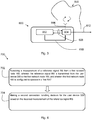
- Fig. 1 shows a first network node 100 according to an embodiment of the present invention.
- the first network node 100 comprises a processor 102 which is communicably coupled with communication means 108 to a transceiver 104.
- the communication means 108 are illustrated as dotted arrows between the processor 102 and the transceiver 104 in Fig. 1 .
- the communication means 108 are according to techniques well known in the art.
- the communication means 108 may e.g. be used for transfer of data or signalling between the processor 102 and the transceiver 104.
- the first network node 100 in this particular embodiment further comprises control means 110 by which the processor 102 operates (or controls) the transceiver 104.
- the control means are illustrated with the arrow from the processor 102 to the transceiver 104.
- the first network node 100 also comprises antenna means 106 coupled to the transceiver 104 for reception (and possibly transmission) in the wireless communication system 500.
- the first network node 100 may also have wired communication means 112 so that the first network node 100 e.g. can communication with other network nodes or control nodes of the wireless communication means over the wired communication means 112.
- the processor 102 is configured to receive a radio resource request for a Reference Signal (RS) to be transmitted by a user device 300 (see Fig. 6 ).
- the RS can e.g. be transmitted in the UL by the user device 300.
- the processor 102 is further configured to determine that the user device 300 is served by a second network node 600 (see Fig. 3 ) which is configured to operate in a second RAT different from the first RAT.
- the processor 102 is further configured to allocate or configure a radio resource for the RS.
- the allocation of radio resource is forwarded to the transceiver 104 which is configured to transmit a first control signal (CS1) to the user device 300, and the first control signal (CS1) indicates the allocated radio resource.
- CS1 first control signal
- the transceiver 104 is further configured to receive a RS via or on the allocated radio resource from the user device 300. Hence, the user device 300 transmits the RS in the allocated radio resource. Finally, the processor 102 is configured to measure the received RS from the user device 300.
- Fig. 2 shows a corresponding method 200.
- the method 200 may be executed in a first network node, such as the one shown in Fig. 1 .
- the method 200 comprises the step 202 of receiving a radio resource request for a RS to be transmitted by a user device 300.
- the method 200 further comprises the step 204 of determining that the user device 300 is served by a second network node 600 configured to operate in a second RAT.
- the method 200 further comprises the step 206 of allocating a radio resource for the RS.
- the method 200 further comprises the step 208 of transmitting a first control signal to the user device 300, the first control signal indicating the allocated radio resource.
- the method 200 further comprises the step 210 of receiving a RS via the allocated radio resource from the user device 300.
- the method 200 further comprises the step 212 of measuring the RS. It should be noted however that step 204 is not required to occur prior to step 212. In case the resource assignment in step 206 is independent of whether the user device 300 is served by another RAT or not, it is sufficient if 204 occurs after the measurements in step 212.
- Fig. 3 shows a second network node 600 according to an embodiment of the present invention.
- the second network node 600 is configured to operate in a second RAT different from the first RAT and is further configured to serve a user device 300.
- the second network node 600 comprises a processor 602 which is communicably coupled with communication means 608 to a transceiver 604.
- the communication means 608 are illustrated as dotted arrows between the processor 602 and the transceiver 604 in Fig. 1 .
- the communication means 608 are according to techniques well known in the art.
- the coupling means 608 may e.g. be used for transfer of data or signalling between the processor 602 and the transceiver 604.
- the second network node 600 in this particular embodiment further comprises control means 610 by which the processor 602 operates (or controls) the transceiver 604.
- the control means 610 are illustrated with the arrow from the processor 602 to the transceiver 604.
- the second network node 600 also comprises antenna means 606 coupled to the transceiver 604 for reception (and possibly transmission) in the wireless communication system 500.
- the second network node 600 may also have wired communication means 612 so that the second network node 600 e.g. can communication with other network nodes or control nodes of the wireless communication means over the wired communication means 612.
- the transceiver 604 is configured to receive a measurement of a RS from a first network node 100.
- the RS has been transmitted from the user device 300 to the first network node 100, and the first network node 100 is configured to operate in a first RAT.
- the processor 602 is configured to make a second connection handling decision for the user device 300 based on the received measurement of the RS.
- Fig. 4 shows a corresponding method 200.
- the method 200 may be executed in a second network node 600, such as the one shown in Fig. 3 .
- the method 700 comprises the step 702 of receiving a measurement of a RS from a first network node 100 configured to operate in a first RAT.
- the RS is transmitted from a user device 300 to the first network node 100.
- the user device 300 is served by the second network node 700.
- the method further comprise the step 704 of making a second connection handling decision for the user device 300 based on the received measurement of the RS.
- the first network node 100 and the second network node 600 may be a (radio) network node 300 or an access node or an access point or a base station, e.g. a Radio Base Station (RBS), which in some networks may be referred to as transmitter, "eNB", “eNodeB”, “NodeB” or “B node”, depending on the technology and terminology used.
- the radio network nodes may be of different classes such as e.g. macro eNodeB, home eNodeB or pico base station, based on transmission power and thereby also cell size.
- the radio network node can be a Station (STA), which is any device that contains an IEEE 802.11-conformant Media Access Control (MAC) and Physical Layer (PHY) interface to the Wireless Medium (WM).
- STA Station
- MAC Media Access Control
- PHY Physical Layer
- the target RAT (RAT1 associated with the first network node 100) determines a resource allocation or configuration (e.g. the time pattern, radio resources, and an identity) of an UL Reference Signal (URS) for the user device 300 and sends this allocation or configuration to the user device 300, either directly or through the source RAT (RAT2 associated with the second network node 600).
- the radio resource request can be sent from the second network node 600 or the user device 300 to the first network node.
- the radio resource request is described more in the following disclosure.
- Measurements on the URS are performed by the first network node 100.
- the benefit from using the URS rather than a downlink reference signal is that there is no need for additional DL reference signals to support inter-RAT connection handling. Adding an additional RS for this purpose would reduce the available capacity in the cell served by the first network node 100.
- the connection handling decision may for example be to add a connection between the user device 300 and the network node when the signal quality exceeds a threshold, or where the signal quality is measured by comparing the received signal power of a reference signal compared to the total received power (interference), or by removing a connection if the signal quality is lower than a threshold.
- the decision can be made based on received signal power.
- the benefit of using signal quality is that this takes the interference of the uplink into account, whereas the benefit of using received signal power is that reflects the signal propagation in both uplink and downlink.
- connection handling we mean actions related to managing the connection(s) between the user device 300 and one or more network nodes, including such functionality as adding, removing or modifying a connection between one user device 300 and one network node.
- connection handling are:
- Connection handling may also be used to modify existing connections to adjust the parameters used for transmission of information, e.g. change radio resource parameters assigned to control channels.
- One example of this is that different URS may be used by the user device 300 depending on the distance between the user device 300 and the first network node 100. It is also possible to modify the connection in a similar manner such that if the measurement is above or below a threshold, the connection can be modified, e.g. by using a lower power for the URS if the user device 300 is located close to the network node.
- connection handling is that that a network node receives measurements, makes a decision, execute the decision, and inform the user device 300 so that the user device 300 can be configured accordingly.
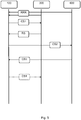
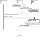
- Fig. 5 illustrates signalling aspects of further embodiments of the present invention.
- the first network node 100 receives a radio resource request RRR from the user device 300 or from the second network node 600. In response to the RRR the first network node 100 transmits the first control signal CS1 to the user device 300.
- the user device 300 in response to reception of the first control signal CS1 transmits a reference signal RS via or on the radio resource allocation indicated in the received CS1.
- the first network node 100 transmits a second control signal (CS2) to the second network node 600.
- the second control signal SC2 indicates a first connection handling decision made by the first network node 100.
- the first network node 100 receives a third control signal (CS3) from the second network node 600.
- the third control signal indicates a second connection handling decision for the user device 300 made by the second network node 600.
- the first network node 100 updates the allocated radio resource based on the first connection handling decision or the second connection handling decision.
- the first network node 100 thereafter transmits an updated first control signal CS1 indicating an updated allocated radio resource to the user device 300. This is illustrated with the dotted box and arrow.
- Fig. 6 shows a wireless communication system according to an embodiment of the present invention. It is shown how the first network node 100 of the first RAT transmits a first control signal CS1 to the user device 300.
- the first control signal CS1 indicates the radio resource allocation/configuration for a reference signal RS.
- the user device 300 derives the allocation and transmits the reference signal RS in the UL in the allocated radio resource. It is also illustrated with the dotted two way arrow that the second network node 600 of the second RAT serves the user device 300 during the described procedure.
- the first network node 100 is in the following a target network node belonging to a target first RAT (RAT1).
- the second network node 600 is a source network node belonging to a source second RAT (RAT2).
- the allocation of radio resource for the URS may be based on this information (e.g. measurements, or service information) provided by the user device 300 or by the source RAT via e.g. the second network node 600.
- the benefit of including this information is that the first RAT can select an URS that is suitable for the user device 300, e.g. an URS that the user device 300 will be able to use (e.g.
- the first RAT cannot use this additional information when selecting a suitable URS, the first RAT will have to select one based on the worst case, e.g. assume highest mobility, which will lead to a higher resource usage, both over the air and in the network node receiver.
- the target first RAT can select an URS that is suitable for the user device 300, e.g. an URS that the user device 300 will be able to use (e.g.
- the first network node 100 matches the user device capabilities, and possible to transmit without impacting the Quality of Service (QoS) of ongoing services), and that will be frequent enough to accurately allow the first network node 100 to track the mobility and channel characteristics of the user device 300, e.g. depending on the user device 300 velocity. If the first RAT is not able to select a suitable URS, it will have to select one based on the worst case, e.g. assume highest mobility, which will lead to a higher resource usage, both over the air and in the network node receiver.
- QoS Quality of Service
- URS resource request Acknowledgment (ACK): this is sent from first network node 100 to the second network node 600.
- the benefit of this is similar as stated above.
- the second network node 600 may take this into account for Radio Resource Management (RRM) purposes, e.g. this pattern indicates when the user device 300 will transmit the URS and may not be available for UL/DL transmission for the second network node 600.
- RRM Radio Resource Management
- URS configuration this is similar to URS resource request ACK but sent to a user device 300.
- the URS configuration enables the end to end transmission from the first network node 100 to the user device 300.
- URS measurement configuration this is a measurement configuration to the first network node 100 indicating the identity or network address of the second network node and possibly what parameters (e.g. thresholds, time-to-trigger, etc.) that should be used in the measurement phase in the first network node 100.
- the benefit of including this information is that the measurement reports that are sent from the first network node 100 may be reduced, since the second network node 600 can indicate when the reports are important to be transmitted since there is no need to send unnecessary reports increasing overhead.
- URS decision configuration this is similar to the URS measurement configuration but this is used when first network node 100 performs a connection decision. This is a configuration to the first network node 100 indicating the identity or network address of the second network node and possibly what parameters (thresholds, time-to-trigger, etc.) that should be used in the decision (when applicable) in the first network node 100. The benefit of including this information is that the first network node 100 can make better decisions since the second network node 600 who has most information available regarding the user device 300 remains in partial control of the decision by deciding the criteria for the decision.
- Measurement report this report is sent from the first network node 100 to the second network node 600.
- the measurement report includes the result from the measurement, e.g. a user device 300 identity, the signal strength or the radio quality, and the radio entity identity.
- radio entity we mean the entity for which the signals are reported, which can be a cell, antenna or group of antennas.
- the benefit these measurements is that the URS can be used for measurement decisions, rather than relying on the normal measurement report from the user device 300 to the second network node 600, and therefore, this is needed to achieve the benefits listed for the overall solution. Therefore, there is no need to send a specific DL reference signal.
- the benefit of sending this information is to enable decisions in a different network node than the one performing the measurements.
- this indication is sent to/from the first network node 100. This includes information about a decision that was made in the network node sending this indication. This may include information about connection handling (addition/removal/modification) and associated parameters so that the network node receiving can perform the actions required for this connection handling decision. It may also include the measurement report. The benefit of including the measurement report is that this gives additional information for the receiving network node regarding the conditions at the time the decision was made and can e.g. be used to partly allocate new parameters for the connection(s) in the receiving network node.
- the first network node 100 provides measurement results to the second network node 600 (source network node) which makes a connection handing decision. After this, the first network node 100 is informed and can make additional connection handing decisions.
- the first network node 100 makes the first decision and sends a decision indication to the second network node 600, which may then make additional handling decisions. Hence a decision may be taken in the first network node 100, the second network node 600 or in both network nodes 100, 600.
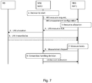
- NN2 is the only network node communicating with the UD.
- the first decision for connection handling is done in the NN2.
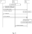
- the principle is that both NN2 and NN1 can communicate with the UD.
- the first decision for connection handling is done in the NN2.
- the UD is configured to autonomously decide when to start sending the URS used for measurements.
- the principle is that both NN2 and NN1 can communicate with the UD.
- NN2 is the only one communicating with the UD.
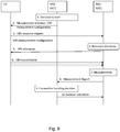
- the first decision for connection handling is done in NN1.
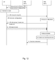
- the principle is that both NN2 and NN1 can communicate with the UD.
- the first decision for connection handling is done by NN1.
- the principle is that both NN1 and NN2 can communicate with the UD.
- the first decision for connection handling is done by NN1.
- the receiver device (UD) 300 discussed in the present disclosure may be a user device, such as a User Equipment (UE), mobile station (MS), wireless terminal or mobile terminal is enabled to communicate wirelessly in a wireless communication system, sometimes also referred to as a cellular radio system.
- the User Equipment (UE) may further be referred to as mobile telephones, cellular telephones, computer tablets or laptops with wireless capability.
- the UEs in the present context may be, for example, portable, pocket-storable, hand-held, computer-comprised, or vehicle-mounted mobile devices, enabled to communicate voice or data, via the radio access network, with another entity, such as another receiver or a server.
- the UE can be a Station (STA), which is any device that contains an IEEE 802.11-conformant Media Access Control (MAC) and Physical Layer (PHY) interface to the Wireless Medium (WM).
- STA Station
- MAC Media Access Control
- PHY Physical Layer
- any method according to the present invention may be implemented in a computer program, having code means, which when run by processing means causes the processing means to execute the steps of the method.
- the computer program is included in a computer readable medium of a computer program product.
- the computer readable medium may comprises of essentially any memory, such as a ROM (Read-Only Memory), a PROM (Programmable Read-Only Memory), an EPROM (Erasable PROM), a Flash memory, an EEPROM (Electrically Erasable PROM), or a hard disk drive.
- the present first network node and second network node comprises the necessary communication capabilities in the form of e.g., functions, means, units, elements, etc., for performing the present solution.
- means, units, elements and functions are: processors, memory, buffers, control logic, encoders, decoders, rate matchers, de-rate matchers, mapping units, multipliers, decision units, selecting units, switches, interleavers, de-interleavers, modulators, demodulators, inputs, outputs, antennas, amplifiers, receiver units, transmitter units, DSPs, MSDs, TCM encoder, TCM decoder, power supply units, power feeders, communication interfaces, communication protocols, etc. which are suitably arranged together for performing the present solution.
- the processors of the present devices may comprise, e.g., one or more instances of a Central Processing Unit (CPU), a processing unit, a processing circuit, a processor, an Application Specific Integrated Circuit (ASIC), a microprocessor, or other processing logic that may interpret and execute instructions.
- CPU Central Processing Unit
- ASIC Application Specific Integrated Circuit
- the expression "processor” may thus represent a processing circuitry comprising a plurality of processing circuits, such as, e.g., any, some or all of the ones mentioned above.
- the processing circuitry may further perform data processing functions for inputting, outputting, and processing of data comprising data buffering and device control functions, such as call processing control, user interface control, or the like.
Landscapes
- Engineering & Computer Science (AREA)
- Signal Processing (AREA)
- Computer Networks & Wireless Communication (AREA)
- Mobile Radio Communication Systems (AREA)
Claims (4)
- Premier noeud de réseau (100) pour un système de communication sans fil (500), le premier noeud de réseau (100) étant configuré pour fonctionner selon une première technique d'accès radio (RAT) et le premier noeud de réseau (100) comprenant :
un processeur (102) configuré pour :recevoir une demande de ressource radio (RRR) pour un signal de référence (RS) devant être émis par un dispositif d'utilisateur (300) ;déterminer que le dispositif d'utilisateur (300) est desservi par un second noeud de réseau (600) configuré pour fonctionner selon une seconde RAT ;affecter une ressource radio au signal de référence (RS) ;un émetteur-récepteur (104) configuré pour :émettre un premier signal de contrôle (CS1) vers le dispositif d'utilisateur (300), le premier signal de contrôle (CS1) indiquant la ressource radio affectée ;recevoir un signal de référence (RS) par l'intermédiaire de la ressource radio affectée en provenance du dispositif d'utilisateur (300) ;le processeur (102) étant configuré pour mesurer le signal de référence (RS) ;selon une première variante, le premier noeud de réseau (100) comprenant en outre :le processeur (102) configuré pour prendre une première décision de gestion de connexion pour le dispositif d'utilisateur (300) sur la base de la mesure du signal de référence (RS) ;l'émetteur-récepteur (104) configuré pour émettre un deuxième signal de contrôle (CS2) vers le second noeud de réseau (600), le deuxième signal de contrôle (CS2) indiquant la première décision de gestion de connexion ; etle processeur (102) configuré pour exécuter une gestion de connexion pour le dispositif d'utilisateur (300) selon la première décision de gestion de connexion ;selon une seconde variante à la place de première variante, le premier noeud de réseau (100) comprenant :l'émetteur-récepteur (104) configuré pour transférer la mesure du signal de référence (RS) au second noeud de réseau (600) ;l'émetteur-récepteur (104) étant configuré pour recevoir un troisième signal de contrôle (CS3) en provenance du second noeud de réseau (600), le troisième signal de contrôle indiquant une seconde décision de gestion de connexion pour le dispositif d'utilisateur (300) ; etle processeur configuré pour exécuter une gestion de connexion pour le dispositif d'utilisateur (300) selon la seconde décision de gestion de connexion. - Premier noeud de réseau (100) selon la revendication 1, dans lequel le processeur (102) est en outre configuré pour :mettre à jour la ressource radio affectée sur la base de la première décision de gestion de connexion ou de la seconde décision de gestion de connexion,l'émetteur-récepteur (104) étant en outre configuré pour :
émettre un premier signal de contrôle (CS1) mis à jour, indiquant une ressource radio affectée mise à jour vers le dispositif d'utilisateur (300). - Procédé dans un premier noeud de réseau (100) pour un système de communication sans fil (500), le premier noeud de réseau (100) étant configuré pour fonctionner selon une première technique d'accès radio (RAT) et le procédé (200) consistant à :recevoir (202) une demande de ressource radio (RRR) pour un signal de référence (RS) devant être émis par un dispositif d'utilisateur (300) ;déterminer (204) que le dispositif d'utilisateur (300) est desservi par un second noeud de réseau (600) configuré pour fonctionner selon une seconde RAT ;affecter (206) une ressource radio au signal de référence (RS) ;émettre (208) un premier signal de contrôle (CS1) vers le dispositif d'utilisateur (300), le premier signal de contrôle (CS1) indiquant la ressource radio affectée ;recevoir (210) un signal de référence (RS) par l'intermédiaire de la ressource radio affectée en provenance du dispositif d'utilisateur (300) ;mesurer (212) le signal de référence (RS) ;selon une première variante, le procédé consistant en outre à :prendre une première décision de gestion de connexion pour le dispositif d'utilisateur (300) sur la base de la mesure du signal de référence (RS) ;émettre un deuxième signal de contrôle (CS2) vers le second noeud de réseau (600), le deuxième signal de contrôle (CS2) indiquant la première décision de gestion de connexion ; etexécuter une gestion de connexion pour le dispositif d'utilisateur (300) selon la première décision de gestion de connexion ;selon une seconde variante à la place de première variante, le procédé consistant en outre à :transférer la mesure du signal de référence (RS) au second noeud de réseau (600) ;recevoir un troisième signal de contrôle (CS3) en provenance du second noeud de réseau (600), le troisième signal de contrôle indiquant une seconde décision de gestion de connexion pour le dispositif d'utilisateur (300) ; etexécuter une gestion de connexion pour le dispositif d'utilisateur (300) selon la seconde décision de gestion de connexion.
- Programme informatique comprenant un code de programme permettant, lorsque le programme informatique est exécuté par un premier noeud de réseau (100), de réaliser un procédé selon la revendication 3.
Applications Claiming Priority (1)
| Application Number | Priority Date | Filing Date | Title |
|---|---|---|---|
| PCT/EP2015/065060 WO2017001015A1 (fr) | 2015-07-02 | 2015-07-02 | Nœuds de réseau et procédés associés |
Publications (2)
| Publication Number | Publication Date |
|---|---|
| EP3300552A1 EP3300552A1 (fr) | 2018-04-04 |
| EP3300552B1 true EP3300552B1 (fr) | 2019-09-04 |
Family
ID=53682649
Family Applications (1)
| Application Number | Title | Priority Date | Filing Date |
|---|---|---|---|
| EP15739196.2A Active EP3300552B1 (fr) | 2015-07-02 | 2015-07-02 | Noeud de réseau de gestion de connexion et son procédé |
Country Status (4)
| Country | Link |
|---|---|
| US (1) | US20180139675A1 (fr) |
| EP (1) | EP3300552B1 (fr) |
| CN (1) | CN107771402B (fr) |
| WO (1) | WO2017001015A1 (fr) |
Families Citing this family (2)
| Publication number | Priority date | Publication date | Assignee | Title |
|---|---|---|---|---|
| CN106817725B (zh) * | 2015-11-30 | 2020-02-21 | 华为技术有限公司 | 无线通信的方法和装置 |
| US11589256B2 (en) * | 2017-12-22 | 2023-02-21 | Telefonaktiebolaget Lm Ericsson (Publ) | QoS in hybrid communication networks |
Family Cites Families (20)
| Publication number | Priority date | Publication date | Assignee | Title |
|---|---|---|---|---|
| FI103081B (fi) * | 1996-02-23 | 1999-04-15 | Nokia Telecommunications Oy | Kanavanvaihto matkaviestinjärjestelmässä |
| US6112093A (en) * | 1996-07-03 | 2000-08-29 | Telefonaktiebolaget Lm Ericsson | Radio communication system and method for analog and digital traffic channel allocation using a second higher threshold when allocating a digital channel |
| US7843878B2 (en) * | 2000-12-04 | 2010-11-30 | Ericsson Ab | Method and apparatus to control handoff between different wireless systems |
| ATE350868T1 (de) * | 2001-05-10 | 2007-01-15 | Nortel Networks Ltd | System und verfahren zur umleitung von kommunikation zwischen mobiltelekommunikationsnetzen mit unterschiedlichen funkzugangstechnologien |
| KR101002879B1 (ko) * | 2005-06-10 | 2010-12-21 | 삼성전자주식회사 | 이동 통신 시스템에서의 핸드오프 방법 |
| US8102802B2 (en) * | 2006-05-08 | 2012-01-24 | Motorola Mobility, Inc. | Method and apparatus for providing downlink acknowledgments and transmit indicators in an orthogonal frequency division multiplexing communication system |
| KR100980259B1 (ko) * | 2007-03-14 | 2010-09-06 | 삼성전자주식회사 | 이동통신 시스템에서 스캐닝 구간에서의 상향링크 파일럿 전송 장치 및 방법 |
| US8620320B2 (en) * | 2007-06-19 | 2013-12-31 | Motorola Mobility Llc | Methods for handing over calls between communication networks using dissimilar air interfaces |
| CN101453745B (zh) * | 2007-11-29 | 2012-09-19 | 电信科学技术研究院 | 一种小区切换过程中的测量方法、透明中继及基站 |
| JP2009231976A (ja) * | 2008-03-19 | 2009-10-08 | Nec Corp | 異なる無線アクセス方式間のハンドオーバ方法および無線通信システム |
| EP2255588B1 (fr) * | 2008-03-20 | 2018-05-09 | Telefonaktiebolaget LM Ericsson (publ) | Programmation de rapports de mesure de liaison montante |
| EP2294857B1 (fr) * | 2008-07-03 | 2014-04-09 | Telefonaktiebolaget L M Ericsson (PUBL) | Procédé et agencement dans un système de télécommunication |
| KR101550463B1 (ko) * | 2008-12-30 | 2015-09-14 | 엘지전자 주식회사 | 핸드오버 방법 |
| JP4981929B2 (ja) * | 2010-01-08 | 2012-07-25 | シャープ株式会社 | 無線通信システム、移動局装置、基地局装置、無線通信方法および集積回路 |
| KR101641106B1 (ko) * | 2010-06-09 | 2016-07-20 | 삼성전자주식회사 | 계층 셀에서의 매크로 기지국, 소형 기지국 및 단말의 통신 방법 |
| US9801174B2 (en) * | 2011-01-10 | 2017-10-24 | Samsung Electronics Co., Ltd. | Method and apparatus for obtaining identifier of small cell in wireless communication system having hierarchical cell structure |
| US9332474B2 (en) * | 2012-05-17 | 2016-05-03 | Telefonaktiebolaget L M Ericsson | Signaling support for multi sector deployment in cellular communications |
| US10356640B2 (en) * | 2012-11-01 | 2019-07-16 | Intel Corporation | Apparatus, system and method of cellular network communications corresponding to a non-cellular network |
| KR102316996B1 (ko) * | 2015-04-10 | 2021-10-25 | 삼성전자주식회사 | 간섭 제거 방법 및 그 장치 |
| US10038525B2 (en) * | 2015-04-27 | 2018-07-31 | Nokia Solutions And Networks Oy | Management of coordinated multi-point communication |
-
2015
- 2015-07-02 EP EP15739196.2A patent/EP3300552B1/fr active Active
- 2015-07-02 WO PCT/EP2015/065060 patent/WO2017001015A1/fr not_active Ceased
- 2015-07-02 CN CN201580080899.5A patent/CN107771402B/zh active Active
-
2017
- 2017-12-28 US US15/856,104 patent/US20180139675A1/en not_active Abandoned
Non-Patent Citations (1)
| Title |
|---|
| None * |
Also Published As
| Publication number | Publication date |
|---|---|
| US20180139675A1 (en) | 2018-05-17 |
| WO2017001015A1 (fr) | 2017-01-05 |
| EP3300552A1 (fr) | 2018-04-04 |
| CN107771402A (zh) | 2018-03-06 |
| CN107771402B (zh) | 2020-08-07 |
Similar Documents
| Publication | Publication Date | Title |
|---|---|---|
| JP7763894B2 (ja) | 基地局、ユーザ機器および方法 | |
| KR102125786B1 (ko) | 핸드오버 방법, 기지국 및 단말 기기 | |
| EP3477996B1 (fr) | Réseau avec terminaux d2d | |
| CN112567806B (zh) | 网络节点、无线设备及其执行的用于处理链路切换的方法 | |
| EP2767119B1 (fr) | Équipement d'utilisateur et noeud de réseau de radiocommunication, et procédés associés pour des communications entre des dispositifs | |
| CN106031292B (zh) | 用于双连接性中的特定辅小区选择的处置的方法和系统 | |
| US20200077314A1 (en) | Method for measurement report event operation and network signaling in ue autonomous handover | |
| US20090291686A1 (en) | Autonomous connectivity between a mobile station and multiple network elements for minimizing service discontinuities during handovers in a wireless communication system | |
| JP6279487B2 (ja) | 無線通信システムにおけるサービス提供方法及びシステム | |
| US20090290555A1 (en) | Autonomous anonymous association between a mobile station and multiple network elements in a wireless communication system | |
| US9510259B2 (en) | Methods and arrangement for handling a data transferral in a cellular network | |
| CN109565699B (zh) | 网络节点及其方法 | |
| CN102905306B (zh) | 小区切换方法、基站设备和用户设备 | |
| EP4000307B1 (fr) | Configuration du handover conditionnel dans un réseau de communication sans fil | |
| WO2016095637A1 (fr) | Appareil, dispositif, et procédé de traitement pour la réalisation de communication haute fréquence sur la base de zone morte | |
| EP4059266B1 (fr) | Resélection de cellule basée sur le groupe ue | |
| US20190132783A1 (en) | Access method, user equipment, control device, and communications system | |
| US9107118B2 (en) | Method for signaling a mobile wireless device to switch to a preset carrier in a multi-carrier 4G network | |
| EP3300552B1 (fr) | Noeud de réseau de gestion de connexion et son procédé | |
| WO2019024993A1 (fr) | Nœud de réseau commandant une cellule de système de communication sans fil, dispositif client sans fil et procédés associés | |
| WO2025131259A1 (fr) | Procédés d'itinérance pour dispositifs à liaisons multiples | |
| CN120730474A (zh) | 针对切片之间的预期资源管理的支持 |
Legal Events
| Date | Code | Title | Description |
|---|---|---|---|
| STAA | Information on the status of an ep patent application or granted ep patent |
Free format text: STATUS: THE INTERNATIONAL PUBLICATION HAS BEEN MADE |
|
| PUAI | Public reference made under article 153(3) epc to a published international application that has entered the european phase |
Free format text: ORIGINAL CODE: 0009012 |
|
| STAA | Information on the status of an ep patent application or granted ep patent |
Free format text: STATUS: REQUEST FOR EXAMINATION WAS MADE |
|
| 17P | Request for examination filed |
Effective date: 20171227 |
|
| AK | Designated contracting states |
Kind code of ref document: A1 Designated state(s): AL AT BE BG CH CY CZ DE DK EE ES FI FR GB GR HR HU IE IS IT LI LT LU LV MC MK MT NL NO PL PT RO RS SE SI SK SM TR |
|
| AX | Request for extension of the european patent |
Extension state: BA ME |
|
| DAV | Request for validation of the european patent (deleted) | ||
| DAX | Request for extension of the european patent (deleted) | ||
| GRAP | Despatch of communication of intention to grant a patent |
Free format text: ORIGINAL CODE: EPIDOSNIGR1 |
|
| STAA | Information on the status of an ep patent application or granted ep patent |
Free format text: STATUS: GRANT OF PATENT IS INTENDED |
|
| RIC1 | Information provided on ipc code assigned before grant |
Ipc: H04W 36/28 20090101ALN20190312BHEP Ipc: H04W 36/14 20090101ALI20190312BHEP Ipc: H04W 36/00 20090101AFI20190312BHEP |
|
| INTG | Intention to grant announced |
Effective date: 20190410 |
|
| GRAS | Grant fee paid |
Free format text: ORIGINAL CODE: EPIDOSNIGR3 |
|
| GRAA | (expected) grant |
Free format text: ORIGINAL CODE: 0009210 |
|
| STAA | Information on the status of an ep patent application or granted ep patent |
Free format text: STATUS: THE PATENT HAS BEEN GRANTED |
|
| AK | Designated contracting states |
Kind code of ref document: B1 Designated state(s): AL AT BE BG CH CY CZ DE DK EE ES FI FR GB GR HR HU IE IS IT LI LT LU LV MC MK MT NL NO PL PT RO RS SE SI SK SM TR |
|
| REG | Reference to a national code |
Ref country code: GB Ref legal event code: FG4D |
|
| REG | Reference to a national code |
Ref country code: CH Ref legal event code: EP |
|
| REG | Reference to a national code |
Ref country code: AT Ref legal event code: REF Ref document number: 1177156 Country of ref document: AT Kind code of ref document: T Effective date: 20190915 |
|
| REG | Reference to a national code |
Ref country code: DE Ref legal event code: R096 Ref document number: 602015037169 Country of ref document: DE |
|
| REG | Reference to a national code |
Ref country code: IE Ref legal event code: FG4D |
|
| REG | Reference to a national code |
Ref country code: NL Ref legal event code: MP Effective date: 20190904 |
|
| REG | Reference to a national code |
Ref country code: LT Ref legal event code: MG4D |
|
| PG25 | Lapsed in a contracting state [announced via postgrant information from national office to epo] |
Ref country code: NO Free format text: LAPSE BECAUSE OF FAILURE TO SUBMIT A TRANSLATION OF THE DESCRIPTION OR TO PAY THE FEE WITHIN THE PRESCRIBED TIME-LIMIT Effective date: 20191204 Ref country code: BG Free format text: LAPSE BECAUSE OF FAILURE TO SUBMIT A TRANSLATION OF THE DESCRIPTION OR TO PAY THE FEE WITHIN THE PRESCRIBED TIME-LIMIT Effective date: 20191204 Ref country code: SE Free format text: LAPSE BECAUSE OF FAILURE TO SUBMIT A TRANSLATION OF THE DESCRIPTION OR TO PAY THE FEE WITHIN THE PRESCRIBED TIME-LIMIT Effective date: 20190904 Ref country code: LT Free format text: LAPSE BECAUSE OF FAILURE TO SUBMIT A TRANSLATION OF THE DESCRIPTION OR TO PAY THE FEE WITHIN THE PRESCRIBED TIME-LIMIT Effective date: 20190904 Ref country code: HR Free format text: LAPSE BECAUSE OF FAILURE TO SUBMIT A TRANSLATION OF THE DESCRIPTION OR TO PAY THE FEE WITHIN THE PRESCRIBED TIME-LIMIT Effective date: 20190904 Ref country code: FI Free format text: LAPSE BECAUSE OF FAILURE TO SUBMIT A TRANSLATION OF THE DESCRIPTION OR TO PAY THE FEE WITHIN THE PRESCRIBED TIME-LIMIT Effective date: 20190904 |
|
| PG25 | Lapsed in a contracting state [announced via postgrant information from national office to epo] |
Ref country code: ES Free format text: LAPSE BECAUSE OF FAILURE TO SUBMIT A TRANSLATION OF THE DESCRIPTION OR TO PAY THE FEE WITHIN THE PRESCRIBED TIME-LIMIT Effective date: 20190904 Ref country code: GR Free format text: LAPSE BECAUSE OF FAILURE TO SUBMIT A TRANSLATION OF THE DESCRIPTION OR TO PAY THE FEE WITHIN THE PRESCRIBED TIME-LIMIT Effective date: 20191205 Ref country code: RS Free format text: LAPSE BECAUSE OF FAILURE TO SUBMIT A TRANSLATION OF THE DESCRIPTION OR TO PAY THE FEE WITHIN THE PRESCRIBED TIME-LIMIT Effective date: 20190904 Ref country code: LV Free format text: LAPSE BECAUSE OF FAILURE TO SUBMIT A TRANSLATION OF THE DESCRIPTION OR TO PAY THE FEE WITHIN THE PRESCRIBED TIME-LIMIT Effective date: 20190904 Ref country code: AL Free format text: LAPSE BECAUSE OF FAILURE TO SUBMIT A TRANSLATION OF THE DESCRIPTION OR TO PAY THE FEE WITHIN THE PRESCRIBED TIME-LIMIT Effective date: 20190904 |
|
| REG | Reference to a national code |
Ref country code: AT Ref legal event code: MK05 Ref document number: 1177156 Country of ref document: AT Kind code of ref document: T Effective date: 20190904 |
|
| PG25 | Lapsed in a contracting state [announced via postgrant information from national office to epo] |
Ref country code: PT Free format text: LAPSE BECAUSE OF FAILURE TO SUBMIT A TRANSLATION OF THE DESCRIPTION OR TO PAY THE FEE WITHIN THE PRESCRIBED TIME-LIMIT Effective date: 20200106 Ref country code: IT Free format text: LAPSE BECAUSE OF FAILURE TO SUBMIT A TRANSLATION OF THE DESCRIPTION OR TO PAY THE FEE WITHIN THE PRESCRIBED TIME-LIMIT Effective date: 20190904 Ref country code: RO Free format text: LAPSE BECAUSE OF FAILURE TO SUBMIT A TRANSLATION OF THE DESCRIPTION OR TO PAY THE FEE WITHIN THE PRESCRIBED TIME-LIMIT Effective date: 20190904 Ref country code: NL Free format text: LAPSE BECAUSE OF FAILURE TO SUBMIT A TRANSLATION OF THE DESCRIPTION OR TO PAY THE FEE WITHIN THE PRESCRIBED TIME-LIMIT Effective date: 20190904 Ref country code: EE Free format text: LAPSE BECAUSE OF FAILURE TO SUBMIT A TRANSLATION OF THE DESCRIPTION OR TO PAY THE FEE WITHIN THE PRESCRIBED TIME-LIMIT Effective date: 20190904 Ref country code: AT Free format text: LAPSE BECAUSE OF FAILURE TO SUBMIT A TRANSLATION OF THE DESCRIPTION OR TO PAY THE FEE WITHIN THE PRESCRIBED TIME-LIMIT Effective date: 20190904 Ref country code: PL Free format text: LAPSE BECAUSE OF FAILURE TO SUBMIT A TRANSLATION OF THE DESCRIPTION OR TO PAY THE FEE WITHIN THE PRESCRIBED TIME-LIMIT Effective date: 20190904 |
|
| PG25 | Lapsed in a contracting state [announced via postgrant information from national office to epo] |
Ref country code: IS Free format text: LAPSE BECAUSE OF FAILURE TO SUBMIT A TRANSLATION OF THE DESCRIPTION OR TO PAY THE FEE WITHIN THE PRESCRIBED TIME-LIMIT Effective date: 20200224 Ref country code: SK Free format text: LAPSE BECAUSE OF FAILURE TO SUBMIT A TRANSLATION OF THE DESCRIPTION OR TO PAY THE FEE WITHIN THE PRESCRIBED TIME-LIMIT Effective date: 20190904 Ref country code: SM Free format text: LAPSE BECAUSE OF FAILURE TO SUBMIT A TRANSLATION OF THE DESCRIPTION OR TO PAY THE FEE WITHIN THE PRESCRIBED TIME-LIMIT Effective date: 20190904 Ref country code: CZ Free format text: LAPSE BECAUSE OF FAILURE TO SUBMIT A TRANSLATION OF THE DESCRIPTION OR TO PAY THE FEE WITHIN THE PRESCRIBED TIME-LIMIT Effective date: 20190904 |
|
| REG | Reference to a national code |
Ref country code: DE Ref legal event code: R097 Ref document number: 602015037169 Country of ref document: DE |
|
| PLBE | No opposition filed within time limit |
Free format text: ORIGINAL CODE: 0009261 |
|
| STAA | Information on the status of an ep patent application or granted ep patent |
Free format text: STATUS: NO OPPOSITION FILED WITHIN TIME LIMIT |
|
| PG2D | Information on lapse in contracting state deleted |
Ref country code: IS |
|
| PG25 | Lapsed in a contracting state [announced via postgrant information from national office to epo] |
Ref country code: DK Free format text: LAPSE BECAUSE OF FAILURE TO SUBMIT A TRANSLATION OF THE DESCRIPTION OR TO PAY THE FEE WITHIN THE PRESCRIBED TIME-LIMIT Effective date: 20190904 Ref country code: IS Free format text: LAPSE BECAUSE OF FAILURE TO SUBMIT A TRANSLATION OF THE DESCRIPTION OR TO PAY THE FEE WITHIN THE PRESCRIBED TIME-LIMIT Effective date: 20200105 |
|
| 26N | No opposition filed |
Effective date: 20200605 |
|
| PG25 | Lapsed in a contracting state [announced via postgrant information from national office to epo] |
Ref country code: SI Free format text: LAPSE BECAUSE OF FAILURE TO SUBMIT A TRANSLATION OF THE DESCRIPTION OR TO PAY THE FEE WITHIN THE PRESCRIBED TIME-LIMIT Effective date: 20190904 |
|
| PG25 | Lapsed in a contracting state [announced via postgrant information from national office to epo] |
Ref country code: MC Free format text: LAPSE BECAUSE OF FAILURE TO SUBMIT A TRANSLATION OF THE DESCRIPTION OR TO PAY THE FEE WITHIN THE PRESCRIBED TIME-LIMIT Effective date: 20190904 |
|
| REG | Reference to a national code |
Ref country code: CH Ref legal event code: PL |
|
| REG | Reference to a national code |
Ref country code: BE Ref legal event code: MM Effective date: 20200731 |
|
| PG25 | Lapsed in a contracting state [announced via postgrant information from national office to epo] |
Ref country code: CH Free format text: LAPSE BECAUSE OF NON-PAYMENT OF DUE FEES Effective date: 20200731 Ref country code: IE Free format text: LAPSE BECAUSE OF NON-PAYMENT OF DUE FEES Effective date: 20200702 Ref country code: LI Free format text: LAPSE BECAUSE OF NON-PAYMENT OF DUE FEES Effective date: 20200731 Ref country code: LU Free format text: LAPSE BECAUSE OF NON-PAYMENT OF DUE FEES Effective date: 20200702 Ref country code: FR Free format text: LAPSE BECAUSE OF NON-PAYMENT OF DUE FEES Effective date: 20200731 |
|
| PG25 | Lapsed in a contracting state [announced via postgrant information from national office to epo] |
Ref country code: BE Free format text: LAPSE BECAUSE OF NON-PAYMENT OF DUE FEES Effective date: 20200731 |
|
| PG25 | Lapsed in a contracting state [announced via postgrant information from national office to epo] |
Ref country code: TR Free format text: LAPSE BECAUSE OF FAILURE TO SUBMIT A TRANSLATION OF THE DESCRIPTION OR TO PAY THE FEE WITHIN THE PRESCRIBED TIME-LIMIT Effective date: 20190904 Ref country code: MT Free format text: LAPSE BECAUSE OF FAILURE TO SUBMIT A TRANSLATION OF THE DESCRIPTION OR TO PAY THE FEE WITHIN THE PRESCRIBED TIME-LIMIT Effective date: 20190904 Ref country code: CY Free format text: LAPSE BECAUSE OF FAILURE TO SUBMIT A TRANSLATION OF THE DESCRIPTION OR TO PAY THE FEE WITHIN THE PRESCRIBED TIME-LIMIT Effective date: 20190904 |
|
| PG25 | Lapsed in a contracting state [announced via postgrant information from national office to epo] |
Ref country code: MK Free format text: LAPSE BECAUSE OF FAILURE TO SUBMIT A TRANSLATION OF THE DESCRIPTION OR TO PAY THE FEE WITHIN THE PRESCRIBED TIME-LIMIT Effective date: 20190904 |
|
| PGFP | Annual fee paid to national office [announced via postgrant information from national office to epo] |
Ref country code: GB Payment date: 20250529 Year of fee payment: 11 |
|
| PGFP | Annual fee paid to national office [announced via postgrant information from national office to epo] |
Ref country code: DE Payment date: 20250604 Year of fee payment: 11 |