EP3300473A1 - Component orientation determination data creation device and component orientation determination data creation method - Google Patents
Component orientation determination data creation device and component orientation determination data creation method Download PDFInfo
- Publication number
- EP3300473A1 EP3300473A1 EP15892614.7A EP15892614A EP3300473A1 EP 3300473 A1 EP3300473 A1 EP 3300473A1 EP 15892614 A EP15892614 A EP 15892614A EP 3300473 A1 EP3300473 A1 EP 3300473A1
- Authority
- EP
- European Patent Office
- Prior art keywords
- component
- orientation
- image
- determination data
- difference
- Prior art date
- Legal status (The legal status is an assumption and is not a legal conclusion. Google has not performed a legal analysis and makes no representation as to the accuracy of the status listed.)
- Granted
Links
Images



Classifications
-
- G—PHYSICS
- G06—COMPUTING OR CALCULATING; COUNTING
- G06T—IMAGE DATA PROCESSING OR GENERATION, IN GENERAL
- G06T7/00—Image analysis
- G06T7/70—Determining position or orientation of objects or cameras
- G06T7/73—Determining position or orientation of objects or cameras using feature-based methods
- G06T7/74—Determining position or orientation of objects or cameras using feature-based methods involving reference images or patches
-
- G—PHYSICS
- G06—COMPUTING OR CALCULATING; COUNTING
- G06T—IMAGE DATA PROCESSING OR GENERATION, IN GENERAL
- G06T7/00—Image analysis
- G06T7/70—Determining position or orientation of objects or cameras
-
- H—ELECTRICITY
- H05—ELECTRIC TECHNIQUES NOT OTHERWISE PROVIDED FOR
- H05K—PRINTED CIRCUITS; CASINGS OR CONSTRUCTIONAL DETAILS OF ELECTRIC APPARATUS; MANUFACTURE OF ASSEMBLAGES OF ELECTRICAL COMPONENTS
- H05K13/00—Apparatus or processes specially adapted for manufacturing or adjusting assemblages of electric components
- H05K13/08—Monitoring manufacture of assemblages
-
- H—ELECTRICITY
- H05—ELECTRIC TECHNIQUES NOT OTHERWISE PROVIDED FOR
- H05K—PRINTED CIRCUITS; CASINGS OR CONSTRUCTIONAL DETAILS OF ELECTRIC APPARATUS; MANUFACTURE OF ASSEMBLAGES OF ELECTRICAL COMPONENTS
- H05K13/00—Apparatus or processes specially adapted for manufacturing or adjusting assemblages of electric components
- H05K13/08—Monitoring manufacture of assemblages
- H05K13/081—Integration of optical monitoring devices in assembly lines; Processes using optical monitoring devices specially adapted for controlling devices or machines in assembly lines
- H05K13/0818—Setup of monitoring devices prior to starting mounting operations; Teaching of monitoring devices for specific products; Compensation of drifts during operation, e.g. due to temperature shifts
-
- G—PHYSICS
- G06—COMPUTING OR CALCULATING; COUNTING
- G06T—IMAGE DATA PROCESSING OR GENERATION, IN GENERAL
- G06T2207/00—Indexing scheme for image analysis or image enhancement
- G06T2207/30—Subject of image; Context of image processing
- G06T2207/30108—Industrial image inspection
- G06T2207/30141—Printed circuit board [PCB]
-
- G—PHYSICS
- G06—COMPUTING OR CALCULATING; COUNTING
- G06V—IMAGE OR VIDEO RECOGNITION OR UNDERSTANDING
- G06V20/00—Scenes; Scene-specific elements
- G06V20/60—Type of objects
- G06V20/64—Three-dimensional [3D] objects
Definitions
- the present invention relates to a component orientation determination data creation device and component orientation determination data creation method for creating component orientation determination data used to determine a orientation of a component for components for which determining the orientation (such as top and bottom orientation, or left and right orientation) is difficult by recognizing the outer shape of the component.
- a component mounter mounts a component on a circuit board
- the component is mounted in the wrong orientation (such as the top and bottom orientation, or the left and right orientation)
- the electrodes or terminals of the component will not be connected correctly to the lands of the circuit board, a defective board will be produced. Therefore, conventionally, an image of a component picked up by a suction nozzle of the component mounter is captured from below by a camera, and a determination is made as to the orientation of the component by image processing.
- the up-down orientation of the component cannot be determined from the outer shape; however, even in this case, there are components for which there is a region for which a brightness value differs greatly between the top and bottom, and determination of the up-down orientation of the component is performed by using image processing to calculate a brightness value for a region for which the brightness value varies greatly between the top and bottom of the component, and comparing the brightness value of that region to a determination threshold.
- the region for which the brightness value differs greatly based on whether the top or bottom of the component is facing up is specified in component orientation determination data included in image processing data used in the image processing. Creation of this component orientation determination data is performed by trial and error by an experienced operator possessing data creation skills.
- Patent literature 1 JP-A-H2-44235
- the present invention enables appropriate component orientation determination data to be easily created in a short time, even for an operator who is inexperienced in component orientation determination data creation.
- the present invention is a component orientation determination data creation device for creating component orientation determination data used in a component orientation determination system that determines an orientation of the component by comparing a brightness value of a determination region specified in the component orientation determination data within an image of the component captured by a camera with a determination threshold
- the component orientation determination data creation device including: a difference image calculating means configured to calculate a difference image between an image of the component in a correct orientation and an image of the component in another orientation by acquiring multiple images of the component in different orientations by changing the orientation with respect to the camera of the component that is the target for the component orientation determination data creation; and a component orientation determination data calculating means configured to obtain a region for which the brightness difference within the difference image is maximized or is equal to or greater than a specified value, and to calculate the component orientation determination data including position information that specifies the determination region inside the region.
- the present invention by calculating a difference image between an image of the component in the correct orientation and an image of the component in another orientation, it is possible to easily automatically determine a region for which the brightness difference between the image of the component in the correct orientation and the image of the component in the other orientation is greatest or equal to or greater than a specified value (that is, a region by which the two images can be clearly distinguished) from a waveform of the brightness difference of the difference image.
- a specified value that is, a region by which the two images can be clearly distinguished
- the imaging conditions for example, camera exposure time, lighting pattern, illumination conditions such as illumination brightness
- the maximum value of the brightness difference within the difference image also changes.
- the larger the brightness difference the easier it is to distinguish between the two images, meaning that it is possible that the optimal imaging conditions will change depending on the shape, material, surface finish, and so on of the component for which component orientation determination data is being created.
- processing for obtaining the determination region by calculating the difference image using the multiple images of the component in different orientations under changed imaging conditions may be repeated, the imaging conditions for which the brightness difference and/or the surface area of the determination is maximized from all the imaging conditions may be selected as optimal imaging conditions, and information of those optimal imaging conditions may be included in the component orientation determination data.
- component orientation determination data that includes information of optimal imaging conditions to be easily created in a short time, even for an operator who is inexperienced in component orientation determination data creation.
- a determination threshold may be calculated based on the brightness value of the determination region of the image of the component in the correct orientation, and the brightness value of the determination region of the image of the component in a different orientation or the brightness difference of the determination region of the difference image, and the calculated determination threshold may be included in the component orientation determination data.
- component orientation determination data that includes an optimal threshold for which it is easy to distinguish between an image of the component in the correct orientation and an image of the component in a difference orientation to be easily created in a short time, even for an operator who is inexperienced in component orientation determination data creation.
- the orientations of the component required for creating component orientation determination data will vary based on the shape and so on of the component. For example, when creating component orientation determination data for determining vertical flipping of a component for which determination of the vertical flipping (upside down flipping) is difficult based on image recognition of an outer shape of the component, an image of the component in the correct orientation and an image of the component in a vertically flipped orientation may be acquired, and a difference image between the two images calculated.
- an image of the component in the correct orientation, and images of the component flip-rotated 90 degrees, 180 degrees, 270 degrees may be acquired, and three difference images between each of the following may be calculated: the image of the component in the correct orientation and the image of the component flip-rotated 90 degrees, the image of the component in the correct orientation and the image of the component flip-rotated 180 degrees, and the image of the component in the correct orientation and the image of the component flip-rotated 270 degrees; then, based on the three calculated difference images, each of the regions for which the brightness differences is maximized or equal to or greater than a specified value may be obtained and the determination region in each of the regions may be set, and the component orientation determination data may be calculated including position information that specifies the determination regions of all of the three difference images.
- an image of the component in the correct orientation, and images of the component horizontally-rotated 90 degrees, 180 degrees, 270 degrees may be acquired and three difference images may be calculated between each of: the image of the component in the correct orientation and the image of the component horizontally-rotated 90 degrees, the image of the component in the correct orientation and the image of the component horizontally-rotated 180 degrees, and the image of the component in the correct orientation and the image of the component horizontally-rotated 270 degrees, and, based on the three calculated difference images, each of the regions for which the brightness differences is maximized or equal to or greater than a specified value may be obtained and a determination region candidate may be set in each of the regions, and the determination region candidate from the determination region candidates of all of the three difference images for which the brightness difference with respect to the image of the component in the correct orientation and/or the surface area is maximized may be selected as the final determination region
- the present invention may include an indicating means configured to indicate to an operator an orientation of the component to image in order to acquire the multiple images of the component in multiple orientations required for the component orientation determination data, and the configuration may be such that the operator, in accordance with indications of the indicating means, sets the component at an imaging position in an orientation indicated, imaging is performed by the camera, and an image of the component in the indicated orientation is acquired. In this manner, it is possible to easily acquire images of the component in the orientations required for creation of component orientation determination data, even for an operator who is inexperienced in component orientation determination data creation.
- the configuration may be provided with an input means for an operator to enter an orientation of the component to be imaged by the camera.
- an operator can decide the orientation of the component set at the imaging position themselves, enter data for the orientation of that component, capture images of the component required for creating the component orientation determination data, and then create the component orientation determination data.
- the component orientation determination data creation device is provided with computer 11 such as a personal computer, camera 12 that acquires grayscale images of a component for which component orientation determination data is to be created, input device 13 (input means) such as a keyboard, mouse, or touch panel, display device 14 such as a liquid crystal display or CRT, and storage device 15 that stores the component orientation determination data creation program of fig. 2 , which is described later, and the like.
- computer 11 such as a personal computer
- camera 12 that acquires grayscale images of a component for which component orientation determination data is to be created
- input device 13 input means
- display device 14 such as a liquid crystal display or CRT
- storage device 15 that stores the component orientation determination data creation program of fig. 2 , which is described later, and the like.
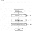
- Computer 11 creates the image processing data used in image processing of a component picked up by a suction nozzle of a component mounter, and creates component orientation determination data for determining the orientation of a component for which it is difficult to determine the orientation (such as top and bottom orientation, or left and right orientation) by recognizing the outer shape by performing the component orientation determination data creation program of fig. 2 , by which component image acquisition processing (step 101) is performed by the component image acquisition means, difference image calculating processing (step 102) is performed by the difference image calculating means, and component orientation determination data calculating processing (step 103) is performed by the component orientation determination data calculating means.
- the component orientation determination data is included in image processing data, and when image processing of a component picked up by a suction nozzle of a component mounter is performed, the orientation of the component is determined by comparing the brightness value of a determination region within the image of the component specified in the component orientation determination data with a determination threshold.
- component image acquisition processing processing of imaging after changing the orientation of the component for which component orientation determination data is being created with respect to camera 12 is repeated, such that multiple images of the component in different orientations required for creating the component orientation determination data are acquired.
- an operator performs work of setting the component at the imaging position, but, because the operator may not know the orientations of the component required for creating component orientation determination data, to acquire images of the component in the multiple orientations required for creating the component orientation determination data, an indicating function (indicating means) is provided to indicate the orientation of the component to be imaged to the operator, and when imaging a component for which data of the component orientations required for component orientation determination data is registered in storage device 15, the orientations of the component to be imaged are indicated to the operator via a display or sound of display device 14.
- an operator may enter the orientation of the component to be imaged by camera 12 using input device 13, so, when imaging a new component for which data of the orientations of the component required for creating component orientation determination data has not been registered, the operator can decide the orientation of the component set at the imaging position themselves, enter data for the orientation of that component, and then capture images of the component required for creating the component orientation determination data.
- the two or more components can be set at the imaging positions in different orientations, and the two or more components can be imaged together in the field of range of camera 12, such that an image with two or more components in different orientations lined up can be acquired with one imaging.
- a single component may be placed in the field of view of camera 12 and only one orientation captured during one imaging.
- difference image calculating processing a difference image is calculated between an image of the component in the correct orientation selected from the multiple images of the component in difference orientations, and an image of the component in a different orientation.
- the detailed calculation method of this difference image is described later using three examples.
- component orientation determination data calculating processing a region within the difference image for which the brightness difference is maximized or equal to or greater than a specified value (that is, a region that can be used to clearly distinguish between an image of the component in the correct orientation and an image of the component in a different orientation) is obtained, and component orientation determination data that includes position information specifying the determination region within the region used for determining the orientation of the component is calculated.
- a specified value that is, a region that can be used to clearly distinguish between an image of the component in the correct orientation and an image of the component in a different orientation
- the imaging conditions for example, camera 12 exposure time, lighting pattern, illumination conditions such as illumination brightness
- the maximum value of the brightness difference within the difference image also changes.
- the larger the brightness difference the easier it is to distinguish between the two images, meaning that it is possible that the optimal imaging conditions will change depending on the shape, material, surface finish, and so on of the component for which component orientation determination data is being created.
- processing for obtaining the determination region by calculating the difference image using the multiple images of the component in different orientations under changed imaging conditions is repeated a given number of times, the imaging conditions for which the brightness difference and/or the surface area of the determination is maximized from all the imaging conditions are selected as optimal imaging conditions, and information of those optimal imaging conditions is included in the component orientation determination data.
- a determination threshold is calculated based on the brightness value of the determination region of the image of the component in the correct orientation, and the brightness value of the determination region of the image of the component in a different orientation or the brightness difference of the determination region of the difference image, and the calculated determination threshold is included in the component orientation determination data.
- the orientations of the component required for creating component orientation determination data will vary based on the shape and so on of the component.
- the resistor component shown in fig. 3 because the component is a flat cuboid shape and the component thickness is small, it is sufficient to determine only vertical flipping (up and down flipping) (the horizontal rotation angle can be determined by image recognition of the outer shape of the component).
- it is difficult to determine vertical flipping by image recognition of the outer shape of the component it is necessary to create component orientation determination data for determining vertical flipping. In this case, as shown in fig. 3 , it is sufficient to acquire an image of the component in the correct orientation (normal pickup) and an image of the component flipped vertically (upside-down pickup).
- the component orientation determination data of the resistor component is created by the processing of [1-1] to [1-7] below.
- the component orientation determination data of the capacitor component is created by the processing of [2-1] to [2-9] below.
- component orientation determination data of the capacitor component includes a total of five determination regions.
- the final determination region is the logical sum of the determination regions obtained in the three difference images shown in figs. 6(a) to (c) .
- the component is a flat cuboid, it is sufficient to determine the correct orientation (0 degrees) and orientations horizontally rotated by 90 degrees, 180 degrees, and 270 degrees, however, because it is difficult to determine the four orientations above by image recognition of the outer shape of the component, it is necessary to create component orientation determination data for determining the above four orientations. In this case, as shown in fig. 7 , it is sufficient to acquire an image of the component in the correct orientation (0 degrees), and images of the component rotated horizontally by 90 degrees, 180 degrees, and 270 degrees.
- the component orientation determination data of the BGA component is created by the processing of [3-1] to [3-9] below.
- two determination region candidates each are set, and four determination region candidates are obtained by the logical sum of the determination region candidates of the three difference images, but in final processing, from these four determination region candidates, the determination region candidate for which the brightness difference with respect to the image of the component in the correct orientation (0 degrees) and/or the surface area is maximized is selected as the final determination region.
- the imaging conditions for which the brightness difference and/or the surface area of the determination is maximized from all the imaging conditions are selected as optimal imaging conditions, and information of those optimal imaging conditions is included in the component orientation determination data, it is possible for component orientation determination data that includes information of optimal imaging conditions to be easily created in a short time, even for an operator who is inexperienced in component orientation determination data creation.
- a determination threshold is calculated based on the brightness value of the determination region of the image of the component in the correct orientation, and the brightness value of the determination region of the image of the component in a different orientation or the brightness difference of the determination region of the difference image, and the calculated determination threshold is included in the component orientation determination data, it is possible to create component orientation determination data including an appropriate determination threshold for which it is easy to distinguish between an image of a component in a correct orientation and an image of a component in a different orientation easily and in a short time, even for an operator who is inexperienced in component orientation determination data creation.
- the present invention may create component orientation determination data using a component mounter, in which case, a component for which the component orientation determination data is to be created is picked up by a suction nozzle of the component mounter, and the component is imaged from below using a component recognition camera of the component mounter.
Landscapes
- Engineering & Computer Science (AREA)
- Computer Vision & Pattern Recognition (AREA)
- Physics & Mathematics (AREA)
- General Physics & Mathematics (AREA)
- Theoretical Computer Science (AREA)
- Operations Research (AREA)
- Manufacturing & Machinery (AREA)
- Microelectronics & Electronic Packaging (AREA)
- Image Analysis (AREA)
- Image Processing (AREA)
- Supply And Installment Of Electrical Components (AREA)
- Investigating Materials By The Use Of Optical Means Adapted For Particular Applications (AREA)
Abstract
Description
- The present invention relates to a component orientation determination data creation device and component orientation determination data creation method for creating component orientation determination data used to determine a orientation of a component for components for which determining the orientation (such as top and bottom orientation, or left and right orientation) is difficult by recognizing the outer shape of the component.
- When a component mounter mounts a component on a circuit board, if the component is mounted in the wrong orientation (such as the top and bottom orientation, or the left and right orientation), because the electrodes or terminals of the component will not be connected correctly to the lands of the circuit board, a defective board will be produced. Therefore, conventionally, an image of a component picked up by a suction nozzle of the component mounter is captured from below by a camera, and a determination is made as to the orientation of the component by image processing.
- Conventionally, as an example of a means for determining the orientation of a component using image processing, as disclosed in patent literature 1 (
JP-H2-44235 - Further, even if there is no polarity mark, it is sometimes possible to determine the up-down or left-right orientation of a component using only image recognition of the outer shape of the component, but in many cases the orientation of the component cannot be determined from only image recognition of the outer shape of the component.
- For example, for a component for which the outer shape is recognized as being the same by image recognition even when the component is flipped (to be upside down), the up-down orientation of the component cannot be determined from the outer shape; however, even in this case, there are components for which there is a region for which a brightness value differs greatly between the top and bottom, and determination of the up-down orientation of the component is performed by using image processing to calculate a brightness value for a region for which the brightness value varies greatly between the top and bottom of the component, and comparing the brightness value of that region to a determination threshold.
- In this case, the region for which the brightness value differs greatly based on whether the top or bottom of the component is facing up is specified in component orientation determination data included in image processing data used in the image processing. Creation of this component orientation determination data is performed by trial and error by an experienced operator possessing data creation skills.
- Patent literature 1:
JP-A-H2-44235 - As mentioned above, conventional component orientation determination data creation suffers from the problems that, because creation needs to be performed by trial and error by an experienced operator possessing data creation skills, work of creating component orientation determination data is difficult, so it is difficult for an inexperienced operator to create appropriate component orientation determination data, and, even with an experienced operator, repeated trial and error is required, meaning that creating appropriate component orientation determination data takes time.
- Thus, to solve the above problems, the present invention enables appropriate component orientation determination data to be easily created in a short time, even for an operator who is inexperienced in component orientation determination data creation.
- To solve the above problems, the present invention is a component orientation determination data creation device for creating component orientation determination data used in a component orientation determination system that determines an orientation of the component by comparing a brightness value of a determination region specified in the component orientation determination data within an image of the component captured by a camera with a determination threshold, the component orientation determination data creation device including: a difference image calculating means configured to calculate a difference image between an image of the component in a correct orientation and an image of the component in another orientation by acquiring multiple images of the component in different orientations by changing the orientation with respect to the camera of the component that is the target for the component orientation determination data creation; and a component orientation determination data calculating means configured to obtain a region for which the brightness difference within the difference image is maximized or is equal to or greater than a specified value, and to calculate the component orientation determination data including position information that specifies the determination region inside the region.
- With the present invention, by calculating a difference image between an image of the component in the correct orientation and an image of the component in another orientation, it is possible to easily automatically determine a region for which the brightness difference between the image of the component in the correct orientation and the image of the component in the other orientation is greatest or equal to or greater than a specified value (that is, a region by which the two images can be clearly distinguished) from a waveform of the brightness difference of the difference image. Thus, it is possible for appropriate component orientation determination data to be easily created in a short time, even for an operator who is inexperienced in component orientation determination data creation.
- In this case, if the imaging conditions (for example, camera exposure time, lighting pattern, illumination conditions such as illumination brightness) are changed, because the waveform of the brightness difference of the difference image changes, the maximum value of the brightness difference within the difference image also changes. The larger the brightness difference, the easier it is to distinguish between the two images, meaning that it is possible that the optimal imaging conditions will change depending on the shape, material, surface finish, and so on of the component for which component orientation determination data is being created.
- Thus, processing for obtaining the determination region by calculating the difference image using the multiple images of the component in different orientations under changed imaging conditions may be repeated, the imaging conditions for which the brightness difference and/or the surface area of the determination is maximized from all the imaging conditions may be selected as optimal imaging conditions, and information of those optimal imaging conditions may be included in the component orientation determination data. In this manner, it is possible for component orientation determination data that includes information of optimal imaging conditions to be easily created in a short time, even for an operator who is inexperienced in component orientation determination data creation.
- Further, a determination threshold may be calculated based on the brightness value of the determination region of the image of the component in the correct orientation, and the brightness value of the determination region of the image of the component in a different orientation or the brightness difference of the determination region of the difference image, and the calculated determination threshold may be included in the component orientation determination data. In this manner, it is possible for component orientation determination data that includes an optimal threshold for which it is easy to distinguish between an image of the component in the correct orientation and an image of the component in a difference orientation to be easily created in a short time, even for an operator who is inexperienced in component orientation determination data creation.
- The orientations of the component required for creating component orientation determination data will vary based on the shape and so on of the component. For example, when creating component orientation determination data for determining vertical flipping of a component for which determination of the vertical flipping (upside down flipping) is difficult based on image recognition of an outer shape of the component, an image of the component in the correct orientation and an image of the component in a vertically flipped orientation may be acquired, and a difference image between the two images calculated.
- Also, when creating the component orientation determination data used for determining the orientation of a component for which determination of the correct orientation and 90 degree, 180 degree, and 270 degree flip-rotated orientations is difficult, an image of the component in the correct orientation, and images of the component flip-rotated 90 degrees, 180 degrees, 270 degrees may be acquired, and three difference images between each of the following may be calculated: the image of the component in the correct orientation and the image of the component flip-rotated 90 degrees, the image of the component in the correct orientation and the image of the component flip-rotated 180 degrees, and the image of the component in the correct orientation and the image of the component flip-rotated 270 degrees; then, based on the three calculated difference images, each of the regions for which the brightness differences is maximized or equal to or greater than a specified value may be obtained and the determination region in each of the regions may be set, and the component orientation determination data may be calculated including position information that specifies the determination regions of all of the three difference images.
- Further, when determining the orientation of a component for which determination of the correct orientation and 90 degree, 180 degree, and 270 degree horizontally-rotated orientations is difficult, an image of the component in the correct orientation, and images of the component horizontally-rotated 90 degrees, 180 degrees, 270 degrees may be acquired and three difference images may be calculated between each of: the image of the component in the correct orientation and the image of the component horizontally-rotated 90 degrees, the image of the component in the correct orientation and the image of the component horizontally-rotated 180 degrees, and the image of the component in the correct orientation and the image of the component horizontally-rotated 270 degrees, and, based on the three calculated difference images, each of the regions for which the brightness differences is maximized or equal to or greater than a specified value may be obtained and a determination region candidate may be set in each of the regions, and the determination region candidate from the determination region candidates of all of the three difference images for which the brightness difference with respect to the image of the component in the correct orientation and/or the surface area is maximized may be selected as the final determination region.
- The present invention may include an indicating means configured to indicate to an operator an orientation of the component to image in order to acquire the multiple images of the component in multiple orientations required for the component orientation determination data, and the configuration may be such that the operator, in accordance with indications of the indicating means, sets the component at an imaging position in an orientation indicated, imaging is performed by the camera, and an image of the component in the indicated orientation is acquired. In this manner, it is possible to easily acquire images of the component in the orientations required for creation of component orientation determination data, even for an operator who is inexperienced in component orientation determination data creation.
- Alternatively, the configuration may be provided with an input means for an operator to enter an orientation of the component to be imaged by the camera. In this manner, even for a new component for which data of the orientations of the component required for creating component orientation determination data has not been registered, an operator can decide the orientation of the component set at the imaging position themselves, enter data for the orientation of that component, capture images of the component required for creating the component orientation determination data, and then create the component orientation determination data.
-
- [
Fig. 1 ]
Fig. 1 is a block diagram showing an example configuration of a component orientation determination data creation device, which is an embodiment of the present invention. - [
Fig. 2 ]
Fig. 2 is a flowchart showing the flow of processing of a component orientation determination data creation program. - [
Fig. 3 ]
Fig. 3 shows images lined up of a component in two different orientations that are required for creating component orientation determination data of a resistor component. - [
Fig. 4 ]
Fig. 4 illustrates difference image calculating processing and component orientation determination data calculating processing for creating component orientation determination data of a resistor component. - [
Fig. 5 ]
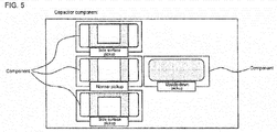
Fig. 5 shows images lined up of a component in four different orientations that are required for creating component orientation determination data of a capacitor component. - [
Fig. 6 ]
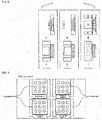
Fig. 6 illustrates difference image calculating processing and component orientation determination data calculating processing for creating component orientation determination data of a capacitor component. - [
Fig. 7 ]
Fig. 7 shows images lined up of a component in four different orientations that are required for creating component orientation determination data of a BGA component. - [
Fig. 8 ]
Fig. 8 illustrates difference image calculating processing and component orientation determination data calculating processing for creating component orientation determination data of a BGA component. - An embodiment of the present invention is described below with reference to the drawings. First, an example configuration of a component orientation determination data creation device will be described based on
fig. 1 . - The component orientation determination data creation device is provided with
computer 11 such as a personal computer,camera 12 that acquires grayscale images of a component for which component orientation determination data is to be created, input device 13 (input means) such as a keyboard, mouse, or touch panel,display device 14 such as a liquid crystal display or CRT, andstorage device 15 that stores the component orientation determination data creation program offig. 2 , which is described later, and the like. -
Computer 11 creates the image processing data used in image processing of a component picked up by a suction nozzle of a component mounter, and creates component orientation determination data for determining the orientation of a component for which it is difficult to determine the orientation (such as top and bottom orientation, or left and right orientation) by recognizing the outer shape by performing the component orientation determination data creation program offig. 2 , by which component image acquisition processing (step 101) is performed by the component image acquisition means, difference image calculating processing (step 102) is performed by the difference image calculating means, and component orientation determination data calculating processing (step 103) is performed by the component orientation determination data calculating means. The component orientation determination data is included in image processing data, and when image processing of a component picked up by a suction nozzle of a component mounter is performed, the orientation of the component is determined by comparing the brightness value of a determination region within the image of the component specified in the component orientation determination data with a determination threshold. - With component image acquisition processing, processing of imaging after changing the orientation of the component for which component orientation determination data is being created with respect to
camera 12 is repeated, such that multiple images of the component in different orientations required for creating the component orientation determination data are acquired. - Here, an operator performs work of setting the component at the imaging position, but, because the operator may not know the orientations of the component required for creating component orientation determination data, to acquire images of the component in the multiple orientations required for creating the component orientation determination data, an indicating function (indicating means) is provided to indicate the orientation of the component to be imaged to the operator, and when imaging a component for which data of the component orientations required for component orientation determination data is registered in
storage device 15, the orientations of the component to be imaged are indicated to the operator via a display or sound ofdisplay device 14. - Also, an operator may enter the orientation of the component to be imaged by
camera 12 usinginput device 13, so, when imaging a new component for which data of the orientations of the component required for creating component orientation determination data has not been registered, the operator can decide the orientation of the component set at the imaging position themselves, enter data for the orientation of that component, and then capture images of the component required for creating the component orientation determination data. - When it is possible to use two or more of the same component for which component orientation determination data is to be created, the two or more components can be set at the imaging positions in different orientations, and the two or more components can be imaged together in the field of range of
camera 12, such that an image with two or more components in different orientations lined up can be acquired with one imaging. Of course, a single component may be placed in the field of view ofcamera 12 and only one orientation captured during one imaging. - In difference image calculating processing, a difference image is calculated between an image of the component in the correct orientation selected from the multiple images of the component in difference orientations, and an image of the component in a different orientation. The detailed calculation method of this difference image is described later using three examples.
- In component orientation determination data calculating processing, a region within the difference image for which the brightness difference is maximized or equal to or greater than a specified value (that is, a region that can be used to clearly distinguish between an image of the component in the correct orientation and an image of the component in a different orientation) is obtained, and component orientation determination data that includes position information specifying the determination region within the region used for determining the orientation of the component is calculated.
- In this case, if the imaging conditions (for example,
camera 12 exposure time, lighting pattern, illumination conditions such as illumination brightness) are changed, because the waveform of the brightness difference of the difference image changes, the maximum value of the brightness difference within the difference image also changes. The larger the brightness difference, the easier it is to distinguish between the two images, meaning that it is possible that the optimal imaging conditions will change depending on the shape, material, surface finish, and so on of the component for which component orientation determination data is being created. - Thus, processing for obtaining the determination region by calculating the difference image using the multiple images of the component in different orientations under changed imaging conditions is repeated a given number of times, the imaging conditions for which the brightness difference and/or the surface area of the determination is maximized from all the imaging conditions are selected as optimal imaging conditions, and information of those optimal imaging conditions is included in the component orientation determination data.
- Further, a determination threshold is calculated based on the brightness value of the determination region of the image of the component in the correct orientation, and the brightness value of the determination region of the image of the component in a different orientation or the brightness difference of the determination region of the difference image, and the calculated determination threshold is included in the component orientation determination data.

- A: Brightness value of determination region in image of component in correct orientation
- B: Brightness value of determination region in image of component in different orientation
- Δ: Brightness difference in determination region of difference image (= A - B)
- However, the orientations of the component required for creating component orientation determination data will vary based on the shape and so on of the component. For example, for the resistor component shown in
fig. 3 , because the component is a flat cuboid shape and the component thickness is small, it is sufficient to determine only vertical flipping (up and down flipping) (the horizontal rotation angle can be determined by image recognition of the outer shape of the component). However, because it is difficult to determine vertical flipping by image recognition of the outer shape of the component, it is necessary to create component orientation determination data for determining vertical flipping. In this case, as shown infig. 3 , it is sufficient to acquire an image of the component in the correct orientation (normal pickup) and an image of the component flipped vertically (upside-down pickup). - Described below is the method for creating component orientation determination data for the resistor component shown in
fig. 3 . The component orientation determination data of the resistor component is created by the processing of [1-1] to [1-7] below. - [1-1] A component in the correct orientation (normal pickup) and a component vertically flipped (upside-down pickup) are set at the imaging position.
- [1-2] Given imaging conditions (for example,
camera 12 exposure time, lighting pattern, illumination conditions such as illumination brightness) are set, and an image of the component in the correct orientation (normal pickup) and an image of the component vertically flipped (upside-down pickup) are captured bycamera 12. - [1-3] Component outline data is automatically created by automatic creation processing of component outline data. Note that, instead of automatic creation processing of component outline data, an operator may enter the outer dimensions of the component using
input device 13. - [1-4] The image of the component in the correct orientation (normal pickup) is processed, the outer shape of the component is recognized, and the center position and rotation angle of the component are obtained; further, the image of the component vertically flipped (upside-down pickup) is processed, the outer shape of the component is recognized, and the center position and rotation angle of the component are obtained.
- [1-5] A difference image of the two images is calculated by aligning the center position and rotation angle of the component in the two images (refer to
fig. 4 ), the region within the difference region for which the brightness difference is maximized or equal to or greater than a specified value (that is, a region by which the two images can be clearly distinguished) is obtained, and position information of the region is stored in memory such as RAM along with the imaging conditions. - [1-6] The steps of [1-2] to [1-5] above are repeated a specified number of times changing the imaging conditions each time the steps of [1-2] to [1-5 are performed. Thus, for the specified number of imaging conditions, the region within the difference image for which the brightness difference is maximized or equal to or greater than a specified value is obtained, and position information of the region is stored in memory such as RAM along with the imaging conditions.
- [1-7] From all the stored imaging conditions, the imaging conditions for which the brightness difference and/or the surface area of the determination region is maximized are selected as optimal imaging conditions, and from the difference image obtained under the optimal imaging conditions, a determination region for determining the orientation of the component that is a central portion (the shape center or the center of gravity) of the region for which the brightness difference is maximized or equal to or greater than a specified value is set, and a determination threshold is calculated based on the brightness difference between the brightness value of the determination region of the image of the component in the correct orientation (normal pickup) obtained under the optimal conditions, and the brightness value of the determination region of the image of the vertically flipped component (upside-down pickup) or the brightness difference of the determination region of the difference image. In this manner, the optimal imaging conditions, the position information of the determination region, and the determination threshold are linked to the identification information or the like of the component, and stored in
storage device 15 as component orientation determination data. Note that, the size (surface area) of the determination region is set considering the tolerance for the position deviation of the image recognition such that a specified size or greater for which the determination region can definitely be recognized is guaranteed. - Further, in a case of a capacitor component as shown in
fig. 5 , because both ends of the component are square and the thickness of the component is large, it is necessary to determine based on four orientations: the correct orientation (normal pickup), 90-degree flip rotation (side surface pickup), 180-degree flip rotation (upside-down pickup), and 270-degree flip rotation (side pickup) (the rotation angle of the component in the horizontal orientation can be determined by image processing of the outer shape of the component). However, because it is difficult to determine the four orientations above by image recognition of the outer shape of the component, it is necessary to create component orientation determination data for determining the above four orientations. In this case, as shown infig. 5 , it is sufficient to acquire an image of the component in the correct orientation, and images of the component flipped vertically by 90 degrees, 180 degrees, and 270 degrees. - Described below is the method for creating component orientation determination data for the capacitor component shown in
fig. 5 . The component orientation determination data of the capacitor component is created by the processing of [2-1] to [2-9] below. - [2-1] A component in the correct orientation (normal pickup), a component vertically rotated 90 degrees (side surface pickup), a component vertically rotated 180 degrees (upside-down pickup), and a component vertically rotated 270 degrees (side surface pickup) are set at the imaging position.
- [2-2] Given imaging conditions are set and images of the component in the above four orientations are captured by
camera 12. - [2-3] Component outline data is automatically created by automatic creation processing of component outline data. Note that, instead of automatic creation processing of component outline data, an operator may enter the outer dimensions of the component using
input device 13. - [2-4] The images of the components in each orientation are processed, the outer shape of the components in each orientation are recognized, and the center position and angle rotation of the components in each orientation are obtained.
- [2-5] By aligning the center position and rotation angle of the component in the image of the component in the correct orientation (normal pickup) and the image of the component flip-rotated 90 degrees (side surface pickup), a difference image of the two images is calculated (refer to
fig. 6[a] ), the region within the difference region for which the brightness difference is maximized or equal to or greater than a specified value is obtained, and position information of the region is stored in memory such as RAM along with the imaging conditions. - [2-6] By aligning the center position and rotation angle of the component in the image of the component in the correct orientation (normal pickup) and the image of the component flip-rotated 180 degrees (upside-down pickup), a difference image of the two images is calculated (refer to
fig. 6[c] ), the region within the difference region for which the brightness difference is maximized or equal to or greater than a specified value is obtained, and position information of the region is stored in memory such as RAM along with the imaging conditions. - [2-7] By aligning the center position and rotation angle of the component in the image of the component in the correct orientation (normal pickup) and the image of the component flip-rotated 270 degrees (side surface pickup), a difference image of the two images is calculated (refer to
fig. 6[b] ), the region within the difference region for which the brightness difference is maximized or equal to or greater than a specified value is obtained, and position information of the region is stored in memory such as RAM along with the imaging conditions. - [2-8] The steps of [2-2] to [2-7] above are repeated a specified number of times changing the imaging conditions each time the steps of [2-2] to [2-7] are performed. Thus, for the specified number of imaging conditions, the region within the three difference images for which the brightness difference is maximized or equal to or greater than a specified value is obtained, and position information of the region is stored in memory such as RAM along with the imaging conditions.
- [2-9] From all the stored imaging conditions, the imaging conditions for which the brightness difference and/or the surface area of the determination region is maximized are selected as optimal imaging conditions, and from the three difference images obtained under the optimal imaging conditions, a determination region for determining the orientation of the component that is a central portion (the shape center or the center of gravity) of the region for which the brightness difference is maximized or equal to or greater than a specified value is set, and a determination threshold is calculated based on the brightness difference between the brightness value of the determination region of the image of the component in the correct orientation (normal pickup) obtained under the optimal conditions, and the brightness value of the determination region of the image of the component in a different orientation or the brightness difference of the determination region of each of the difference images. In this manner, the optimal imaging conditions, the position information of the determination region of the three difference images, and the determination threshold are linked to the identification information or the like of the component, and stored in
storage device 15 as component orientation determination data. Note that, the size (surface area) of the determination region is set considering the tolerance for the position deviation of the image recognition such that a specified size or greater for which the determination region can definitely be recognized is guaranteed. - With the two difference images shown in
fig. 6(a) and (b) , one determination region is set for each; for the difference image shown infig. 6(c) , because there are three regions for which the brightness difference is maximized or equal to or greater than a specified value, there are three determination regions set in the center portion of those regions. Thus, component orientation determination data of the capacitor component includes a total of five determination regions. The final determination region, is the logical sum of the determination regions obtained in the three difference images shown infigs. 6(a) to (c) . - Further, for the BGA component shown in
fig. 7 , because the component is a flat cuboid, it is sufficient to determine the correct orientation (0 degrees) and orientations horizontally rotated by 90 degrees, 180 degrees, and 270 degrees, however, because it is difficult to determine the four orientations above by image recognition of the outer shape of the component, it is necessary to create component orientation determination data for determining the above four orientations. In this case, as shown infig. 7 , it is sufficient to acquire an image of the component in the correct orientation (0 degrees), and images of the component rotated horizontally by 90 degrees, 180 degrees, and 270 degrees. - Described below is the method for creating component orientation determination data for the BGA component shown in
fig. 7 . The component orientation determination data of the BGA component is created by the processing of [3-1] to [3-9] below. - [3-1] A component in the correct orientation (0 degrees), a component horizontally rotated 90 degrees, a component horizontally rotated 180 degrees, and a component horizontally rotated 270 degrees are set at the imaging position.
- [3-2] Given imaging conditions are set and images of the component in the above four orientations are captured by
camera 12. - [3-3] Component outline data is automatically created by automatic creation processing of component outline data. Note that, instead of automatic creation processing of component outline data, an operator may enter the outer dimensions of the component using
input device 13. - [3-4] The images of the components in each orientation are processed, the outer shape of the components in each orientation are recognized, and the center position and angle rotation of the components in each orientation are obtained.
- [3-5] By aligning the center position and rotation angle of the component in the image of the component in the correct orientation (0 degrees) and the image of the component horizontally rotated 90 degrees, a difference image of the two images is calculated (refer to
fig. 8[a] ), the region within the difference region for which the brightness difference is maximized or equal to or greater than a specified value is obtained, and position information of the region is stored in memory such as RAM along with the imaging conditions. - [3-6] By aligning the center position and rotation angle of the component in the image of the component in the correct orientation (0 degrees) and the image of the component horizontally rotated 180 degrees, a difference image of the two images is calculated (refer to
fig. 8[b] ), the region within the difference region for which the brightness difference is maximized or equal to or greater than a specified value is obtained, and position information of the region is stored in memory such as RAM along with the imaging conditions. - [3-7] By aligning the center position and rotation angle of the component in the image of the component in the correct orientation (0 degrees) and the image of the component horizontally rotated 270 degrees, a difference image of the two images is calculated (refer to
fig. 8[c] ), the region within the difference region for which the brightness difference is maximized or equal to or greater than a specified value is obtained, and position information of the region is stored in memory such as RAM along with the imaging conditions. - [3-8] The steps of [3-2] to [3-7] above are repeated a specified number of times changing the imaging conditions each time the steps of [3-2] to [3-7] are performed. Thus, for the specified number of imaging conditions, the region within the three difference images for which the brightness difference is maximized or equal to or greater than a specified value is obtained, and position information of the region is stored in memory such as RAM along with the imaging conditions.
- [3-9] From all the stored imaging conditions, the imaging conditions for which the brightness difference and/or the surface area of the determination region is maximized are selected as optimal imaging conditions, and from the three difference images obtained under the optimal imaging conditions, a determination region candidate in a central portion (the shape center or the center of gravity) of the region for which the brightness difference is maximized or equal to or greater than a specified value is set, the logical sum of the determination region candidates of all of the three difference images is obtained, and the determination region candidate for which the brightness difference with respect to the image of the component in the correct orientation (0 degrees) and/or the surface area is maximized is selected as the final determination region. Further, a determination threshold is calculated based on the brightness value of the determination region of the image of the component in the correct orientation (0 degrees) under optimal imaging conditions, and the brightness value of the determination region of the image of the component in a different orientation or the brightness difference of the determination region of each difference image. In this manner, the optimal imaging conditions, the position information of the determination region, and the determination threshold are linked to the identification information or the like of the component, and stored in
storage device 15 as component orientation determination data. Note that, the size (surface area) of the determination region is set considering the tolerance for the position deviation of the image recognition such that a specified size or greater for which the determination region can definitely be recognized is guaranteed. - In the three difference images shown in
figs. 8(a) to (c) , two determination region candidates each are set, and four determination region candidates are obtained by the logical sum of the determination region candidates of the three difference images, but in final processing, from these four determination region candidates, the determination region candidate for which the brightness difference with respect to the image of the component in the correct orientation (0 degrees) and/or the surface area is maximized is selected as the final determination region. - With the above embodiment, by calculating a difference image between an image of the component in the correct orientation and an image of the component in another orientation, it is possible to easily automatically determine a region for which the brightness difference between the image of the component in the correct orientation and the image of the component in the other orientation is greatest or equal to or greater than a specified value (that is, a region by which the two images can be clearly distinguished) from a waveform of the brightness difference of the difference image. Thus, it is possible for appropriate component orientation determination data to be easily created in a short time, for the accuracy of component orientation determination to be improved, and for production of defective boards to be prevented, even for an operator who is inexperienced in component orientation determination data creation.
- Also, because processing for obtaining the determination region by calculating the difference image using the multiple images of the component in different orientations under changed imaging conditions is repeated, the imaging conditions for which the brightness difference and/or the surface area of the determination is maximized from all the imaging conditions are selected as optimal imaging conditions, and information of those optimal imaging conditions is included in the component orientation determination data, it is possible for component orientation determination data that includes information of optimal imaging conditions to be easily created in a short time, even for an operator who is inexperienced in component orientation determination data creation.
- Further, because a determination threshold is calculated based on the brightness value of the determination region of the image of the component in the correct orientation, and the brightness value of the determination region of the image of the component in a different orientation or the brightness difference of the determination region of the difference image, and the calculated determination threshold is included in the component orientation determination data, it is possible to create component orientation determination data including an appropriate determination threshold for which it is easy to distinguish between an image of a component in a correct orientation and an image of a component in a different orientation easily and in a short time, even for an operator who is inexperienced in component orientation determination data creation.
- Note that, the present invention may create component orientation determination data using a component mounter, in which case, a component for which the component orientation determination data is to be created is picked up by a suction nozzle of the component mounter, and the component is imaged from below using a component recognition camera of the component mounter.
- In addition, it goes without saying that the present invention is not limited to the above embodiment, and various embodiments with changes that do not extend beyond the scope of the invention are possible, such as appropriate changes to the search method of the optimal imaging conditions, or the calculation method of the determination threshold.
-
- 11: computer (difference image calculating means, component orientation determination data calculating means, indicating means); 12: camera; 13: input device (input means); 14: display device; 15: storage device
Claims (12)
- A component orientation determination data creation device for creating component orientation determination data used in a component orientation determination system that determines an orientation of the component by comparing a brightness value of a determination region specified in the component orientation determination data within an image of the component captured by a camera with a determination threshold, the component orientation determination data creation device comprising:a difference image calculating means configured to calculate a difference image between an image of the component in a correct orientation and an image of the component in another orientation by acquiring multiple images of the component in different orientations by changing the orientation with respect to the camera of the component that is the target for the component orientation determination data creation; anda component orientation determination data calculating means configured to obtain a region for which the brightness difference within the difference image is maximized or is equal to or greater than a specified value, and to calculate the component orientation determination data including position information that specifies the determination region inside the region.
- The component orientation determination data creation device according to claim 1, further including
an optimal imaging conditions search means configured to select optimal imaging conditions for which the brightness difference and/or the surface area of the determination is maximized from all the imaging conditions obtained by repeating processing of the component orientation determination data calculating means obtaining the determination region based on the difference image calculated by the difference image calculating means using the multiple images of the component in different orientations under changed imaging conditions, and include information of the selected optimal imaging conditions in the component orientation determination data. - The component orientation determination data creation device according to claim 1 or 2, wherein
the component orientation determination data calculating means calculates the determination threshold based on the brightness value of the determination region of the image of the component in the correct orientation, and the brightness value of the determination region of the image of the component in a different orientation or the brightness difference of the determination region of the difference image, and includes the calculated determination threshold in the component orientation determination data. - The component orientation determination data creation device according to any one of the claims 1 to 3, wherein
the component orientation determination data creation device is configured to create the component orientation determination data used for determining vertical flipping of a component for which determination of the vertical flipping is difficult based on image recognition of an outer shape of the component, and the difference image calculating means acquires an image of the component in the correct orientation and an image of the component that has been vertically flipped and calculates the difference image of the acquired images. - The component orientation determination data creation device according to any one of the claims 1 to 3, wherein
the component orientation determination data creation device is configured to create the component orientation determination data used for determining the orientation of a component for which determination of the correct orientation and 90 degree, 180 degree, and 270 degree flip-rotated orientations is difficult,
the difference image calculating means acquires an image of the component in the correct orientation, and images of the component flip-rotated 90 degrees, 180 degrees, 270 degrees and calculates three difference images between each of: the image of the component in the correct orientation and the image of the component flip-rotated 90 degrees, the image of the component in the correct orientation and the image of the component flip-rotated 180 degrees, and the image of the component in the correct orientation and the image of the component flip-rotated 270 degrees, and
the component orientation determination data calculating means, based on the three difference images calculated by the difference image calculating means, obtains each of the regions for which the brightness differences is maximized or equal to or greater than a specified value and sets the determination region in each of the regions, and calculates the component orientation determination data including position information that specifies the determination regions of all of the three difference images. - The component orientation determination data creation device according to any one of the claims 1 to 3, wherein
the component orientation determination data creation device is configured to create the component orientation determination data used for determining the orientation of a component for which determination of the correct orientation and 90 degree, 180 degree, and 270 degree horizontally-rotated orientations is difficult,
the difference image calculating means acquires an image of the component in the correct orientation, and images of the component horizontally-rotated 90 degrees, 180 degrees, 270 degrees and calculates three difference images between each of: the image of the component in the correct orientation and the image of the component horizontally-rotated 90 degrees, the image of the component in the correct orientation and the image of the component horizontally-rotated 180 degrees, and the image of the component in the correct orientation and the image of the component horizontally-rotated 270 degrees, and
the component orientation determination data calculating means, based on the three difference images calculated by the difference image calculating means, obtains each of the regions for which the brightness differences is maximized or equal to or greater than a specified value and sets a determination region candidate in each of the regions, and selects the determination region candidate from the determination region candidates of all of the three difference images for which the brightness difference with respect to the image of the component in the correct orientation and/or surface area is maximized as the final determination region. - The component orientation determination data creation device according to any one of the claims 1 to 6, further including
an indicating means configured to indicate to an operator an orientation of the component to image in order to acquire the multiple images of the component in multiple orientations required for the component orientation determination data,
wherein
the configuration is such that the operator, in accordance with indications of the indicating means, sets the component at an imaging position in an orientation indicated, imaging is performed by the camera, and an image of the component in the indicated orientation is acquired. - The component orientation determination data creation device according to claims 1 to 7, further including
an input means configured to allow an operator to enter the orientation of the component to be imaged by the camera. - A component orientation determination data creation method for creating component orientation determination data used in a component orientation determination system that determines an orientation of the component by comparing a brightness value of a determination region specified in the component orientation determination data within an image of the component captured by a camera with a determination threshold, the component orientation determination data creation method comprising:component image acquisition processing of acquiring multiple images of the component in different orientations that are required for creation of component orientation determination data by changing the orientation with respect to the camera of the component that is the target for the component orientation determination data creation;difference image calculating processing for calculating a difference image between an image of the component in a correct orientation selected from the multiple images of the component in difference orientations and an image of the component in another orientation; andcomponent orientation determination data calculating processing for obtaining a region for which the brightness difference within the difference image is maximized or is equal to or greater than a specified value and for calculating the component orientation determination data including position information that specifies the determination region inside the region.
- The component orientation determination data creation method according to claim 9, wherein
the component orientation determination data creation method is for creating the component orientation determination data used for determining vertical flipping of a component for which determination of the vertical flipping is difficult based on image recognition of an outer shape of the component, and
the difference image processing acquires an image of the component in the correct orientation and an image of the component that has been vertically flipped and calculates the difference image of the acquired images. - The component orientation determination data creation method according to claim 9, wherein
the component orientation determination data creation method is for creating the component orientation determination data used for determining the orientation of a component for which determination of the correct orientation and 90 degree, 180 degree, and 270 degree flip-rotated orientations is difficult,
the component image acquisition processing acquires images of the component in the correct orientation and in 90 degree, 180 degree, and 270 degree flip-rotated orientations,
the difference image calculating processing calculates three difference images between each of: the image of the component in the correct orientation and the image of the component flip-rotated 90 degrees, the image of the component in the correct orientation and the image of the component flip-rotated 180 degrees, and the image of the component in the correct orientation and the image of the component flip-rotated 270 degrees, and
the component orientation determination data calculating processing, based on the three difference images calculated by the difference image calculating method, obtains each of the regions for which the brightness differences is maximized or equal to or greater than a specified value and sets the determination region in each of the regions, and calculates the component orientation determination data including position information that specifies the determination regions of all of the three difference images. - The component orientation determination data creation method according to claim 9, wherein
the component orientation determination data creation method is for creating the component orientation determination data used for determining the orientation of a component for which determination of the correct orientation and 90 degree, 180 degree, and 270 degree horizontally-rotated orientations is difficult,
the component image acquisition processing acquires an image of the component in the correct orientation, and images of the component horizontally-rotated 90 degrees, 180 degrees, 270 degrees,
the difference image calculating processing calculates three difference images between each of: the image of the component in the correct orientation and the image of the component horizontally-rotated 90 degrees, the image of the component in the correct orientation and the image of the component horizontally-rotated 180 degrees, and the image of the component in the correct orientation and the image of the component horizontally-rotated 270 degrees, and
the component orientation determination data calculating processing, based on the three difference images calculated by the difference image calculating processing, obtains each of the regions for which the brightness differences is maximized or equal to or greater than a specified value and sets a determination region candidate in each of the regions, and selects the determination region candidate from the determination region candidates of all of the three difference images for which the brightness difference with respect to the image of the component in the correct orientation and/or surface area is maximized as the final determination region.
Applications Claiming Priority (1)
| Application Number | Priority Date | Filing Date | Title |
|---|---|---|---|
| PCT/JP2015/064655 WO2016185615A1 (en) | 2015-05-21 | 2015-05-21 | Component orientation determination data creation device and component orientation determination data creation method |
Publications (3)
| Publication Number | Publication Date |
|---|---|
| EP3300473A1 true EP3300473A1 (en) | 2018-03-28 |
| EP3300473A4 EP3300473A4 (en) | 2018-06-20 |
| EP3300473B1 EP3300473B1 (en) | 2024-01-24 |
Family
ID=57319681
Family Applications (1)
| Application Number | Title | Priority Date | Filing Date |
|---|---|---|---|
| EP15892614.7A Active EP3300473B1 (en) | 2015-05-21 | 2015-05-21 | Component orientation determination data creation device and component orientation determination data creation method |
Country Status (5)
| Country | Link |
|---|---|
| US (1) | US11357149B2 (en) |
| EP (1) | EP3300473B1 (en) |
| JP (1) | JP6480575B2 (en) |
| CN (1) | CN107535090B (en) |
| WO (1) | WO2016185615A1 (en) |
Families Citing this family (2)
| Publication number | Priority date | Publication date | Assignee | Title |
|---|---|---|---|---|
| JP6838175B2 (en) * | 2018-02-09 | 2021-03-03 | 株式会社Fuji | Trained model creation system for component image recognition and trained model creation method for component image recognition |
| JP7439129B2 (en) * | 2019-12-16 | 2024-02-27 | 株式会社Fuji | parts mounting machine |
Family Cites Families (14)
| Publication number | Priority date | Publication date | Assignee | Title |
|---|---|---|---|---|
| JPH0221247A (en) * | 1988-07-08 | 1990-01-24 | Matsushita Electric Ind Co Ltd | Detection of inside-out inversion for electronic component |
| JPH0244235A (en) | 1988-08-03 | 1990-02-14 | Matsushita Electric Ind Co Ltd | Inspection of polarity for electronic component |
| JPH06123611A (en) * | 1992-10-12 | 1994-05-06 | Shinko Electric Co Ltd | Teaching method of component attitude determination device |
| US5416335A (en) | 1994-04-15 | 1995-05-16 | Seagate Technology, Inc. | Automated visual inspection system for determining the set positions of a row of dip switches |
| US6711293B1 (en) * | 1999-03-08 | 2004-03-23 | The University Of British Columbia | Method and apparatus for identifying scale invariant features in an image and use of same for locating an object in an image |
| US6490369B1 (en) * | 1999-07-06 | 2002-12-03 | Fanuc Robotics North America | Method of viewing and identifying a part for a robot manipulator |
| US7454053B2 (en) * | 2004-10-29 | 2008-11-18 | Mitutoyo Corporation | System and method for automatically recovering video tools in a vision system |
| JP4883636B2 (en) * | 2007-09-24 | 2012-02-22 | 富士機械製造株式会社 | Electronic component orientation inspection apparatus, electronic component orientation inspection method, and electronic component placement machine |
| JP4817395B2 (en) * | 2007-10-11 | 2011-11-16 | 富士機械製造株式会社 | Component suction posture discrimination method and component suction posture discrimination system |
| JP2010054269A (en) * | 2008-08-27 | 2010-03-11 | Toshiba Corp | Visual examination method, program and visual examination device |
| JP5307617B2 (en) * | 2009-04-27 | 2013-10-02 | 三菱電機株式会社 | Board mounting state inspection method and board mounting state inspection apparatus |
| JP5877639B2 (en) * | 2010-12-27 | 2016-03-08 | 富士機械製造株式会社 | Image generating apparatus and image generating method |
| JP6083747B2 (en) | 2012-10-24 | 2017-02-22 | 国立研究開発法人産業技術総合研究所 | Position and orientation detection system |
| JP6389651B2 (en) * | 2013-09-10 | 2018-09-12 | Juki株式会社 | Inspection method, mounting method, and mounting apparatus |
-
2015
- 2015-05-21 CN CN201580079860.1A patent/CN107535090B/en active Active
- 2015-05-21 US US15/571,947 patent/US11357149B2/en active Active
- 2015-05-21 JP JP2017518710A patent/JP6480575B2/en active Active
- 2015-05-21 WO PCT/JP2015/064655 patent/WO2016185615A1/en not_active Ceased
- 2015-05-21 EP EP15892614.7A patent/EP3300473B1/en active Active
Also Published As
| Publication number | Publication date |
|---|---|
| US20180124963A1 (en) | 2018-05-03 |
| US11357149B2 (en) | 2022-06-07 |
| JP6480575B2 (en) | 2019-03-13 |
| EP3300473A4 (en) | 2018-06-20 |
| EP3300473B1 (en) | 2024-01-24 |
| CN107535090B (en) | 2020-09-01 |
| WO2016185615A1 (en) | 2016-11-24 |
| JPWO2016185615A1 (en) | 2018-03-08 |
| CN107535090A (en) | 2018-01-02 |
Similar Documents
| Publication | Publication Date | Title |
|---|---|---|
| US8295588B2 (en) | Three-dimensional vision sensor | |
| US8433128B2 (en) | Method of creating three-dimensional model and object recognizing device | |
| EP2631868A2 (en) | Image processing device and method for image processing | |
| EP3531817B1 (en) | Substrate inspection device and substrate inspection method using same | |
| CN113538590B (en) | Calibration method and device of zoom camera, terminal equipment and storage medium | |
| US20180045629A1 (en) | Method and device for hardness testing | |
| JP6943412B2 (en) | Board inspection equipment | |
| US20170061614A1 (en) | Image measuring apparatus and non-temporary recording medium on which control program of same apparatus is recorded | |
| EP3300473B1 (en) | Component orientation determination data creation device and component orientation determination data creation method | |
| CN111199533B (en) | Image processing apparatus and method | |
| CN109804730B (en) | Substrate inspection device and substrate distortion compensation method using the same | |
| JP2010061201A (en) | Alignment mark image recognition device and alignment mark image recognition method | |
| KR101511089B1 (en) | Teaching data auto-generating method for aoi apparatus | |
| CN111412871A (en) | High-efficiency integrated detection method and device for shape and position of mid-plate nut of mobile phone | |
| JP4530723B2 (en) | PATTERN MATCHING METHOD, PATTERN MATCHING DEVICE, AND ELECTRONIC COMPONENT MOUNTING METHOD | |
| JP2974794B2 (en) | Multi-view recognition method for polygonal parts | |
| JP3896382B2 (en) | Position alignment system using XYθ stage | |
| KR102177329B1 (en) | Method for sensing of fiducial Mark | |
| CN111442723B (en) | Method and device for integrally detecting shape and position of nut on mobile phone middle plate | |
| JP2009109505A (en) | Apparatus and method for appearance inspection | |
| KR101321227B1 (en) | Apparatus for generating template | |
| JP3947205B2 (en) | Position alignment system using XYθ stage | |
| JP4491630B2 (en) | Electronic component lead direction discrimination method and apparatus | |
| JP6794215B2 (en) | Board inspection equipment | |
| KR20130098221A (en) | Board inspection method |
Legal Events
| Date | Code | Title | Description |
|---|---|---|---|
| STAA | Information on the status of an ep patent application or granted ep patent |
Free format text: STATUS: THE INTERNATIONAL PUBLICATION HAS BEEN MADE |
|
| PUAI | Public reference made under article 153(3) epc to a published international application that has entered the european phase |
Free format text: ORIGINAL CODE: 0009012 |
|
| STAA | Information on the status of an ep patent application or granted ep patent |
Free format text: STATUS: REQUEST FOR EXAMINATION WAS MADE |
|
| 17P | Request for examination filed |
Effective date: 20171117 |
|
| AK | Designated contracting states |
Kind code of ref document: A1 Designated state(s): AL AT BE BG CH CY CZ DE DK EE ES FI FR GB GR HR HU IE IS IT LI LT LU LV MC MK MT NL NO PL PT RO RS SE SI SK SM TR |
|
| AX | Request for extension of the european patent |
Extension state: BA ME |
|
| A4 | Supplementary search report drawn up and despatched |
Effective date: 20180517 |
|
| RIC1 | Information provided on ipc code assigned before grant |
Ipc: H05K 13/08 20060101AFI20180511BHEP Ipc: G06T 7/73 20170101ALI20180511BHEP |
|
| DAV | Request for validation of the european patent (deleted) | ||
| DAX | Request for extension of the european patent (deleted) | ||
| RAP1 | Party data changed (applicant data changed or rights of an application transferred) |
Owner name: FUJI CORPORATION |
|
| RIN1 | Information on inventor provided before grant (corrected) |
Inventor name: AMANO, MASAFUMI Inventor name: KOTANI, KAZUYA |
|
| STAA | Information on the status of an ep patent application or granted ep patent |
Free format text: STATUS: EXAMINATION IS IN PROGRESS |
|
| 17Q | First examination report despatched |
Effective date: 20201208 |
|
| P01 | Opt-out of the competence of the unified patent court (upc) registered |
Effective date: 20230328 |
|
| GRAP | Despatch of communication of intention to grant a patent |
Free format text: ORIGINAL CODE: EPIDOSNIGR1 |
|
| STAA | Information on the status of an ep patent application or granted ep patent |
Free format text: STATUS: GRANT OF PATENT IS INTENDED |
|
| INTG | Intention to grant announced |
Effective date: 20231023 |
|
| GRAS | Grant fee paid |
Free format text: ORIGINAL CODE: EPIDOSNIGR3 |
|
| GRAA | (expected) grant |
Free format text: ORIGINAL CODE: 0009210 |
|
| STAA | Information on the status of an ep patent application or granted ep patent |
Free format text: STATUS: THE PATENT HAS BEEN GRANTED |
|
| AK | Designated contracting states |
Kind code of ref document: B1 Designated state(s): AL AT BE BG CH CY CZ DE DK EE ES FI FR GB GR HR HU IE IS IT LI LT LU LV MC MK MT NL NO PL PT RO RS SE SI SK SM TR |
|
| REG | Reference to a national code |
Ref country code: GB Ref legal event code: FG4D |
|
| REG | Reference to a national code |
Ref country code: CH Ref legal event code: EP |
|
| REG | Reference to a national code |
Ref country code: DE Ref legal event code: R096 Ref document number: 602015087399 Country of ref document: DE |
|
| REG | Reference to a national code |
Ref country code: IE Ref legal event code: FG4D |
|
| REG | Reference to a national code |
Ref country code: LT Ref legal event code: MG9D |
|
| REG | Reference to a national code |
Ref country code: NL Ref legal event code: MP Effective date: 20240124 |
|
| PG25 | Lapsed in a contracting state [announced via postgrant information from national office to epo] |
Ref country code: NL Free format text: LAPSE BECAUSE OF FAILURE TO SUBMIT A TRANSLATION OF THE DESCRIPTION OR TO PAY THE FEE WITHIN THE PRESCRIBED TIME-LIMIT Effective date: 20240124 |
|
| PG25 | Lapsed in a contracting state [announced via postgrant information from national office to epo] |
Ref country code: NL Free format text: LAPSE BECAUSE OF FAILURE TO SUBMIT A TRANSLATION OF THE DESCRIPTION OR TO PAY THE FEE WITHIN THE PRESCRIBED TIME-LIMIT Effective date: 20240124 |
|
| PG25 | Lapsed in a contracting state [announced via postgrant information from national office to epo] |
Ref country code: IS Free format text: LAPSE BECAUSE OF FAILURE TO SUBMIT A TRANSLATION OF THE DESCRIPTION OR TO PAY THE FEE WITHIN THE PRESCRIBED TIME-LIMIT Effective date: 20240524 |
|
| PG25 | Lapsed in a contracting state [announced via postgrant information from national office to epo] |
Ref country code: LT Free format text: LAPSE BECAUSE OF FAILURE TO SUBMIT A TRANSLATION OF THE DESCRIPTION OR TO PAY THE FEE WITHIN THE PRESCRIBED TIME-LIMIT Effective date: 20240124 |
|
| PG25 | Lapsed in a contracting state [announced via postgrant information from national office to epo] |
Ref country code: GR Free format text: LAPSE BECAUSE OF FAILURE TO SUBMIT A TRANSLATION OF THE DESCRIPTION OR TO PAY THE FEE WITHIN THE PRESCRIBED TIME-LIMIT Effective date: 20240425 |
|
| REG | Reference to a national code |
Ref country code: AT Ref legal event code: MK05 Ref document number: 1653175 Country of ref document: AT Kind code of ref document: T Effective date: 20240124 |
|
| PG25 | Lapsed in a contracting state [announced via postgrant information from national office to epo] |
Ref country code: RS Free format text: LAPSE BECAUSE OF FAILURE TO SUBMIT A TRANSLATION OF THE DESCRIPTION OR TO PAY THE FEE WITHIN THE PRESCRIBED TIME-LIMIT Effective date: 20240424 Ref country code: HR Free format text: LAPSE BECAUSE OF FAILURE TO SUBMIT A TRANSLATION OF THE DESCRIPTION OR TO PAY THE FEE WITHIN THE PRESCRIBED TIME-LIMIT Effective date: 20240124 |
|
| PG25 | Lapsed in a contracting state [announced via postgrant information from national office to epo] |
Ref country code: ES Free format text: LAPSE BECAUSE OF FAILURE TO SUBMIT A TRANSLATION OF THE DESCRIPTION OR TO PAY THE FEE WITHIN THE PRESCRIBED TIME-LIMIT Effective date: 20240124 |
|
| PG25 | Lapsed in a contracting state [announced via postgrant information from national office to epo] |
Ref country code: AT Free format text: LAPSE BECAUSE OF FAILURE TO SUBMIT A TRANSLATION OF THE DESCRIPTION OR TO PAY THE FEE WITHIN THE PRESCRIBED TIME-LIMIT Effective date: 20240124 |
|
| PG25 | Lapsed in a contracting state [announced via postgrant information from national office to epo] |
Ref country code: RS Free format text: LAPSE BECAUSE OF FAILURE TO SUBMIT A TRANSLATION OF THE DESCRIPTION OR TO PAY THE FEE WITHIN THE PRESCRIBED TIME-LIMIT Effective date: 20240424 Ref country code: NO Free format text: LAPSE BECAUSE OF FAILURE TO SUBMIT A TRANSLATION OF THE DESCRIPTION OR TO PAY THE FEE WITHIN THE PRESCRIBED TIME-LIMIT Effective date: 20240424 Ref country code: LT Free format text: LAPSE BECAUSE OF FAILURE TO SUBMIT A TRANSLATION OF THE DESCRIPTION OR TO PAY THE FEE WITHIN THE PRESCRIBED TIME-LIMIT Effective date: 20240124 Ref country code: IS Free format text: LAPSE BECAUSE OF FAILURE TO SUBMIT A TRANSLATION OF THE DESCRIPTION OR TO PAY THE FEE WITHIN THE PRESCRIBED TIME-LIMIT Effective date: 20240524 Ref country code: HR Free format text: LAPSE BECAUSE OF FAILURE TO SUBMIT A TRANSLATION OF THE DESCRIPTION OR TO PAY THE FEE WITHIN THE PRESCRIBED TIME-LIMIT Effective date: 20240124 Ref country code: GR Free format text: LAPSE BECAUSE OF FAILURE TO SUBMIT A TRANSLATION OF THE DESCRIPTION OR TO PAY THE FEE WITHIN THE PRESCRIBED TIME-LIMIT Effective date: 20240425 Ref country code: FI Free format text: LAPSE BECAUSE OF FAILURE TO SUBMIT A TRANSLATION OF THE DESCRIPTION OR TO PAY THE FEE WITHIN THE PRESCRIBED TIME-LIMIT Effective date: 20240124 Ref country code: ES Free format text: LAPSE BECAUSE OF FAILURE TO SUBMIT A TRANSLATION OF THE DESCRIPTION OR TO PAY THE FEE WITHIN THE PRESCRIBED TIME-LIMIT Effective date: 20240124 Ref country code: BG Free format text: LAPSE BECAUSE OF FAILURE TO SUBMIT A TRANSLATION OF THE DESCRIPTION OR TO PAY THE FEE WITHIN THE PRESCRIBED TIME-LIMIT Effective date: 20240124 Ref country code: AT Free format text: LAPSE BECAUSE OF FAILURE TO SUBMIT A TRANSLATION OF THE DESCRIPTION OR TO PAY THE FEE WITHIN THE PRESCRIBED TIME-LIMIT Effective date: 20240124 |
|
| PG25 | Lapsed in a contracting state [announced via postgrant information from national office to epo] |
Ref country code: PT Free format text: LAPSE BECAUSE OF FAILURE TO SUBMIT A TRANSLATION OF THE DESCRIPTION OR TO PAY THE FEE WITHIN THE PRESCRIBED TIME-LIMIT Effective date: 20240524 Ref country code: PL Free format text: LAPSE BECAUSE OF FAILURE TO SUBMIT A TRANSLATION OF THE DESCRIPTION OR TO PAY THE FEE WITHIN THE PRESCRIBED TIME-LIMIT Effective date: 20240124 |
|
| PG25 | Lapsed in a contracting state [announced via postgrant information from national office to epo] |
Ref country code: SE Free format text: LAPSE BECAUSE OF FAILURE TO SUBMIT A TRANSLATION OF THE DESCRIPTION OR TO PAY THE FEE WITHIN THE PRESCRIBED TIME-LIMIT Effective date: 20240124 Ref country code: PT Free format text: LAPSE BECAUSE OF FAILURE TO SUBMIT A TRANSLATION OF THE DESCRIPTION OR TO PAY THE FEE WITHIN THE PRESCRIBED TIME-LIMIT Effective date: 20240524 Ref country code: PL Free format text: LAPSE BECAUSE OF FAILURE TO SUBMIT A TRANSLATION OF THE DESCRIPTION OR TO PAY THE FEE WITHIN THE PRESCRIBED TIME-LIMIT Effective date: 20240124 Ref country code: LV Free format text: LAPSE BECAUSE OF FAILURE TO SUBMIT A TRANSLATION OF THE DESCRIPTION OR TO PAY THE FEE WITHIN THE PRESCRIBED TIME-LIMIT Effective date: 20240124 |
|
| PG25 | Lapsed in a contracting state [announced via postgrant information from national office to epo] |
Ref country code: DK Free format text: LAPSE BECAUSE OF FAILURE TO SUBMIT A TRANSLATION OF THE DESCRIPTION OR TO PAY THE FEE WITHIN THE PRESCRIBED TIME-LIMIT Effective date: 20240124 |
|
| PG25 | Lapsed in a contracting state [announced via postgrant information from national office to epo] |
Ref country code: SM Free format text: LAPSE BECAUSE OF FAILURE TO SUBMIT A TRANSLATION OF THE DESCRIPTION OR TO PAY THE FEE WITHIN THE PRESCRIBED TIME-LIMIT Effective date: 20240124 |
|
| PG25 | Lapsed in a contracting state [announced via postgrant information from national office to epo] |
Ref country code: EE Free format text: LAPSE BECAUSE OF FAILURE TO SUBMIT A TRANSLATION OF THE DESCRIPTION OR TO PAY THE FEE WITHIN THE PRESCRIBED TIME-LIMIT Effective date: 20240124 Ref country code: CZ Free format text: LAPSE BECAUSE OF FAILURE TO SUBMIT A TRANSLATION OF THE DESCRIPTION OR TO PAY THE FEE WITHIN THE PRESCRIBED TIME-LIMIT Effective date: 20240124 |
|
| REG | Reference to a national code |
Ref country code: DE Ref legal event code: R097 Ref document number: 602015087399 Country of ref document: DE |
|
| PG25 | Lapsed in a contracting state [announced via postgrant information from national office to epo] |
Ref country code: SK Free format text: LAPSE BECAUSE OF FAILURE TO SUBMIT A TRANSLATION OF THE DESCRIPTION OR TO PAY THE FEE WITHIN THE PRESCRIBED TIME-LIMIT Effective date: 20240124 |
|
| PG25 | Lapsed in a contracting state [announced via postgrant information from national office to epo] |
Ref country code: SM Free format text: LAPSE BECAUSE OF FAILURE TO SUBMIT A TRANSLATION OF THE DESCRIPTION OR TO PAY THE FEE WITHIN THE PRESCRIBED TIME-LIMIT Effective date: 20240124 Ref country code: SK Free format text: LAPSE BECAUSE OF FAILURE TO SUBMIT A TRANSLATION OF THE DESCRIPTION OR TO PAY THE FEE WITHIN THE PRESCRIBED TIME-LIMIT Effective date: 20240124 Ref country code: RO Free format text: LAPSE BECAUSE OF FAILURE TO SUBMIT A TRANSLATION OF THE DESCRIPTION OR TO PAY THE FEE WITHIN THE PRESCRIBED TIME-LIMIT Effective date: 20240124 Ref country code: EE Free format text: LAPSE BECAUSE OF FAILURE TO SUBMIT A TRANSLATION OF THE DESCRIPTION OR TO PAY THE FEE WITHIN THE PRESCRIBED TIME-LIMIT Effective date: 20240124 Ref country code: DK Free format text: LAPSE BECAUSE OF FAILURE TO SUBMIT A TRANSLATION OF THE DESCRIPTION OR TO PAY THE FEE WITHIN THE PRESCRIBED TIME-LIMIT Effective date: 20240124 Ref country code: CZ Free format text: LAPSE BECAUSE OF FAILURE TO SUBMIT A TRANSLATION OF THE DESCRIPTION OR TO PAY THE FEE WITHIN THE PRESCRIBED TIME-LIMIT Effective date: 20240124 |
|
| PLBE | No opposition filed within time limit |
Free format text: ORIGINAL CODE: 0009261 |
|
| STAA | Information on the status of an ep patent application or granted ep patent |
Free format text: STATUS: NO OPPOSITION FILED WITHIN TIME LIMIT |
|
| PG25 | Lapsed in a contracting state [announced via postgrant information from national office to epo] |
Ref country code: IT Free format text: LAPSE BECAUSE OF FAILURE TO SUBMIT A TRANSLATION OF THE DESCRIPTION OR TO PAY THE FEE WITHIN THE PRESCRIBED TIME-LIMIT Effective date: 20240124 |
|
| REG | Reference to a national code |
Ref country code: CH Ref legal event code: PL |
|
| PG25 | Lapsed in a contracting state [announced via postgrant information from national office to epo] |
Ref country code: IT Free format text: LAPSE BECAUSE OF FAILURE TO SUBMIT A TRANSLATION OF THE DESCRIPTION OR TO PAY THE FEE WITHIN THE PRESCRIBED TIME-LIMIT Effective date: 20240124 |
|
| 26N | No opposition filed |
Effective date: 20241025 |
|
| PG25 | Lapsed in a contracting state [announced via postgrant information from national office to epo] |
Ref country code: MC Free format text: LAPSE BECAUSE OF FAILURE TO SUBMIT A TRANSLATION OF THE DESCRIPTION OR TO PAY THE FEE WITHIN THE PRESCRIBED TIME-LIMIT Effective date: 20240124 |
|
| PG25 | Lapsed in a contracting state [announced via postgrant information from national office to epo] |
Ref country code: LU Free format text: LAPSE BECAUSE OF NON-PAYMENT OF DUE FEES Effective date: 20240521 |
|
| GBPC | Gb: european patent ceased through non-payment of renewal fee |
Effective date: 20240521 |
|
| PG25 | Lapsed in a contracting state [announced via postgrant information from national office to epo] |
Ref country code: MC Free format text: LAPSE BECAUSE OF FAILURE TO SUBMIT A TRANSLATION OF THE DESCRIPTION OR TO PAY THE FEE WITHIN THE PRESCRIBED TIME-LIMIT Effective date: 20240124 Ref country code: LU Free format text: LAPSE BECAUSE OF NON-PAYMENT OF DUE FEES Effective date: 20240521 Ref country code: CH Free format text: LAPSE BECAUSE OF NON-PAYMENT OF DUE FEES Effective date: 20240531 |
|
| REG | Reference to a national code |
Ref country code: BE Ref legal event code: MM Effective date: 20240531 |
|
| PG25 | Lapsed in a contracting state [announced via postgrant information from national office to epo] |
Ref country code: IE Free format text: LAPSE BECAUSE OF NON-PAYMENT OF DUE FEES Effective date: 20240521 |
|
| PG25 | Lapsed in a contracting state [announced via postgrant information from national office to epo] |
Ref country code: SI Free format text: LAPSE BECAUSE OF FAILURE TO SUBMIT A TRANSLATION OF THE DESCRIPTION OR TO PAY THE FEE WITHIN THE PRESCRIBED TIME-LIMIT Effective date: 20240124 Ref country code: BE Free format text: LAPSE BECAUSE OF NON-PAYMENT OF DUE FEES Effective date: 20240531 |
|
| PG25 | Lapsed in a contracting state [announced via postgrant information from national office to epo] |
Ref country code: FR Free format text: LAPSE BECAUSE OF NON-PAYMENT OF DUE FEES Effective date: 20240531 |
|
| PG25 | Lapsed in a contracting state [announced via postgrant information from national office to epo] |
Ref country code: GB Free format text: LAPSE BECAUSE OF NON-PAYMENT OF DUE FEES Effective date: 20240521 |
|
| PGFP | Annual fee paid to national office [announced via postgrant information from national office to epo] |
Ref country code: DE Payment date: 20250402 Year of fee payment: 11 |
|
| PG25 | Lapsed in a contracting state [announced via postgrant information from national office to epo] |
Ref country code: CY Free format text: LAPSE BECAUSE OF FAILURE TO SUBMIT A TRANSLATION OF THE DESCRIPTION OR TO PAY THE FEE WITHIN THE PRESCRIBED TIME-LIMIT; INVALID AB INITIO Effective date: 20150521 |
|
| PG25 | Lapsed in a contracting state [announced via postgrant information from national office to epo] |
Ref country code: HU Free format text: LAPSE BECAUSE OF FAILURE TO SUBMIT A TRANSLATION OF THE DESCRIPTION OR TO PAY THE FEE WITHIN THE PRESCRIBED TIME-LIMIT; INVALID AB INITIO Effective date: 20150521 |