EP3300454B1 - Induction heating cooker - Google Patents
Induction heating cooker Download PDFInfo
- Publication number
- EP3300454B1 EP3300454B1 EP17185052.2A EP17185052A EP3300454B1 EP 3300454 B1 EP3300454 B1 EP 3300454B1 EP 17185052 A EP17185052 A EP 17185052A EP 3300454 B1 EP3300454 B1 EP 3300454B1
- Authority
- EP
- European Patent Office
- Prior art keywords
- switch
- heating
- menu item
- display
- top plate
- Prior art date
- Legal status (The legal status is an assumption and is not a legal conclusion. Google has not performed a legal analysis and makes no representation as to the accuracy of the status listed.)
- Active
Links
- 238000010438 heat treatment Methods 0.000 title claims description 569
- 230000006698 induction Effects 0.000 title claims description 106
- 230000003247 decreasing effect Effects 0.000 claims description 23
- 238000010411 cooking Methods 0.000 description 28
- 238000010586 diagram Methods 0.000 description 22
- 230000006870 function Effects 0.000 description 22
- 238000000034 method Methods 0.000 description 6
- 230000008859 change Effects 0.000 description 5
- 239000000470 constituent Substances 0.000 description 4
- 230000009467 reduction Effects 0.000 description 4
- 238000009835 boiling Methods 0.000 description 3
- 230000006872 improvement Effects 0.000 description 3
- 239000000463 material Substances 0.000 description 2
- 230000004048 modification Effects 0.000 description 2
- 238000012986 modification Methods 0.000 description 2
- 230000001419 dependent effect Effects 0.000 description 1
- 230000000694 effects Effects 0.000 description 1
- 230000003993 interaction Effects 0.000 description 1
- 230000008569 process Effects 0.000 description 1
Images


Classifications
-
- H—ELECTRICITY
- H05—ELECTRIC TECHNIQUES NOT OTHERWISE PROVIDED FOR
- H05B—ELECTRIC HEATING; ELECTRIC LIGHT SOURCES NOT OTHERWISE PROVIDED FOR; CIRCUIT ARRANGEMENTS FOR ELECTRIC LIGHT SOURCES, IN GENERAL
- H05B6/00—Heating by electric, magnetic or electromagnetic fields
- H05B6/02—Induction heating
- H05B6/06—Control, e.g. of temperature, of power
- H05B6/062—Control, e.g. of temperature, of power for cooking plates or the like
Definitions
- the present invention relates to an induction heating cooker.
- Patent Literature 1 proposes a conventional induction heating cooker having a configuration in which a plurality of switches disposed in an operation unit includes at least one switch assigned with a plurality of control commands. This configuration allows the number of switches disposed in a top plate to be reduced without a reduction in the number of control commands.
- Patent Literature 1 the conventional induction heating cooker proposed in Patent Literature 1 will be described using FIG. 7 .
- the conventional induction heating cooker includes top plate 201, a heating coil, operation unit 202, and a control unit.
- Top plate 201 is for placing a cooking container thereon.
- the heating coil is configured to generate an induction field, thereby induction-heating the cooking container.
- Operation unit 202 includes a plurality of switches assigned with their respective control commands. When such a switch of operation unit 202 is pressed, the control unit controls a high frequency current to be supplied to the heating coil, based on an inputted control command corresponding to the pressed switch.
- switches 202a, 202b, 202c, 202d, and 202e are disposed in the operation unit 202.
- Switch 202b is assigned with two control commands, that is, a control command to set/release a lock for enabling/disabling an operation and a control command to select cooking menu items, namely, deep-frying, water-boiling, and rice-cooking.
- Switch 202a corresponds to a heating on/off switch for controlling turn-on/off of heating.
- Switch 202c and switch 202d correspond to adjustment switches for increasing/decreasing a heating power and adjusting temperature.
- Switch 202e corresponds to a timer switch for setting a heating time.
- the conventional induction heating cooker is normally locked in a state of being turned on an electric power supply so as to disable the operation of switches 202a, 202c, 202d, and 202e. Therefore, switch 202b is assigned with a control command to unlock switches 202a and 202c to 202e, and functions as an unlocking switch. That is, when switch 202b is pressed in a state in which switches 202a, 202c, 202d, and 202e are locked, switches 202a, 202c, 202d, and 202e are unlocked.
- switch 202b is switched to function as a menu switch assigned with a control command to select a cooking menu item.
- switch 202b is configured that, every time switch 202b is pressed, a cooking menu item is sequentially selected from modes of "deep-fry", “water-boiling", and "rice-cooking".
- the induction heating cooker is configured so that, when switch 202a serving as a heating on/off switch is pressed in a state in which a predetermined cooking menu item is selected by the operation of switch 202b, heating is initiated in accordance with the selected predetermined cooking menu item.
- the above-mentioned induction heating cooker is configured so that heating menu items are sequentially selected in a single direction in accordance with the number of times of operation of a single switch for selecting a cooking menu item.
- a user needs to operate the switch two or more times. This causes an increase in the number of times of operations for selecting a cooking menu item, and thereby sometimes impairs the usability.
- the switch is pressed the wrong number of times past a heating menu item desired to be selected.
- the user in order to make a return to the heating menu item desired to be selected, the user needs to operate the switch for selecting a cooking menu item further two or more times to make a round to the heating menu item.
- the user needs to stop halfway the operation for selecting the heating menu item and try again the selection of the heating menu item from the beginning. This impairs usability in the selection of a cooking menu item.
- the conventional induction heating cooker needs to be provided with another switch (for example, switch 202e) for making valid a control command to select a cooking menu item from a plurality of control commands. This makes the configuration of the operation unit more complicated.
- the above-mentioned induction heating cooker includes three switches.
- a first switch is a switch assigned with a control command to increase a heating power for heating an object to be heated placed on a top plate and a control command to select a cooking menu item.
- a second switch is a switch assigned with a control command to decrease a heating power for heating an object to be heated placed on the top plate and a control command to select a cooking menu item.
- a third switch is a switch for switching between a control command to increase or decrease a heating power and a control command to select a cooking menu item. When the third switch for switching between the control commands is operated, the control command to select a cooking menu item becomes valid. With this configuration, a cooking menu item can be selected by the first switch for increasing a heating power or the second switch for decreasing a heating power.
- the above-mentioned induction heating cooker is configured to sequentially select a plurality of cooking menu items in different directions in accordance with the operation of the first switch for increasing a heating power and the second switch for decreasing a heating power.
- the above-mentioned induction heating cooker needs to be provided with a switch for making valid a control command to select a cooking menu item from a plurality of control commands. Accordingly, the configuration of the operation unit becomes more complicated. This impairs the usability of the induction heating cooker.
- EP 2 065 651 A2 describes an appliance which has a control unit and a user interface e.g. touch-screen, selecting a degree e.g. heating degree, from a number of degrees to adjust a successive adjustable operating parameter.
- the control unit is designed to use an allocation function for determining the operating parameter depending on the selected degree.
- the user interface includes an adjusting unit for changing the allocation function.
- the user interface has two buttons for incrementing and decrementing the degree.
- a memory unit e.g. ROM, stores a list of values used as a parameter of the function.
- WO 2011/128293 A2 describes a programmable user interaction control interface for household appliances such as ovens.
- the user interface comprises a display for displaying text and icons.
- the user interface further comprises control and selection buttons for navigation in a two dimensional menu structure. LED technology is used in order to lit up buttons as well as indicators.
- EP 2 161 966 A1 describes an induction heating device which includes an infrared ray sensor for detecting infrared rays radiated from a cooking container through a top plate, a light emitting device which is placed near the infrared ray sensor and emits light to the back surface of the top plate, and a heating control unit 8 which controls a high-frequency current through a heating coil for controlling the heating of the cooking container.
- the heating control unit has stopped the heating of the cooking container, and a predetermined time elapses at the heating-stopped state, the light emitting device is controlled to stop the light emission therefrom. This can improve durability of the light emitting device, which enables maintaining a function of clearly indicating a position at which the cooking container should be placed and a function of detecting failures in the infrared ray sensor, which are roles of the light emitting device.
- the invention is defined by the subject-matter of independent claim 1.
- the dependent claims are directed to advantageous embodiments.
- the present invention provides an induction heating cooker having a simplified operation unit and providing usability.
- the induction heating cooker includes a main body including a top plate on which an object to be heated is placed, and a heating coil disposed inside the main body and configured to induction-heat the object to be heated placed on the top plate.
- the induction heating cooker further includes an operation unit configured to set a heating condition for heating an object to be heated placed on the top plate, a display unit configured to display the heating condition set by the operation unit, and a control unit configured to control a high frequency current to be supplied to the heating coil, in accordance with the heating condition set by the operation unit.
- the operation unit includes a first switch configured to operate as a switch for selecting a heating menu item for heating an object to be heated placed on the top plate from a plurality of preset heating menu items and as a switch for increasing a heating power for heating an object to be heated placed on the top plate.
- the operation unit further includes a second switch configured to operate as a switch for selecting a heating menu item for heating an object to be heated placed on the top plate from a plurality of preset heating menu items and as a switch for decreasing a heating power for heating an object to be heated placed on the top plate.
- the control unit is configured to, when any heating menu item has not been set, set the first switch and the second switch as switches for selecting a heating menu item for heating an object to be heated placed on the top plate.
- control unit is configured to, when a heating menu item is set, set the first switch as a switch for increasing a heating power for heating an object to be heated placed on the top plate and set the second switch as a switch for decreasing a heating power for heating an object to be heated placed on the top plate.
- the control unit sets the first switch and the second switch as switches for selecting a heating menu item. Therefore, it is not necessary to dispose, in the operation unit, another switch for setting the first switch and the second switch as switches for selecting a heating menu item for an object to be heated. With this, a heating menu item for heating an object to be heated can be quickly selected by the first switch and the second switch. As a result, an induction heating cooker having a simplified operation unit and providing usability is achieved.
- a user can select a predetermined heating menu item from a plurality of heating menu items by operating the two switches, namely, the first switch and the second switch. Accordingly, for example, it can be configured such that the sequence of heating menu items selected one by one every operation of the first switch is the reverse of the sequence of heating menu items selected one by one every operation of the second switch.
- this configuration allows a larger reduction in the number of times of operation of the first switch or the second switch before a heating menu item is selected, compared with a configuration in which a heating menu item is selected with a single switch from a plurality of heating menu items. As a result, the usability of the induction heating cooker is improved.
- a heating menu item desired to be selected can be reversed by the operation of the other switch for making the selection in an opposite direction to the wrongly-operated switch.
- a heating menu desired to be selected can be selected by a smaller number of times of operation. As a result, usability is improved.
- control unit is configured to, when a heating menu item for heating an object to be heated placed on the top plate is set, set the first switch as a switch for increasing a heating power for heating an object to be heated.
- the control unit sets the second switch as a switch for decreasing a heating power for heating an object to be heated. Therefore, it is not necessary to dispose, in the operation unit, another switch for switching the first switch and the second switch to switches for increasing and decreasing a heating power for heating an object to be heated, respectively. That is, the control unit is capable of setting the first switch and the second switch as switches for increasing and decreasing a heating power for heating an object to be heated, respectively. This allows the configuration of the operation unit to be simplified, whereby an induction heating cooker providing usability is achieved.
- FIG. 1 is a schematic diagram of the induction heating cooker according to the present embodiment.
- FIG. 2 is a top view of a top plate according to the present embodiment.
- induction heating cooker 100 includes main body 3 including top plate 2 for placing object to be heated 1 thereon, heating coil 4 disposed inside main body 3, operation unit 7, display unit 8, and control unit 9.
- Heating coil 4 is configured to induction-heating object to be heated 1, such as a pan, which is placed on top plate 2.
- Operation unit 7 is configured to set a heating condition for object to be heated 1.
- Display unit 8 is configured to display, for example, the heating condition set by operation unit 7.
- Control unit 9 is configured to control, for example, a high frequency current to be supplied to heating coil 4 in accordance with the heating condition set by operation unit 7.
- Operation unit 7 and display unit 8 are disposed at the front portion of the top plate as illustrated in FIG. 2 .
- a plurality (three in the present embodiment) of heating units 11 indicating positions to place object to be heated 1 thereat is formed on the top face of top plate 2. Under each of the plurality of heating units 11, a corresponding one of heating coils 4 is disposed.
- Operation unit 7 includes power switch 10, first switch 5, second switch 6, and start switch 12.
- each of the switches When pressed by a user, each of the switches functions as follows.
- Power switch 10 causes induction heating cooker 100 to be turned on.
- First switch 5 operates as a switch for selecting, in a single direction, a heating menu item for heating object to be heated 1 placed on top plate 2 from a plurality of preset heating menu items. Furthermore, first switch 5 operates as a switch for increasing a heating power for heating object to be heated 1. Likewise, second switch 6 operates as a switch for selecting, in the reverse direction, a heating menu item for heating object to be heated 1 placed on top plate 2 from a plurality of preset heating menu items. In other words, second switch 6 is configured to select a heating menu item in an opposite (return) direction to that of first switch 5. Furthermore, second switch 6 operates as a switch for decreasing a heating power for heating object to be heated 1.
- Start switch 12 determines a heating menu item and a heating power selected by first switch 5 and second switch 6, and sets the heating menu item and the heating power in control unit 9 as heating conditions for heating object to be heated 1. That is, start switch 12 is used also as determination switch 7a. Determination switch 7a determines a selected heating menu item.
- first switch 5, second switch 6, and start switch 12 are disposed in each of heating units 11 formed in top plate 2.
- Display unit 8 is disposed at the back of operation unit 7, and displays, for example, heating menu items selected by first switch 5 and second switch 6. Furthermore, besides a heating menu item, display unit 8 displays heating conditions set by operation unit 7. For example, display unit 8 displays the level of heat for heating object to be heated 1 and a remaining time of a timer having a function of stopping heating after a lapse of a predetermined time period.
- heating menu items selected by first switch 5 and second switch 6 for example, "heating”, “deep-fry”, “grill”, and “water-boiling” are preset.
- Control unit 9 controls a high frequency current to be supplied to heating coil 4, based on information, such as a heating power set by first switch 5 and second switch 6, the temperature of object to be heated 1, and the time elapsed since the start of heating.
- control unit 9 controls a high frequency current to be supplied to heating coil 4.
- Induction heating cooker 100 is configured as described above.
- induction heating cooker 100 having the above-mentioned configuration will be described using FIG. 3A to FIG. 3F .
- heating is to heat object to be heated 1.
- Grill is to heat object to be heated 1, thereby grilling a food material accommodated in object to be heated 1.
- Deep-fry is to heat object to be heated 1, thereby frying a food material in a large amount of oil accommodated in object to be heated 1.
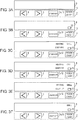
- FIG. 3A is a diagram illustrating a display state of display unit 8 before power is turned on.
- FIG. 3B is a diagram illustrating a display state of display unit 8 when power is turned on.
- FIG. 3C is a diagram illustrating a display state of display unit 8 in which, by operating the first switch in a state in which any heating menu item is not selected, "heating" is selected.
- FIG. 3D is a diagram illustrating a display state of display unit 8 in which, by operating the second switch in a state in which any heating menu item is not selected, "deep-fry" is selected.
- FIG. 3A is a diagram illustrating a display state of display unit 8 before power is turned on.
- FIG. 3B is a diagram illustrating a display state of display unit 8 when power is turned on.
- FIG. 3C is a diagram illustrating a display state of display unit 8 in which, by operating the first switch in a state in which any heating menu item is not selected, "heating" is selected.
- FIG. 3E is a diagram illustrating a display state of display unit 8 in which, by operating the first switch or the second switch in a state in which any heating menu item is not selected, "grill" is selected.
- FIG. 3F is a diagram illustrating a display state of display unit 8 when "grill" is finally set as a heating menu item.
- a user places object to be heated 1 at heating unit 11 on top plate 2 as illustrated in FIG. 1 and FIG. 2 .
- the user operates power switch 10 disposed in operation unit 7.
- electric power is supplied to each of the switches disposed in operation unit 7 and supplied to display unit 8. This leads to a state in which the user can set, for example, a heating menu item and heating conditions for object to be heated 1 via operation unit 7.
- control unit 9 turns on power indication light 13 disposed in display unit 8 to inform the user that power switch 10 is on, as illustrated in FIG. 3B .
- a heating menu item for heating object to be heated 1 placed on top plate 2 has not been set.
- control unit 9 automatically sets first switch 5 and second switch 6 as switches for selecting a heating menu item for heating object to be heated 1.
- control unit 9 causes display unit 8 to display all or some of heating menu items selectable by first switch 5 and second switch 6. Furthermore, control unit 9 sequentially causes heating menu items sequentially selected by a user's pressing operation to flash on and off. This flashing allows the user to recognize which heating menu item is in a state of being selected.
- control unit 9 causes display unit 8 to display all the preset heating menu items, namely, "heating", “grill”, and "deep-fry”. Then, control unit 9 causes the display of "heating" in display unit 8, selected by the user, to flash on and off.
- control unit 9 causes display unit 8 to display all the preset heating menu items, namely, "heating”, “grill”, and "deep-fry”. Then, control unit 9 causes the display of "deep-fry” in display unit 8, selected by the user, to flash on and off.
- a description is given by taking as an example a method of identification of a heating menu item selected by a user by causing the item to flash on and off, but a method of identification is not limited to this.
- a configuration for identifying a heating menu item may be such that a heating menu item selected by a user is displayed at a higher brightness than that of a heating menu item not selected by the user.
- a configuration may be such that a heating menu item selected by a user is displayed in a different manner from a heating menu item not selected by the user. That is, any identification method may be employed as long as the method enables a selected heating menu item to be identified.
- control unit 9 causes the shifted heating menu item to flash on and off in display unit 8.
- control unit 9 causes the display of "heating” to stop flashing on and off and causes the display of "grill” in display unit 8 to flash on and off.
- control unit 9 causes the display of "grill” to stop flashing on and off and causes the display of "deep-fry” in display unit 8 to flash on and off.
- control unit 9 causes the display of "deep-fry” to stop flashing on and off and causes the display of "heating" in display unit 8 to flash on and off.
- the induction heating cooker according to the present embodiment is configured such that, every time first switch 5 is operated, a plurality of the heating menu items is shifted in a single direction and selected sequentially.
- the induction heating cooker is configured such that, every time second switch 6 is operated, the plurality of the heating menu items is shifted in the opposite direction to that in the operation of first switch 5 and selected sequentially.
- menu item J is selected by a shift from menu item B, for example, when the selection is made in a clockwise direction by first switch 5, the selection needs eight operations. However, when the selection is made in a counter-clockwise direction by second switch 6, menu item J can be selected in two operations.
- second switch 6 in a state in which menu item F is selected, thereby making a counter-clockwise return to the previous heating menu item to select menu item E.
- second switch 6 allows the return to menu item E, whereby the target heating menu item is selected.
- control unit 9 starts heating object to be heated 1 by a heating operation corresponding to the set heating menu item.
- control unit 9 causes display unit 8 to display only the heating menu item set by the user with the item flashing on and off. With this, the user is informed of which heating menu item the user has set.
- control unit 9 automatically changes functions of first switch 5 and second switch 6 to the following functions in accordance with the heating menu item set by a user.
- control unit 9 causes display unit 8 to display information on a heating power for heating object to be heated 1. Furthermore, control unit 9 sets first switch 5 as a switch for increasing a heating power, and sets second switch 6 as a switch for decreasing a heating power. Then, in accordance with the operation of first switch 5 or second switch 6, control unit 9 controls a high frequency current to be supplied to heating coil 4 so as to increase or decrease a heating power for heating object to be heated 1.
- control unit 9 causes display unit 8 to display a target temperature for heating object to be heated 1. Furthermore, control unit 9 sets first switch 5 as a switch for increasing a target temperature for object to be heated 1, and sets second switch 6 as a switch for decreasing a target temperature for object to be heated 1. Then, in accordance with the operation of first switch 5 or second switch 6, control unit 9 controls a high frequency current to be supplied to heating coil 4 so as to increase or decrease the target temperature for object to be heated 1.
- first switch 5 and second switch 6 are set again in accordance with a heating menu item set by a user and a set state.
- the setting is such that the operation of first switch 5 causes a set value to change to be larger.
- the setting is such that the operation of second switch 6 causes a set value to change to be smaller.
- the directions of change in set values of first switch 5 and second switch 6 may be opposite to the above-mentioned directions.
- control unit 9 sets first switch 5 and second switch 6 as switches for selecting a heating menu item.
- control unit 9 sets first switch 5 and second switch 6 as switches for selecting a heating menu item.
- another switch for setting first switch 5 and second switch 6 as switches for selecting a heating menu item can be selected by first switch 5 and second switch 6.
- a predetermined heating menu item is selected from a plurality of heating menu items.
- it is configured such that the sequence of heating menu items selected one by one every operation of first switch 5 is the reverse of the sequence of heating menu items selected one by one every operation of second switch 6. Therefore, even in the case where there are many heating menu items, this configuration allows a larger reduction in the number of times of operation of first switch 5 or second switch 6 before a heating menu item is selected, compared with a configuration in which a heating menu item is selected by a single switch. Thus, the usability of induction heating cooker 100 is improved.
- first switch 5 or second switch 6 is pressed the wrong number of times past a heating menu item desired to be selected, the operation of the other switch for making the selection in an opposite direction to the operated switch allows a return to the heating menu item.
- a heating menu desired to be selected can be selected by a smaller number of times of operation. As a result, the operability of induction heating cooker 100 is improved.
- control unit 9 is configured to, when a heating menu item for heating object to be heated 1 is set, change the functions of first switch 5 and second switch 6 in accordance with the heating menu item set by a user and a set state. Hence, there is no need to dispose, in operation unit 7, a plurality of switches each for a corresponding one of functions. In other words, control unit 9 can change a set value for each of the functions of first switch 5 and second switch 6. This allows the configuration of operation unit 7 to be simplified, whereby the operability of induction heating cooker 100 is improved.
- control unit 9 is configured to, when a heating menu item for heating object to be heated 1 is set, set first switch 5 as a switch for increasing a heating power and set second switch 6 as a switch for decreasing a heating power.
- control unit 9 there is no need to dispose, in operation unit 7, another switch for setting first switch 5 and second switch 6 so as to function as switches for increasing and decreasing a heating power, respectively. That is, a heating power for heating object to be heated 1 can be increased and decreased only by first switch 5 and second switch 6, respectively.
- This allows the configuration of operation unit 7 to be simplified, whereby induction heating cooker 100 having excellent operability can be achieved.
- control unit 9 automatically causes first switch 5 and second switch 6 to operate as switches for selecting a heating menu item
- the present invention is not limited to this configuration. Any configuration may be employed as long as the configuration causes first switch 5 and second switch 6 to, in a state in which any heating menu item is not set, operate as switches for selecting a heating menu item.
- it may be configured such that, when a user operates any one of a plurality of switches disposed in operation unit 7, control unit 9 automatically causes first switch 5 and second switch 6 to operate as switches for selecting a heating menu item.
- the above-mentioned one switch is any one of first switch 5, second switch 6, and start switch 12, for example.
- Embodiment 2 of the present invention will be described using FIG. 4 .
- the same or equivalent constituents as those in the above-mentioned Embodiment 1 are assigned with the same reference numerals, and a duplicate description thereof will be omitted.
- FIG. 4 is a flowchart illustrating the selection of a heating menu item in Embodiment 2.
- the induction heating cooker according to the present embodiment is configured such that, first, when first switch 5 or second switch 6 is operated in a state in which any heating menu item for heating object to be heated 1 is not set, a preset first heating menu item is selected. Furthermore, the induction heating cooker is configured such that, when first switch 5 or second switch 6 is operated in a state in which the first heating menu item is set, a heating menu item different depending on the operated switch is selected. In terms of the above-mentioned configuration, the induction heating cooker according to the present embodiment differs from the induction heating cooker according to Embodiment 1.
- control unit 9 detects whether or not power switch 10 has been operated (step S101). If power switch 10 has not been operated (NO at step S101), the power source of induction heating cooker 100 is operated so that induction heating cooker 100 is put on standby until the operation of power switch 10 is detected.
- control unit 9 determines whether or not first switch 5 or second switch 6 has been operated (step S102). That is, if a user operates power switch 10 to turn on induction heating cooker 100 (YES at step S101), control unit 9 detects whether or not first switch 5 or second switch 6 has been operated (step S102).
- the present embodiment it is configured such that, when a user operates first switch 5 or second switch 6 in a state in which induction heating cooker 100 is turned on and any heating menu item is not set, regardless of which switch is operated, the same first heating menu item is selected.
- control unit 9 detects that first switch 5 or second switch 6 has not been operated (NO at step S102)
- the process returns to step S102. Then, induction heating cooker 100 is put on standby until first switch 5 or second switch 6 is operated.
- heating which is a frequently-used heating menu item, is set as a first heating menu item.
- any heating menu item may be set as a second or third heating menu item as long as a second heating menu item and a third heating menu item are different from each other.
- a second heating menu item and a third heating menu item there may be set arbitrary heating menu items selected from a plurality of heating menu items preset in induction heating cooker 100, heating menu items determined by a questionnaire survey addressed to users, and heating menu items intended to appeal to users.
- a plurality of heating menu items is disposed in a predetermined sequence.
- the direction of selection of a heating menu item by the operation of first switch 5 is configured to be different from (opposite to) the direction of selection of a heating menu item by the operation of second switch 6. That is, an improvement in the sequence or direction of selection of a heating menu item leads to a further improvement in the operability of induction heating cooker 100.
- the induction heating cooker according to the present embodiment is configured such that, when first switch 5 is operated in a state in which the first heating menu item is selected, a preset second heating menu item is selected. Furthermore, the induction heating cooker is configured such that, when second switch 6 is operated in a state in which the first heating menu item is selected, a preset third heating menu item is selected. That is, the induction heating cooker is configured such that, when first switch 5 or second switch 6 is operated after the first heating menu item is selected, a heating menu item different from the first heating menu item can be selected in accordance with the operated switch. Therefore, the number of times of operation of first switch 5 or second switch 6 before a user selects a heating menu item desired to be selected can be reduced. Thus, the operability of the induction heating cooker is improved.
- first display 14 may be in an arbitrary form as long as the form allows a user to recognize that first switch 5 and second switch 6 are switches for selecting a heating menu item.
- the display may be made by enclosing characters such as "menu" with a figure such as a square as illustrated in FIG. 5 .
- the display may be composed only of characters such as "menu”.
- the form of first display 14 is not limited to a particular form as long as the form is recognizable by a user. With this, a user can easily recognize that first switch 5 and second switch 6 are in an operating state as switches for selecting a heating menu item. Thus, the user can easily identify the operating state of first switch 5 and second switch 6. As a result, the usability of induction heating cooker 100 is improved.
- first switch 5 and second switch 6 function as not switches for selecting a heating menu item, but switches for operating other functions
- first display 14 is preferably not displayed. This prevents a user from misunderstanding the functions of first switch 5 and second switch 6. As a result, an unnecessary operation caused by the misunderstanding is prevented, and the usability of the induction heating cooker is further improved.
- FIG. 6 is a schematic diagram of the display unit, the diagram illustrating a state in which a modification of first display 14 according to Embodiment 4 is displayed.
- control unit 9 causes display unit 8 to display, via first display 14, that first switch 5 and second switch 6 are in an operating state as switches for selecting a heating menu item, and thereby to inform a user of the state.
- first display 14 is disposed such that at least part of first display 14 is positioned in the range of the left-right width between first switch 5 and second switch 6, both inclusive, illustrated in FIG. 6 .
- first display 14 is composed of a combination of two inverted triangles and characters such as "menu" disposed between the two inverted triangles.
- first display 14 is displayed in display unit 8 such that each of the apexes of the two inverted triangles is positioned at the top of a corresponding one of first switch 5 and second switch 6. This allows a user to appropriately recognize the correspondence.
- the induction heating cooker includes a main body including a top plate on which an object to be heated is placed, and a heating coil disposed inside the main body and configured to induction-heat the object to be heated placed on the top plate.
- the induction heating cooker further includes an operation unit configured to set a heating condition for heating the object to be heated placed on the top plate, a display unit configured to display the heating condition set by the operation unit, and a control unit configured to control a high frequency current to be supplied to the heating coil, in accordance with the heating condition set by the operation unit.
- control unit is configured to, when a heating menu item is set (determined), set the first switch as a switch for increasing a heating power for heating an object to be heated placed on the top plate and set the second switch as a switch for decreasing a heating power for heating an object to be heated placed on the top plate.
- the control unit sets the first switch and the second switch as switches for selecting a heating menu item. Therefore, it is not necessary to dispose, in the operation unit, another switch for setting the first switch and the second switch as switches for selecting a heating menu item for an object to be heated. With this, a heating menu item for heating an object to be heated can be quickly selected by the first switch and the second switch. As a result, an induction heating cooker having a simplified operation unit and providing usability is achieved.
- a heating menu desired to be selected can be selected by a smaller number of times of operation. As a result, usability is improved.
- control unit is configured to, when a heating menu item for heating an object to be heated placed on the top plate is set, set the first switch as a switch for increasing a heating power for heating an object to be heated.
- the control unit sets the second switch as a switch for decreasing a heating power for heating an object to be heated. Therefore, it is not necessary to dispose, in the operation unit, another switch for switching the first switch and the second switch to switches for increasing and decreasing a heating power for heating an object to be heated, respectively. That is, the control unit is capable of setting the first switch and the second switch as switches for increasing and decreasing a heating power for heating an object to be heated, respectively. This allows the configuration of the operation unit to be simplified, whereby an induction heating cooker providing usability is achieved.
- the induction heating cooker according to the present invention may be configured such that, when the first switch or the second switch is operated in a state in which any heating menu item is not set, a preset first heating menu item is selected.
- This configuration allows, for example, a highly-frequently-used heating menu item to be preset as the first heating menu item out of a plurality of heating menu items.
- a highly-frequently-used heating menu item can be selected by the first operation of the first switch or the second switch.
- the usability of the induction heating cooker is improved.
- the induction heating cooker according to the present invention may be configured such that, when the first switch is operated in a state in which the first heating menu item is selected, a preset second heating menu item is selected, and when the second switch is operated in a state in which the first heating menu item is selected, a preset third heating menu item is selected.
- the induction heating cooker according to the present invention may be configured such that the first switch and the second switch are disposed to adjacent to each other, and when the first switch and the second switch are in an operating state as switches for selecting a heating menu item, the display unit displays a first display for informing that a heating menu item is selectable by the first switch and the second switch.
- the induction heating cooker according to the present invention may be configured such that the first display is disposed at a position of the display unit, the position corresponding to the first switch and the second switch disposed to adjacent to each other.
- the induction heating cooker according to the present invention may be configured such that the first display is displayed so as to have at least part of the first display disposed at a position corresponding to the range of the left-right width between the first switch and the second switch, both inclusive.
- an expression for prompting the operation of the switches can be made with a "figure”
- an expression for indicating that the first switch and the second switch have been set as switches for selecting a heating menu item can be made with a "character”.
- a state in which the first switch and the second switch are operable can be expressed in various ways. With this, the user can more easily identify that the first switch and the second switch are in an operating state as switches for selecting a heating menu item. As a result, the usability of the induction heating cooker is further improved.
- the induction heating cooker according to the present invention may be configured such that, with a combination of a plurality of figures and a character disposed between the figures, the first display displays a state in which the first switch and the second switch are in an operable state.
Landscapes
- Physics & Mathematics (AREA)
- Electromagnetism (AREA)
- Induction Heating Cooking Devices (AREA)
Description
- The present invention relates to an induction heating cooker.
- Japanese Patent Unexamined Publication No.
2008-218103 Patent Literature 1") proposes a conventional induction heating cooker having a configuration in which a plurality of switches disposed in an operation unit includes at least one switch assigned with a plurality of control commands. This configuration allows the number of switches disposed in a top plate to be reduced without a reduction in the number of control commands. - Hereinafter, the conventional induction heating cooker proposed in
Patent Literature 1 will be described usingFIG. 7 . - As illustrated in
FIG. 7 , the conventional induction heating cooker includestop plate 201, a heating coil,operation unit 202, and a control unit.Top plate 201 is for placing a cooking container thereon. The heating coil is configured to generate an induction field, thereby induction-heating the cooking container.Operation unit 202 includes a plurality of switches assigned with their respective control commands. When such a switch ofoperation unit 202 is pressed, the control unit controls a high frequency current to be supplied to the heating coil, based on an inputted control command corresponding to the pressed switch. - Specifically,
switches operation unit 202.Switch 202b is assigned with two control commands, that is, a control command to set/release a lock for enabling/disabling an operation and a control command to select cooking menu items, namely, deep-frying, water-boiling, and rice-cooking.Switch 202a corresponds to a heating on/off switch for controlling turn-on/off of heating. Switch 202c andswitch 202d correspond to adjustment switches for increasing/decreasing a heating power and adjusting temperature. Switch 202e corresponds to a timer switch for setting a heating time. - The conventional induction heating cooker is normally locked in a state of being turned on an electric power supply so as to disable the operation of
switches switch 202b is assigned with a control command to unlockswitches switch 202b is pressed in a state in which switches 202a, 202c, 202d, and 202e are locked,switches - Furthermore, when
switch 202e serving as a timer switch is pressed in a state in which switches 202a, 202c, 202d, and 202e are unlocked,switch 202b is switched to function as a menu switch assigned with a control command to select a cooking menu item. In other words,switch 202b is configured that, everytime switch 202b is pressed, a cooking menu item is sequentially selected from modes of "deep-fry", "water-boiling", and "rice-cooking". - Furthermore, the induction heating cooker is configured so that, when
switch 202a serving as a heating on/off switch is pressed in a state in which a predetermined cooking menu item is selected by the operation ofswitch 202b, heating is initiated in accordance with the selected predetermined cooking menu item. - The above-mentioned induction heating cooker is configured so that heating menu items are sequentially selected in a single direction in accordance with the number of times of operation of a single switch for selecting a cooking menu item. Here, in the case where there are many heating menu items to be selected, or in the case where a heating menu item desired to be selected is in the latter half of the sequence, a user needs to operate the switch two or more times. This causes an increase in the number of times of operations for selecting a cooking menu item, and thereby sometimes impairs the usability.
- Furthermore, at the time of selecting a cooking menu item, sometimes the switch is pressed the wrong number of times past a heating menu item desired to be selected. In this case, in order to make a return to the heating menu item desired to be selected, the user needs to operate the switch for selecting a cooking menu item further two or more times to make a round to the heating menu item. Alternatively, the user needs to stop halfway the operation for selecting the heating menu item and try again the selection of the heating menu item from the beginning. This impairs usability in the selection of a cooking menu item.
- Besides a switch for at least selecting a cooking menu item, the conventional induction heating cooker needs to be provided with another switch (for example,
switch 202e) for making valid a control command to select a cooking menu item from a plurality of control commands. This makes the configuration of the operation unit more complicated. - Therefore, in order to improve the usability of induction heating cookers, an induction heating cooker having the following configurations has been proposed.
- Specifically, the above-mentioned induction heating cooker includes three switches. A first switch is a switch assigned with a control command to increase a heating power for heating an object to be heated placed on a top plate and a control command to select a cooking menu item. A second switch is a switch assigned with a control command to decrease a heating power for heating an object to be heated placed on the top plate and a control command to select a cooking menu item. A third switch is a switch for switching between a control command to increase or decrease a heating power and a control command to select a cooking menu item. When the third switch for switching between the control commands is operated, the control command to select a cooking menu item becomes valid. With this configuration, a cooking menu item can be selected by the first switch for increasing a heating power or the second switch for decreasing a heating power.
- In other words, the above-mentioned induction heating cooker is configured to sequentially select a plurality of cooking menu items in different directions in accordance with the operation of the first switch for increasing a heating power and the second switch for decreasing a heating power.
- However, even in the above-mentioned induction heating cooker, there is yet room for improvement in the simplification of the operation unit and usability.
- That is, besides the switch assigned with a control command to increase or decrease a heating power and a control command to select a cooking menu item, the above-mentioned induction heating cooker needs to be provided with a switch for making valid a control command to select a cooking menu item from a plurality of control commands. Accordingly, the configuration of the operation unit becomes more complicated. This impairs the usability of the induction heating cooker.
-
EP 2 065 651 A2 -
WO 2011/128293 A2 describes a programmable user interaction control interface for household appliances such as ovens. The user interface comprises a display for displaying text and icons. The user interface further comprises control and selection buttons for navigation in a two dimensional menu structure. LED technology is used in order to lit up buttons as well as indicators. -
EP 2 161 966 A1 describes an induction heating device which includes an infrared ray sensor for detecting infrared rays radiated from a cooking container through a top plate, a light emitting device which is placed near the infrared ray sensor and emits light to the back surface of the top plate, and aheating control unit 8 which controls a high-frequency current through a heating coil for controlling the heating of the cooking container. When the heating control unit has stopped the heating of the cooking container, and a predetermined time elapses at the heating-stopped state, the light emitting device is controlled to stop the light emission therefrom. This can improve durability of the light emitting device, which enables maintaining a function of clearly indicating a position at which the cooking container should be placed and a function of detecting failures in the infrared ray sensor, which are roles of the light emitting device. - The invention is defined by the subject-matter of
independent claim 1. The dependent claims are directed to advantageous embodiments. - The present invention provides an induction heating cooker having a simplified operation unit and providing usability.
- That is, the induction heating cooker according to the present invention includes a main body including a top plate on which an object to be heated is placed, and a heating coil disposed inside the main body and configured to induction-heat the object to be heated placed on the top plate. The induction heating cooker further includes an operation unit configured to set a heating condition for heating an object to be heated placed on the top plate, a display unit configured to display the heating condition set by the operation unit, and a control unit configured to control a high frequency current to be supplied to the heating coil, in accordance with the heating condition set by the operation unit. The operation unit includes a first switch configured to operate as a switch for selecting a heating menu item for heating an object to be heated placed on the top plate from a plurality of preset heating menu items and as a switch for increasing a heating power for heating an object to be heated placed on the top plate. The operation unit further includes a second switch configured to operate as a switch for selecting a heating menu item for heating an object to be heated placed on the top plate from a plurality of preset heating menu items and as a switch for decreasing a heating power for heating an object to be heated placed on the top plate. The control unit is configured to, when any heating menu item has not been set, set the first switch and the second switch as switches for selecting a heating menu item for heating an object to be heated placed on the top plate. Furthermore, the control unit is configured to, when a heating menu item is set, set the first switch as a switch for increasing a heating power for heating an object to be heated placed on the top plate and set the second switch as a switch for decreasing a heating power for heating an object to be heated placed on the top plate.
- With this configuration, when any heating menu item for heating an object to be heated has not been set, the control unit sets the first switch and the second switch as switches for selecting a heating menu item. Therefore, it is not necessary to dispose, in the operation unit, another switch for setting the first switch and the second switch as switches for selecting a heating menu item for an object to be heated. With this, a heating menu item for heating an object to be heated can be quickly selected by the first switch and the second switch. As a result, an induction heating cooker having a simplified operation unit and providing usability is achieved.
- A user can select a predetermined heating menu item from a plurality of heating menu items by operating the two switches, namely, the first switch and the second switch. Accordingly, for example, it can be configured such that the sequence of heating menu items selected one by one every operation of the first switch is the reverse of the sequence of heating menu items selected one by one every operation of the second switch. Thus, even in the case where there are many preset heating menu items, this configuration allows a larger reduction in the number of times of operation of the first switch or the second switch before a heating menu item is selected, compared with a configuration in which a heating menu item is selected with a single switch from a plurality of heating menu items. As a result, the usability of the induction heating cooker is improved.
- Furthermore, even when a user presses the first switch or the second switch the wrong number of times past a heating menu item desired to be selected, the selection of a heating menu item can be reversed by the operation of the other switch for making the selection in an opposite direction to the wrongly-operated switch. With this, a heating menu desired to be selected can be selected by a smaller number of times of operation. As a result, usability is improved.
- Furthermore, the control unit is configured to, when a heating menu item for heating an object to be heated placed on the top plate is set, set the first switch as a switch for increasing a heating power for heating an object to be heated. At the same time, the control unit sets the second switch as a switch for decreasing a heating power for heating an object to be heated. Therefore, it is not necessary to dispose, in the operation unit, another switch for switching the first switch and the second switch to switches for increasing and decreasing a heating power for heating an object to be heated, respectively. That is, the control unit is capable of setting the first switch and the second switch as switches for increasing and decreasing a heating power for heating an object to be heated, respectively. This allows the configuration of the operation unit to be simplified, whereby an induction heating cooker providing usability is achieved.
-
-
FIG. 1 is a schematic diagram of an induction heating cooker according toEmbodiment 1 of the present invention. -
FIG. 2 is a top view of a top plate according toEmbodiment 1. -
FIG. 3A is a diagram illustrating a display state of a display unit inEmbodiment 1 before power is turned on. -
FIG. 3B is a diagram illustrating a display state of the display unit inEmbodiment 1 when power is turned on. -
FIG. 3C is a diagram illustrating a display state of the display unit inEmbodiment 1, in which, by operating the first switch in a state in which any heating menu item is not selected, "heating" is selected. -
FIG. 3D is a diagram illustrating a display state of the display unit inEmbodiment 1, in which, by operating the second switch in a state in which any heating menu item is not selected, "deep-fry" is selected. -
FIG. 3E is a diagram illustrating a display state of the display unit inEmbodiment 1, in which, by operating the first switch or the second switch in a state in which any heating menu item is not selected, "grill" is selected. -
FIG. 3F is a diagram illustrating a display state of the display unit inEmbodiment 1 when "grill" is set as a heating menu item. -
FIG. 4 is a flowchart illustrating the selection of heating menu items inEmbodiment 2 of the present invention. -
FIG. 5 is a schematic diagram of the display unit, the diagram illustrating a state in which a first display according toEmbodiment 3 of the present invention is displayed. -
FIG. 6 is a schematic diagram of the display unit, the diagram illustrating a state in which a modification of the first display according toEmbodiment 4 of the present invention is displayed. -
FIG. 7 is a top view of a top plate of a conventional induction heating cooker. - Hereinafter, preferred embodiments of an induction heating cooker of the present invention will be described in detail with reference to the drawings. It should be noted that, in the following description, the same or equivalent constituents are assigned with the same reference numerals, and a duplicate description thereof will be omitted.
- Hereinafter, an induction heating cooker according to
Embodiment 1 of the present invention will be described usingFIG. 1 andFIG. 2 . -
FIG. 1 is a schematic diagram of the induction heating cooker according to the present embodiment.FIG. 2 is a top view of a top plate according to the present embodiment. - As illustrated in
FIG. 1 ,induction heating cooker 100 according to the present embodiment includesmain body 3 includingtop plate 2 for placing object to be heated 1 thereon,heating coil 4 disposed insidemain body 3,operation unit 7,display unit 8, andcontrol unit 9.Heating coil 4 is configured to induction-heating object to be heated 1, such as a pan, which is placed ontop plate 2.Operation unit 7 is configured to set a heating condition for object to be heated 1.Display unit 8 is configured to display, for example, the heating condition set byoperation unit 7.Control unit 9 is configured to control, for example, a high frequency current to be supplied toheating coil 4 in accordance with the heating condition set byoperation unit 7. -
Operation unit 7 anddisplay unit 8 are disposed at the front portion of the top plate as illustrated inFIG. 2 . - It should be noted that, in the following description, as illustrated in
FIG. 2 , wheninduction heating cooker 100 is disposed at a kitchen counter or the like, a side closer to a user and the other side are denoted by the "front" and the "back", respectively; and the left side and the right side when viewed from the front are denoted by the "left" and the "right", respectively. - As illustrated in
FIG. 2 , a plurality (three in the present embodiment) ofheating units 11 indicating positions to place object to be heated 1 thereat is formed on the top face oftop plate 2. Under each of the plurality ofheating units 11, a corresponding one ofheating coils 4 is disposed. -
Operation unit 7 includespower switch 10,first switch 5,second switch 6, and startswitch 12. - When pressed by a user, each of the switches functions as follows.
-
Power switch 10 causesinduction heating cooker 100 to be turned on. -
First switch 5 operates as a switch for selecting, in a single direction, a heating menu item for heating object to be heated 1 placed ontop plate 2 from a plurality of preset heating menu items. Furthermore,first switch 5 operates as a switch for increasing a heating power for heating object to be heated 1. Likewise,second switch 6 operates as a switch for selecting, in the reverse direction, a heating menu item for heating object to be heated 1 placed ontop plate 2 from a plurality of preset heating menu items. In other words,second switch 6 is configured to select a heating menu item in an opposite (return) direction to that offirst switch 5. Furthermore,second switch 6 operates as a switch for decreasing a heating power for heating object to be heated 1. - Start
switch 12 determines a heating menu item and a heating power selected byfirst switch 5 andsecond switch 6, and sets the heating menu item and the heating power incontrol unit 9 as heating conditions for heating object to be heated 1. That is, startswitch 12 is used also asdetermination switch 7a.Determination switch 7a determines a selected heating menu item. - It should be noted that
first switch 5,second switch 6, and start switch 12 (determination switch 7a) are disposed in each ofheating units 11 formed intop plate 2. -
Display unit 8 is disposed at the back ofoperation unit 7, and displays, for example, heating menu items selected byfirst switch 5 andsecond switch 6. Furthermore, besides a heating menu item,display unit 8 displays heating conditions set byoperation unit 7. For example,display unit 8 displays the level of heat for heating object to be heated 1 and a remaining time of a timer having a function of stopping heating after a lapse of a predetermined time period. - It should be noted that, in the present embodiment, as heating menu items selected by
first switch 5 andsecond switch 6, for example, "heating", "deep-fry", "grill", and "water-boiling" are preset. -
Control unit 9 controls a high frequency current to be supplied toheating coil 4, based on information, such as a heating power set byfirst switch 5 andsecond switch 6, the temperature of object to be heated 1, and the time elapsed since the start of heating. Here, in accordance with a control method preset so as to correspond to a heating menu item,control unit 9 controls a high frequency current to be supplied toheating coil 4. -
Induction heating cooker 100 according to the present embodiment is configured as described above. - Hereinafter, with reference to
FIG. 1 andFIG. 2 , the operation and functions ofinduction heating cooker 100 having the above-mentioned configuration will be described usingFIG. 3A to FIG. 3F . - It should be noted that, hereinafter, a configuration example will be described in which "heating", "grill", and "deep-fry" are preset as heating menu items in
induction heating cooker 100. Specifically, "heating" is to heat object to be heated 1. "Grill" is to heat object to be heated 1, thereby grilling a food material accommodated in object to be heated 1. "Deep-fry" is to heat object to be heated 1, thereby frying a food material in a large amount of oil accommodated in object to be heated 1. -
FIG. 3A is a diagram illustrating a display state ofdisplay unit 8 before power is turned on.FIG. 3B is a diagram illustrating a display state ofdisplay unit 8 when power is turned on.FIG. 3C is a diagram illustrating a display state ofdisplay unit 8 in which, by operating the first switch in a state in which any heating menu item is not selected, "heating" is selected.FIG. 3D is a diagram illustrating a display state ofdisplay unit 8 in which, by operating the second switch in a state in which any heating menu item is not selected, "deep-fry" is selected.FIG. 3E is a diagram illustrating a display state ofdisplay unit 8 in which, by operating the first switch or the second switch in a state in which any heating menu item is not selected, "grill" is selected.FIG. 3F is a diagram illustrating a display state ofdisplay unit 8 when "grill" is finally set as a heating menu item. - First, a user places object to be heated 1 at
heating unit 11 ontop plate 2 as illustrated inFIG. 1 andFIG. 2 . Then, the user operatespower switch 10 disposed inoperation unit 7. With this operation, electric power is supplied to each of the switches disposed inoperation unit 7 and supplied to displayunit 8. This leads to a state in which the user can set, for example, a heating menu item and heating conditions for object to be heated 1 viaoperation unit 7. - Specifically, in a state in which
power switch 10 is not operated as illustrated inFIG. 3A , a user operatespower switch 10. With this operation,control unit 9 turns onpower indication light 13 disposed indisplay unit 8 to inform the user thatpower switch 10 is on, as illustrated inFIG. 3B . At this time, a heating menu item for heating object to be heated 1 placed ontop plate 2 has not been set. - Then, when the user turns on
power switch 10,control unit 9 automatically setsfirst switch 5 andsecond switch 6 as switches for selecting a heating menu item for heating object to be heated 1. - Next, when the user operates
first switch 5 orsecond switch 6, one heating menu item is selected from a plurality of preset heating menu items. At this time,control unit 9 causesdisplay unit 8 to display all or some of heating menu items selectable byfirst switch 5 andsecond switch 6. Furthermore,control unit 9 sequentially causes heating menu items sequentially selected by a user's pressing operation to flash on and off. This flashing allows the user to recognize which heating menu item is in a state of being selected. - Specifically, as illustrated in
FIG. 3C , when a user operatesfirst switch 5 in a state in which any heating menu item is not set, "heating" is selected from a plurality of heating menu items preset ininduction heating cooker 100. At this time,control unit 9 causesdisplay unit 8 to display all the preset heating menu items, namely, "heating", "grill", and "deep-fry". Then, controlunit 9 causes the display of "heating" indisplay unit 8, selected by the user, to flash on and off. - By contrast, as illustrated in
FIG. 3D , when a user operatessecond switch 6 in a state in which any heating menu item is not set, "deep-fry" is selected from the plurality of the preset heating menu items. At this time,control unit 9 causesdisplay unit 8 to display all the preset heating menu items, namely, "heating", "grill", and "deep-fry". Then, controlunit 9 causes the display of "deep-fry" indisplay unit 8, selected by the user, to flash on and off. - It should be noted that, in the present embodiment, a description is given by taking as an example a method of identification of a heating menu item selected by a user by causing the item to flash on and off, but a method of identification is not limited to this. For example, a configuration for identifying a heating menu item may be such that a heating menu item selected by a user is displayed at a higher brightness than that of a heating menu item not selected by the user. Alternatively, a configuration may be such that a heating menu item selected by a user is displayed in a different manner from a heating menu item not selected by the user. That is, any identification method may be employed as long as the method enables a selected heating menu item to be identified.
- Next, when the user operates
first switch 5 orsecond switch 6 again in a state in which one heating menu item is selected, the item is sequentially shifted to the subsequent heating menu item in accordance with the operation offirst switch 5 orsecond switch 6. Then, controlunit 9 causes the shifted heating menu item to flash on and off indisplay unit 8. - Specifically, first, when a user operates
first switch 5 again in a state in which "heating" is selected by the operation offirst switch 5, the display is sifted to the subsequent display of "grill" as illustrated inFIG. 3E . At this time,control unit 9 causes the display of "heating" to stop flashing on and off and causes the display of "grill" indisplay unit 8 to flash on and off. With this operation, the user is informed that the heating menu item has been changed from "heating" to "grill". - Next, when the user operates
first switch 5 again in the state in which "grill" is selected, the display is shifted to the subsequent display of "deep-fry". At this time,control unit 9 causes the display of "grill" to stop flashing on and off and causes the display of "deep-fry" indisplay unit 8 to flash on and off. With this, the user is informed that the heating menu item has been changed from "grill" to "deep-fry". - Furthermore, when the user operates
first switch 5 again in the state in which "deep-fry" is selected, the display is shifted to the subsequent display of "heating". At this time,control unit 9 causes the display of "deep-fry" to stop flashing on and off and causes the display of "heating" indisplay unit 8 to flash on and off. With this, the user is informed that the heating menu item has been changed from "deep-fry" to "heating". - When a user operates
second switch 6 in a state in which "heating" is selected by the operation offirst switch 5, the display is sifted to the display of "deep-fry". At this time,control unit 9 causes the display of "heating" to stop flashing on and off and causes the display of "deep-fry" indisplay unit 8 to flash on and off again. With this, the user is informed that the heating menu item has been returned from "heating" to "deep-fry". - By contrast, as is the case with the operation of
first switch 5, when the user operatessecond switch 6 again in a state in which "deep-fry" is selected by the operation ofsecond switch 6, the display is sifted to the subsequent display of "grill". At this time,control unit 9 causes the display of "deep-fry" to stop flashing on and off and causes the display of "grill" indisplay unit 8 to flash on and off. With this, the user is informed that the heating menu item has been changed from "deep-fry" to "grill". - Next, when the user operates
second switch 6 again in the state in which "grill" is selected, the display is shifted to the subsequent display of "heating". At this time,control unit 9 causes the display of "grill" to stop flashing on and off and causes the display of "heating" indisplay unit 8 to flash on and off. With this operation, the user is informed that the heating menu item has been changed from "grill" to "heating". - Furthermore, when the user operates
second switch 6 again in the state in which "heating" is selected, the display is shifted to the subsequent display of "deep-fry". At this time,control unit 9 causes the display of "heating" to stop flashing on and off and causes the display of "deep-fry" indisplay unit 8 to flash on and off. With this, the user is informed that the heating menu item has been changed from "heating" to "deep-fry". - When a user operates
first switch 5 in a state in which "deep-fry" is selected by the operation ofsecond switch 6, the display is sifted to the display of "heating". At this time,control unit 9 causes the display of "deep-fry" to stop flashing on and off and causes the display of "heating" indisplay unit 8 to flash on and off again. With this, the user is informed that the heating menu item has been returned from "deep-fry" to "heating". - That is, the induction heating cooker according to the present embodiment is configured such that, every time
first switch 5 is operated, a plurality of the heating menu items is shifted in a single direction and selected sequentially. By contrast, the induction heating cooker is configured such that, every timesecond switch 6 is operated, the plurality of the heating menu items is shifted in the opposite direction to that in the operation offirst switch 5 and selected sequentially. - Hereinafter, a specific selection operation will be described by taking as an example a case in which, for example, ten heating menu items (menu item A, menu item B, menu item C, menu item D, menu item E, menu item F, menu item G, menu item H, menu item I, and menu item J) are preset in
induction heating cooker 100 and the ten heating menu items are disposed in clockwise order and displayed indisplay unit 8. - For example, in the case where menu item J is selected by a shift from menu item B, for example, when the selection is made in a clockwise direction by
first switch 5, the selection needs eight operations. However, when the selection is made in a counter-clockwise direction bysecond switch 6, menu item J can be selected in two operations. - When a heating menu item E is selected by a shift from currently-selected menu item B, if a user makes a mistake in the number of times of operation and thereby press
first switch 5 four times, menu item F is selected past menu item E. In this case, menu item E can be selected by the following operation. - That is, the user operates
second switch 6 in a state in which menu item F is selected, thereby making a counter-clockwise return to the previous heating menu item to select menu item E. Thus, a single operation ofsecond switch 6 allows the return to menu item E, whereby the target heating menu item is selected. - As described above, a target heating menu item can be selected by a smaller number of times of operation of
first switch 5 andsecond switch 6 - Next, in a state in which one heating menu item is selected, a user operates start
switch 12 serving also asdetermination switch 7a. With this operation, the heating menu item selected byoperation unit 7 is determined, and set incontrol unit 9. Then, controlunit 9 starts heating object to be heated 1 by a heating operation corresponding to the set heating menu item. At this time,control unit 9 causesdisplay unit 8 to display only the heating menu item set by the user with the item flashing on and off. With this, the user is informed of which heating menu item the user has set. - Furthermore,
control unit 9 causesdisplay unit 8 to display information on a present heating state such as the level of heat and a target temperature, besides a heating menu item set by a user. - Specifically, a user operates start switch 12 (serving also as
determination switch 7a) in a state in which "grill" is selected by the operation offirst switch 5 orsecond switch 6. With this operation, "grill" is set incontrol unit 9 as a heating menu item for object to be heated 1. At this time, as illustrated inFIG. 3F ,control unit 9 causesdisplay unit 8 to display only "grill" set by the user out of "heating", "grill", and "deep-fry", which are displayed indisplay unit 8 at the time of the selection. At the same time,control unit 9 causes the display of "grill" indisplay unit 8 to flash on and off. - Next, when a heating menu item for object to be heated 1 is set,
control unit 9 automatically changes functions offirst switch 5 andsecond switch 6 to the following functions in accordance with the heating menu item set by a user. - For example, in the case where "heating" is set as a heating menu item,
control unit 9 causesdisplay unit 8 to display information on a heating power for heating object to be heated 1. Furthermore,control unit 9 setsfirst switch 5 as a switch for increasing a heating power, and setssecond switch 6 as a switch for decreasing a heating power. Then, in accordance with the operation offirst switch 5 orsecond switch 6,control unit 9 controls a high frequency current to be supplied toheating coil 4 so as to increase or decrease a heating power for heating object to be heated 1. - By contrast, in the case where "grill" or "deep-fry" is set as a heating menu item,
control unit 9 causesdisplay unit 8 to display a target temperature for heating object to be heated 1. Furthermore,control unit 9 setsfirst switch 5 as a switch for increasing a target temperature for object to be heated 1, and setssecond switch 6 as a switch for decreasing a target temperature for object to be heated 1. Then, in accordance with the operation offirst switch 5 orsecond switch 6,control unit 9 controls a high frequency current to be supplied toheating coil 4 so as to increase or decrease the target temperature for object to be heated 1. - It may be configured such that, for example, in the case where a timer switch (not illustrated) is operated during the execution of a heating menu item, a setting time of a timer can be increased or decreased by
first switch 5 orsecond switch 6. In this case,control unit 9 setsfirst switch 5 as a switch for increasing a setting time of a timer, and setssecond switch 6 as a switch for decreasing a setting time of a timer. Then, in accordance with the operation offirst switch 5 orsecond switch 6,control unit 9 exerts control to make a setting time of a timer longer or shorter. - In other words, in the present embodiment, it is configured such that functions of
first switch 5 andsecond switch 6 are set again in accordance with a heating menu item set by a user and a set state. For example, the setting is such that the operation offirst switch 5 causes a set value to change to be larger. On the other hand, the setting is such that the operation ofsecond switch 6 causes a set value to change to be smaller. It should be noted that the directions of change in set values offirst switch 5 andsecond switch 6 may be opposite to the above-mentioned directions. - As described above, in the present embodiment, when any heating menu item for heating object to be heated 1 has not been set,
control unit 9 setsfirst switch 5 andsecond switch 6 as switches for selecting a heating menu item. Hence, there is no need to dispose, inoperation unit 7, another switch for settingfirst switch 5 andsecond switch 6 as switches for selecting a heating menu item. That is, a heating menu item for heating object to be heated 1 can be selected byfirst switch 5 andsecond switch 6. This allows the configuration ofoperation unit 7 to be simplified, wherebyinduction heating cooker 100 providing usability can be achieved. - In the present embodiment, using two switches, namely,
first switch 5 andsecond switch 6, a predetermined heating menu item is selected from a plurality of heating menu items. At this time, it is configured such that the sequence of heating menu items selected one by one every operation offirst switch 5 is the reverse of the sequence of heating menu items selected one by one every operation ofsecond switch 6. Therefore, even in the case where there are many heating menu items, this configuration allows a larger reduction in the number of times of operation offirst switch 5 orsecond switch 6 before a heating menu item is selected, compared with a configuration in which a heating menu item is selected by a single switch. Thus, the usability ofinduction heating cooker 100 is improved. Furthermore, even whenfirst switch 5 orsecond switch 6 is pressed the wrong number of times past a heating menu item desired to be selected, the operation of the other switch for making the selection in an opposite direction to the operated switch allows a return to the heating menu item. With this, a heating menu desired to be selected can be selected by a smaller number of times of operation. As a result, the operability ofinduction heating cooker 100 is improved. - Furthermore, in the present embodiment,
control unit 9 is configured to, when a heating menu item for heating object to be heated 1 is set, change the functions offirst switch 5 andsecond switch 6 in accordance with the heating menu item set by a user and a set state. Hence, there is no need to dispose, inoperation unit 7, a plurality of switches each for a corresponding one of functions. In other words, controlunit 9 can change a set value for each of the functions offirst switch 5 andsecond switch 6. This allows the configuration ofoperation unit 7 to be simplified, whereby the operability ofinduction heating cooker 100 is improved. - In particular, in the present embodiment,
control unit 9 is configured to, when a heating menu item for heating object to be heated 1 is set, setfirst switch 5 as a switch for increasing a heating power and setsecond switch 6 as a switch for decreasing a heating power. Hence, there is no need to dispose, inoperation unit 7, another switch for settingfirst switch 5 andsecond switch 6 so as to function as switches for increasing and decreasing a heating power, respectively. That is, a heating power for heating object to be heated 1 can be increased and decreased only byfirst switch 5 andsecond switch 6, respectively. This allows the configuration ofoperation unit 7 to be simplified, wherebyinduction heating cooker 100 having excellent operability can be achieved. - It should be noted that, in the above-mentioned embodiment, a configuration example is described in which, when
power switch 10 is turned on,control unit 9 automatically causesfirst switch 5 andsecond switch 6 to operate as switches for selecting a heating menu item, but the present invention is not limited to this configuration. Any configuration may be employed as long as the configuration causesfirst switch 5 andsecond switch 6 to, in a state in which any heating menu item is not set, operate as switches for selecting a heating menu item. For example, it may be configured such that, when a user operates any one of a plurality of switches disposed inoperation unit 7,control unit 9 automatically causesfirst switch 5 andsecond switch 6 to operate as switches for selecting a heating menu item. Also with this configuration, the same effects as those in the above-mentioned embodiment are achieved. It should be noted that the above-mentioned one switch is any one offirst switch 5,second switch 6, and startswitch 12, for example. - Hereinafter, an induction heating cooker according to
Embodiment 2 of the present invention will be described usingFIG. 4 . It should be noted that the same or equivalent constituents as those in the above-mentionedEmbodiment 1 are assigned with the same reference numerals, and a duplicate description thereof will be omitted. -
FIG. 4 is a flowchart illustrating the selection of a heating menu item inEmbodiment 2. - The induction heating cooker according to the present embodiment is configured such that, first, when
first switch 5 orsecond switch 6 is operated in a state in which any heating menu item for heating object to be heated 1 is not set, a preset first heating menu item is selected. Furthermore, the induction heating cooker is configured such that, whenfirst switch 5 orsecond switch 6 is operated in a state in which the first heating menu item is set, a heating menu item different depending on the operated switch is selected. In terms of the above-mentioned configuration, the induction heating cooker according to the present embodiment differs from the induction heating cooker according toEmbodiment 1. - That is, as illustrated in
FIG. 4 , when object to be heated 1 is heated usinginduction heating cooker 100, first, a user operatespower switch 10 disposed inoperation unit 7. With this operation,power switch 10 ofinduction heating cooker 100 is turned on. - Then, first,
control unit 9 detects whether or notpower switch 10 has been operated (step S101). Ifpower switch 10 has not been operated (NO at step S101), the power source ofinduction heating cooker 100 is operated so thatinduction heating cooker 100 is put on standby until the operation ofpower switch 10 is detected. - On the other hand, if a user has operated power switch 10 (YES at step S101),
induction heating cooker 100 is turned on, wherebyinduction heating cooker 100 becomes operable. - Next,
control unit 9 determines whether or notfirst switch 5 orsecond switch 6 has been operated (step S102). That is, if a user operatespower switch 10 to turn on induction heating cooker 100 (YES at step S101),control unit 9 detects whether or notfirst switch 5 orsecond switch 6 has been operated (step S102). - If detecting the operation of
first switch 5 or second switch 6 (YES at step S102),control unit 9 selects a preset first heating menu item, for example, "heating" (step S103). - In other words, in the present embodiment, it is configured such that, when a user operates
first switch 5 orsecond switch 6 in a state in whichinduction heating cooker 100 is turned on and any heating menu item is not set, regardless of which switch is operated, the same first heating menu item is selected. - On the other hand, if
control unit 9 detects thatfirst switch 5 orsecond switch 6 has not been operated (NO at step S102), the process returns to step S102. Then,induction heating cooker 100 is put on standby untilfirst switch 5 orsecond switch 6 is operated. - Here, in the present embodiment, at the time of heating object to be heated 1, "heating", which is a frequently-used heating menu item, is set as a first heating menu item.
- It should be noted that, in the above-mentioned embodiment, a configuration example is described in which, when
first switch 5 orsecond switch 6 is operated in a state in which any heating menu item is not set, "heating" is selected as a first heating menu item, but the present invention is not limited to this configuration. In other words, any configuration may be employed as long as the configuration causesfirst switch 5 andsecond switch 6 to, in a state in which any heating menu item is not set, select a common heating menu item, whenfirst switch 5 orsecond switch 6 is operated. For example, a heating menu item intended to appeal to a user, or a highly-frequently-used heating menu item determined by, for example, a questionnaire survey addressed to users may be set as a first heating menu item. This allows the induction heating cooker to be customized to user's preference. - When "heating" serving as a first heating menu item is selected (step S103),
control unit 9 causesdisplay unit 8 to display all the heating menu items, namely, "heating", "grill", and "deep-fry", that have been preset ininduction heating cooker 100. At the same time,control unit 9 causes the display of "heating" indisplay unit 8 to flash on and off. With this operation, the user is informed that "heating" has been selected as the first heating menu item. - Next,
control unit 9 detects whether or notfirst switch 5 has been operated (step S104). If the operation offirst switch 5 is detected (YES at step 5104),control unit 9 selects, for example, "grill" as a second heating menu item (step S105). - On the other hand, if the operation of
first switch 5 is not detected (NO at step S104),control unit 9 detects whether or notsecond switch 6 has been operated (step S106). If the operation ofsecond switch 6 is detected (YES at step S106),control unit 9 selects, for example, "deep-fry" as a third heating menu item (step S107). - On the other hand, if the operation of
second switch 6 is not detected (NO at step S106),control unit 9 makes a return to step S104 for detecting again whether or notfirst switch 5 has been operated. Then, the operations at step S104 and the subsequent steps are executed in the same manner. - In other words, in the present embodiment, it is configured such that, when a user operates
first switch 5 orsecond switch 6 in a state in which a first heating menu item is selected, a heating menu item different from the first heating menu item is selected in accordance with the operated switch. - It should be noted that, in the above-mentioned embodiment, a configuration example is described in which "grill" and "deep-fry" are set as a second heating menu item and a third heating menu item, respectively, but the present invention is not limited to this configuration. In other words, any heating menu item may be set as a second or third heating menu item as long as a second heating menu item and a third heating menu item are different from each other. For example, as a second heating menu item and a third heating menu item, there may be set arbitrary heating menu items selected from a plurality of heating menu items preset in
induction heating cooker 100, heating menu items determined by a questionnaire survey addressed to users, and heating menu items intended to appeal to users. - Furthermore, in the present embodiment, a plurality of heating menu items is disposed in a predetermined sequence. Specifically, for example, at step S104 and step S106 illustrated in
FIG. 4 , the direction of selection of a heating menu item by the operation offirst switch 5 is configured to be different from (opposite to) the direction of selection of a heating menu item by the operation ofsecond switch 6. That is, an improvement in the sequence or direction of selection of a heating menu item leads to a further improvement in the operability ofinduction heating cooker 100. - Furthermore, in the present embodiment, at step S104 or step S106 illustrated in
FIG. 4 ,first switch 5 orsecond switch 6 is operated to select "grill" as the second heating menu item or "deep-fry" as the third heating menu item. At this time, in accordance with a heating menu item selected by a user,control unit 9 causes the display of "grill" or "deep-fry" indisplay unit 8 to flash on and off. With this, the user can be informed that "grill" or "deep-fry" has been selected as a heating menu item. - As described above, the induction heating cooker according to the present embodiment is configured such that, when
first switch 5 orsecond switch 6 is operated in a state in which any heating menu item is not set, a preset first heating menu item is selected. At this time, for example, as the first heating menu item, a highly-frequently-used heating menu item is preset out of a plurality of heating menu items. With this, at the time of selecting a heating menu item, the highly-frequently-used heating menu item can be selected by the first operation offirst switch 5 orsecond switch 6. As a result, the usability ofinduction heating cooker 100 is improved. - Furthermore, the induction heating cooker according to the present embodiment is configured such that, when
first switch 5 is operated in a state in which the first heating menu item is selected, a preset second heating menu item is selected. Furthermore, the induction heating cooker is configured such that, whensecond switch 6 is operated in a state in which the first heating menu item is selected, a preset third heating menu item is selected. That is, the induction heating cooker is configured such that, whenfirst switch 5 orsecond switch 6 is operated after the first heating menu item is selected, a heating menu item different from the first heating menu item can be selected in accordance with the operated switch. Therefore, the number of times of operation offirst switch 5 orsecond switch 6 before a user selects a heating menu item desired to be selected can be reduced. Thus, the operability of the induction heating cooker is improved. - It should be noted that, in the present embodiment, a configuration example is described in which, when
first switch 5 orsecond switch 6 is operated in a state in which any heating menu item is not set, a first heating menu item is selected regardless of which switch is operated, and then, whenfirst switch 5 orsecond switch 6 is operated in a state in which the first heating menu item is selected, a heating menu item different from the first heating menu item is selected in accordance with the operated switch, but the present invention is not limited to this configuration. For example, a configuration may be such that, whenfirst switch 5 orsecond switch 6 is operated in a state in which the first heating menu item is selected, a fourth heating menu item is selected regardless of which switch is operated. Furthermore, a configuration may be such that, whenfirst switch 5 orsecond switch 6 is operated in a state in which the fourth heating menu item is selected, a heating menu item different depending on the operated switch is selected. Here, as is the case with the first heating menu item, a highly-frequently-used heating menu item is preferably set as the fourth heating menu item. - As is the case with the above-mentioned
Embodiment 1, also in this configuration, at the time of selecting a heating menu item, a highly-frequently-used heating menu item can be selected by the operation offirst switch 5 orsecond switch 6. Thus, the usability ofinduction heating cooker 100 is improved. - Hereinafter, an induction heating cooker according to
Embodiment 3 of the present invention will be described usingFIG. 5 . It should be noted that the same or equivalent constituents as those in the above-mentionedEmbodiment 1 andEmbodiment 2 are assigned with the same reference numerals, and a duplicate description thereof will be omitted. -
FIG. 5 is a schematic diagram ofdisplay unit 8, the diagram illustrating a state in whichfirst display 14 according toEmbodiment 3 is displayed. - The induction heating cooker according to the present embodiment is configured such that, when
first switch 5 andsecond switch 6 are in an operating state as switches for selecting a heating menu item,display unit 8 displays, viafirst display 14, that a heating menu item is selectable byfirst switch 5 andsecond switch 6. In terms of this, the induction heating cooker according to the present embodiment differs from the above-mentioned induction heating cookers according toEmbodiment 1 andEmbodiment 2. Such display allows a user to be informed of the present set state offirst switch 5 andsecond switch 6. - As illustrated in
FIG. 5 , typically,first switch 5 andsecond switch 6 are disposed to adjacent to each other in the right-left direction ofoperation unit 7.Display unit 8 is disposed at the back (corresponding to the upper part ofFIG. 5 ) offirst switch 5 andsecond switch 6. - In a state in which any heating menu is not set,
first switch 5 andsecond switch 6 operate as switches for selecting a heating menu item. Then, controlunit 9 causesdisplay unit 8 to display, viafirst display 14, thatfirst switch 5 andsecond switch 6 are in an operating state as switches for selecting a heating menu item, and thereby to inform a user of the state. At this time,first display 14 is disposed such that at least part offirst display 14 is positioned in the range of the left-right width betweenfirst switch 5 andsecond switch 6, both inclusive, illustrated inFIG. 5 . - It should be noted that
first display 14 may be in an arbitrary form as long as the form allows a user to recognize thatfirst switch 5 andsecond switch 6 are switches for selecting a heating menu item. For example, the display may be made by enclosing characters such as "menu" with a figure such as a square as illustrated inFIG. 5 . Alternatively, without a figure such as a square for enclosing a character, the display may be composed only of characters such as "menu". In other words, the form offirst display 14 is not limited to a particular form as long as the form is recognizable by a user. With this, a user can easily recognize thatfirst switch 5 andsecond switch 6 are in an operating state as switches for selecting a heating menu item. Thus, the user can easily identify the operating state offirst switch 5 andsecond switch 6. As a result, the usability ofinduction heating cooker 100 is improved. - At this time, if
first switch 5 andsecond switch 6 function as not switches for selecting a heating menu item, but switches for operating other functions,first display 14 is preferably not displayed. This prevents a user from misunderstanding the functions offirst switch 5 andsecond switch 6. As a result, an unnecessary operation caused by the misunderstanding is prevented, and the usability of the induction heating cooker is further improved. - Hereinafter, an induction heating cooker according to
Embodiment 4 of the present invention will be described usingFIG. 6 . It should be noted that the same or equivalent constituents as those in the above-mentionedEmbodiments 1 to 3 are assigned with the same reference numerals, and a duplicate description thereof will be omitted. -
FIG. 6 is a schematic diagram of the display unit, the diagram illustrating a state in which a modification offirst display 14 according toEmbodiment 4 is displayed. - The induction heating cooker according to the present embodiment differs from the induction heating cooker according to the above-mentioned
Embodiment 3 in havingfirst display 14 composed of a combination of a character and a figure. - As illustrated in
FIG. 6 , in the same manner as inEmbodiment 3,control unit 9 causesdisplay unit 8 to display, viafirst display 14, thatfirst switch 5 andsecond switch 6 are in an operating state as switches for selecting a heating menu item, and thereby to inform a user of the state. Here,first display 14 is disposed such that at least part offirst display 14 is positioned in the range of the left-right width betweenfirst switch 5 andsecond switch 6, both inclusive, illustrated inFIG. 6 . -
First display 14 according to the present embodiment is composed of, for example, a combination of a character and a figure. - Specifically, as illustrated in
FIG. 6 ,first display 14 is composed of a combination of two inverted triangles and characters such as "menu" disposed between the two inverted triangles. Here,first display 14 is displayed indisplay unit 8 such that each of the apexes of the two inverted triangles is positioned at the top of a corresponding one offirst switch 5 andsecond switch 6. This allows a user to appropriately recognize the correspondence. - It should be noted that, in the above-mentioned embodiment, a description is given by taking the inverted triangles as a figure example, but the present invention is not limited to this. An arbitrary figure, for example, a round, a triangle, a rectangle, or an arrow, may be used.
- As described above, in the present embodiment,
first display 14 is composed of a combination of a character and a figure. Here, for example, an expression for prompting a user to operatefirst switch 5 andsecond switch 6 is made with a "figure", and an expression for indicating thatfirst switch 5 andsecond switch 6 function as switches for selecting a heating menu item is made with a "character". With this, the operations and functions offirst switch 5 andsecond switch 6 can be expressed in various ways. Therefore, a user can more easily identify thatfirst switch 5 andsecond switch 6 have been set as switches for selecting a heating menu item. As a result, the usability ofinduction heating cooker 100 is further improved. - Alternatively,
first display 14 may be composed of a combination of a plurality of figures and a character disposed between the figures. This allows the plurality of figures and the character offirst display 14 to be integrally displayed. As a result, the visibility offirst display 14 is improved. Therefore, the user can further more easily identify thatfirst switch 5 andsecond switch 6 have been set as switches for selecting a heating menu item. As a result, the usability ofinduction heating cooker 100 is further improved. - It should be noted that, in the above description, a configuration example is described in which
first display 14 is composed of a combination of a plurality of figures and a character disposed between the figures, but the present invention is not limited to this.First display 14 may be composed of an arbitrary combination of a character and a figure. In other words, the number and shape of figures, and the number and content of characters are not limited to particular ones. With this, a user can further more easily identify thatfirst switch 5 andsecond switch 6 have been set as switches for selecting a heating menu item. As a result, the usability ofinduction heating cooker 100 is improved. - As described above, the induction heating cooker according to the present invention includes a main body including a top plate on which an object to be heated is placed, and a heating coil disposed inside the main body and configured to induction-heat the object to be heated placed on the top plate. The induction heating cooker further includes an operation unit configured to set a heating condition for heating the object to be heated placed on the top plate, a display unit configured to display the heating condition set by the operation unit, and a control unit configured to control a high frequency current to be supplied to the heating coil, in accordance with the heating condition set by the operation unit. The operation unit includes a first switch configured to operate as a switch for selecting a heating menu item for heating an object to be heated placed on the top plate from a plurality of preset heating menu items and as a switch for increasing a heating power for heating an object to be heated placed on the top plate. The operation unit further includes a second switch configured to operate as a switch for selecting a heating menu item for heating an object to be heated placed on the top plate from a plurality of preset heating menu items and as a switch for decreasing a heating power for heating an object to be heated placed on the top plate. The control unit is configured to, when any heating menu item has not been set (determined), set the first switch and the second switch as switches for selecting a heating menu item for heating an object to be heated placed on the top plate. Furthermore, the control unit is configured to, when a heating menu item is set (determined), set the first switch as a switch for increasing a heating power for heating an object to be heated placed on the top plate and set the second switch as a switch for decreasing a heating power for heating an object to be heated placed on the top plate.
- With this configuration, when any heating menu item for heating an object to be heated has not been set, the control unit sets the first switch and the second switch as switches for selecting a heating menu item. Therefore, it is not necessary to dispose, in the operation unit, another switch for setting the first switch and the second switch as switches for selecting a heating menu item for an object to be heated. With this, a heating menu item for heating an object to be heated can be quickly selected by the first switch and the second switch. As a result, an induction heating cooker having a simplified operation unit and providing usability is achieved.
- A user can select a predetermined heating menu item from a plurality of heating menu items by operating the two switches, namely, the first switch and the second switch. Accordingly, for example, it can be configured such that the sequence of heating menu items selected one by one every operation of the first switch is the reverse of the sequence of heating menu items selected one by one every operation of the second switch. Thus, even in the case where there are many preset heating menu items, this configuration can achieve a larger reduction in the number of times of operation of the first switch or the second switch before a heating menu item is selected, compared with a configuration in which a heating menu item is selected with a single switch from a plurality of heating menu items. As a result, the usability of the induction heating cooker is improved.
- Furthermore, even when a user presses the first switch or the second switch the wrong number of times past a heating menu item desired to be selected, the selection of a heating menu item can be reversed by the operation of the other switch for making the selection in an opposite direction to the wrongly-operated switch. Thus, a heating menu desired to be selected can be selected by a smaller number of times of operation. As a result, usability is improved.
- Furthermore, the control unit is configured to, when a heating menu item for heating an object to be heated placed on the top plate is set, set the first switch as a switch for increasing a heating power for heating an object to be heated. At the same time, the control unit sets the second switch as a switch for decreasing a heating power for heating an object to be heated. Therefore, it is not necessary to dispose, in the operation unit, another switch for switching the first switch and the second switch to switches for increasing and decreasing a heating power for heating an object to be heated, respectively. That is, the control unit is capable of setting the first switch and the second switch as switches for increasing and decreasing a heating power for heating an object to be heated, respectively. This allows the configuration of the operation unit to be simplified, whereby an induction heating cooker providing usability is achieved.
- The induction heating cooker according to the present invention may be configured such that, when the first switch or the second switch is operated in a state in which any heating menu item is not set, a preset first heating menu item is selected.
- This configuration allows, for example, a highly-frequently-used heating menu item to be preset as the first heating menu item out of a plurality of heating menu items. Thus, at the time of selecting a heating menu item, a highly-frequently-used heating menu item can be selected by the first operation of the first switch or the second switch. As a result, the usability of the induction heating cooker is improved.
- Furthermore, the induction heating cooker according to the present invention may be configured such that, when the first switch is operated in a state in which the first heating menu item is selected, a preset second heating menu item is selected, and when the second switch is operated in a state in which the first heating menu item is selected, a preset third heating menu item is selected.
- With this configuration, when the first switch or the second switch is operated after the first heating menu item is selected, a heating menu item different from the first heating menu item is selected in accordance with the operated switch. Therefore, the number of times of operation of the first switch or the second switch before a user selects a heating menu item desired to be selected can be reduced. This allows an induction heating cooker having excellent operability to be achieved.
- Furthermore, the induction heating cooker according to the present invention may be configured such that the first switch and the second switch are disposed to adjacent to each other, and when the first switch and the second switch are in an operating state as switches for selecting a heating menu item, the display unit displays a first display for informing that a heating menu item is selectable by the first switch and the second switch.
- Furthermore, the induction heating cooker according to the present invention may be configured such that the first display is disposed at a position of the display unit, the position corresponding to the first switch and the second switch disposed to adjacent to each other.
- Furthermore, the induction heating cooker according to the present invention may be configured such that the first display is displayed so as to have at least part of the first display disposed at a position corresponding to the range of the left-right width between the first switch and the second switch, both inclusive.
- With these configurations, a user can be informed that the first switch and the second switch are in an operating state as switches for selecting a heating menu item. Thus, the user can easily identify that the first switch and the second switch are in an operating state as switches for selecting a heating menu item. As a result, the usability of the induction heating cooker is further improved.
- Furthermore, the induction heating cooker according to the present invention may be configured such that, with a combination of a character and a figure, the first display displays that the first switch and the second switch are in an operable state.
- With this configuration, for example, an expression for prompting the operation of the switches can be made with a "figure", and an expression for indicating that the first switch and the second switch have been set as switches for selecting a heating menu item can be made with a "character". Thus, a state in which the first switch and the second switch are operable can be expressed in various ways. With this, the user can more easily identify that the first switch and the second switch are in an operating state as switches for selecting a heating menu item. As a result, the usability of the induction heating cooker is further improved.
- Furthermore, the induction heating cooker according to the present invention may be configured such that, with a combination of a plurality of figures and a character disposed between the figures, the first display displays a state in which the first switch and the second switch are in an operable state.
- This configuration allows the plurality of figures and the character to be integrally displayed in the first display. Thus, the visibility of the first display is improved. Accordingly, a user can further more easily identify that the first switch and the second switch are in an operating state as switches for selecting a heating menu item. As a result, an induction heating cooker providing usability is achieved.
Claims (8)
- An induction heating cooker (100), comprising:a main body (3) including a top plate (2) on which an object (1) to be heated is placed;a heating coil (4) disposed inside the main body (3) and configured to induction-heat the object (1) to be heated placed on the top plate (2);an operation unit (7) configured to set a heating condition for heating the object (1) to be heated placed on the top plate (2);a display unit (8) configured to display the heating condition set by the operation unit (7); anda control unit (9) configured to control a high frequency current to be supplied to the heating coil (4), in accordance with the heating condition set by the operation unit (7),wherein the operation unit (7) includes:a first switch (5) configured to operate as a switch for selecting a heating menu item for heating an object (1) to be heated placed on the top plate (2) from a plurality of preset heating menu items, and as a switch for increasing a heating power for heating an object (1) to be heated placed on the top plate (2); anda second switch (6) configured to operate as a switch for selecting a heating menu item for heating an object (1) to be heated placed on the top plate (2) from a plurality of preset heating menu items, and as a switch for decreasing a heating power for heating an object (1) to be heated placed on the top plate (2);characterized in that:
the control unit (9) is configuredto, when the heating menu item has not been set, set the first switch (5) and the second switch (6) as switches for selecting a heating menu item for heating an object (1) to be heated placed on the top plate (2), andto, when the heating menu item is set, set the first switch (5) as a switch for increasing a heating power for heating an object (1) to be heated placed on the top plate (2), and set the second switch (6) as a switch for decreasing a heating power for heating an object (1) to be heated placed on the top plate (2). - The induction heating cooker (100) according to claim 1, wherein, when the first switch (5) or the second switch (6) is operated in a state in which the heating menu item is not set, a preset first heating menu item is selected.
- The induction heating cooker (100) according to claim 2,
wherein, when the first switch (5) is operated in a state in which the first heating menu item is selected, a preset second heating menu item is selected, and
wherein, when the second switch (6) is operated in a state in which the first heating menu item is selected, a preset third heating menu item is selected. - The induction heating cooker (100) according to claim 1,
wherein the first switch (5) and the second switch (6) are disposed to adjacent to each other, and
wherein, when the first switch (5) and the second switch (6) are in an operating state as switches for selecting the heating menu item, the display unit (8) displays a first display (14) for informing that the heating menu item is selectable by the first switch (5) and the second switch (6). - The induction heating cooker (100) according to claim 4, wherein the first display (14) is disposed at a position of the display unit (8), the position corresponding to the first switch (5) and the second switch (6) disposed to adjacent to each other.
- The induction heating cooker (100) according to claim 5, wherein the first display (14) is displayed to have at least part of the first display (14) disposed at a position corresponding to a range of a left-right width between the first switch (5) and the second switch (6), both inclusive, disposed to adjacent to each other.
- The induction heating cooker (100) according to claim 4, wherein, with a combination of a character and a figure, the first display (14) displays that the first switch (5) and the second switch (6) are in an operable state.
- The induction heating cooker (100) according to claim 4, wherein, with a combination of a plurality of figures and a character disposed between the figures, the first display (14) displays that the first switch (5) and the second switch (6) are in an operable state.
Applications Claiming Priority (1)
| Application Number | Priority Date | Filing Date | Title |
|---|---|---|---|
| JP2016183572A JP6850960B2 (en) | 2016-09-21 | 2016-09-21 | Induction heating cooker |
Publications (2)
| Publication Number | Publication Date |
|---|---|
| EP3300454A1 EP3300454A1 (en) | 2018-03-28 |
| EP3300454B1 true EP3300454B1 (en) | 2018-11-07 |
Family
ID=59558307
Family Applications (1)
| Application Number | Title | Priority Date | Filing Date |
|---|---|---|---|
| EP17185052.2A Active EP3300454B1 (en) | 2016-09-21 | 2017-08-07 | Induction heating cooker |
Country Status (2)
| Country | Link |
|---|---|
| EP (1) | EP3300454B1 (en) |
| JP (1) | JP6850960B2 (en) |
Family Cites Families (4)
| Publication number | Priority date | Publication date | Assignee | Title |
|---|---|---|---|---|
| JP5270848B2 (en) | 2007-03-01 | 2013-08-21 | パナソニック株式会社 | Induction heating cooker |
| EP2161966B1 (en) * | 2007-06-22 | 2013-08-14 | Panasonic Corporation | Induction cooker |
| ES2332970B1 (en) * | 2007-11-28 | 2011-01-17 | Bsh Electrodomesticos España, S.A. | DOMESTIC DEVICE WITH AT LEAST ONE POWER UNIT. |
| WO2011128293A2 (en) * | 2010-04-12 | 2011-10-20 | Aktiebolaget Electrolux | A control interface for household appliances |
-
2016
- 2016-09-21 JP JP2016183572A patent/JP6850960B2/en active Active
-
2017
- 2017-08-07 EP EP17185052.2A patent/EP3300454B1/en active Active
Non-Patent Citations (1)
| Title |
|---|
| None * |
Also Published As
| Publication number | Publication date |
|---|---|
| EP3300454A1 (en) | 2018-03-28 |
| JP6850960B2 (en) | 2021-03-31 |
| JP2018049712A (en) | 2018-03-29 |
Similar Documents
| Publication | Publication Date | Title |
|---|---|---|
| EP2252130B1 (en) | Electromagnetic cooking device | |
| JP5368986B2 (en) | Cooker | |
| JP5051318B2 (en) | Induction heating cooker | |
| KR20100007832A (en) | A heating appliance for cooking | |
| JP6227162B2 (en) | Induction heating cooker | |
| US20150308694A1 (en) | A cooking hob including a user interface | |
| US6940049B2 (en) | Heating element temperature control for a cooking appliance | |
| JP4879564B2 (en) | Cooker | |
| EP3300454B1 (en) | Induction heating cooker | |
| JP4613675B2 (en) | Induction heating cooker | |
| CN110691943B (en) | User interface of kitchen range | |
| JP2010282739A (en) | Induction heating device | |
| JP6909956B2 (en) | Induction heating cooker | |
| JP2005158329A (en) | Multi-port heating cooking device | |
| JP6897419B2 (en) | Cooker with display / operation unit | |
| JP6399407B2 (en) | Cooker | |
| KR20220032062A (en) | Home appliance control device and home appliance control method | |
| JP5680158B2 (en) | Cooker | |
| JP7270166B2 (en) | Induction cooker and computer program | |
| EP3473935B1 (en) | Cooking appliance with user-selectable sear feature | |
| JP2009081007A (en) | Induction heating cooking oven | |
| JP2022084300A (en) | Induction heating cooker and computer program | |
| JP5948604B2 (en) | Cooker | |
| JP2024101585A (en) | Cooking device and cooking system | |
| KR101468044B1 (en) | Electric cooker and method for scheduling warming function of electric cooker |
Legal Events
| Date | Code | Title | Description |
|---|---|---|---|
| PUAI | Public reference made under article 153(3) epc to a published international application that has entered the european phase |
Free format text: ORIGINAL CODE: 0009012 |
|
| STAA | Information on the status of an ep patent application or granted ep patent |
Free format text: STATUS: THE APPLICATION HAS BEEN PUBLISHED |
|
| AK | Designated contracting states |
Kind code of ref document: A1 Designated state(s): AL AT BE BG CH CY CZ DE DK EE ES FI FR GB GR HR HU IE IS IT LI LT LU LV MC MK MT NL NO PL PT RO RS SE SI SK SM TR |
|
| AX | Request for extension of the european patent |
Extension state: BA ME |
|
| STAA | Information on the status of an ep patent application or granted ep patent |
Free format text: STATUS: REQUEST FOR EXAMINATION WAS MADE |
|
| 17P | Request for examination filed |
Effective date: 20180514 |
|
| RBV | Designated contracting states (corrected) |
Designated state(s): AL AT BE BG CH CY CZ DE DK EE ES FI FR GB GR HR HU IE IS IT LI LT LU LV MC MK MT NL NO PL PT RO RS SE SI SK SM TR |
|
| GRAP | Despatch of communication of intention to grant a patent |
Free format text: ORIGINAL CODE: EPIDOSNIGR1 |
|
| STAA | Information on the status of an ep patent application or granted ep patent |
Free format text: STATUS: GRANT OF PATENT IS INTENDED |
|
| INTG | Intention to grant announced |
Effective date: 20180627 |
|
| GRAS | Grant fee paid |
Free format text: ORIGINAL CODE: EPIDOSNIGR3 |
|
| GRAA | (expected) grant |
Free format text: ORIGINAL CODE: 0009210 |
|
| STAA | Information on the status of an ep patent application or granted ep patent |
Free format text: STATUS: THE PATENT HAS BEEN GRANTED |
|
| AK | Designated contracting states |
Kind code of ref document: B1 Designated state(s): AL AT BE BG CH CY CZ DE DK EE ES FI FR GB GR HR HU IE IS IT LI LT LU LV MC MK MT NL NO PL PT RO RS SE SI SK SM TR |
|
| REG | Reference to a national code |
Ref country code: GB Ref legal event code: FG4D |
|
| REG | Reference to a national code |
Ref country code: CH Ref legal event code: EP Ref country code: AT Ref legal event code: REF Ref document number: 1063665 Country of ref document: AT Kind code of ref document: T Effective date: 20181115 |
|
| REG | Reference to a national code |
Ref country code: DE Ref legal event code: R096 Ref document number: 602017000835 Country of ref document: DE |
|
| REG | Reference to a national code |
Ref country code: IE Ref legal event code: FG4D |
|
| REG | Reference to a national code |
Ref country code: NL Ref legal event code: MP Effective date: 20181107 |
|
| REG | Reference to a national code |
Ref country code: LT Ref legal event code: MG4D |
|
| REG | Reference to a national code |
Ref country code: AT Ref legal event code: MK05 Ref document number: 1063665 Country of ref document: AT Kind code of ref document: T Effective date: 20181107 |
|
| PG25 | Lapsed in a contracting state [announced via postgrant information from national office to epo] |
Ref country code: LT Free format text: LAPSE BECAUSE OF FAILURE TO SUBMIT A TRANSLATION OF THE DESCRIPTION OR TO PAY THE FEE WITHIN THE PRESCRIBED TIME-LIMIT Effective date: 20181107 Ref country code: FI Free format text: LAPSE BECAUSE OF FAILURE TO SUBMIT A TRANSLATION OF THE DESCRIPTION OR TO PAY THE FEE WITHIN THE PRESCRIBED TIME-LIMIT Effective date: 20181107 Ref country code: HR Free format text: LAPSE BECAUSE OF FAILURE TO SUBMIT A TRANSLATION OF THE DESCRIPTION OR TO PAY THE FEE WITHIN THE PRESCRIBED TIME-LIMIT Effective date: 20181107 Ref country code: BG Free format text: LAPSE BECAUSE OF FAILURE TO SUBMIT A TRANSLATION OF THE DESCRIPTION OR TO PAY THE FEE WITHIN THE PRESCRIBED TIME-LIMIT Effective date: 20190207 Ref country code: AT Free format text: LAPSE BECAUSE OF FAILURE TO SUBMIT A TRANSLATION OF THE DESCRIPTION OR TO PAY THE FEE WITHIN THE PRESCRIBED TIME-LIMIT Effective date: 20181107 Ref country code: IS Free format text: LAPSE BECAUSE OF FAILURE TO SUBMIT A TRANSLATION OF THE DESCRIPTION OR TO PAY THE FEE WITHIN THE PRESCRIBED TIME-LIMIT Effective date: 20190307 Ref country code: NO Free format text: LAPSE BECAUSE OF FAILURE TO SUBMIT A TRANSLATION OF THE DESCRIPTION OR TO PAY THE FEE WITHIN THE PRESCRIBED TIME-LIMIT Effective date: 20190207 Ref country code: ES Free format text: LAPSE BECAUSE OF FAILURE TO SUBMIT A TRANSLATION OF THE DESCRIPTION OR TO PAY THE FEE WITHIN THE PRESCRIBED TIME-LIMIT Effective date: 20181107 Ref country code: LV Free format text: LAPSE BECAUSE OF FAILURE TO SUBMIT A TRANSLATION OF THE DESCRIPTION OR TO PAY THE FEE WITHIN THE PRESCRIBED TIME-LIMIT Effective date: 20181107 |
|
| PG25 | Lapsed in a contracting state [announced via postgrant information from national office to epo] |
Ref country code: AL Free format text: LAPSE BECAUSE OF FAILURE TO SUBMIT A TRANSLATION OF THE DESCRIPTION OR TO PAY THE FEE WITHIN THE PRESCRIBED TIME-LIMIT Effective date: 20181107 Ref country code: SE Free format text: LAPSE BECAUSE OF FAILURE TO SUBMIT A TRANSLATION OF THE DESCRIPTION OR TO PAY THE FEE WITHIN THE PRESCRIBED TIME-LIMIT Effective date: 20181107 Ref country code: NL Free format text: LAPSE BECAUSE OF FAILURE TO SUBMIT A TRANSLATION OF THE DESCRIPTION OR TO PAY THE FEE WITHIN THE PRESCRIBED TIME-LIMIT Effective date: 20181107 Ref country code: RS Free format text: LAPSE BECAUSE OF FAILURE TO SUBMIT A TRANSLATION OF THE DESCRIPTION OR TO PAY THE FEE WITHIN THE PRESCRIBED TIME-LIMIT Effective date: 20181107 Ref country code: GR Free format text: LAPSE BECAUSE OF FAILURE TO SUBMIT A TRANSLATION OF THE DESCRIPTION OR TO PAY THE FEE WITHIN THE PRESCRIBED TIME-LIMIT Effective date: 20190208 Ref country code: PT Free format text: LAPSE BECAUSE OF FAILURE TO SUBMIT A TRANSLATION OF THE DESCRIPTION OR TO PAY THE FEE WITHIN THE PRESCRIBED TIME-LIMIT Effective date: 20190307 |
|
| PG25 | Lapsed in a contracting state [announced via postgrant information from national office to epo] |
Ref country code: PL Free format text: LAPSE BECAUSE OF FAILURE TO SUBMIT A TRANSLATION OF THE DESCRIPTION OR TO PAY THE FEE WITHIN THE PRESCRIBED TIME-LIMIT Effective date: 20181107 Ref country code: IT Free format text: LAPSE BECAUSE OF FAILURE TO SUBMIT A TRANSLATION OF THE DESCRIPTION OR TO PAY THE FEE WITHIN THE PRESCRIBED TIME-LIMIT Effective date: 20181107 Ref country code: DK Free format text: LAPSE BECAUSE OF FAILURE TO SUBMIT A TRANSLATION OF THE DESCRIPTION OR TO PAY THE FEE WITHIN THE PRESCRIBED TIME-LIMIT Effective date: 20181107 Ref country code: CZ Free format text: LAPSE BECAUSE OF FAILURE TO SUBMIT A TRANSLATION OF THE DESCRIPTION OR TO PAY THE FEE WITHIN THE PRESCRIBED TIME-LIMIT Effective date: 20181107 |
|
| REG | Reference to a national code |
Ref country code: DE Ref legal event code: R097 Ref document number: 602017000835 Country of ref document: DE |
|
| PG25 | Lapsed in a contracting state [announced via postgrant information from national office to epo] |
Ref country code: RO Free format text: LAPSE BECAUSE OF FAILURE TO SUBMIT A TRANSLATION OF THE DESCRIPTION OR TO PAY THE FEE WITHIN THE PRESCRIBED TIME-LIMIT Effective date: 20181107 Ref country code: SM Free format text: LAPSE BECAUSE OF FAILURE TO SUBMIT A TRANSLATION OF THE DESCRIPTION OR TO PAY THE FEE WITHIN THE PRESCRIBED TIME-LIMIT Effective date: 20181107 Ref country code: EE Free format text: LAPSE BECAUSE OF FAILURE TO SUBMIT A TRANSLATION OF THE DESCRIPTION OR TO PAY THE FEE WITHIN THE PRESCRIBED TIME-LIMIT Effective date: 20181107 Ref country code: SK Free format text: LAPSE BECAUSE OF FAILURE TO SUBMIT A TRANSLATION OF THE DESCRIPTION OR TO PAY THE FEE WITHIN THE PRESCRIBED TIME-LIMIT Effective date: 20181107 |
|
| PLBE | No opposition filed within time limit |
Free format text: ORIGINAL CODE: 0009261 |
|
| STAA | Information on the status of an ep patent application or granted ep patent |
Free format text: STATUS: NO OPPOSITION FILED WITHIN TIME LIMIT |
|
| 26N | No opposition filed |
Effective date: 20190808 |
|
| PG25 | Lapsed in a contracting state [announced via postgrant information from national office to epo] |
Ref country code: TR Free format text: LAPSE BECAUSE OF FAILURE TO SUBMIT A TRANSLATION OF THE DESCRIPTION OR TO PAY THE FEE WITHIN THE PRESCRIBED TIME-LIMIT Effective date: 20181107 |
|
| PG25 | Lapsed in a contracting state [announced via postgrant information from national office to epo] |
Ref country code: LU Free format text: LAPSE BECAUSE OF NON-PAYMENT OF DUE FEES Effective date: 20190807 Ref country code: MC Free format text: LAPSE BECAUSE OF FAILURE TO SUBMIT A TRANSLATION OF THE DESCRIPTION OR TO PAY THE FEE WITHIN THE PRESCRIBED TIME-LIMIT Effective date: 20181107 |
|
| REG | Reference to a national code |
Ref country code: BE Ref legal event code: MM Effective date: 20190831 |
|
| PG25 | Lapsed in a contracting state [announced via postgrant information from national office to epo] |
Ref country code: FR Free format text: LAPSE BECAUSE OF NON-PAYMENT OF DUE FEES Effective date: 20190831 Ref country code: IE Free format text: LAPSE BECAUSE OF NON-PAYMENT OF DUE FEES Effective date: 20190807 |
|
| PG25 | Lapsed in a contracting state [announced via postgrant information from national office to epo] |
Ref country code: BE Free format text: LAPSE BECAUSE OF NON-PAYMENT OF DUE FEES Effective date: 20190831 |
|
| REG | Reference to a national code |
Ref country code: CH Ref legal event code: PL |
|
| PG25 | Lapsed in a contracting state [announced via postgrant information from national office to epo] |
Ref country code: LI Free format text: LAPSE BECAUSE OF NON-PAYMENT OF DUE FEES Effective date: 20200831 Ref country code: CH Free format text: LAPSE BECAUSE OF NON-PAYMENT OF DUE FEES Effective date: 20200831 |
|
| PG25 | Lapsed in a contracting state [announced via postgrant information from national office to epo] |
Ref country code: CY Free format text: LAPSE BECAUSE OF FAILURE TO SUBMIT A TRANSLATION OF THE DESCRIPTION OR TO PAY THE FEE WITHIN THE PRESCRIBED TIME-LIMIT Effective date: 20181107 |
|
| PG25 | Lapsed in a contracting state [announced via postgrant information from national office to epo] |
Ref country code: MT Free format text: LAPSE BECAUSE OF FAILURE TO SUBMIT A TRANSLATION OF THE DESCRIPTION OR TO PAY THE FEE WITHIN THE PRESCRIBED TIME-LIMIT Effective date: 20181107 Ref country code: HU Free format text: LAPSE BECAUSE OF FAILURE TO SUBMIT A TRANSLATION OF THE DESCRIPTION OR TO PAY THE FEE WITHIN THE PRESCRIBED TIME-LIMIT; INVALID AB INITIO Effective date: 20170807 |
|
| PG25 | Lapsed in a contracting state [announced via postgrant information from national office to epo] |
Ref country code: SI Free format text: LAPSE BECAUSE OF FAILURE TO SUBMIT A TRANSLATION OF THE DESCRIPTION OR TO PAY THE FEE WITHIN THE PRESCRIBED TIME-LIMIT Effective date: 20181107 |
|
| PG25 | Lapsed in a contracting state [announced via postgrant information from national office to epo] |
Ref country code: MK Free format text: LAPSE BECAUSE OF FAILURE TO SUBMIT A TRANSLATION OF THE DESCRIPTION OR TO PAY THE FEE WITHIN THE PRESCRIBED TIME-LIMIT Effective date: 20181107 |
|
| PGFP | Annual fee paid to national office [announced via postgrant information from national office to epo] |
Ref country code: GB Payment date: 20230822 Year of fee payment: 7 |
|
| PGFP | Annual fee paid to national office [announced via postgrant information from national office to epo] |
Ref country code: DE Payment date: 20230420 Year of fee payment: 7 |