EP3300214A1 - Redundant channel motor and method - Google Patents
Redundant channel motor and method Download PDFInfo
- Publication number
- EP3300214A1 EP3300214A1 EP17192300.6A EP17192300A EP3300214A1 EP 3300214 A1 EP3300214 A1 EP 3300214A1 EP 17192300 A EP17192300 A EP 17192300A EP 3300214 A1 EP3300214 A1 EP 3300214A1
- Authority
- EP
- European Patent Office
- Prior art keywords
- stator
- sector
- sectors
- motor
- permanent magnet
- Prior art date
- Legal status (The legal status is an assumption and is not a legal conclusion. Google has not performed a legal analysis and makes no representation as to the accuracy of the status listed.)
- Withdrawn
Links
- 238000000034 method Methods 0.000 title claims description 11
- 230000033001 locomotion Effects 0.000 description 3
- 230000008901 benefit Effects 0.000 description 2
- RZVHIXYEVGDQDX-UHFFFAOYSA-N 9,10-anthraquinone Chemical compound C1=CC=C2C(=O)C3=CC=CC=C3C(=O)C2=C1 RZVHIXYEVGDQDX-UHFFFAOYSA-N 0.000 description 1
- 230000004075 alteration Effects 0.000 description 1
- 230000007246 mechanism Effects 0.000 description 1
- 230000009467 reduction Effects 0.000 description 1
- 230000004044 response Effects 0.000 description 1
- 230000003068 static effect Effects 0.000 description 1
- 238000006467 substitution reaction Methods 0.000 description 1
- 239000013585 weight reducing agent Substances 0.000 description 1
- 238000004804 winding Methods 0.000 description 1
Images


Classifications
-
- H—ELECTRICITY
- H02—GENERATION; CONVERSION OR DISTRIBUTION OF ELECTRIC POWER
- H02K—DYNAMO-ELECTRIC MACHINES
- H02K1/00—Details of the magnetic circuit
- H02K1/06—Details of the magnetic circuit characterised by the shape, form or construction
- H02K1/12—Stationary parts of the magnetic circuit
- H02K1/16—Stator cores with slots for windings
- H02K1/165—Shape, form or location of the slots
-
- H—ELECTRICITY
- H02—GENERATION; CONVERSION OR DISTRIBUTION OF ELECTRIC POWER
- H02P—CONTROL OR REGULATION OF ELECTRIC MOTORS, ELECTRIC GENERATORS OR DYNAMO-ELECTRIC CONVERTERS; CONTROLLING TRANSFORMERS, REACTORS OR CHOKE COILS
- H02P6/00—Arrangements for controlling synchronous motors or other dynamo-electric motors using electronic commutation dependent on the rotor position; Electronic commutators therefor
- H02P6/08—Arrangements for controlling the speed or torque of a single motor
-
- H—ELECTRICITY
- H02—GENERATION; CONVERSION OR DISTRIBUTION OF ELECTRIC POWER
- H02K—DYNAMO-ELECTRIC MACHINES
- H02K1/00—Details of the magnetic circuit
- H02K1/06—Details of the magnetic circuit characterised by the shape, form or construction
- H02K1/12—Stationary parts of the magnetic circuit
- H02K1/14—Stator cores with salient poles
- H02K1/146—Stator cores with salient poles consisting of a generally annular yoke with salient poles
- H02K1/148—Sectional cores
-
- H—ELECTRICITY
- H02—GENERATION; CONVERSION OR DISTRIBUTION OF ELECTRIC POWER
- H02K—DYNAMO-ELECTRIC MACHINES
- H02K1/00—Details of the magnetic circuit
- H02K1/06—Details of the magnetic circuit characterised by the shape, form or construction
- H02K1/22—Rotating parts of the magnetic circuit
- H02K1/27—Rotor cores with permanent magnets
- H02K1/2706—Inner rotors
-
- H—ELECTRICITY
- H02—GENERATION; CONVERSION OR DISTRIBUTION OF ELECTRIC POWER
- H02K—DYNAMO-ELECTRIC MACHINES
- H02K16/00—Machines with more than one rotor or stator
- H02K16/04—Machines with one rotor and two stators
-
- H—ELECTRICITY
- H02—GENERATION; CONVERSION OR DISTRIBUTION OF ELECTRIC POWER
- H02K—DYNAMO-ELECTRIC MACHINES
- H02K3/00—Details of windings
- H02K3/04—Windings characterised by the conductor shape, form or construction, e.g. with bar conductors
- H02K3/28—Layout of windings or of connections between windings
-
- B—PERFORMING OPERATIONS; TRANSPORTING
- B64—AIRCRAFT; AVIATION; COSMONAUTICS
- B64C—AEROPLANES; HELICOPTERS
- B64C13/00—Control systems or transmitting systems for actuating flying-control surfaces, lift-increasing flaps, air brakes, or spoilers
- B64C13/24—Transmitting means
- B64C13/38—Transmitting means with power amplification
- B64C13/50—Transmitting means with power amplification using electrical energy
- B64C13/503—Fly-by-Wire
-
- H—ELECTRICITY
- H02—GENERATION; CONVERSION OR DISTRIBUTION OF ELECTRIC POWER
- H02K—DYNAMO-ELECTRIC MACHINES
- H02K2213/00—Specific aspects, not otherwise provided for and not covered by codes H02K2201/00 - H02K2211/00
- H02K2213/06—Machines characterised by the presence of fail safe, back up, redundant or other similar emergency arrangements
Definitions
- the embodiments herein relate to motors and, more particularly, to a redundant channel motor, as well as methods associated therewith.
- a redundant channel motor includes a permanent magnet rotor.
- the motor also includes a plurality of stator sectors surrounding the permanent magnet rotor, each of the stator sectors disposed in a common plane, independently wound, and capable of driving the load of the permanent magnet rotor in the event of failure of one of the other stator sectors.
- method of redundantly driving a motor includes driving a permanent magnet rotor with a first stator sector and a second stator sector, each of the stator sectors disposed in a common plane and independently wound.
- the method also includes continuing to drive the permanent magnet rotor with one of the stator sectors in the event of failure of one of the other stator sectors.
- a motor is illustrated and generally referenced with numeral 10.
- the motor 10 is physically similar to a brushless DC or AC permanent magnet motor, as it includes a rotor 12 that is cylindrical with permanent magnets 14 attached thereto and surrounded by stator coils.
- a stator assembly 16 comprises a plurality of independent stators, referred to herein as stator sectors 18. In the illustrated embodiment, there are three stator sectors, specifically a first stator sector 20, a second stator sector 22 and a third stator sector 24. However, it is to be appreciated that it is contemplated that two or more stator sectors may be present in some embodiments.
- the first stator sector 20 is capable of independently driving the rotor 12.
- the preceding example is merely illustrative and it is to be understood that any combination of two stator sectors, or any single stator sector (second or third stator sector 22, 24), is capable of driving the rotor 12. Therefore, the stator assembly 16 may be viewed as three independent stators.
- stator sectors 20, 22 and 24 are offset from equally spaced in some embodiments.
- a slot space between each stator sector interface is present.
- a first slot spacing 26 is defined by stator teeth 28 at a first interface between the first stator sector 20 and the second stator sector 22.
- a second slot spacing 30 is defined by stator teeth 32 at a second interface between the second stator sector 22 and the third stator sector 24.
- a third slot spacing 34 is defined by stator teeth 36 at a third interface between the third stator sector 24 and the first stator sector 20. At least one slot spacing 26, 30 and/or 34 is different than one other slot spacing to offset stator slots of the stator assembly 16.
- each stator sector 20, 22 and 24 defines a plurality of stator slots having a slot pitch and the stator slots within each stator sector are substantially equally spaced.
- the slot spacing between each stator sector is offset in some embodiments.
- the offset of the stator slots is equal to one-third of the slot pitch in some embodiments. In the illustrated embodiment, this offset is achieved by having the first slot spacing 26 and the third slot spacing 34 are equal. These slot spacings are different than the second slot spacing 30, as shown.
- a slotless stator winding skewed stator slots, bifurcated slots, dummy slots, teeth with different width of the active surface, and decented permanent magnets may be utilized.
Landscapes
- Engineering & Computer Science (AREA)
- Power Engineering (AREA)
- Automation & Control Theory (AREA)
- Aviation & Aerospace Engineering (AREA)
- Permanent Magnet Type Synchronous Machine (AREA)
- Iron Core Of Rotating Electric Machines (AREA)
Abstract
Description
- The embodiments herein relate to motors and, more particularly, to a redundant channel motor, as well as methods associated therewith.
- In primary flight control actuation applications on aircraft, redundant channels of operation are required to satisfy high reliability and flight safety requirements. As fly-by-wire designs are employed on new aircraft, or retrofitted onto existing aircraft, rotary or linear motions are required to control hydraulic actuators. These input motions replace mechanical linkages which were previously pilot generated. Because these forces are relatively low, motor cogging forces can be a large percentage of the applied load. Minimal cogging forces are therefore desirable.
- Prior efforts have incorporated two or three motors which drive into a gear train or mechanism which combines their inputs into a single output. One such arrangement places two motors driving into a speed summing differential gear train. This arrangement requires the two separate motors, and their corresponding space claims and weight, as well as the differential gear train in order to combine the inputs. Due to the characteristics of an open differential, this architecture requires that when one of the channels or motors becomes disabled, the disabled motor must be held static with a brake to prevent back driving and lost motion at the output.
- Another arrangement would place two or three motors on separate centerlines and connect their outputs with a linkage. This arrangement allows a mechanical problem with one motor to impact the combined output, requiring a form of disconnect clutch. The increased complexity of such a system reduces its combined reliability.
- According to one embodiment, a redundant channel motor includes a permanent magnet rotor. The motor also includes a plurality of stator sectors surrounding the permanent magnet rotor, each of the stator sectors disposed in a common plane, independently wound, and capable of driving the load of the permanent magnet rotor in the event of failure of one of the other stator sectors.
- According to another embodiment, method of redundantly driving a motor is provided. The method includes driving a permanent magnet rotor with a first stator sector and a second stator sector, each of the stator sectors disposed in a common plane and independently wound. The method also includes continuing to drive the permanent magnet rotor with one of the stator sectors in the event of failure of one of the other stator sectors.
- The subject matter which is regarded as the disclosure is particularly pointed out and distinctly claimed in the claims at the conclusion of the specification. The foregoing and other features and advantages of the disclosure are apparent from the following detailed description taken in conjunction with the accompanying drawings in which:
-
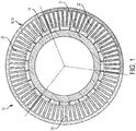
FIG. 1 is a sectional view of a redundant channel motor; -
FIG. 2 is a partial perspective view of the redundant channel motor; and -
FIG. 3 is a sectional view of the redundant channel motor illustrating a stator slot offset according to an aspect of the disclosure. - Referring to
FIG. 1 , a motor is illustrated and generally referenced withnumeral 10. Themotor 10 is physically similar to a brushless DC or AC permanent magnet motor, as it includes arotor 12 that is cylindrical withpermanent magnets 14 attached thereto and surrounded by stator coils. As will be appreciated from the description herein, a stator assembly 16 comprises a plurality of independent stators, referred to herein as stator sectors 18. In the illustrated embodiment, there are three stator sectors, specifically afirst stator sector 20, asecond stator sector 22 and athird stator sector 24. However, it is to be appreciated that it is contemplated that two or more stator sectors may be present in some embodiments. - The
motor 10 may be used in numerous applications that require redundant channels of operation. In some embodiments, themotor 10 is employed as part of an actuator system on an aircraft. In particular, a fly-by-wire aircraft may particularly benefit from the embodiments of themotor 10 described herein. - As noted above, three
stator sectors rotor 12 in the event of failure of one of the other stator sectors. Each stator sector includes its own respective controller and electronics to ensure redundant functionality in the event of failure or unavailability of the other stator sector(s). For example, in operation all threestator sectors rotor 12 prior to failure or unavailability of thethird stator sector 24. Subsequent to loss of thethird stator sector 24, the first andsecond stator sectors rotor 12. Furthermore, in the event of the failure or unavailability of thesecond stator sector 22, thefirst stator sector 20 is capable of independently driving therotor 12. The preceding example is merely illustrative and it is to be understood that any combination of two stator sectors, or any single stator sector (second orthird stator sector 22, 24), is capable of driving therotor 12. Therefore, the stator assembly 16 may be viewed as three independent stators. - The three stator sectors are equally spaced around an entire circumference of the overall stator assembly 16. More particularly, each
stator sector FIG. 2 , with the angle of 120 degrees designated with α. - In fly-by-wire aircraft applications, pilot generated forces are generally small and therefore, under normal operating conditions, the output of the motor is also relatively a small amount of torque. In such cases, the potential is introduced for motor cogging forces to be a significant percentage of the load.
- Referring to
FIG. 3 , to minimize the motor cogging forces present, thestator sectors first slot spacing 26 is defined bystator teeth 28 at a first interface between thefirst stator sector 20 and thesecond stator sector 22. Asecond slot spacing 30 is defined bystator teeth 32 at a second interface between thesecond stator sector 22 and thethird stator sector 24. Athird slot spacing 34 is defined bystator teeth 36 at a third interface between thethird stator sector 24 and thefirst stator sector 20. At least one slot spacing 26, 30 and/or 34 is different than one other slot spacing to offset stator slots of the stator assembly 16. Specifically, eachstator sector third slot spacing 34 are equal. These slot spacings are different than the second slot spacing 30, as shown. - Additional methods of cogging torque reduction are employed in some embodiments. For example, a slotless stator winding, skewed stator slots, bifurcated slots, dummy slots, teeth with different width of the active surface, and decented permanent magnets may be utilized.
- Advantageously, the
motor 10 provides redundancy without added complexity. In the case of failure of a single, or even two stators, the remaining stator continues to drive the load, with no clutching or disconnect functions required. Additionally, overall weight reduction is achieved because the three stators are integrated into a single motor housing. This allows for the stators to share one rotor with magnets, one pair of rotor bearings, and one support structure. Furthermore, motor cogging torque is reduced. This smooths the motor response, especially under light load conditions. - While the disclosure has been described in detail in connection with only a limited number of embodiments, it should be readily understood that the disclosure is not limited to such disclosed embodiments. Rather, the disclosure can be modified to incorporate any number of variations, alterations, substitutions or equivalent arrangements not heretofore described, but which are commensurate with the scope of the disclosure. Additionally, while various embodiments of the disclosure have been described, it is to be understood that aspects of the disclosure may include only some of the described embodiments. Accordingly, the disclosure is not to be seen as limited by the foregoing description, but is only limited by the scope of the appended claims.
Claims (15)
- A redundant channel motor (10) comprising:a permanent magnet rotor (12); anda plurality of stator sectors (18) surrounding the permanent magnet rotor (12), each of the stator sectors (18) disposed in a common plane, independently wound, and capable of driving the load of the permanent magnet rotor (12) in the event of failure of one of the other stator sectors (18).
- The redundant channel motor (10) of claim 1, wherein the plurality of stator sectors (18) comprises a first stator sector (20), a second stator sector (22) and a third stator sector (24).
- The redundant channel motor (10) of claim 2, wherein the first stator sector (20), the second stator sector (22) and the third stator sector (24) each extend 120 degrees around the permanent magnet rotor (12).
- The redundant channel motor (10) of claim 2 or 3, further comprising:a first slot spacing (26) defined by stator teeth (28) at a first interface between the first stator sector (20) and the second stator sector (22);a second slot spacing (30) defined by stator teeth (32) at a second interface between the second stator sector (22) and the third stator sector (24); anda third slot spacing (34) defined by stator teeth (36) at a third interface between the third stator sector (24) and the first stator sector (20);wherein at least one slot spacing (26,30,34) is different than one other slot spacing (26,30,34) to offset the stator slots of each stator sector (20,22,24).
- The redundant channel motor (10) of claim 4, wherein the first slot spacing (26) and the third slot (34) spacing are equal, the second slot spacing (30) being different than the first slot spacing (26) and the third slot spacing (34).
- The redundant channel motor (10) of claim 4 or 5, wherein the first stator sector (20) defines a first plurality of stator slots, the second stator sector (22) defines a second plurality of stator slots, and the third stator sector (24) defines a third plurality of stator slots, each of the first, second and third stator slots having a slot pitch, wherein the offset is equal to one-third of the slot pitch.
- The redundant channel motor (10) of any preceding claim, wherein each of the stator sectors (18) are in operative communication with an independent controller.
- The redundant channel motor (10) of any preceding claim, wherein the motor (10) is included in an actuator system of an aircraft.
- The redundant channel motor (10) of claim 8, wherein the aircraft is a fly-by-wire aircraft.
- The redundant channel motor (10) of any preceding claim, wherein the plurality of stator sectors (18) are redundant such that the motor (10) is operable when only one of three stator sectors (20,22,24) is operational.
- A method of redundantly driving a motor (10) comprising:driving a permanent magnet rotor (12) with a first stator sector (20) and a second stator sector (22), each of the stator sectors (20,22) disposed in a common plane and independently wound; andcontinuing to drive the permanent magnet rotor (12) with one of the stator sectors (20,22) in the event of failure of one of the other stator sectors (20,22).
- The method of claim 11, further comprising:driving the permanent magnet rotor (12) with the first stator sector (20), the second stator sector (22) and a third stator sector (24), each of the stator sectors (20,22,24) disposed in a common plane and independently wound; andcontinuing to drive the permanent magnet rotor (12) with less than all three stator sectors (20,22,24) in the event of failure of at least one of the other stator sectors (20,22,24).
- The method of claim 12, further comprising driving the permanent magnet rotor (12) with a single stator sector (20,22,24) in the event of failure of the other two stator sectors (20,22,24).
- The method of claim 12 or 13, further comprising offsetting the stator sectors (20,22,24) by a distance equal to one-third of a slot pitch of a plurality of slots defined by the stator sectors (20,22,24).
- The method of any of claims 11 to 14, further comprising redundantly driving the motor (10) to drive an actuator system of a fly-by-wire aircraft.
Applications Claiming Priority (1)
| Application Number | Priority Date | Filing Date | Title |
|---|---|---|---|
| US15/273,841 US20180091070A1 (en) | 2016-09-23 | 2016-09-23 | Redundant channel motor and method |
Publications (1)
| Publication Number | Publication Date |
|---|---|
| EP3300214A1 true EP3300214A1 (en) | 2018-03-28 |
Family
ID=59930219
Family Applications (1)
| Application Number | Title | Priority Date | Filing Date |
|---|---|---|---|
| EP17192300.6A Withdrawn EP3300214A1 (en) | 2016-09-23 | 2017-09-21 | Redundant channel motor and method |
Country Status (2)
| Country | Link |
|---|---|
| US (1) | US20180091070A1 (en) |
| EP (1) | EP3300214A1 (en) |
Cited By (3)
| Publication number | Priority date | Publication date | Assignee | Title |
|---|---|---|---|---|
| PL425236A1 (en) * | 2018-04-16 | 2019-10-21 | Yasa Motors Poland Spółka Z Ograniczoną Odpowiedzialnością Spółka Komandytowo-Akcyjna | Multichannel, brushless, axial-jet motor, preferably for applications in the aviation in the electronic control systems |
| EP3599704A1 (en) * | 2018-07-27 | 2020-01-29 | Ge Aviation Systems Llc, Inc. | Stator assembly |
| CN110784048A (en) * | 2018-07-27 | 2020-02-11 | 通用电气航空系统有限责任公司 | Stator assembly |
Families Citing this family (2)
| Publication number | Priority date | Publication date | Assignee | Title |
|---|---|---|---|---|
| DE102018129743A1 (en) * | 2018-11-26 | 2020-05-28 | Schaeffler Technologies AG & Co. KG | PM synchronous motor with device for parameterizing the magnets and integrated braking function |
| US11532969B2 (en) * | 2019-06-19 | 2022-12-20 | The Boeing Company | Actuators and methods for use |
Citations (4)
| Publication number | Priority date | Publication date | Assignee | Title |
|---|---|---|---|---|
| US4550267A (en) * | 1983-02-18 | 1985-10-29 | Sundstrand Corporation | Redundant multiple channel electric motors and generators |
| US6285104B1 (en) * | 1998-05-07 | 2001-09-04 | Okuma Corporation | Motor with reduced torque ripple |
| WO2011148058A2 (en) * | 2010-05-25 | 2011-12-01 | Abb Oy | Winding for an ac machine |
| WO2016030168A1 (en) * | 2014-08-28 | 2016-03-03 | Pascal Chretien | Electromagnetic distributed direct drive for aircraft |
Family Cites Families (3)
| Publication number | Priority date | Publication date | Assignee | Title |
|---|---|---|---|---|
| MY189207A (en) * | 2012-07-12 | 2022-01-31 | Assa Abloy Ab | Method of manufacturing a functional inlay |
| JP2014050211A (en) * | 2012-08-31 | 2014-03-17 | Hitachi Automotive Systems Ltd | Permanent magnet rotary electric machine |
| US20160329758A1 (en) * | 2015-05-08 | 2016-11-10 | Qm Power, Inc. | Magnetically isolated electrical machines |
-
2016
- 2016-09-23 US US15/273,841 patent/US20180091070A1/en not_active Abandoned
-
2017
- 2017-09-21 EP EP17192300.6A patent/EP3300214A1/en not_active Withdrawn
Patent Citations (4)
| Publication number | Priority date | Publication date | Assignee | Title |
|---|---|---|---|---|
| US4550267A (en) * | 1983-02-18 | 1985-10-29 | Sundstrand Corporation | Redundant multiple channel electric motors and generators |
| US6285104B1 (en) * | 1998-05-07 | 2001-09-04 | Okuma Corporation | Motor with reduced torque ripple |
| WO2011148058A2 (en) * | 2010-05-25 | 2011-12-01 | Abb Oy | Winding for an ac machine |
| WO2016030168A1 (en) * | 2014-08-28 | 2016-03-03 | Pascal Chretien | Electromagnetic distributed direct drive for aircraft |
Cited By (3)
| Publication number | Priority date | Publication date | Assignee | Title |
|---|---|---|---|---|
| PL425236A1 (en) * | 2018-04-16 | 2019-10-21 | Yasa Motors Poland Spółka Z Ograniczoną Odpowiedzialnością Spółka Komandytowo-Akcyjna | Multichannel, brushless, axial-jet motor, preferably for applications in the aviation in the electronic control systems |
| EP3599704A1 (en) * | 2018-07-27 | 2020-01-29 | Ge Aviation Systems Llc, Inc. | Stator assembly |
| CN110784048A (en) * | 2018-07-27 | 2020-02-11 | 通用电气航空系统有限责任公司 | Stator assembly |
Also Published As
| Publication number | Publication date |
|---|---|
| US20180091070A1 (en) | 2018-03-29 |
Similar Documents
| Publication | Publication Date | Title |
|---|---|---|
| US20180091070A1 (en) | Redundant channel motor and method | |
| EP2838186B1 (en) | Active-active redundant motor gear system | |
| US7786684B2 (en) | Electromechanical flight control system and method for rotorcraft | |
| EP1863154A2 (en) | Actuation system with redundant motor actuators | |
| EP3101279B1 (en) | Redundant speed summing actuators | |
| CA2831492C (en) | Actuator control system | |
| US20180208299A1 (en) | Actuator in a landing gear system of an aircraft | |
| EP2694364A2 (en) | High lift system for an aircraft | |
| KR102826268B1 (en) | Actuators for aviation applications | |
| US11101762B2 (en) | Linear motor actuators | |
| US20190382108A1 (en) | Actuator for use in aviation | |
| EP2915744B1 (en) | Flight control actuator drive | |
| US20190118936A1 (en) | Pitch actuation system for a turbomachine propeller | |
| CN111365141B (en) | Actuator system, aircraft thrust reverser comprising such a system and aircraft jet engine | |
| EP2505497A1 (en) | Actuator control system | |
| US20180100575A1 (en) | Gearbox assembly | |
| EP3477831A1 (en) | Variable torque electric motor assembly | |
| EP3477845B1 (en) | Variable torque electric motor assembly | |
| US10780976B2 (en) | Simplified pitch actuation system for a turbomachine propeller | |
| US10647411B2 (en) | Electromechanical pitch actuation system for a turbomachine propeller | |
| US12208881B2 (en) | Rotary actuation for thin wing applications | |
| US11780569B2 (en) | Method for controlling an aircraft taxi system | |
| US20190131836A1 (en) | Variable torque electric motor assembly | |
| PL234702B1 (en) | Multichannel, brushless, axial-jet motor, preferably for applications in the aviation in the electronic control systems |
Legal Events
| Date | Code | Title | Description |
|---|---|---|---|
| PUAI | Public reference made under article 153(3) epc to a published international application that has entered the european phase |
Free format text: ORIGINAL CODE: 0009012 |
|
| STAA | Information on the status of an ep patent application or granted ep patent |
Free format text: STATUS: THE APPLICATION HAS BEEN PUBLISHED |
|
| AK | Designated contracting states |
Kind code of ref document: A1 Designated state(s): AL AT BE BG CH CY CZ DE DK EE ES FI FR GB GR HR HU IE IS IT LI LT LU LV MC MK MT NL NO PL PT RO RS SE SI SK SM TR |
|
| AX | Request for extension of the european patent |
Extension state: BA ME |
|
| STAA | Information on the status of an ep patent application or granted ep patent |
Free format text: STATUS: REQUEST FOR EXAMINATION WAS MADE |
|
| 17P | Request for examination filed |
Effective date: 20180926 |
|
| RBV | Designated contracting states (corrected) |
Designated state(s): AL AT BE BG CH CY CZ DE DK EE ES FI FR GB GR HR HU IE IS IT LI LT LU LV MC MK MT NL NO PL PT RO RS SE SI SK SM TR |
|
| STAA | Information on the status of an ep patent application or granted ep patent |
Free format text: STATUS: EXAMINATION IS IN PROGRESS |
|
| 17Q | First examination report despatched |
Effective date: 20190509 |
|
| STAA | Information on the status of an ep patent application or granted ep patent |
Free format text: STATUS: THE APPLICATION HAS BEEN WITHDRAWN |
|
| 18W | Application withdrawn |
Effective date: 20190815 |