EP3300172A1 - Beamsteering using metamaterials - Google Patents
Beamsteering using metamaterials Download PDFInfo
- Publication number
- EP3300172A1 EP3300172A1 EP16190219.2A EP16190219A EP3300172A1 EP 3300172 A1 EP3300172 A1 EP 3300172A1 EP 16190219 A EP16190219 A EP 16190219A EP 3300172 A1 EP3300172 A1 EP 3300172A1
- Authority
- EP
- European Patent Office
- Prior art keywords
- antenna
- electromagnetic wave
- beamsteering
- metamaterial
- beamforming
- Prior art date
- Legal status (The legal status is an assumption and is not a legal conclusion. Google has not performed a legal analysis and makes no representation as to the accuracy of the status listed.)
- Ceased
Links
Images





Classifications
-
- H—ELECTRICITY
- H01—ELECTRIC ELEMENTS
- H01Q—ANTENNAS, i.e. RADIO AERIALS
- H01Q1/00—Details of, or arrangements associated with, antennas
- H01Q1/12—Supports; Mounting means
- H01Q1/22—Supports; Mounting means by structural association with other equipment or articles
- H01Q1/24—Supports; Mounting means by structural association with other equipment or articles with receiving set
- H01Q1/241—Supports; Mounting means by structural association with other equipment or articles with receiving set used in mobile communications, e.g. GSM
- H01Q1/246—Supports; Mounting means by structural association with other equipment or articles with receiving set used in mobile communications, e.g. GSM specially adapted for base stations
-
- H—ELECTRICITY
- H01—ELECTRIC ELEMENTS
- H01Q—ANTENNAS, i.e. RADIO AERIALS
- H01Q15/00—Devices for reflection, refraction, diffraction or polarisation of waves radiated from an antenna, e.g. quasi-optical devices
- H01Q15/0006—Devices acting selectively as reflecting surface, as diffracting or as refracting device, e.g. frequency filtering or angular spatial filtering devices
- H01Q15/0013—Devices acting selectively as reflecting surface, as diffracting or as refracting device, e.g. frequency filtering or angular spatial filtering devices said selective devices working as frequency-selective reflecting surfaces, e.g. FSS, dichroic plates, surfaces being partly transmissive and reflective
- H01Q15/002—Devices acting selectively as reflecting surface, as diffracting or as refracting device, e.g. frequency filtering or angular spatial filtering devices said selective devices working as frequency-selective reflecting surfaces, e.g. FSS, dichroic plates, surfaces being partly transmissive and reflective said selective devices being reconfigurable or tunable, e.g. using switches or diodes
-
- H—ELECTRICITY
- H01—ELECTRIC ELEMENTS
- H01Q—ANTENNAS, i.e. RADIO AERIALS
- H01Q15/00—Devices for reflection, refraction, diffraction or polarisation of waves radiated from an antenna, e.g. quasi-optical devices
- H01Q15/0006—Devices acting selectively as reflecting surface, as diffracting or as refracting device, e.g. frequency filtering or angular spatial filtering devices
- H01Q15/006—Selective devices having photonic band gap materials or materials of which the material properties are frequency dependent, e.g. perforated substrates, high-impedance surfaces
- H01Q15/0066—Selective devices having photonic band gap materials or materials of which the material properties are frequency dependent, e.g. perforated substrates, high-impedance surfaces said selective devices being reconfigurable, tunable or controllable, e.g. using switches
-
- H—ELECTRICITY
- H01—ELECTRIC ELEMENTS
- H01Q—ANTENNAS, i.e. RADIO AERIALS
- H01Q3/00—Arrangements for changing or varying the orientation or the shape of the directional pattern of the waves radiated from an antenna or antenna system
- H01Q3/26—Arrangements for changing or varying the orientation or the shape of the directional pattern of the waves radiated from an antenna or antenna system varying the relative phase or relative amplitude of energisation between two or more active radiating elements; varying the distribution of energy across a radiating aperture
- H01Q3/2605—Array of radiating elements provided with a feedback control over the element weights, e.g. adaptive arrays
- H01Q3/2611—Means for null steering; Adaptive interference nulling
- H01Q3/2617—Array of identical elements
-
- H—ELECTRICITY
- H01—ELECTRIC ELEMENTS
- H01Q—ANTENNAS, i.e. RADIO AERIALS
- H01Q3/00—Arrangements for changing or varying the orientation or the shape of the directional pattern of the waves radiated from an antenna or antenna system
- H01Q3/26—Arrangements for changing or varying the orientation or the shape of the directional pattern of the waves radiated from an antenna or antenna system varying the relative phase or relative amplitude of energisation between two or more active radiating elements; varying the distribution of energy across a radiating aperture
- H01Q3/2658—Phased-array fed focussing structure
-
- H—ELECTRICITY
- H01—ELECTRIC ELEMENTS
- H01Q—ANTENNAS, i.e. RADIO AERIALS
- H01Q3/00—Arrangements for changing or varying the orientation or the shape of the directional pattern of the waves radiated from an antenna or antenna system
- H01Q3/44—Arrangements for changing or varying the orientation or the shape of the directional pattern of the waves radiated from an antenna or antenna system varying the electric or magnetic characteristics of reflecting, refracting, or diffracting devices associated with the radiating element
- H01Q3/46—Active lenses or reflecting arrays
Definitions
- This invention relates a method and apparatus for beamsteering at an antenna in a mobile base station in a telecommunications network.
- MIMO radio systems are designed to improve robustness and throughput of wireless transmission links, and is a fundamental technology in wireless technologies such as the 4th Generation (4G) Long Term Evolution (LTE) protocol.
- a MIMO radio system consists of a number of transmit and receive antennas, providing functions such as transmit diversity, spatial multiplexing, and beamforming.
- Transmit diversity is when the same data is transmitted redundantly over more than one antenna to improve robustness of transmission.
- Spatial multiplexing is when the data is divided into separate streams to increase throughput.
- Beamforming is when multiple antenna elements are controlled to form beams in certain direction/shape by applying individual transmission magnitude and phase weights to each antenna element forming array gains (also referred to as beamforming gains).
- Beamforming in the downlink direction is illustrated in Figure 1 from a transmitter 102 to a receiver 104 (e.g. mobile base station to a mobile terminal), where a main beam 106 is formed for the receiver 104.
- the beamforming uses direction of arrival and path loss information, which are derived from uplink measurements from the receiver 108 to the transmitter 102. With beamforming, it is possible for a transmitter to provide better coverage to a certain area, for example along a cell edge to improve the Signal to Noise and Interference Ratio (SINR), and ultimately the network's spectral efficiency.
- SINR Signal to Noise and Interference Ratio
- beamforming can be used to supress some interference by applying a null beam pattern to the interference source in adaptive manner.
- receiver 104 Whilst the transmitter 102 forms a beam 106 for receipt by the receiver 104, side-lobes typically result, such as side-lobe 110 and 114. Here, side-lobe 110 is received as interference by receiver 108. However, receiver 112 can null the interference from side-lobe 114 using a suitable null beam pattern.
- Figure 2 illustrates a linear array antenna (top view) with d being the distance between each of the antenna elements 102a-102e. Typically d> ⁇ /2, where ⁇ is the carrier wavelength of the transmitted wave. Assuming a plane wavefront, the wave will traverse additional distance (d * sin ⁇ ) to the next antenna element at the speed of light c. Elements are usually identical and can be of any antenna type.
- the total field of an antenna array is the vector superposition of fields radiated by the each individual element. For beamformed beam patterns of some shape, the partial fields generated by the individual elements interfere in a constructive manner in the desired direction and interfere destructively in the remaining space. This can be is controlled by the phase and amplitude weights W n applied to the beam signal for each element.
- the geometric dimensions and arrangement of the elements of an antenna array significantly affect the radiation characteristics and beamforming capabilities of the antenna.
- Conventional base station antennas typically consist of multiple orthogonal cross-polarized elements in the vertical and horizontal planes or at 45 degree to each other as illustrated in Figure 3 . Outer elements are used for spatial diversity and inner elements for beamforming (+45° or -45°). This usually results in a very wide antenna beam patterns deliberately designed to provide as much coverage as possible. However, this type of wide beam antenna configuration is not ideal for separating users or group of users, particularly in small range cells.
- Multi-user MIMO (Transmission mode 5) and Dual Layer Beamforming (Transmission mode 8) are two of the most advanced transmission modes in LTE. Beamforming is a fundamental technique in these transmission modes as it can increase the signal strength at the receiver by up to a factor that is proportional to the number of transmit antennas. For these modes to perform effectively, the formed antenna beams, which are shaped in direction of a target receiver(s) and use the same time and frequency resources but different codewords, need to be spatially separated in order to avoid interference amongst receivers or a group of receivers.
- the basestation can select receivers that report orthogonal precoding matrix indicators (PMIs) and create beams for each one or groups of receivers whose channel fading conditions are similar except for direction dependent phase difference.
- PMIs orthogonal precoding matrix indicators
- a method known as beamsteering can be applied to steer the formed beam in different directions by applying different phase shifts to the signals transmitted on different antenna elements.
- each antenna element requires a phase shifter in either the analogue or digital domain, which limits beamsteering to only small-scale MIMO architectures.
- a phase shifter for each antenna element is not economical for mass market and commercial deployments.
- antenna elements are usually closely spaced in order to achieve high correlation paths that add constructively at the receiver location to create the beams.
- This short separation distance between antenna elements results in a very wide beam, and imposes limits on both the dimensioning and shaping of the coverage areas and the ability to spatially decorrelate users.
- creating narrower beam widths is possible by simply making the antenna element separation larger (in the order of multiple wavelengths), the result would be physically larger antennas, which is in practice is problematic for small cells.
- narrow beam antennas are typically associated with undesirable, high side-lobes which sharply increase interference levels to other receivers.
- a transmitter for a base station in a cellular telecommunications network comprising:
- the metamaterial beamsteering structure may be tuned to resonate at the carrier frequency of the transmitted electromagnetic wave.
- the desired direction may be a direction towards a receiver, and the desired direction may be determined using direction of arrival feedback information received by the base station from the receiver.
- the metamaterial beamsteering structure may be positioned in the near-field region of the antenna.
- Examples of the invention complement beamforming in LTE links based on beamsteering using active metamaterial transmitarray structures that attach to an existing mobile basestation antenna.
- Standard LTE beamsteering/beamforming methods which are based on selecting antenna weight coefficients from codebook lookup tables, can be further optimised with this approach to improve coverage by focusing or steering the beam in a certain direction. As such, capacity can be improved by reducing interference levels.
- the structure itself consists of standard of-the-shelf PCB materials and surface mount components, making it ideal for mass production economics, resonating at the required carrier frequency and exhibiting filtering/beamsteering capabilities at an RF level within the antenna's near-field region.
- Standard basestation antennas with RF phase shifters provide elevation tilt only.
- Embodiments of the invention can provide azimuth tilt capabilities as an extra spatial degree of freedom.
- the metamaterial structure invention eliminates the need for expensive phase shifters for each or group of antenna elements, which are very costly and present implementation challenges for economic mass productions.
- Examples of the invention present a transmitter arrangement comprising a standard beamforming antenna in conjunction with an active metamaterial structure that provides beamsteering capability and attaches to the existing antenna.
- the metamaterial structure is active and digitally controlled, positioned in the near-field region of the main antenna elements, and behaves like a phase shifter.
- Standard antenna arrangements can be further optimised with this approach, which improves coverage by focusing or steering the beam in a certain direction, and improves capacity by reducing interference levels.
- FIG. 4 is a block diagram illustrating the physical (PHY) downlink modules 400 in a known LTE system.
- the process of converting bit streams into RF structured transmission starts at the scrambling module 402, which performs scrambling to help reduce interference levels at the receiver. This is implemented by multiplying the coded sequence of bits by a scrambling sequence at the bit level.
- the modulation mapper 404 then maps the scrambled bit values into complex modulation symbols such as QPSK (Quadrature phase shift keying), 16QAM (Quadrature Amplitude Modulation) and 64QAM (Quadrature Amplitude Modulation).
- the layer mapper 406 splits the modulated data sequence bits into a number of layers depending on the transmission scheme used.
- Precoding at the precoding module 410 is a technique used to adapt the transmitted complex waveforms to the channel conditions with an appropriate gain and phase weighting in order to maximize the received signal level at the receiver side.
- each layer is mapped to an antenna port and all layers are multiplied by a precoding matrix W selected from a predefined codebook. This selection is based on feedback from the receiver in the form a precoding matrix indicator (PMI) as part of the channel state information (CSI) along with the rank indicator (RI).
- PMI precoding matrix indicator
- CSI channel state information
- RI rank indicator
- RI refers to how many layers the receiver can support at a given instantaneous channel condition for downlink transmission, which is fed back to the base station in terms of the index, i.e. the PMI, of the most suitable matrix from the predefined codebook table known to both the transmitter and receiver.
- the resource-mapping block 412 maps the resulting precoded data symbols onto specific resource elements (the subcarriers and symbols) from the resource grid.
- the signal generator 414 generates the final (time-domain OFDM) signal for the antenna 416.
- FIG. 5 shows a simplified block diagram of a transmitter in an example of the present invention.
- the transmitter 500 comprises a standard LTE antenna 502 and a further metamaterial beamsteering structure 504 positioned in the transmission path of the antenna 502.
- the metamaterial beamsteering structure 504 positioned in the near-field region of the antenna 502.
- the antenna 502 is connected to a control unit 506, and the metamaterial structure 504 is connected to control unit 508.
- the control units control the operation of the respective antenna and metamaterial structure. Whilst two control units have been shown, the control units may be implemented as a single control unit.
- the antenna 502 is capable of beamforming and transmits an electromagnetic wave (or beam), which is received at the metamaterial structure 504.
- the metamaterial structure 504, a type of transmitarray acts like a phase shifter by introducing phase delays into the incident electromagnetic wave, beamsteering the electromagnetic wave in a direction controlled by the control unit 508.
- additional beam steering is applied to the beam output by the antenna 502 (at the RF signal level) using the metamaterial transmitarray structure 504, which is positioned in the transmission path of the antenna 502.
- Operating at the RF level means no changes are required to the baseband or the actual radio of the existing antenna.
- the weighting vector a is effectively applied by the metamaterial structure at the RF level.
- FIG. 6 is a block diagram illustrating the physical (PHY) downlink modules 600 in an example of the present invention.
- the system 600 in Figure 6 shares many of the modules with the known LTE system shown in Figure 4 , with like reference numerals used to identify such modules.
- the metamaterial structure 602 is positioned after the antenna 416, and is controlled a digital controller 604.
- the digital controller 604 which corresponds to the controller 508 in Figure 5 , controls the phase delays introduced by the metamaterial structure, and thus the direction the beam is steered in.
- the metamaterial structure is comprised of a number of unit-cells arranged in a planar array.
- An example of a unit-cell 700 is illustrated in Figure 7a .
- Unit-cell 700 is a printed circuit board forming a square slot frequency selective surface (FSS), loaded with surface mount components (SMC), resulting in spatial band-pass filtering characteristics with phase control capabilities.
- the SMCs are varactor diodes, which vary in capacitance in dependence on the voltage applied to them.
- the unit-cell 700 can be decomposed to an equivalent resonant circuit (or LC circuit) 702 as shown in Figure 7b exhibiting the corresponding resonant behaviour.
- L represents the inductance effect of the vertical wire with thickness w and length I
- Cg represents the capacitance introduced by the gap g with length d
- C smd represents the capacitance resulting from the surface mount capacitors.
- the unit-cell can be tuned to a resonant frequency f 0 matching that of the carrier frequency of the electromagnetic wave transmitted by the antenna 502.
- a plurality of unit cells (700a to 700e) are stacked on top of each other as shown in Figure 7c .
- the cells are stacked to create the effect of an optical RF filter, with the number of layers affecting the beam steering angle and filtering performance.
- An electromagnetic wave passing through the metamaterial structure will experience a phase delay that is dependent on the capacitance of the varactor diodes.
- the capacitance of each unit cell can be varied, which in turn varies the phase delay experienced by an electromagnetic wave passing through the respective unit cell.
- the electromagnetic wave can be steered in a desired direction, theta ( ⁇ ).
- the metamaterial structure is controlled by the digital controller 604.
- the digital controller 604 can use direction of arrival feedback information from the receiver available at the base station to set a desired steering direction ⁇ towards the receiver.
- the controller 604 adjusts the voltages applied to the varactor diodes in each unit cell in the metamaterial structure to induce the required phase delay to cause the electromagnetic wave received from the antenna to be steered to in the desired steering direction ⁇ .
- the unit-cell When the metamaterial structure is excited by an incident electromagnetic wave from the base station antenna with a carrier frequency close to the structure's resonant frequency f 0 , due to the structure's band-pass frequency response, the unit-cell will allow the wave to propagate through the metamaterial structure with minimum insertion loss.
- Design criteria for the unit cell is fundamentally dependent on the antenna geometry and the frequency range of operation.
- a unit-cell with dimensions and substrate detailed in Table I of Figure 7d is designed to exhibit a band-pass response shifted from 5 GHz to 5.5 GHz when the capacitance (C smd ) is varied from 2.8 pF to 0.7 pF.
Landscapes
- Physics & Mathematics (AREA)
- Optics & Photonics (AREA)
- Engineering & Computer Science (AREA)
- Computer Networks & Wireless Communication (AREA)
- Variable-Direction Aerials And Aerial Arrays (AREA)
Abstract
Examples of the invention present a transmitter arrangement comprising a standard beamforming antenna in conjunction with an active metamaterial structure that provides beamsteering capability and attaches to the existing antenna. The metamaterial structure is active and digitally controlled, positioned in front of the main antenna elements, and behaves like a phase shifter. Thus, additional beamsteering functionality is provided to existing beamforming arrangements without the need to change the existing basestation antenna. Standard antenna arrangements can be can be further optimised with this approach, which improves coverage by focusing or steering the beam in a certain direction, and improves capacity by reducing interference levels.
Description
- This invention relates a method and apparatus for beamsteering at an antenna in a mobile base station in a telecommunications network.
- Multiple Input Multiple Output (MIMO) radio systems are designed to improve robustness and throughput of wireless transmission links, and is a fundamental technology in wireless technologies such as the 4th Generation (4G) Long Term Evolution (LTE) protocol. A MIMO radio system consists of a number of transmit and receive antennas, providing functions such as transmit diversity, spatial multiplexing, and beamforming. Transmit diversity is when the same data is transmitted redundantly over more than one antenna to improve robustness of transmission. Spatial multiplexing is when the data is divided into separate streams to increase throughput. Beamforming is when multiple antenna elements are controlled to form beams in certain direction/shape by applying individual transmission magnitude and phase weights to each antenna element forming array gains (also referred to as beamforming gains).
- Beamforming in the downlink direction is illustrated in
Figure 1 from atransmitter 102 to a receiver 104 (e.g. mobile base station to a mobile terminal), where amain beam 106 is formed for thereceiver 104. The beamforming uses direction of arrival and path loss information, which are derived from uplink measurements from thereceiver 108 to thetransmitter 102. With beamforming, it is possible for a transmitter to provide better coverage to a certain area, for example along a cell edge to improve the Signal to Noise and Interference Ratio (SINR), and ultimately the network's spectral efficiency. On the receiver side, if direction of arrival information is available, beamforming can be used to supress some interference by applying a null beam pattern to the interference source in adaptive manner. Whilst thetransmitter 102 forms abeam 106 for receipt by thereceiver 104, side-lobes typically result, such as side-lobe lobe 110 is received as interference byreceiver 108. However,receiver 112 can null the interference from side-lobe 114 using a suitable null beam pattern. -
Figure 2 illustrates a linear array antenna (top view) with d being the distance between each of theantenna elements 102a-102e. Typically d>λ/2, where λ is the carrier wavelength of the transmitted wave. Assuming a plane wavefront, the wave will traverse additional distance (d * sin θ) to the next antenna element at the speed of light c. Elements are usually identical and can be of any antenna type. The total field of an antenna array is the vector superposition of fields radiated by the each individual element. For beamformed beam patterns of some shape, the partial fields generated by the individual elements interfere in a constructive manner in the desired direction and interfere destructively in the remaining space. This can be is controlled by the phase and amplitude weights Wn applied to the beam signal for each element. - The geometric dimensions and arrangement of the elements of an antenna array significantly affect the radiation characteristics and beamforming capabilities of the antenna.
- Conventional base station antennas typically consist of multiple orthogonal cross-polarized elements in the vertical and horizontal planes or at 45 degree to each other as illustrated in
Figure 3 . Outer elements are used for spatial diversity and inner elements for beamforming (+45° or -45°). This usually results in a very wide antenna beam patterns deliberately designed to provide as much coverage as possible. However, this type of wide beam antenna configuration is not ideal for separating users or group of users, particularly in small range cells. - There is a need to isolate users spatially to allow a basestation to reuse the same time and frequency resources in different beam directions with limited interference in order to maximise spectral efficiency. Also, as typical basestation antennas have relatively wide beams to give as large a coverage area as possible, any changes in beams would be very limited.
- Multi-user MIMO (Transmission mode 5) and Dual Layer Beamforming (Transmission mode 8) are two of the most advanced transmission modes in LTE. Beamforming is a fundamental technique in these transmission modes as it can increase the signal strength at the receiver by up to a factor that is proportional to the number of transmit antennas. For these modes to perform effectively, the formed antenna beams, which are shaped in direction of a target receiver(s) and use the same time and frequency resources but different codewords, need to be spatially separated in order to avoid interference amongst receivers or a group of receivers. The basestation can select receivers that report orthogonal precoding matrix indicators (PMIs) and create beams for each one or groups of receivers whose channel fading conditions are similar except for direction dependent phase difference. A method known as beamsteering can be applied to steer the formed beam in different directions by applying different phase shifts to the signals transmitted on different antenna elements. To effect beamsteering, each antenna element requires a phase shifter in either the analogue or digital domain, which limits beamsteering to only small-scale MIMO architectures. For a Massive MIMO type antenna with elements exceeding 100x100, a phase shifter for each antenna element is not economical for mass market and commercial deployments.
- Furthermore, antenna elements are usually closely spaced in order to achieve high correlation paths that add constructively at the receiver location to create the beams. This short separation distance between antenna elements results in a very wide beam, and imposes limits on both the dimensioning and shaping of the coverage areas and the ability to spatially decorrelate users. Although creating narrower beam widths is possible by simply making the antenna element separation larger (in the order of multiple wavelengths), the result would be physically larger antennas, which is in practice is problematic for small cells. Furthermore, narrow beam antennas are typically associated with undesirable, high side-lobes which sharply increase interference levels to other receivers.
- It is the aim of embodiments of the present invention to provide an improved method and apparatus for beamsteering at an antenna.
- According to one aspect of the present invention, there is provided a transmitter for a base station in a cellular telecommunications network, the transmitter comprising:
- an antenna for transmitting an electromagnetic wave, wherein the antenna comprises a plurality of antenna elements;
- a control unit adapted to control the transmission of the electromagnetic wave by the antenna, wherein the processor controls the direction of transmission of the electromagnetic wave using a beamforming technique applied to the plurality of antenna elements; and
- a metamaterial beamsteering structure positioned in a transmission path of the antenna, the metamaterial beamsteering structure comprising an array of active elements adapted to receive the electromagnetic wave from the antenna and to output a steered electromagnetic wave towards a desired direction, wherein each element in the array is controllable by the control unit to cause a corresponding phase delay to be introduced into the received electromagnetic wave by said element such that the steered electromagnetic wave has a steering angle that is dependent on the phase delays.
- The metamaterial beamsteering structure may be tuned to resonate at the carrier frequency of the transmitted electromagnetic wave.
- The desired direction may be a direction towards a receiver, and the desired direction may be determined using direction of arrival feedback information received by the base station from the receiver.
- The metamaterial beamsteering structure may be positioned in the near-field region of the antenna.
- Examples of the invention complement beamforming in LTE links based on beamsteering using active metamaterial transmitarray structures that attach to an existing mobile basestation antenna. Standard LTE beamsteering/beamforming methods, which are based on selecting antenna weight coefficients from codebook lookup tables, can be further optimised with this approach to improve coverage by focusing or steering the beam in a certain direction. As such, capacity can be improved by reducing interference levels.
- The structure itself consists of standard of-the-shelf PCB materials and surface mount components, making it ideal for mass production economics, resonating at the required carrier frequency and exhibiting filtering/beamsteering capabilities at an RF level within the antenna's near-field region.
- By applying beamsteering at the antenna's near-field makes the arrangement transparent to existing base station or customer premises antennas.
- Standard basestation antennas with RF phase shifters provide elevation tilt only. Embodiments of the invention can provide azimuth tilt capabilities as an extra spatial degree of freedom.
- For forthcoming Massive MIMO architectures in 5G networks, which will typically consist of a very large number of antenna elements, the metamaterial structure invention eliminates the need for expensive phase shifters for each or group of antenna elements, which are very costly and present implementation challenges for economic mass productions.
- For a better understanding of the present invention, reference will now be made by way of example only to the accompanying drawings, in which:
-
Figure 1 illustrates beamforming in the downlink direction from a transmitter to a receiver; -
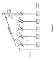
Figure 2 illustrates a linear array antenna arranged for beamforming; -
Figure 3 is a schematic diagram of the elements in an antenna array; -
Figure 4 is a block diagram of the physical downlink modules in an LTE system; -
Figure 5 is a simplified block diagram of a transmitter in an example of the present invention; -
Figure 6 is a block diagram of the physical downlink modules in an example of the present invention; -
Figure 7a is a simplified diagram of a unit cell forming part of the metamaterial structure in an example of the invention; -
Figure 7b is an equivalent resonant circuit for the unit cell in an example of the present invention; -
Figure 7c shows a series of stacked unit cells in an example of the present invention; -
Figure 7d is a table showing example unit-cell dimensions. - The present invention is described herein with reference to particular examples. The invention is not, however, limited to such examples.
- Examples of the invention present a transmitter arrangement comprising a standard beamforming antenna in conjunction with an active metamaterial structure that provides beamsteering capability and attaches to the existing antenna. The metamaterial structure is active and digitally controlled, positioned in the near-field region of the main antenna elements, and behaves like a phase shifter. Thus, additional beamsteering functionality is provided to existing beamforming arrangements without the need to change the existing basestation antenna. Standard antenna arrangements can be can be further optimised with this approach, which improves coverage by focusing or steering the beam in a certain direction, and improves capacity by reducing interference levels.
-
Figure 4 is a block diagram illustrating the physical (PHY)downlink modules 400 in a known LTE system. The process of converting bit streams into RF structured transmission starts at the scrambling module 402, which performs scrambling to help reduce interference levels at the receiver. This is implemented by multiplying the coded sequence of bits by a scrambling sequence at the bit level. Themodulation mapper 404 then maps the scrambled bit values into complex modulation symbols such as QPSK (Quadrature phase shift keying), 16QAM (Quadrature Amplitude Modulation) and 64QAM (Quadrature Amplitude Modulation). Thelayer mapper 406 splits the modulated data sequence bits into a number of layers depending on the transmission scheme used. Precoding at theprecoding module 410 is a technique used to adapt the transmitted complex waveforms to the channel conditions with an appropriate gain and phase weighting in order to maximize the received signal level at the receiver side. Specifically, each layer is mapped to an antenna port and all layers are multiplied by a precoding matrix W selected from a predefined codebook. This selection is based on feedback from the receiver in the form a precoding matrix indicator (PMI) as part of the channel state information (CSI) along with the rank indicator (RI). RI refers to how many layers the receiver can support at a given instantaneous channel condition for downlink transmission, which is fed back to the base station in terms of the index, i.e. the PMI, of the most suitable matrix from the predefined codebook table known to both the transmitter and receiver. - The resource-
mapping block 412 maps the resulting precoded data symbols onto specific resource elements (the subcarriers and symbols) from the resource grid. Thesignal generator 414 generates the final (time-domain OFDM) signal for theantenna 416. - Note
Figure 4 shows two streams to indicate the use of two codewords per symbol. -
Figure 5 shows a simplified block diagram of a transmitter in an example of the present invention. Thetransmitter 500 comprises astandard LTE antenna 502 and a furthermetamaterial beamsteering structure 504 positioned in the transmission path of theantenna 502. Themetamaterial beamsteering structure 504 positioned in the near-field region of theantenna 502. Theantenna 502 is connected to acontrol unit 506, and themetamaterial structure 504 is connected to controlunit 508. The control units control the operation of the respective antenna and metamaterial structure. Whilst two control units have been shown, the control units may be implemented as a single control unit. Theantenna 502 is capable of beamforming and transmits an electromagnetic wave (or beam), which is received at themetamaterial structure 504. Themetamaterial structure 504, a type of transmitarray, acts like a phase shifter by introducing phase delays into the incident electromagnetic wave, beamsteering the electromagnetic wave in a direction controlled by thecontrol unit 508. - For beamforming under LTE, antenna weights are applied at the baseband level and the patterns are formed by assigning a complex weight W to the signal and combining them to form an array output as follows:

precoding module 410. - In examples of the present invention, additional beam steering is applied to the beam output by the antenna 502 (at the RF signal level) using the
metamaterial transmitarray structure 504, which is positioned in the transmission path of theantenna 502. Operating at the RF level means no changes are required to the baseband or the actual radio of the existing antenna. The resulting beamsteered signal can be expressed in vector notation as the application of a further precoding vector, or weighting vector,a to ybf as follows:
- The weighting vector
a is effectively applied by the metamaterial structure at the RF level. -
Figure 6 is a block diagram illustrating the physical (PHY)downlink modules 600 in an example of the present invention. Thesystem 600 inFigure 6 shares many of the modules with the known LTE system shown inFigure 4 , with like reference numerals used to identify such modules. As can be seen, the metamaterial structure 602 is positioned after theantenna 416, and is controlled adigital controller 604. Thedigital controller 604, which corresponds to thecontroller 508 inFigure 5 , controls the phase delays introduced by the metamaterial structure, and thus the direction the beam is steered in. - The metamaterial structure is comprised of a number of unit-cells arranged in a planar array. An example of a unit-
cell 700 is illustrated inFigure 7a . Unit-cell 700 is a printed circuit board forming a square slot frequency selective surface (FSS), loaded with surface mount components (SMC), resulting in spatial band-pass filtering characteristics with phase control capabilities. Specifically, the SMCs are varactor diodes, which vary in capacitance in dependence on the voltage applied to them. - The unit-
cell 700 can be decomposed to an equivalent resonant circuit (or LC circuit) 702 as shown inFigure 7b exhibiting the corresponding resonant behaviour. For an incident electromagnetic wave that is vertically polarized (TE mode), L represents the inductance effect of the vertical wire with thickness w and length I, Cg represents the capacitance introduced by the gap g with length d and, Csmd represents the capacitance resulting from the surface mount capacitors. The resonant frequency f0 can be calculated as follows:
- Thus, the unit-cell can be tuned to a resonant frequency f0 matching that of the carrier frequency of the electromagnetic wave transmitted by the
antenna 502. - In examples of the invention, a plurality of unit cells (700a to 700e) are stacked on top of each other as shown in
Figure 7c . The cells are stacked to create the effect of an optical RF filter, with the number of layers affecting the beam steering angle and filtering performance. - An electromagnetic wave passing through the metamaterial structure will experience a phase delay that is dependent on the capacitance of the varactor diodes. Thus, by adjusting the voltage applied to the varactor diodes of each unit cell, the capacitance of each unit cell can be varied, which in turn varies the phase delay experienced by an electromagnetic wave passing through the respective unit cell. By adjusting the phase delay at each unit cell, the electromagnetic wave can be steered in a desired direction, theta (θ).
- The metamaterial structure is controlled by the
digital controller 604. Thedigital controller 604 can use direction of arrival feedback information from the receiver available at the base station to set a desired steering direction θ towards the receiver. Thecontroller 604 adjusts the voltages applied to the varactor diodes in each unit cell in the metamaterial structure to induce the required phase delay to cause the electromagnetic wave received from the antenna to be steered to in the desired steering direction θ. - The principle of beamsteering using the metamaterial structure is shown in
Figure 8 and can be compared to the one of a typical linear antenna array as illustrated inFigure 2 . Whilst in a linear antenna array the phase shifting is applied to the signal in each individual branch using a phase shifter, in the metamaterial structure the phase shifting in obtained by controlling the phase delay introduced by the individual elements of the transmitarray. As the incident electromagnetic wave penetrates through a transmitarray of length I, composed by N elements (unit cells) of periodicity p (p=I/N), it experiences different phase shifting Yn after penetrating each of the elements of the array in the steering direction theta (θ), as a result of the phase delay induced by each element. Yn can be calculated as:
- Consequently, the transmission phase (phase delay described earlier) αn in the nth element can be defined by the following equation where α0 is the phase of the incident EM wave received by the transmitarray:

- The retransmitted wave in the direction of θ can be expressed as function of the progressive phase, i.e. the phase difference Ψ between adjacent elements:

- Thus, by varying the phase of each element (or unit cell) in the array in a progressive way, with a phase difference between adjacent elements defined by Ψ in equation (6), an incident electromagnetic wave can be steered to a desired direction of θ. Equation (6) can be rewritten to give the desired steering direction as:

- When the metamaterial structure is excited by an incident electromagnetic wave from the base station antenna with a carrier frequency close to the structure's resonant frequency f0, due to the structure's band-pass frequency response, the unit-cell will allow the wave to propagate through the metamaterial structure with minimum insertion loss.
- Design criteria for the unit cell is fundamentally dependent on the antenna geometry and the frequency range of operation. For example, a unit-cell with dimensions and substrate detailed in Table I of
Figure 7d is designed to exhibit a band-pass response shifted from 5 GHz to 5.5 GHz when the capacitance (Csmd) is varied from 2.8 pF to 0.7 pF. - In general, it is noted herein that while the above describes examples of the invention, there are several variations and modifications which may be made to the described examples without departing from the scope of the present invention as defined in the appended claims. One skilled in the art will recognise modifications to the described examples.
Claims (5)
- A transmitter for a base station in a cellular telecommunications network, the transmitter comprising:an antenna for transmitting an electromagnetic wave, wherein the antenna comprises a plurality of antenna elements;a control unit adapted to control the transmission of the electromagnetic wave by the antenna, wherein the processor controls the direction of transmission of the electromagnetic wave using a beamforming technique applied to the plurality of antenna elements;a metamaterial beamsteering structure positioned in a transmission path of the antenna, the metamaterial beamsteering structure comprising an array of active elements adapted to receive the electromagnetic wave from the antenna and to output a steered electromagnetic wave towards a desired direction, wherein each element in the array is controllable by the control unit to cause a corresponding phase delay to be introduced into the received electromagnetic wave by said element such that the steered electromagnetic wave has a steering angle that is dependent on the phase delays.
- A transmitter according to claim 1, wherein the metamaterial beamsteering structure is tuned to resonate at the carrier frequency of the transmitted electromagnetic wave.
- A transmitter according to claim 1 or 2, wherein the desired direction is a direction to a receiver.
- A transmitter according to claim 3, wherein the desired direction is set using direction of arrival feedback information from the receiver.
- A transmitter according to any preceding claim, wherein the metamaterial beamsteering structure is positioned in the near-field region of the antenna.
Priority Applications (1)
| Application Number | Priority Date | Filing Date | Title |
|---|---|---|---|
| EP16190219.2A EP3300172A1 (en) | 2016-09-22 | 2016-09-22 | Beamsteering using metamaterials |
Applications Claiming Priority (1)
| Application Number | Priority Date | Filing Date | Title |
|---|---|---|---|
| EP16190219.2A EP3300172A1 (en) | 2016-09-22 | 2016-09-22 | Beamsteering using metamaterials |
Publications (1)
| Publication Number | Publication Date |
|---|---|
| EP3300172A1 true EP3300172A1 (en) | 2018-03-28 |
Family
ID=56985552
Family Applications (1)
| Application Number | Title | Priority Date | Filing Date |
|---|---|---|---|
| EP16190219.2A Ceased EP3300172A1 (en) | 2016-09-22 | 2016-09-22 | Beamsteering using metamaterials |
Country Status (1)
| Country | Link |
|---|---|
| EP (1) | EP3300172A1 (en) |
Cited By (12)
| Publication number | Priority date | Publication date | Assignee | Title |
|---|---|---|---|---|
| CN110165414A (en) * | 2019-05-13 | 2019-08-23 | 复旦大学 | A kind of super surface of reflection-type broadband 4-bit coding for Broadband RCS decrement |
| CN110855589A (en) * | 2019-10-31 | 2020-02-28 | 东南大学 | Time domain coding super surface for realizing wireless communication of multiple modulation schemes |
| CN111313157A (en) * | 2020-02-28 | 2020-06-19 | 重庆邮电大学 | A dual-beam reflection-encoded metasurface |
| CN111853154A (en) * | 2020-07-20 | 2020-10-30 | 上海交通大学 | Actively Coded Tunable Metamaterial System for Broadband Vibration Isolation in the Low Frequency Domain |
| EP3675283A4 (en) * | 2018-04-17 | 2021-01-13 | Southeast University | DIRECT RADIATION WIRELESS DIGITAL COMMUNICATION SYSTEM AND METHOD BASED ON DIGITAL CODING METAMATERIAL |
| WO2021107327A1 (en) | 2019-11-29 | 2021-06-03 | Samsung Electronics Co., Ltd. | Method and apparatus for transmitting and receiving signal in wireless communication system |
| EP3756237A4 (en) * | 2018-02-22 | 2021-11-24 | University Of Massachusetts | ANTENNA HARDWARE AND CONTROL |
| WO2022112553A1 (en) * | 2020-11-30 | 2022-06-02 | Sony Group Corporation | Re-configurable repeater device including beam-shaping unit |
| US20220294112A1 (en) * | 2021-02-25 | 2022-09-15 | ST Engineering iDirect, Inc. dba iDirect | Unit cell for a reconfigurable antenna |
| EP4246724A1 (en) * | 2022-03-14 | 2023-09-20 | Tata Consultancy Services Limited | Metasurface beam steering antenna and method of setting antenna beam angle |
| JP2025513472A (en) * | 2022-05-07 | 2025-04-24 | 中興通訊股▲ふん▼有限公司 | Air-interface electrically tunable metasurfaces and radiating devices |
| WO2025098690A1 (en) * | 2023-11-08 | 2025-05-15 | British Telecommunications Public Limited Company | A device comprising a transceiver and protective enclosure |
Citations (2)
| Publication number | Priority date | Publication date | Assignee | Title |
|---|---|---|---|---|
| WO2008115881A1 (en) * | 2007-03-16 | 2008-09-25 | Rayspan Corporation | Metamaterial antenna arrays with radiation pattern shaping and beam switching |
| US20150009070A1 (en) * | 2010-11-03 | 2015-01-08 | Hrl Laboratories, Llc | Low cost, 2d, electronically-steerable, artificial-impedance-surface antenna |
-
2016
- 2016-09-22 EP EP16190219.2A patent/EP3300172A1/en not_active Ceased
Patent Citations (2)
| Publication number | Priority date | Publication date | Assignee | Title |
|---|---|---|---|---|
| WO2008115881A1 (en) * | 2007-03-16 | 2008-09-25 | Rayspan Corporation | Metamaterial antenna arrays with radiation pattern shaping and beam switching |
| US20150009070A1 (en) * | 2010-11-03 | 2015-01-08 | Hrl Laboratories, Llc | Low cost, 2d, electronically-steerable, artificial-impedance-surface antenna |
Non-Patent Citations (1)
| Title |
|---|
| KIHUN CHANG ET AL: "active frequency selective surfaces using incorporated PIN diodes", IEICE TRANSACTIONS ON ELECTRONICS, INSTITUTE OF ELECTRONICS, TOKYO, JP, vol. E91-C, no. 12, 1 December 2008 (2008-12-01), pages 1917 - 1922, XP002582503, ISSN: 0916-8524, DOI: 10.1093/IETELE/E91-C.12.1917 * |
Cited By (17)
| Publication number | Priority date | Publication date | Assignee | Title |
|---|---|---|---|---|
| EP3756237A4 (en) * | 2018-02-22 | 2021-11-24 | University Of Massachusetts | ANTENNA HARDWARE AND CONTROL |
| US11811138B2 (en) * | 2018-02-22 | 2023-11-07 | University Of Massachusetts | Antenna hardware and control |
| EP3675283A4 (en) * | 2018-04-17 | 2021-01-13 | Southeast University | DIRECT RADIATION WIRELESS DIGITAL COMMUNICATION SYSTEM AND METHOD BASED ON DIGITAL CODING METAMATERIAL |
| CN110165414A (en) * | 2019-05-13 | 2019-08-23 | 复旦大学 | A kind of super surface of reflection-type broadband 4-bit coding for Broadband RCS decrement |
| CN110855589A (en) * | 2019-10-31 | 2020-02-28 | 东南大学 | Time domain coding super surface for realizing wireless communication of multiple modulation schemes |
| CN110855589B (en) * | 2019-10-31 | 2022-05-10 | 东南大学 | Time domain coding super surface for realizing wireless communication of multiple modulation schemes |
| US11545759B2 (en) | 2019-11-29 | 2023-01-03 | Samsung Electronics Co., Ltd. | Method and apparatus for transmitting and receiving signal in a wireless communication system |
| WO2021107327A1 (en) | 2019-11-29 | 2021-06-03 | Samsung Electronics Co., Ltd. | Method and apparatus for transmitting and receiving signal in wireless communication system |
| EP4018567A4 (en) * | 2019-11-29 | 2022-10-26 | Samsung Electronics Co., Ltd. | METHOD AND APPARATUS FOR SIGNAL TRANSMISSION AND RECEPTION IN A WIRELESS COMMUNICATION SYSTEM |
| CN111313157A (en) * | 2020-02-28 | 2020-06-19 | 重庆邮电大学 | A dual-beam reflection-encoded metasurface |
| CN111853154A (en) * | 2020-07-20 | 2020-10-30 | 上海交通大学 | Actively Coded Tunable Metamaterial System for Broadband Vibration Isolation in the Low Frequency Domain |
| WO2022112553A1 (en) * | 2020-11-30 | 2022-06-02 | Sony Group Corporation | Re-configurable repeater device including beam-shaping unit |
| US12375161B2 (en) | 2020-11-30 | 2025-07-29 | Sony Group Corporation | Re-configurable repeater device including beam-shaping unit |
| US20220294112A1 (en) * | 2021-02-25 | 2022-09-15 | ST Engineering iDirect, Inc. dba iDirect | Unit cell for a reconfigurable antenna |
| EP4246724A1 (en) * | 2022-03-14 | 2023-09-20 | Tata Consultancy Services Limited | Metasurface beam steering antenna and method of setting antenna beam angle |
| JP2025513472A (en) * | 2022-05-07 | 2025-04-24 | 中興通訊股▲ふん▼有限公司 | Air-interface electrically tunable metasurfaces and radiating devices |
| WO2025098690A1 (en) * | 2023-11-08 | 2025-05-15 | British Telecommunications Public Limited Company | A device comprising a transceiver and protective enclosure |
Similar Documents
| Publication | Publication Date | Title |
|---|---|---|
| US10050681B2 (en) | Apparatus and method for performing beamforming by using antenna array in wireless communication system | |
| CN106063148B (en) | Method of performing hybrid beamforming in wireless communication system and apparatus therefor | |
| EP3631997B1 (en) | Technique for channel state acquisition | |
| CN1879317B (en) | Method and apparatus for multi-beam antenna system | |
| US8885749B2 (en) | Radio base station and method therein for transforming a data transmission signal | |
| US11838079B2 (en) | MIMO systems | |
| KR102016000B1 (en) | Multi-sector MIMO Active Antenna System and Communication Device | |
| US9520914B2 (en) | Full-duplex wireless communication system using polarization | |
| US20150078472A1 (en) | Feedback Methodology for Per-User Elevation MIMO | |
| KR20170044645A (en) | Method for determining weight for beamforming in wireless communication system and apparatus therefor | |
| US8781407B2 (en) | Antenna equipment including the grouping of antenna elements according to communication types | |
| CN1933358A (en) | Antenna diversity device for radio reception of vehicles | |
| KR20170020357A (en) | Method for reporting precoding matrix index for high-frequency band communication in wireless communication system, and apparatus therefor | |
| CN108155479A (en) | A kind of microwave antenna array communication system and communication means | |
| JP2021022791A (en) | Antenna device, radio transmitter, radio receiver and radio communication system | |
| Alsawaf et al. | Optimized wideband beamforming for mm-wave communication systems with intelligent reflecting surfaces | |
| US12176935B2 (en) | Carrier predistortion to improve signal quality of links on flat panel antennas | |
| US10447443B2 (en) | Method for user cooperation-based beam scanning for hybrid beamforming in wireless communication system, and apparatus therefor | |
| JP6482730B2 (en) | Wireless communication system | |
| KR20180065554A (en) | Method of performing a hybrid beamforming in a wireless communication system and apparatus therefor | |
| WO2019214985A1 (en) | Methods and devices for polarization optimization of mimo wireless transmission | |
| Zhanga et al. | Holographic integrated sensing and communications | |
| Javed | Interference robust RF beamforming transceivers for mmWave and beyond | |
| KR20080025879A (en) | Apparatus and Method for Transmitting Multiple Antenna System | |
| KR20220113296A (en) | Method and apparatus for modular mimo system and csi feedback |
Legal Events
| Date | Code | Title | Description |
|---|---|---|---|
| PUAI | Public reference made under article 153(3) epc to a published international application that has entered the european phase |
Free format text: ORIGINAL CODE: 0009012 |
|
| AK | Designated contracting states |
Kind code of ref document: A1 Designated state(s): AL AT BE BG CH CY CZ DE DK EE ES FI FR GB GR HR HU IE IS IT LI LT LU LV MC MK MT NL NO PL PT RO RS SE SI SK SM TR |
|
| AX | Request for extension of the european patent |
Extension state: BA ME |
|
| 18R | Application refused |
Effective date: 20180426 |