EP3299996B1 - Machines agricoles dotées d'un système de traitement d'images - Google Patents
Machines agricoles dotées d'un système de traitement d'images Download PDFInfo
- Publication number
- EP3299996B1 EP3299996B1 EP17171313.4A EP17171313A EP3299996B1 EP 3299996 B1 EP3299996 B1 EP 3299996B1 EP 17171313 A EP17171313 A EP 17171313A EP 3299996 B1 EP3299996 B1 EP 3299996B1
- Authority
- EP
- European Patent Office
- Prior art keywords
- working machine
- agricultural working
- segment
- surroundings
- intensity
- Prior art date
- Legal status (The legal status is an assumption and is not a legal conclusion. Google has not performed a legal analysis and makes no representation as to the accuracy of the status listed.)
- Active
Links
- 238000012545 processing Methods 0.000 title claims description 64
- 238000000034 method Methods 0.000 claims description 39
- 238000012706 support-vector machine Methods 0.000 claims description 25
- 230000003287 optical effect Effects 0.000 claims description 22
- 238000010606 normalization Methods 0.000 claims description 19
- 238000012937 correction Methods 0.000 claims description 18
- 230000001105 regulatory effect Effects 0.000 claims description 12
- 238000001514 detection method Methods 0.000 claims description 11
- 241000196324 Embryophyta Species 0.000 claims description 10
- 239000011159 matrix material Substances 0.000 claims description 10
- 230000006378 damage Effects 0.000 claims description 8
- 238000010191 image analysis Methods 0.000 claims description 8
- 238000007781 pre-processing Methods 0.000 claims description 6
- 238000012546 transfer Methods 0.000 claims description 6
- 208000027418 Wounds and injury Diseases 0.000 claims description 4
- 208000014674 injury Diseases 0.000 claims description 4
- 238000012067 mathematical method Methods 0.000 claims description 4
- 230000015572 biosynthetic process Effects 0.000 claims description 2
- 238000006243 chemical reaction Methods 0.000 claims 1
- 230000005484 gravity Effects 0.000 claims 1
- 230000026676 system process Effects 0.000 claims 1
- 230000007613 environmental effect Effects 0.000 description 26
- 230000011218 segmentation Effects 0.000 description 16
- 238000011156 evaluation Methods 0.000 description 14
- 235000013339 cereals Nutrition 0.000 description 12
- 238000003306 harvesting Methods 0.000 description 7
- 230000000007 visual effect Effects 0.000 description 5
- 241001465754 Metazoa Species 0.000 description 4
- 239000003086 colorant Substances 0.000 description 4
- 241001124569 Lycaenidae Species 0.000 description 2
- 208000012868 Overgrowth Diseases 0.000 description 2
- 230000001419 dependent effect Effects 0.000 description 2
- 230000037406 food intake Effects 0.000 description 2
- 239000011435 rock Substances 0.000 description 2
- 238000012360 testing method Methods 0.000 description 2
- 238000012549 training Methods 0.000 description 2
- 240000002791 Brassica napus Species 0.000 description 1
- 235000004977 Brassica sinapistrum Nutrition 0.000 description 1
- 241000282994 Cervidae Species 0.000 description 1
- 241000283973 Oryctolagus cuniculus Species 0.000 description 1
- 240000004050 Pentaglottis sempervirens Species 0.000 description 1
- 235000004522 Pentaglottis sempervirens Nutrition 0.000 description 1
- 241000209140 Triticum Species 0.000 description 1
- 235000021307 Triticum Nutrition 0.000 description 1
- 230000006978 adaptation Effects 0.000 description 1
- 230000003044 adaptive effect Effects 0.000 description 1
- 230000005540 biological transmission Effects 0.000 description 1
- 238000004364 calculation method Methods 0.000 description 1
- 238000004040 coloring Methods 0.000 description 1
- 238000011217 control strategy Methods 0.000 description 1
- 238000002790 cross-validation Methods 0.000 description 1
- 238000013461 design Methods 0.000 description 1
- 238000009313 farming Methods 0.000 description 1
- 239000004459 forage Substances 0.000 description 1
- 239000000463 material Substances 0.000 description 1
- 238000013178 mathematical model Methods 0.000 description 1
- 238000005259 measurement Methods 0.000 description 1
- 238000001228 spectrum Methods 0.000 description 1
- XLYOFNOQVPJJNP-UHFFFAOYSA-N water Substances O XLYOFNOQVPJJNP-UHFFFAOYSA-N 0.000 description 1
Images


Classifications
-
- G—PHYSICS
- G06—COMPUTING; CALCULATING OR COUNTING
- G06T—IMAGE DATA PROCESSING OR GENERATION, IN GENERAL
- G06T7/00—Image analysis
- G06T7/10—Segmentation; Edge detection
- G06T7/11—Region-based segmentation
-
- A—HUMAN NECESSITIES
- A01—AGRICULTURE; FORESTRY; ANIMAL HUSBANDRY; HUNTING; TRAPPING; FISHING
- A01B—SOIL WORKING IN AGRICULTURE OR FORESTRY; PARTS, DETAILS, OR ACCESSORIES OF AGRICULTURAL MACHINES OR IMPLEMENTS, IN GENERAL
- A01B69/00—Steering of agricultural machines or implements; Guiding agricultural machines or implements on a desired track
- A01B69/007—Steering or guiding of agricultural vehicles, e.g. steering of the tractor to keep the plough in the furrow
- A01B69/008—Steering or guiding of agricultural vehicles, e.g. steering of the tractor to keep the plough in the furrow automatic
-
- A—HUMAN NECESSITIES
- A01—AGRICULTURE; FORESTRY; ANIMAL HUSBANDRY; HUNTING; TRAPPING; FISHING
- A01D—HARVESTING; MOWING
- A01D75/00—Accessories for harvesters or mowers
- A01D75/18—Safety devices for parts of the machines
- A01D75/185—Avoiding collisions with obstacles
-
- A—HUMAN NECESSITIES
- A01—AGRICULTURE; FORESTRY; ANIMAL HUSBANDRY; HUNTING; TRAPPING; FISHING
- A01D—HARVESTING; MOWING
- A01D75/00—Accessories for harvesters or mowers
- A01D75/20—Devices for protecting men or animals
-
- G—PHYSICS
- G06—COMPUTING; CALCULATING OR COUNTING
- G06V—IMAGE OR VIDEO RECOGNITION OR UNDERSTANDING
- G06V10/00—Arrangements for image or video recognition or understanding
- G06V10/70—Arrangements for image or video recognition or understanding using pattern recognition or machine learning
- G06V10/764—Arrangements for image or video recognition or understanding using pattern recognition or machine learning using classification, e.g. of video objects
-
- G—PHYSICS
- G06—COMPUTING; CALCULATING OR COUNTING
- G06V—IMAGE OR VIDEO RECOGNITION OR UNDERSTANDING
- G06V20/00—Scenes; Scene-specific elements
- G06V20/10—Terrestrial scenes
-
- G—PHYSICS
- G06—COMPUTING; CALCULATING OR COUNTING
- G06V—IMAGE OR VIDEO RECOGNITION OR UNDERSTANDING
- G06V20/00—Scenes; Scene-specific elements
- G06V20/50—Context or environment of the image
- G06V20/56—Context or environment of the image exterior to a vehicle by using sensors mounted on the vehicle
- G06V20/58—Recognition of moving objects or obstacles, e.g. vehicles or pedestrians; Recognition of traffic objects, e.g. traffic signs, traffic lights or roads
-
- A—HUMAN NECESSITIES
- A01—AGRICULTURE; FORESTRY; ANIMAL HUSBANDRY; HUNTING; TRAPPING; FISHING
- A01B—SOIL WORKING IN AGRICULTURE OR FORESTRY; PARTS, DETAILS, OR ACCESSORIES OF AGRICULTURAL MACHINES OR IMPLEMENTS, IN GENERAL
- A01B79/00—Methods for working soil
- A01B79/005—Precision agriculture
Definitions
- the present invention relates to an agricultural working machine according to the preamble of claim 1.
- the pamphlet EP 2 143 316 A1 discloses a system for early and partial detection of crop flow problems or foreign objects in the crop flow automatic control of a self-propelled harvester or theirs work items.
- the crop flow is monitored by sensors, such as a camera.
- Two image evaluation methods are proposed.
- the first image evaluation method uses motion blur to show irregularities in the crop flow.
- the second image evaluation method detects a shift in crop characteristics using an image comparison method of consecutive images to determine foreign bodies, for example.
- the disadvantage of the proposed systems is that they do not identify any objects or anomalies.
- the pamphlet US 2015/0319911 A1 discloses an analogous method to printing EP 2 143 316 A1 .
- the method can detect landmarks in the area. However, obstacles are not detected or identified.
- the object of the invention is to remedy the disadvantages of the prior art described and in particular to create an agricultural working machine with an image processing system that reliably and quickly detects and identifies anomalies, obstacles and/or irregularities in the crop.
- an agricultural working machine comprising an image processing system, a regulation and control unit, a data output unit and at least one image generation system
- the image processing system processing a selection of the surrounding images in an image analysis unit
- the image generating system being set up to generate surrounding images and the surrounding images to the image processing system to hand over
- the image processing system is set up to preprocess the handed over images of the surroundings in a first step, to segment the preprocessed pictures of the surroundings in a further step, to classify the resulting segments in a next step, so that anomalies can be identified, and in a following step to generate an image data set that can be further processed
- the regulation and control unit is set up to control the agricultural working machine using the image data set that can be further processed to control, it is ensured that anomalies are recorded and identified reliably and quickly.
- the anomalies are preferably automatically identified by the image processing system.
- the agricultural working machine is preferably controlled autonomously or semi-autonomously based on the identified anomalies and the image data set that can be further processed.
- a visual identification of anomalies by the vehicle driver is no longer necessary. The driver is relieved.
- detected objects are each assigned information that is clear to the user. It has also showed that the classification and identification are accelerated by the previous segmentation of the image, whereby the method enables an almost runtime-capable identification of anomalies and reduces the required computer processing power.
- Pre-processing increases the reproducibility and thus the reliability of the image processing system.
- the image analysis system is usually accelerated by the pre-processing.
- the agricultural working machine preferably has a display unit for visualizing the image data set that can be further processed and the anomalies.
- the vehicle driver can, for example, immediately read the type of anomaly on the screen and, if necessary, react.
- the anomalies can be grouped into a class based on their importance to the vehicle driver and presented uniformly as a class. The vehicle driver is relieved in particular by combining different classes in a visual display with the same colors. He no longer has to decide whether it is an obstacle, for example, but it is preferably immediately identified as such. A visual identification of anomalies is therefore not necessary.
- the image generation system comprises at least one optical sensor, the at least one optical sensor comprising a camera, a radar sensor and/or a laser scanner, the camera being designed as a monochrome camera, an infrared camera and/or a color camera.
- the image processing system comprises at least one optical sensor, the at least one optical sensor comprising a camera, a radar sensor and/or a laser scanner, the camera being designed as a monochrome camera, an infrared camera and/or a color camera.
- a color camera information about the intensity and a color is available.
- a larger area of the environment is covered.
- image data generated by camera images for example, are expanded. For example, distance measurements based on signal propagation times and/or image data on shadowed/covered anomalies are then available.
- dimensions, in particular a height of objects can be determined in a simple manner by means of laser scanners and/or radar sensors.
- the agricultural working machine has at least one attachment, in particular a cutterbar.
- the area of use of the agricultural working machine can be adapted to the harvesting requirements.
- the surroundings images capture surroundings of the agricultural working machine, the surroundings including surroundings, preferably a front area, of the agricultural working machine and/or areas of the agricultural working machine itself.
- the agricultural working machine not only monitors the surrounding area, but also monitors attachments, for example the cutterbar, and/or parts of the agricultural working machine, for example a transfer device.
- the invention includes the pre-processing of the transmitted images of the environment, at least one normalization of the transmitted images of the environment and at least one color normalization, and a selection of an evaluation area in the transmitted images of the environment, with a pixel-specific intensity correction factor for each pixel being determined using at least one reference image during the intensity normalization , and the intensity of each pixel of the transferred environment images is corrected with the respective pixel-specific intensity correction factor.
- an intensity correction value can be determined for each color channel of the transferred environmental images and the intensities of the pixels of each color channel can be corrected uniformly by the respective intensity correction value, with each intensity correction value being determined by determining a difference between the measured respective intensities of the color pixels of a reference object assigned to the respective color channel with known color in the transmitted images of the environment for the known respective intensities of the color pixels assigned to the respective color channel of a reference object with a known color in the transmitted images of the environment, the measured respective intensities being determined in particular from a selection of color pixels of the reference object with a known color and by forming an average value for the environment be determined from them.
- the selection of the evaluation range of the transferred environmental images includes a section of the transferred environmental images, with the evaluation range extending in particular up to a distance of less than 20 meters from the optical sensor, and in particular up to a distance of six meters from the optical sensor , extends. This restriction of the image section to be evaluated reduces the amount of image data to be processed by the image processing system.
- the image processing system segments the preprocessed surrounding images into segments with pixels of the same and/or similar color and/or intensity in the further step, in particular by means of a superpixel method, further in particular by means of a SEED superpixel method ensures that an object and its object edges can be reliably detected.
- the SEED Superpixel method forms uniform segments with a high edge accuracy to the object in the image.
- the SEED Superpixel method is a fast segmentation method.
- the image processing system classifies the segments in such a way that it first calculates at least one segment feature from each segment, the at least one segment feature from the respective intensities of the pixels of the respective segment and/or from the gray values of the pixels of the respective Segment is calculated, with the segment features in particular a smallest intensity of the respective segment, a greatest intensity of the respective segment, a difference between the greatest and the smallest intensity of the respective segment, a histogram of the respective segment, a horizontal intensity gradient of the respective segment, a vertical Intensity gradients of the respective segment, a histogram of the vertical and/or horizontal intensity gradients of the respective segment, and/or at least one mean intensity value of the respective segment, in particular an arithmetic mean intensity value and/or a n median intensity of the respective segment.
- the segment features are mathematical assignment criteria for each segment, with which classes can then be assigned to the segments in a simple and rapid manner in the course of classification.
- the information of each pixel of a segment is combined with the segment characteristic into a single value for the entire segment. The following calculations are thus simplified and accelerated. Of Furthermore, this allows the image processing system to carry out a classification in a simple and precise manner.
- a selection of segment features is calculated from a gray value matrix of the respective segment, in particular a homogeneity, an energy, a correlation and/or a contrast of the gray value matrix, the gray value matrix showing a frequency of a pairing of the intensity ranges and/or the gray value ranges of two of neighboring pixels of the respective segment, and/or the segment features include a vertical position in the segmented environmental image and/or a focal point of the shape of the segment.
- the image processing system uses a support vector machine, the support vector machine being a mathematical method for classifying segments, to classify each segment into a class using the at least one calculated segment feature, and classified environmental images with classified segments are generated, each class at least one segment feature is assigned, with a classification quality of the segment features for the respective classes being determined in advance and used to select the most suitable segment features for the support vector machine, and in particular the support vector machine segment features with a high classification quality, in particular with the highest classification quality, used to classify the segments, and in particular the probabilities for a correct classification are calculated for each segment feature and/or segment.
- This ensures that the segments, and preferably the objects detected with them, can be classified quickly and reliably, and the anomalies can be identified, in particular automatically, and each class can be assigned to a segment in a simple manner.
- an advantageous embodiment of the invention provides that the image processing system postprocesses the classifications in the next step after classifying the segments, incorrect classifications and/or classifications with calculated low probabilities being deleted , where several directly consecutive classified surroundings images are compared with classified segments to identify wrong classifications and classifications of segments present only in a single classified image are considered incorrect.
- the image processing system uses warping, stitching and/or a transfer to an occupancy grid to generate an image data record that can be processed further from the classified images of the surroundings with the classified segments another further processable image data record is further processed.
- This allows image data sets from multiple optical sensors to be combined in a simple manner.
- the distances of the anomalies to one another and/or to the agricultural working machine can be clearly displayed.
- several optical sensors can be used to increase the degree of coverage of the environment.
- classifications can be improved since new segment features for the image processing system are available through other optical sensor types, such as in the case of radar sensors and/or laser scanners.
- radar beams can, for example, penetrate a crop stand and detect covert anomalies, particularly obstacles.
- the laser scanners can preferably detect precise distances from anomalies, in particular also from small anomalies.
- the data output unit is preferably set up to make at least one of the further-processable image data sets available to other systems of an agricultural working machine, in particular a closed-loop and open-loop control unit.
- other systems can use the image data set, which can be processed further, to control the agricultural working machine and/or the attachments.
- At least one of the further-processable image datasets from the agricultural working machine can be used for environment recognition, in particular for the preferably automatic identification of anomalies in advance.
- the surroundings of the agricultural working machine in particular in the area in front of the agricultural working machine, can be monitored in a simple manner and warned in good time of obstacles and/or irregularities in the crop, and/or measures to control the agricultural working machine and/or its working elements can be initiated will.
- the driver is relieved.
- the image processing system for autonomous or semi-autonomous control of the agricultural machine can be used.
- the regulation and control unit is set up to control the agricultural working machine depending on the anomalies in such a way that damage to the agricultural working machine, injury to living beings, ingestion of crop quality-reducing plants and /or a crop stand is efficiently harvested. This relieves the driver of the vehicle.
- the regulation and control unit is set up to control the agricultural working machine in advance, depending on the image data set according to the invention that can be further processed, in such a way that the at least one attachment is in front of the laid grain and/or the overgrowth is raised. This avoids picking up plants that would reduce the quality of the crop that has already been harvested.
- the regulation and control unit is set up to control the agricultural working machine in advance, depending on the image data set according to the invention that can be further processed, when stored grain is detected and identified in such a way that the at least one attachment is lowered in front of the stored grain will. As a result, the plants in the stored grain are caught better and harvest losses are reduced.
- the regulation and control unit is set up to control the agricultural working machine in advance when obstacles are detected and identified in such a way that the agricultural working machine avoids the obstacles, in particular by lifting attachments over low obstacles, in particular by stopping the agricultural working machine and/or in particular by driving around high obstacles. This relieves the driver and, depending on the anomaly, a suitable control strategy is automatically selected. In particular, this reduces the risk of a collision with an obstacle.
- the regulation and control unit is set up to, depending on the further processable image data set according to the invention, the agricultural working machine in a detection and a control identification of a lane such that it drives in and/or along the lane. This further relieves the driver of the vehicle.
- the regulation and control unit is set up to control the agricultural working machine when a crop edge is detected and identified, depending on the image data set according to the invention that can be further processed, in such a way that the agricultural working machine drives along the crop edge. This further relieves the driver and ensures an efficient harvesting process.
- the regulation and control unit is set up to control the agricultural working machine in advance, depending on the further processable image data set according to the invention, when living beings are detected and identified in such a way that the agricultural working machine stops. This ensures that the agricultural working machine is stopped promptly.
- Fig.1 shows schematically an agricultural working machine 2, known per se and not described in detail, with the image processing system 1.
- the agricultural working machine 2 comprises an image processing system 1, a regulation and control unit 23, a data output unit 21 and at least one image generation system 3.
- the image processing system 1 processes a selection on the surroundings images 7 in an image analysis unit 17.
- the image analysis unit 17 is preferably designed as a computing unit.
- the image generation system 3 is set up to generate environmental images 7 and to transfer the environmental images 7 to the image processing system 1 .
- the image processing system 1 is set up, in a first step S1, to preprocess the transferred environmental images 12, in particular to form preprocessed environmental images 13, to segment the preprocessed environmental images 13 in a further step S2, to classify the resulting segments 16 in a next step S3, so that anomalies 19 can be identified, and to generate an image data set 20 that can be processed further in a subsequent step S4.
- Environment images 12 transferred, in particular their image properties, are normalized in the first step S1.
- a section of each transferred image 12 is preferably selected for evaluation.
- the segmented surroundings images 14 become classified surroundings images 15 during classification
- Identification of the anomalies 19 occurs during classification.
- the regulation and control unit 23 is set up to control the agricultural working machine 2 using the image data record 20 that can be further processed.
- the regulation and control unit 23 preferably controls the agricultural working machine 2 autonomously or partially autonomously.
- the agricultural working machine 2 preferably has a display unit for visualizing the image data record 20 that can be processed further and the anomalies 19 .
- the display unit is preferably designed as a display. It preferably displays the identified anomalies 19 in color.
- the agricultural working machine 2 preferably includes combine harvesters, forage harvesters and/or tractors.
- One or more attachments 22 can be arranged on it.
- the agricultural working machine 2 is designed here as a combine harvester with a cutting unit as an attachment 22 .
- An image generation system 3 is also arranged on the agricultural working machine 2 .
- the image generation system 3 is preferably at least one optical sensor.
- the optical sensors are preferably designed as at least one camera 4 .
- the camera 4 is preferably designed as a monochrome camera, an infrared camera and/or a color camera.
- the image generation system 3 preferably comprises at least one radar sensor 5 and/or at least one laser scanner 6. It is within the scope of the invention to use other optical sensors or any number of optical sensors.
- the camera 4 preferably generates images 7 of surroundings 8 of the agricultural working machine 2.
- Surrounding images 7 capture surroundings 8 of agricultural working machine 2.
- Surroundings 8 preferably include surroundings of agricultural working machine 2 and/or areas of agricultural working machine 2 itself in the direction of travel 11 in front of the agricultural working machine 2, preferably at least over a width corresponding to the width of the attachment 22.
- the surroundings 8 preferably also include areas of the agricultural working machine 2 itself.
- the areas of the agricultural working machine 2 include an area of the attachment 10.
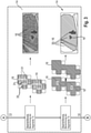
- FIGs 2 to 5 show parts of the image processing system 1 with surrounding images 7 and/or schematic detailed representations.
- the environmental images 7 are preferably digital environmental images 7.
- the number of environmental images 7 is preferably part of an image series or a video, in particular they are frames.
- the environmental images 7 are generated using an image sensor, for example using a Bayer sensor with a Bayer pixel pattern (see FIG figure 2 ).
- the images of the surroundings 7 and in particular the image sensor are made up of pixels 31 .
- Each pixel 31 has an intensity 35 .
- the intensities 35 of each pixel 31 are detected.
- the intensities 35 are preferably a measure of the light energy per area of the image sensor and per unit of time.
- each pixel 31 is in particular a monochrome pixel or a color pixel.
- color pixels have color filters applied to the surface of each pixel 31 of the image sensor.
- the image sensors of color cameras, the Bayer sensor in particular, has different types of color pixels, each type having a different color filter.
- Identical color pixels of image 7 are preferably each assigned to a color channel of image 7 .
- the number and distribution of the color channels are essentially dependent on the type of image sensor.
- the color pixels and color channels in the Bayer image sensor are divided into red, green, and blue color pixels and color channels.
- Colors can be formed from the intensities of different color pixels, with each color being convertible to a gray value.
- the intensities 35 of the individual color channels are preferably corrected in such a way that they are modeled on human vision.
- the intensities of neighboring color pixels corrected in this way are preferably summed up to form a gray value.
- the monochrome pixels of image 7 are preferably assigned to a gray channel of image 7 .
- Monochrome pixels preferably have no color filter. A filter can also be applied to them; however, this filter is then essentially uniform for all monochrome pixels and only filters out light from a non-visible light spectrum.
- Image sensors of monochrome cameras preferably have monochrome pixels.
- a variety of color cameras also have image sensors with monochrome pixels along with color pixels.
- each pixel 31 comprises multiple color channels. In this case, the pixels 31 are essentially uniform and have no color filter.
- the transferred environmental images 12 include unknown objects 30, which are preferably parts of the transferred environmental images 12 that can be visually distinguished from one another, in particular by means of edges.
- the transferred surroundings images 12 are pre-processed in a first step S1 of the image processing system 1 . At least one normalization of the transferred surroundings images 12 is carried out. At least an intensity normalization 27, a color normalization 28 and a selection of an evaluation area 29 are carried out in the transferred environmental images 12.
- the intensity normalization 27 can be carried out with at least one color or gray channel.
- at least one reference image 33 is created here, which represents, for example, intensity profiles caused by the lens or the ambient light.
- a plurality of reference images 33 are preferably generated for this purpose and superimposed to form a reference image 33 .
- the maximum intensity 35 of a pixel 31 of the reference image 33 is preferably used together with intensity curves in the reference image 33 to calculate a pixel-specific intensity correction factor for each pixel 31 .
- each pixel 31 of the transferred environmental images 12 is corrected, preferably multiplicatively, with the pixel-specific intensity correction factor.
- a reference object 34 with a known color is preferably selected in the transferred environmental images 12, in particular in a selection of transferred environmental images 12.
- the reference object 34 is preferably a painted component and/or a painted attachment 22 of the agricultural working machine 2, the exact color of which is known.
- the reference object 34 is a coiler.
- An intensity correction value is preferably determined for each color channel of the transferred image 12 and the intensities 35 of the pixels 31 of each color channel are corrected uniformly by the respective intensity correction value. The correction is preferably made by subtracting or adding the intensity correction value.
- Each intensity correction value is preferably determined by determining a difference between the measured respective intensities 35 of the color pixels assigned to the respective color channel of a reference object 34 with a known color in the transferred image 12 and the known respective intensities 35 of the color pixels assigned to the respective color channel of a reference object 34 with a known color in the transferred image 12 determined.
- the measured respective intensities 35 are determined in particular from a selection of color pixels of the reference object 34 with a known color and by forming an average from them.
- the mean value is preferably a median. Further normalizations, such as correction of lens distortions or signal adaptation of different types of image sensors, are within the scope of the invention.
- the selected evaluation area 29 can each include a section of the transferred surroundings images 12, preferably the area 9 in front.
- the length of the evaluation area 29 preferably extends in the direction of travel 11 up to a distance of less than 20 meters from the optical sensor 3.
- the length of the evaluation area 29 particularly preferably extends in the direction of travel 11 up to a distance of six meters from the optical sensor 3.
- the evaluation area 29 also preferably extends at least over the width of an attachment 22 of the agricultural working machine 2.
- the possible length and width of the evaluation area 29 are essentially dependent on the computing power of the image analysis unit 17 and a vehicle speed of the agricultural working machine 2.
- the pre-processed surroundings images 13 are segmented into segments 16 with pixels 31 of the same and/or similar color and/or intensity 35.
- a mathematical segmentation method is used for this.
- a superpixel method is used.
- a SEED superpixel method is preferably used.
- segmented surroundings images 14 are created. Edges of the objects 30 are then preferably imaged by parts of the edges of the segments 16 . Neighboring pixels 31 of the same and/or similar color and/or intensity 35 are preferably combined in the segments 16 .
- the segments 16 preferably correspond to super pixels.
- the SEED super pixel process is a super pixel process.
- the superpixel methods belong to the group of region-based methods of segmentation methods.
- superpixels grow, each starting from an initial seed point, in that pixels 31 of the same and/or similar color and/or intensity 35 are combined to form a superpixel. If edges of superpixels meet, a new seed point is selected for these superpixels, which corresponds to a new centroid of shape of the respective superpixel, and these superpixels grow again starting from the respective new seed point. Homogeneous superpixels are formed which reliably simulate the edges of the objects 30 . With the SEED superpixel method, on the other hand, the complete, renewed growth of the superpixels is avoided and only the edges of the superpixels are shifted.
- the method is faster than the previous superpixel methods or segmentation methods while at the same time having a high level of precision.
- it is within the scope of the invention to use other superpixel processes such as a SLIC superpixel process.
- other region-based methods such as a region-growing method, can also be used for segmenting.
- threshold value segmentation methods, edge-based segmentation methods or hybrid segmentation methods can also be used.
- the segments 16 are also optionally combined to form larger segments 16 and the redundancy of the segments 16 in the segmented surroundings images 14 is thereby reduced.
- the intensities 35, the color and/or the gray values of the pixels 31 of each segment 16 of the segmented surrounding images 14 are combined so that each segment 16 has uniform intensities 35, a uniform color and/or a uniform gray value.
- Adjacent segments 16 with the same or similar intensities 35, colors and/or gray values are then combined to form larger segments 16.
- each object 30 in the segmented environmental images 14 is preferably surrounded by a respective segment 16 . Edges of the segments 16 then preferably correspond to the edges of the objects 30. It is also not within the scope of the invention to merge the segments 16 since the segmentation by means of the segmentation method is already sufficient for carrying out the next step.
- FIG. 4 shows a schematic representation of a next step S3 of the image processing system 1.
- the segments 16 are classified.
- at least one segment feature 45 is calculated from each segment 16 .
- the segment features 45 are calculated from the respective intensities 35 of the pixels 31 of the respective segment 16 and/or from the gray values of the pixels 31 of the respective segment 16 .
- the segment features 45 preferably include a minimum intensity 35 of the respective segment 16, a maximum intensity 35 of the respective segment 16, a difference between the maximum and minimum intensity 35 of the respective segment 16, a histogram of the respective segment 16, a horizontal intensity gradient of the respective segment 16, a vertical intensity gradient of the respective segment 16, a histogram of the vertical and/or horizontal intensity gradient of the respective segment 16, and/or at least one mean intensity value of the respective segment 16, in particular an arithmetic mean intensity value and/or an intensity median of the respective segment 16
- Mean values other than segment feature 45 are also conceivable, such as a geometric, harmonic, quadratic and/or cubic mean, and/or weighted mean values.
- the segment features 45 preferably include a selection of segment features 45, which are calculated from a gray value matrix of the respective segment 16, the gray value matrix having a frequency of a pairing of the intensity ranges and/or the gray value ranges of two adjacent pixels 31 of the respective segment 16.
- Each intensity range and/or gray value range exists in each case a range between two intensities 35 and/or gray values.
- each intensity range and/or gray value range is of the same size and, together with the other intensity ranges and/or gray value ranges, covers a value range between the lowest and the greatest intensity 35 and/or the gray value in a segment 16 .
- the segment features 45 include a homogeneity, an energy, a correlation and/or a contrast of the gray value matrix.
- the homogeneity is a measure of a similarity of the intensity ranges and/or the gray value ranges of the neighboring pixels 31.
- the energy is a measure of a numerical concentration of specific pairings of two intensity ranges and/or gray value ranges in a segment 16.
- the correlation is a measure for a frequency of a statistical connection of certain pairings of intensity ranges and/or gray value ranges by determining variances. A small variance indicates a statistical relationship.
- the contrast is a measure of the frequency of very different pairings of the intensity ranges and/or the gray value ranges in a segment 16.
- segment features 45 preferably include a vertical position in the segmented image 14 and/or a centroid of the segment 16.
- the vertical position in the segmented image 14 refers here to pixel coordinates of the segment 16 in the two-dimensional segmented image 14.
- the centroid of the segment 16 is based on a physical center of mass.
- Other segment features 45 are conceivable.
- each segment 16 is classified into a class 18 using the at least one calculated segment feature 45 using a support vector machine, the support vector machine being a mathematical method for classifying segments 16 .
- the Support Vector Machine is an adaptive mathematical method, in particular a mathematical model, for the automatic classification of segments 16 and the formation of class boundaries 44.
- the class boundaries 44 formed in this way have the greatest possible distance from all other segments 16.
- a support vector machine with uses a one-against-all encoding. In the case of one-against-all coding, a segment 16 is assigned a number of possible classes 18 with different probabilities for a correct assignment. However, the most probable class 18 is output.
- the probability of Class assignments of several image data records 20 that can be further processed are offset against one another.
- other algorithms for the support vector machine such as a Gaussian kernel function.
- the support vector machine assigns a class 18 to each segment 16 based on the at least one calculated segment feature 45, preferably uniquely. To do this, it arranges the segments 16 into partial areas of a multi-dimensional segment feature space 47 . Different segment features 45 can be combined here. Classified environmental images 15 with classified segments 48 are thus formed from the segmented environmental images 14 .
- the Support Vector Machine is preferably trained before it is used.
- classes 18 are manually assigned to the segments 16 of segmented surroundings images 14 beforehand, preferably once at the factory.
- subsequent training of the support vector machine is also possible, preferably also during harvesting.
- Classes 18 are preferably assigned to objects 30 in a simple haptic-visual manner, for example by means of a touchscreen.
- Each class 18 is preferably assigned at least one segment feature 45 .
- Combinations of segment features 45 are preferably assigned to the classes. In each case, a single segment feature 45 and/or a combination of segment features 45 is used for the, preferably unambiguous, assignment of the respective class 18 to each segment 16.
- the support vector machine is also used to define values, limit values and/or value ranges for each class 18 each segment feature 45 set for assignment.
- a classification quality of the segment features 45 for the respective classes 18 is preferably determined in advance and used to select the most suitable segment features 45 for the support vector machine.
- the classification quality is a measure of the suitability of a segment feature 45 for an unambiguous class assignment. If the classification quality of a segment feature 45 is too low for a specific class 18, this segment feature 45 is preferably not used to assign this class 18.
- the classification quality is preferably checked by means of statistical and/or empirical tests, in particular by means of a cross-validation, a confusion matrix and/or a receiver operating characteristic curve. Further tests to determine the classification quality are conceivable.
- the support vector machine preferably uses segment features 45 with a high classification quality, in particular with the highest classification quality, for classifying the segments 16. As a result, the segments 16 are preferably classified unambiguously and reliably.
- the probabilities, in particular posterior probabilities, for a correct classification for each segment feature 45 and/or segment 16 are preferably calculated and preferably specified for each classification.
- the classifications are preferably post-processed after the classification of the segments 16. Incorrect classifications 49 and/or classifications with calculated low probabilities are thereby deleted.
- a plurality of classified environmental images 15 in direct succession are preferably compared with classified segments 48, and classifications of segments 16 that are only present in a single classified image 15 are evaluated as incorrect.
- FIG 5 shows a schematic representation of the following step S4 of the image processing system 1.
- the image processing system 1 generates a further processable image data record from the classified surroundings images 15 with the classified segments 48 by means of warping 51, stitching and/or a transfer to an occupancy grid 52 20.
- Warping 51 transforms a perspective. In this case, in particular, a perspective is changed to a bird's-eye view in accordance with a camera orientation.
- images of the surroundings 7, 15, in particular multiple optical sensors 3, in particular cameras 4, which are spatially and/or temporally linked to one another are merged into an image 7, 15 (not shown). This creates a larger image 7.15 with greater coverage of the area 8.
- the transfer to the occupancy grid 52 causes a spatial assignment of classified segments 48 and/or identified anomalies 19.
- This representation shows the spatial distances of the individual classified segments 48 and/or identified anomalies 19 to one another and to the agricultural working machine 2.
- the image data set 20 that can be further processed is preferably combined with data sets from other sensors, in particular optical sensors 3, and further processed to form a further image data set 20 that can be further processed.
- the further image data set 20 that can be further processed is then preferably used in the following. In this way, the additional image data set 20 that can be further processed can also be displayed visually and/or connected to other agricultural systems Work machine 2 are transferred.
- Other optical sensors 3 are, in particular, the radar sensor 5 and/or the laser scanner 6.
- the data output unit 21 is preferably set up to make at least one of the further-processable image data records 20 available to other systems of an agricultural working machine 2, in particular a regulation and control unit.
- the data output unit 21 is preferably designed as an interface.
- the data output unit is preferably connected to one or more systems of the agricultural working machine 2 via a CAN bus, ISO bus, or other data transmission systems, such as Bluetooth or WLAN.
- the data output unit 21 is preferably connected to the regulation and control unit 23 and/or to the display unit.
- At least one of the image datasets 20 that can be processed further can be used by the agricultural working machine 2 to identify the surroundings, in particular to identify anomalies 19 in advance 9 .
- the anomalies 19 are assigned to the classes 18 beforehand, the anomalies 19 are preferably detected and, in particular, automatically identified at the same time as the classification.
- a part or the entire environment 8 in particular the area in front of it 9 , is preferably shown on a display of the agricultural working machine 2 .
- the representation can preferably be presented as a colored image 7 of the camera 4 and/or preferably as a schematic view from above, in particular as an occupancy grid 52, with the anomalies 19 also being colored.
- the coloring is based on classes 18 and/or anomalies 19, so that the classes 18 and/or anomalies 19 can be easily distinguished.
- the classes 18 are preferably structured in a class structure 55 . It has several levels of structure.
- the classes preferably have sky, different grain types such as rapeseed and/or wheat, crop densities, various anomalies 19 and more.
- the classes 18, the associated segment features 45 and/or the class structure 55 are preferably stored in a database, which the image processing system 1, in particular the support vector machine, accesses for the classification.
- the anomalies 19 are assigned to the classes 18 . In particular, they are due to their shape, size, structure, materials, components, position, brightness, color and/or a required control behavior of the agricultural working machine 2 and/or its working elements assigned to classes 18.
- a number of classes 18 and/or anomalies 19 is preferably expandable.
- Anomalies 19 are
- the anomalies 19 include obstacles 56 and/or irregularities in the crop crop 57. Furthermore, they preferably also include crop and stubble. Irregularities in the crop stand 57 essentially include areal changes in height and/or orientation of plants in the crop stand and/or changes in the color and/or shape of the plants. In particular, irregularities in the crop 57 include laid grain 58 ( Figure 7a ), stock gaps 59 ( Figure 7b ), lanes 60 ( Figure 7c ), growth 61 ( Figure 7d ) and/or inventory edges (not shown).
- Obstacles 56 include, in particular, objects 30 with which the agricultural working machine 2, in particular its attachments 22, could collide and the agricultural working machine 2, the attachment 22 and/or its working parts could be damaged as a result. They also include unknown objects.
- Unknown objects include all objects 30 for which the Support Vector Machine could not assign any of the existing classes unequivocally, ie with a sufficiently high probability.
- this includes unknown obstacles 56 for which the support vector machine is not trained.
- obstacles 56 preferably include animals and people, which would cause injuries to the animals and/or people in the event of a collision and would also contaminate harvested crops that have already been harvested.
- obstacles 56 preferably include vehicles or devices with which the agricultural working machine 2 interacts as part of the harvesting process, for example a transport vehicle when harvested crops are being loaded onto it.
- the obstacles 56 include small, medium-sized and/or large obstacles 56.
- the obstacles 56 are preferably divided into low obstacles 62 and/or high obstacles 63, with low obstacles 62 being able to be passed in particular by lifting the attachment 22 without damaging the agricultural working machine 2 and high obstacles 63 in particular require the agricultural working machine 2 to dodge or stop.
- Low obstacles 62 include, for example, car tires, low rocks, piles of dirt, and/or small animals such as rabbits.
- High obstacles 63 include, for example, trees, large rocks, bodies of water, people, larger animals such as deer, other agricultural working machines 2 and/or masts. Other obstacles 56 are also conceivable here.
- the support vector machine is preferably trained with the corresponding anomalies 19 beforehand, in particular at the factory.
- the identified anomalies 19 are preferably displayed to the vehicle driver, in particular in a different color, and/or used to control the working elements of the agricultural working machine 2 .
- colors are assigned to the anomalies 19, preferably independently of their classification into classes. For example, all high obstacles 63 are shown in red and all low obstacles 62 are shown in orange.
- the detected objects 30 are preferably used for the, preferably autonomous or semi-autonomous, control of the agricultural working machine 2 , its attachments 22 and/or its working elements by means of the regulation and control unit 23 .
- the regulation and control unit 23 sends control signals to the respective actuators, in particular to the hydraulic cylinders of the attachment 22, to the steering and/or to the braking system.
- a visual or acoustic warning message and/or an instruction to control can be displayed to the driver of the vehicle.
- the regulation and control unit 23 is preferably set up to control the agricultural working machine 2 as a function of the anomalies 19 in such a way that damage to the agricultural working machine 2, injury to living beings, ingestion of plants that affect the crop quality of the already harvested Crops would reduce, avoided and / or a crop stock is efficiently harvested.
- the closed-loop and control unit 23 is preferably set up to control the agricultural working machine 2 in advance 9, depending on the image data set 20 that can be further processed, in such a way that the at least one Attachment 22 is raised in front of the stored grain 58 and / or the overgrowth 61.
- the regulation and control unit 23 is preferably set up to, as a function of the image data record 20 according to the invention that can be further processed, detect and identify stored grain 58 in the agricultural working machine 2 To control the apron 9 in such a way that the at least one attachment 22 is lowered in front of the laid grain 58 .
- the regulation and control unit 23 can be set up to lower the reel in order to improve the pick-up of the laid grain 58 .
- the regulation and control unit 23 is preferably also set up to control the agricultural working machine 2 in advance 9 when obstacles 56 are detected and identified, depending on the image data set 20 according to the invention that can be further processed, in such a way that the agricultural working machine 2 avoids the obstacles 56. In doing so, it avoids low obstacles 62, preferably by lifting attachments 22, in particular a cutterbar.
- the agricultural working machine 2 preferably avoids high obstacles 63 by stopping the agricultural working machine 2 and/or driving around it.
- the regulation and control unit 23 is preferably also set up to control the agricultural working machine 2 when a headland is detected and identified, depending on the image data set 20 according to the invention that can be further processed, in such a way that the agricultural working machine 2 raises the at least one attachment 22 at the headland .
- the regulation and control unit 23 is preferably also set up to control the agricultural working machine 2 when a lane 60 is detected and identified, depending on the image data set 20 according to the invention that can be further processed, such that it drives in and/or along the lane 60.
- the regulation and control unit 23 is preferably also set up to control the agricultural working machine 2 when a crop edge is detected and identified, depending on the image data set 20 according to the invention that can be further processed, such that the agricultural working machine 2 drives along the crop edge.
- the regulation and control unit 23 is preferably also set up to control the agricultural working machine 2 when living beings are detected and identified in advance 9, such that the agricultural working machine 2 stops.
Claims (22)
- Machine de travail agricole (2) incluant un système de traitement d'images (1), une unité de régulation et de commande (23), une unité de sortie de données (21) et au moins un système de génération d'images (3), le système de traitement d'images traitant une sélection des images d'environnement (7) dans une unité d'analyse d'images (17), le système de génération d'images (3) étant agencé pour générer des images d'environnement (7) et pour transmettre les images d'environnement (7) au système de traitement d'images (1), caractérisée en ce que le système de traitement d'images (1) est agencé pour,dans une première étape (S1), prétraiter les images d'environnement transmises (12) par l'intermédiaire d'au moins une normation des images d'environnement transmises (12) et d'au moins une normation d'intensité (27), une normation de couleur (28) et une sélection d'une zone d'analyse (29) dans les images d'environnement transmises (12), et, lors de la normation d'intensité (27), un facteur de correction d'intensité spécifique aux pixels est déterminé respectivement pour chaque pixel (7) au moyen d'au moins une image de référence (33), et l'intensité (35) de chaque pixel (31) des images d'environnement transmises (12) est corrigée avec le facteur de correction d'intensité spécifique aux pixels respectif,dans une autre étape (S2), segmenter les images d'environnement prétraitées (13), le système de traitement d'images (1) segmentant, dans l'autre étape (S2), les images d'environnement prétraitées (13) en segments (16) avec des pixels (31) de couleur ou d'intensité identique ou analogue (35),dans une étape suivante (S3), classifier les segments créés (16), le système de traitement d'images (1) classifiant dans l'étape suivante (S3) les segments (16) de façon à calculer d'abord à partir de chaque segment (16) respectivement au moins une caractéristique de segment (45), la au moins une caractéristique de segment (45) étant calculée à partir des intensités respectives (35) des pixels (31) du segment respectif (16) et/ou à partir des valeurs de gris des pixels (31) du segment respectif (16) et au moyen d'une machine à vecteurs de support, la machine à vecteurs de support étant un procédé mathématique pour classifier des segments (16), chaque segment (16) étant classifié dans une classe (18) au moyen de la au moins une caractéristique de segment calculée (45), et des images d'environnement classifiées (15) étant générées avec des segments classifiés (48), aux classes (18) étant associées des anomalies (19), et les anomalies (19) étant des objets (30) dans l'environnement (8) de la machine de travail agricole (2) qui ont une influence directe sur le fonctionnement de la machine de travail agricole (2),à chaque classe (18) étant associée au moins une caractéristique de segment (45), de sorte que des images classifiées (15) avec des anomalies identifiables (19) sont créées,et dans une étape suivante (S4), générer, à partir des images d'environnement classifiées (15) avec les segments classifiés (48), un ensemble de données d'images retraitable (20) au moyen d'une distorsion (51), d'un assemblage ou d'un transfert dans une grille d'occupation (52),et l'unité de régulation et de commande (23) est agencée pour commande la machine de travail agricole à l'aide de l'ensemble de données d'images retraitable (20).
- Machine de travail agricole (2) selon une des revendications précédentes, caractérisée en ce que la machine de travail agricole (2) comporte une unité d'affichage pour visualiser l'ensemble de données d'images retraitable (20) et les anomalies (19).
- Machine de travail agricole (2) selon la revendication 1, caractérisée en ce que le système de génération d'images (3) inclut au moins un capteur optique, le au moins un capteur optique incluant une camera (4), un capteur radar (5) ou un scanner à laser, la camera (4) étant conformée en caméra monochrome, en caméra infrarouge ou en caméra couleur.
- Machine de travail agricole (2) selon une des revendications précédentes, caractérisée en ce que la machine de travail agricole (2) comporte au moins un outil rapporté (22), en particulier un tablier de coupe.
- Machine de travail agricole (2) selon une des revendications précédentes, caractérisée en ce que les images d'environnement (7) détectent un environnement (8) de la machine de travail agricole (2), l'environnement (8) incluant une zone environnante, en particulier une zone d'approche (9), de la machine de travail agricole (2) et/ou des parties de la machine de travail agricole (2) elle-même.
- Machine de travail agricole (2) selon une des revendications précédentes, caractérisée en ce que, dans la première étape (S1), lors de la normation de couleur (28), une valeur de correction d'intensité est déterminée respectivement pour chaque canal de couleur des images d'environnement transmises (12), et les intensités (35) des pixels (31) de chaque canal de couleur sont corrigées uniformément selon la valeur de correction d'intensité respective, chaque valeur de correction d'intensité étant déterminée en déterminant une différence des intensités respectives mesurées (35) des pixels de couleur, associés au canal de couleur respectif, d'un objet de référence (34) avec une couleur connue dans les images d'environnement transmises (12) par rapport aux intensités respectives connues (35) des pixels de couleur, associés au canal de couleur respectif, d'un objet de référence (34) avec une couleur connue dans les images d'environnement transmises (12), les intensités respectives mesurées (35) étant déterminées en particulier à partir d'une sélection de pixels de couleur de l'objet de référence (34) avec une couleur connue et par formation d'une valeur moyenne dans l'environnement.
- Machine de travail agricole (2) selon revendication une des revendications précédentes, caractérisée en ce que la sélection de la zone d'analyse (29) des images d'environnement transmises (12) inclut respectivement une portion des images d'environnement transmises (12), la zone d'analyse (29) s'étendant en particulier jusqu'à une distance de moins de 20 mètres par rapport au capteur optique (3), en outre en particulier jusqu'à une distance de six mètres par rapport au capteur optique (3).
- Machine de travail agricole (2) selon une des revendications précédentes, caractérisée en ce que, dans l'autre étape (S2), le système de traitement d'images (1) segmente les images d'environnement prétraitées (13) i au moyen d'un procédé de superpixels, en outre en particulier au moyen d'un procédé de superpixels SEED.
- Machine de travail agricole (2) selon une des revendications précédentes, caractérisée en ce que, à l'étape suivante (S3), le système de traitement d'images (1) les caractéristiques de segments (45) incluant une intensité minimale du segment respectif (16), une intensité maximale du segment respectif (16), une différence entre l'intensité maximale et minimale (16) du segment respectif (16), un histogramme du segment respectif (16), un gradient d'intensité horizontal du segment respectif (16), un gradient d'intensité vertical du segment respectif (16), un histogramme du gradient d'intensité vertical et/ou horizontal du segment respectif (16) et/ou au moins une valeur moyenne d'intensité du segment respectif (16), en particulier une valeur moyenne arithmétique d'intensité et/ou une médiane d'intensité du segment respectif (16).
- Machine de travail agricole (2) selon une des revendications précédentes, caractérisée en ce qu'une sélection de caractéristiques de segments (16) est calculée à partir d'une matrice de valeurs de gris du segment respectif (16), en particulier une homogénéité, une énergie, une corrélation et/ou un contraste de la matrice de valeurs de gris, la matrice de valeurs de gris comportant une fréquence d'un appairage des zones d'intensité et/ou des zones de valeurs de gris de deux pixels voisins (31) du segment respectif (16), et/ou les caractéristiques de segments (45) incluant une position verticale dans l'image d'environnement segmentée (14) et/ou un centre de gravité formel du segment (16).
- Machine de travail agricole (2) selon une des revendications précédentes, caractérisée en ce que, dans l'étape suivante (S3), le système de traitement d'images (1) au moyen, à chaque classe (18) étant associée au moins une caractéristique de segment, une qualité de classification des caractéristiques de segments (45) étant déterminée au préalable pour les classes respectives (18) et utilisée pour sélectionner les caractéristiques de segments les plus appropriées (45) pour la machine à vecteurs de support, et en particulier la machine à vecteurs de support (45) utilisant des caractéristiques de segments (45) avec une qualité de classification élevée, en particulier avec la qualité de classification maximale, pour classifier les segments (16), et en particulier les probabilités d'une classification correcte étant calculées pour chaque caractéristique de segment (45) et/ou segment (16).
- Machine de travail agricole (2) selon une des revendications précédentes, caractérisée en ce que l'ensemble de données d'images retraitable (20) est réuni avec des ensembles de données d'autres capteurs, en particulier de capteurs optiques (3), et retraité en un autre ensemble de données d'images retraitable (20).
- Machine de travail agricole (2) selon une des revendications précédentes, caractérisée en ce que l'unité de sortie de données (21) est agencée pour fournir au moins un des ensembles de données d'images retraitables (20) à d'autres systèmes d'une machine de travail agricole (2, en particulier à l'unité de régulation et de commande.
- Machine de travail agricole (2) selon une des revendications précédentes, caractérisée en ce qu'au moins un des ensembles de données d'images retraitables (20) est utilisable par la machine de travail agricole (2) pour la reconnaissance de zone environnante, en particulier pour identifier des anomalies (19) dans la zone d'approche (9).
- Machine de travail agricole (2) selon une des revendications précédentes, caractérisée en ce que l'unité de régulation et de commande (23) est agencée pour commander la machine de travail agricole (2) en fonction des anomalies (19) de façon à éviter d'endommager la machine de travail agricole (2), de blesser des êtres vivants, de ramasser des plantes nuisibles à la qualité du produit récolté et/ou de façon à récolter de manière efficiente une culture à récolter.
- Machine de travail agricole (2) selon une des revendications précédentes, caractérisée en ce que l'unité de régulation et de commande (23) est agencée pour commander la machine de travail agricole (2) en fonction de l'ensemble de données d'images retraitable (20) en cas de détection et d'identification de céréale versée (58) et/ou de culture adventice (61) dans la zone d'approche (9), de façon qu'au moins un outil rapporté (22) soit relevé avant la céréale versée (58) et/ou la culture adventice (61).
- Machine de travail agricole (2) selon une des revendications précédentes, caractérisée en ce que l'unité de régulation et de commande (23) est agencée pour commander la machine de travail agricole (2) en fonction de l'ensemble de données d'images retraitable (20) en cas de détection et d'identification de céréale versée (58) dans la zone d'approche (9), de façon à abaisser le au moins un outil rapporté (22) avant la céréale versée (58).
- Machine de travail agricole (2) selon une des revendications précédentes, caractérisée en ce que l'unité de régulation et de commande (23) est agencée pour commander la machine de travail agricole (2) en fonction de l'ensemble de données d'images retraitable (20) en cas de détection et d'identification d'obstacles (56) dans la zone d'approche (9), de façon que la machine de travail agricole (2) évite les obstacles (56), en particulier en relevant des outils rapportés (22) au-dessus d'obstacles bas (62), en particulier en arrêtant la machine de travail agricole (2) et/ou en particulier en contournant des obstacles hauts (63) .
- Machine de travail agricole (2) selon une des revendications précédentes, caractérisée en ce que l'unité de régulation et de commande (23) est agencée pour commander la machine de travail agricole (2) en fonction de l'ensemble de données d'images retraitable (20) en cas de détection et d'identification d'une tournière, de façon que la machine de travail agricole (2) relève le au moins un outil rapporté (22) au niveau de la tournière.
- Machine de travail agricole (2) selon une des revendications précédentes, caractérisée en ce que l'unité de régulation et de commande (23) est agencée pour commander la machine de travail agricole (2) en fonction de l'ensemble de données d'images retraitable (20) en cas de détection et d'identification d'une trace de roulement (60), de façon qu'elle roule dans ou le long de la trace de roulement (60).
- Machine de travail agricole (2) selon une des revendications précédentes, caractérisée en ce que l'unité de régulation et de commande (23) est agencée pour commander la machine de travail agricole (2) en fonction de l'ensemble de données d'images retraitable (20) en cas de détection et d'identification d'un bord de culture, de façon à ce que la machine de travail agricole (2) roule le long du bord de culture.
- Machine de travail agricole (2) selon une des revendications précédentes, caractérisée en ce que l'unité de régulation et de commande (23) est agencée pour commander la machine de travail agricole (2) en fonction de l'ensemble de données d'images retraitable (20) en cas de détection et d'identification d'êtres vivants dans la zone d'approche (9), de façon que la machine de travail agricole (2) s'arrête.
Applications Claiming Priority (1)
| Application Number | Priority Date | Filing Date | Title |
|---|---|---|---|
| DE102016118237.0A DE102016118237A1 (de) | 2016-09-27 | 2016-09-27 | Landwirtschaftliche Arbeitsmaschine mit Bildanalysesystem |
Publications (2)
| Publication Number | Publication Date |
|---|---|
| EP3299996A1 EP3299996A1 (fr) | 2018-03-28 |
| EP3299996B1 true EP3299996B1 (fr) | 2022-03-09 |
Family
ID=58714975
Family Applications (1)
| Application Number | Title | Priority Date | Filing Date |
|---|---|---|---|
| EP17171313.4A Active EP3299996B1 (fr) | 2016-09-27 | 2017-05-16 | Machines agricoles dotées d'un système de traitement d'images |
Country Status (2)
| Country | Link |
|---|---|
| EP (1) | EP3299996B1 (fr) |
| DE (1) | DE102016118237A1 (fr) |
Cited By (2)
| Publication number | Priority date | Publication date | Assignee | Title |
|---|---|---|---|---|
| EP4173468A1 (fr) * | 2021-10-27 | 2023-05-03 | CNH Industrial Belgium NV | Système et procédé de commande de position de composant d'une moissonneuse agricole à l'aide de données d'image |
| EP4268558A1 (fr) * | 2022-04-27 | 2023-11-01 | CLAAS Selbstfahrende Erntemaschinen GmbH | Système d'assistance pour générer des plans de route pour des machines agricoles autonomes |
Families Citing this family (17)
| Publication number | Priority date | Publication date | Assignee | Title |
|---|---|---|---|---|
| DE102017122711A1 (de) | 2017-09-29 | 2019-04-04 | Claas E-Systems Kgaa Mbh & Co. Kg | Verfahren für den Betrieb einer selbstfahrenden landwirtschaftlichen Arbeitsmaschine |
| DE102017217391A1 (de) * | 2017-09-29 | 2019-04-04 | Zf Friedrichshafen Ag | Landwirtschaftliches Arbeitsfahrzeug |
| US10806079B2 (en) | 2018-02-26 | 2020-10-20 | Deere & Company | Automatic product harvesting method and control system |
| US11072368B2 (en) | 2019-01-22 | 2021-07-27 | Deere & Company | Dynamically augmented bird's-eye view |
| DE102019000792A1 (de) * | 2019-02-05 | 2020-08-06 | Horsch Leeb Application Systems Gmbh | Vorrichtung und Verfahren zum sicheren Betreiben einer autonom betreibbaren landwirtschaftlichen Maschine |
| DE102019108505A1 (de) | 2019-04-02 | 2020-10-08 | Claas E-Systems Gmbh | Landwirtschaftliche Arbeitsmaschine |
| CN114026609A (zh) * | 2019-06-28 | 2022-02-08 | 巴斯夫农化商标有限公司 | 传感器融合 |
| DE102019218187A1 (de) * | 2019-11-25 | 2021-05-27 | Robert Bosch Gmbh | Verfahren zum Bearbeiten von Pflanzen auf einem Feld, Verfahren zum Generieren von Trainingsdaten und Verfahren zum Trainieren eines neuronalen Netzes |
| DE102019218192A1 (de) * | 2019-11-25 | 2021-05-27 | Robert Bosch Gmbh | Verfahren zum Bearbeiten von Pflanzen auf einem Feld |
| CN111024710B (zh) * | 2019-12-17 | 2022-04-08 | 江苏恒宝智能系统技术有限公司 | 一种农作物异常检测系统及方法 |
| DE102020121857A1 (de) | 2020-08-20 | 2022-02-24 | Claas Selbstfahrende Erntemaschinen Gmbh | Landwirtschaftliche Arbeitsmaschine |
| DE102020132038A1 (de) | 2020-12-02 | 2022-06-02 | Deere & Company | Bedienerschnittstelle für eine autonome Maschine |
| US20220232769A1 (en) * | 2021-01-28 | 2022-07-28 | Cnh Industrial America Llc | Compact and moveable harvesting system for harvesting around obstacles in a field |
| US11870973B2 (en) | 2021-07-27 | 2024-01-09 | Deere & Company | Camera calibration tool |
| DE102021120368A1 (de) | 2021-08-05 | 2023-02-09 | Claas Selbstfahrende Erntemaschinen Gmbh | Landwirtschaftliche Maschine mit kameraüberwachter Komponente |
| GB202208926D0 (en) * | 2022-06-17 | 2022-08-10 | Agco Int Gmbh | Agricultural operation mapping |
| DE102022115392A1 (de) | 2022-06-21 | 2023-12-21 | Deere & Company | Kontrollanordnung zur selbsttätigen Steuerung einer landwirtschaftlichen Arbeitsmaschine, Arbeitsmaschine und Verfahren |
Family Cites Families (2)
| Publication number | Priority date | Publication date | Assignee | Title |
|---|---|---|---|---|
| DE102008032191A1 (de) | 2008-07-09 | 2010-01-14 | Claas Selbstfahrende Erntemaschinen Gmbh | Selbstfahrende Erntemaschine |
| US9675000B2 (en) | 2014-05-09 | 2017-06-13 | Raven Industries, Inc. | Optical flow sensing application in agricultural vehicles |
-
2016
- 2016-09-27 DE DE102016118237.0A patent/DE102016118237A1/de active Pending
-
2017
- 2017-05-16 EP EP17171313.4A patent/EP3299996B1/fr active Active
Non-Patent Citations (1)
| Title |
|---|
| IONUT GHEORGHE, WEIDONG LI, THOMAS POPHAM, KEITH J. BURNHAM: "Superpixel based semantic segmentation for assistance in varying terrain driving conditions", 1 January 2015 (2015-01-01), XP009525315, ISSN: 2194-5357, ISBN: 978-3-319-08421-3, Retrieved from the Internet <URL:https://link.springer.com/chapter/10.1007/978-3-319-08422-0_98> [retrieved on 20210201], DOI: https://doi.org/10.1007/978-3-319-08422-0_98 * |
Cited By (2)
| Publication number | Priority date | Publication date | Assignee | Title |
|---|---|---|---|---|
| EP4173468A1 (fr) * | 2021-10-27 | 2023-05-03 | CNH Industrial Belgium NV | Système et procédé de commande de position de composant d'une moissonneuse agricole à l'aide de données d'image |
| EP4268558A1 (fr) * | 2022-04-27 | 2023-11-01 | CLAAS Selbstfahrende Erntemaschinen GmbH | Système d'assistance pour générer des plans de route pour des machines agricoles autonomes |
Also Published As
| Publication number | Publication date |
|---|---|
| EP3299996A1 (fr) | 2018-03-28 |
| DE102016118237A1 (de) | 2018-03-29 |
Similar Documents
| Publication | Publication Date | Title |
|---|---|---|
| EP3299996B1 (fr) | Machines agricoles dotées d'un système de traitement d'images | |
| EP3299995A1 (fr) | Système d'analyse d'images pour machines agricoles | |
| EP3718387B1 (fr) | Machine de travail agricole | |
| EP1529428B1 (fr) | Procédé et système pour la direction automatique d'une machine agricole | |
| EP3300019B1 (fr) | Surveillance d'écoulement de produit dans un dispositif de collecte de récolte | |
| EP2286653B1 (fr) | Plateforme mobile autonome destinée au traitement de surface | |
| DE69814847T2 (de) | Agrar-erntemaschine mit roboter-kontrolle | |
| DE102014206704B4 (de) | Aktualisierung der kalibrierung einer verkehrskamera unter verwendung einer szenenanalyse | |
| EP3782467B1 (fr) | Procédé d'identification des mauvaises herbes dans un rang défini de plantes d'une surface agricole | |
| DE202017007481U1 (de) | System zur Überwachung von Nutzpflanzen | |
| DE102013205854B4 (de) | Verfahren zum Detektieren eines freien Pfads mittels temporärer Koherenz | |
| WO2020182564A1 (fr) | Système d'aide au pilotage basé sur la vision pour des véhicules terrestres | |
| DE102016209437A1 (de) | Selbsttätiges Lenksystem zur Führung eines landwirtschaftlichen Fahrzeugs über ein Feld und entsprechendes Verfahren | |
| EP4088223A1 (fr) | Procédé de génération d'une pluralité d'images annotées | |
| DE102018120756A1 (de) | Mobile Analyse- und Bearbeitungsvorrichtung, Verfahren und Trägersystem | |
| DE102019218192A1 (de) | Verfahren zum Bearbeiten von Pflanzen auf einem Feld | |
| EP3663881B1 (fr) | Procédé de commande d'un véhicule autonome en fonction des vecteurs de mouvement estimés | |
| EP2996327B1 (fr) | Systeme de vue environnante pour vehicules dote d'appareils de montage | |
| EP4064819B1 (fr) | Procédé de traitement de plantes dans un champ, de génération de données d'apprentissage et d'entraînement d'un réseau de neurones | |
| EP3663800B1 (fr) | Procédé de détection d'objet à l'aide d'une camera tridimensionnelle | |
| DE102019201977A1 (de) | Verfahren zum Ermitteln eines Zustandes einer Feldfrucht-Bepflanzung und landwirtschaftliches Fahrzeug | |
| WO2020039045A1 (fr) | Système de support pourvu d'un support et d'un dispositif mobile pour le traitement du sol et/ou pour la manipulation de la flore et de la faune et procédé associé | |
| EP4324315A1 (fr) | Dispositif de détection d'andain | |
| DE102019201983A1 (de) | Verfahren zum Ermitteln eines Zustandes einer Feldfrucht-Bepflanzung und landwirtschaftliches Fahrzeug | |
| DE102019218186A1 (de) | Verfahren zum Bearbeiten von Pflanzen auf einem Feld |
Legal Events
| Date | Code | Title | Description |
|---|---|---|---|
| PUAI | Public reference made under article 153(3) epc to a published international application that has entered the european phase |
Free format text: ORIGINAL CODE: 0009012 |
|
| STAA | Information on the status of an ep patent application or granted ep patent |
Free format text: STATUS: THE APPLICATION HAS BEEN PUBLISHED |
|
| AK | Designated contracting states |
Kind code of ref document: A1 Designated state(s): AL AT BE BG CH CY CZ DE DK EE ES FI FR GB GR HR HU IE IS IT LI LT LU LV MC MK MT NL NO PL PT RO RS SE SI SK SM TR |
|
| AX | Request for extension of the european patent |
Extension state: BA ME |
|
| STAA | Information on the status of an ep patent application or granted ep patent |
Free format text: STATUS: REQUEST FOR EXAMINATION WAS MADE |
|
| 17P | Request for examination filed |
Effective date: 20180928 |
|
| RBV | Designated contracting states (corrected) |
Designated state(s): AL AT BE BG CH CY CZ DE DK EE ES FI FR GB GR HR HU IE IS IT LI LT LU LV MC MK MT NL NO PL PT RO RS SE SI SK SM TR |
|
| STAA | Information on the status of an ep patent application or granted ep patent |
Free format text: STATUS: EXAMINATION IS IN PROGRESS |
|
| 17Q | First examination report despatched |
Effective date: 20190313 |
|
| STAA | Information on the status of an ep patent application or granted ep patent |
Free format text: STATUS: EXAMINATION IS IN PROGRESS |
|
| RIC1 | Information provided on ipc code assigned before grant |
Ipc: A01B 79/00 20060101ALN20210908BHEP Ipc: G06K 9/62 20060101ALN20210908BHEP Ipc: G06T 7/11 20170101ALN20210908BHEP Ipc: A01B 69/04 20060101ALI20210908BHEP Ipc: G06K 9/00 20060101AFI20210908BHEP |
|
| GRAP | Despatch of communication of intention to grant a patent |
Free format text: ORIGINAL CODE: EPIDOSNIGR1 |
|
| STAA | Information on the status of an ep patent application or granted ep patent |
Free format text: STATUS: GRANT OF PATENT IS INTENDED |
|
| RIC1 | Information provided on ipc code assigned before grant |
Ipc: A01B 79/00 20060101ALN20210917BHEP Ipc: G06K 9/62 20060101ALN20210917BHEP Ipc: G06T 7/11 20170101ALN20210917BHEP Ipc: A01B 69/04 20060101ALI20210917BHEP Ipc: G06K 9/00 20060101AFI20210917BHEP |
|
| RIC1 | Information provided on ipc code assigned before grant |
Ipc: A01B 79/00 20060101ALN20211006BHEP Ipc: G06K 9/62 20060101ALN20211006BHEP Ipc: G06T 7/11 20170101ALN20211006BHEP Ipc: A01B 69/04 20060101ALI20211006BHEP Ipc: G06K 9/00 20060101AFI20211006BHEP |
|
| INTG | Intention to grant announced |
Effective date: 20211021 |
|
| GRAS | Grant fee paid |
Free format text: ORIGINAL CODE: EPIDOSNIGR3 |
|
| GRAA | (expected) grant |
Free format text: ORIGINAL CODE: 0009210 |
|
| STAA | Information on the status of an ep patent application or granted ep patent |
Free format text: STATUS: THE PATENT HAS BEEN GRANTED |
|
| AK | Designated contracting states |
Kind code of ref document: B1 Designated state(s): AL AT BE BG CH CY CZ DE DK EE ES FI FR GB GR HR HU IE IS IT LI LT LU LV MC MK MT NL NO PL PT RO RS SE SI SK SM TR |
|
| REG | Reference to a national code |
Ref country code: CH Ref legal event code: EP Ref country code: AT Ref legal event code: REF Ref document number: 1474776 Country of ref document: AT Kind code of ref document: T Effective date: 20220315 |
|
| REG | Reference to a national code |
Ref country code: IE Ref legal event code: FG4D Free format text: LANGUAGE OF EP DOCUMENT: GERMAN |
|
| REG | Reference to a national code |
Ref country code: DE Ref legal event code: R096 Ref document number: 502017012725 Country of ref document: DE |
|
| REG | Reference to a national code |
Ref country code: LT Ref legal event code: MG9D |
|
| REG | Reference to a national code |
Ref country code: NL Ref legal event code: MP Effective date: 20220309 |
|
| PG25 | Lapsed in a contracting state [announced via postgrant information from national office to epo] |
Ref country code: SE Free format text: LAPSE BECAUSE OF FAILURE TO SUBMIT A TRANSLATION OF THE DESCRIPTION OR TO PAY THE FEE WITHIN THE PRESCRIBED TIME-LIMIT Effective date: 20220309 Ref country code: RS Free format text: LAPSE BECAUSE OF FAILURE TO SUBMIT A TRANSLATION OF THE DESCRIPTION OR TO PAY THE FEE WITHIN THE PRESCRIBED TIME-LIMIT Effective date: 20220309 Ref country code: NO Free format text: LAPSE BECAUSE OF FAILURE TO SUBMIT A TRANSLATION OF THE DESCRIPTION OR TO PAY THE FEE WITHIN THE PRESCRIBED TIME-LIMIT Effective date: 20220609 Ref country code: LT Free format text: LAPSE BECAUSE OF FAILURE TO SUBMIT A TRANSLATION OF THE DESCRIPTION OR TO PAY THE FEE WITHIN THE PRESCRIBED TIME-LIMIT Effective date: 20220309 Ref country code: HR Free format text: LAPSE BECAUSE OF FAILURE TO SUBMIT A TRANSLATION OF THE DESCRIPTION OR TO PAY THE FEE WITHIN THE PRESCRIBED TIME-LIMIT Effective date: 20220309 Ref country code: BG Free format text: LAPSE BECAUSE OF FAILURE TO SUBMIT A TRANSLATION OF THE DESCRIPTION OR TO PAY THE FEE WITHIN THE PRESCRIBED TIME-LIMIT Effective date: 20220609 |
|
| PG25 | Lapsed in a contracting state [announced via postgrant information from national office to epo] |
Ref country code: LV Free format text: LAPSE BECAUSE OF FAILURE TO SUBMIT A TRANSLATION OF THE DESCRIPTION OR TO PAY THE FEE WITHIN THE PRESCRIBED TIME-LIMIT Effective date: 20220309 Ref country code: GR Free format text: LAPSE BECAUSE OF FAILURE TO SUBMIT A TRANSLATION OF THE DESCRIPTION OR TO PAY THE FEE WITHIN THE PRESCRIBED TIME-LIMIT Effective date: 20220610 Ref country code: FI Free format text: LAPSE BECAUSE OF FAILURE TO SUBMIT A TRANSLATION OF THE DESCRIPTION OR TO PAY THE FEE WITHIN THE PRESCRIBED TIME-LIMIT Effective date: 20220309 |
|
| PG25 | Lapsed in a contracting state [announced via postgrant information from national office to epo] |
Ref country code: NL Free format text: LAPSE BECAUSE OF FAILURE TO SUBMIT A TRANSLATION OF THE DESCRIPTION OR TO PAY THE FEE WITHIN THE PRESCRIBED TIME-LIMIT Effective date: 20220309 |
|
| PG25 | Lapsed in a contracting state [announced via postgrant information from national office to epo] |
Ref country code: SM Free format text: LAPSE BECAUSE OF FAILURE TO SUBMIT A TRANSLATION OF THE DESCRIPTION OR TO PAY THE FEE WITHIN THE PRESCRIBED TIME-LIMIT Effective date: 20220309 Ref country code: SK Free format text: LAPSE BECAUSE OF FAILURE TO SUBMIT A TRANSLATION OF THE DESCRIPTION OR TO PAY THE FEE WITHIN THE PRESCRIBED TIME-LIMIT Effective date: 20220309 Ref country code: RO Free format text: LAPSE BECAUSE OF FAILURE TO SUBMIT A TRANSLATION OF THE DESCRIPTION OR TO PAY THE FEE WITHIN THE PRESCRIBED TIME-LIMIT Effective date: 20220309 Ref country code: PT Free format text: LAPSE BECAUSE OF FAILURE TO SUBMIT A TRANSLATION OF THE DESCRIPTION OR TO PAY THE FEE WITHIN THE PRESCRIBED TIME-LIMIT Effective date: 20220711 Ref country code: ES Free format text: LAPSE BECAUSE OF FAILURE TO SUBMIT A TRANSLATION OF THE DESCRIPTION OR TO PAY THE FEE WITHIN THE PRESCRIBED TIME-LIMIT Effective date: 20220309 Ref country code: EE Free format text: LAPSE BECAUSE OF FAILURE TO SUBMIT A TRANSLATION OF THE DESCRIPTION OR TO PAY THE FEE WITHIN THE PRESCRIBED TIME-LIMIT Effective date: 20220309 Ref country code: CZ Free format text: LAPSE BECAUSE OF FAILURE TO SUBMIT A TRANSLATION OF THE DESCRIPTION OR TO PAY THE FEE WITHIN THE PRESCRIBED TIME-LIMIT Effective date: 20220309 |
|
| REG | Reference to a national code |
Ref country code: DE Ref legal event code: R079 Ref document number: 502017012725 Country of ref document: DE Free format text: PREVIOUS MAIN CLASS: G06K0009000000 Ipc: G06V0010000000 |
|
| PG25 | Lapsed in a contracting state [announced via postgrant information from national office to epo] |
Ref country code: PL Free format text: LAPSE BECAUSE OF FAILURE TO SUBMIT A TRANSLATION OF THE DESCRIPTION OR TO PAY THE FEE WITHIN THE PRESCRIBED TIME-LIMIT Effective date: 20220309 Ref country code: IS Free format text: LAPSE BECAUSE OF FAILURE TO SUBMIT A TRANSLATION OF THE DESCRIPTION OR TO PAY THE FEE WITHIN THE PRESCRIBED TIME-LIMIT Effective date: 20220709 Ref country code: AL Free format text: LAPSE BECAUSE OF FAILURE TO SUBMIT A TRANSLATION OF THE DESCRIPTION OR TO PAY THE FEE WITHIN THE PRESCRIBED TIME-LIMIT Effective date: 20220309 |
|
| REG | Reference to a national code |
Ref country code: DE Ref legal event code: R097 Ref document number: 502017012725 Country of ref document: DE |
|
| REG | Reference to a national code |
Ref country code: CH Ref legal event code: PL |
|
| PLBE | No opposition filed within time limit |
Free format text: ORIGINAL CODE: 0009261 |
|
| STAA | Information on the status of an ep patent application or granted ep patent |
Free format text: STATUS: NO OPPOSITION FILED WITHIN TIME LIMIT |
|
| PG25 | Lapsed in a contracting state [announced via postgrant information from national office to epo] |
Ref country code: MC Free format text: LAPSE BECAUSE OF FAILURE TO SUBMIT A TRANSLATION OF THE DESCRIPTION OR TO PAY THE FEE WITHIN THE PRESCRIBED TIME-LIMIT Effective date: 20220309 Ref country code: LU Free format text: LAPSE BECAUSE OF NON-PAYMENT OF DUE FEES Effective date: 20220516 Ref country code: LI Free format text: LAPSE BECAUSE OF NON-PAYMENT OF DUE FEES Effective date: 20220531 Ref country code: DK Free format text: LAPSE BECAUSE OF FAILURE TO SUBMIT A TRANSLATION OF THE DESCRIPTION OR TO PAY THE FEE WITHIN THE PRESCRIBED TIME-LIMIT Effective date: 20220309 Ref country code: CH Free format text: LAPSE BECAUSE OF NON-PAYMENT OF DUE FEES Effective date: 20220531 |
|
| 26N | No opposition filed |
Effective date: 20221212 |
|
| PG25 | Lapsed in a contracting state [announced via postgrant information from national office to epo] |
Ref country code: SI Free format text: LAPSE BECAUSE OF FAILURE TO SUBMIT A TRANSLATION OF THE DESCRIPTION OR TO PAY THE FEE WITHIN THE PRESCRIBED TIME-LIMIT Effective date: 20220309 |
|
| GBPC | Gb: european patent ceased through non-payment of renewal fee |
Effective date: 20220609 |
|
| PG25 | Lapsed in a contracting state [announced via postgrant information from national office to epo] |
Ref country code: IE Free format text: LAPSE BECAUSE OF NON-PAYMENT OF DUE FEES Effective date: 20220516 |
|
| PG25 | Lapsed in a contracting state [announced via postgrant information from national office to epo] |
Ref country code: GB Free format text: LAPSE BECAUSE OF NON-PAYMENT OF DUE FEES Effective date: 20220609 |
|
| P01 | Opt-out of the competence of the unified patent court (upc) registered |
Effective date: 20230516 |
|
| REG | Reference to a national code |
Ref country code: AT Ref legal event code: MM01 Ref document number: 1474776 Country of ref document: AT Kind code of ref document: T Effective date: 20220516 |
|
| PG25 | Lapsed in a contracting state [announced via postgrant information from national office to epo] |
Ref country code: IT Free format text: LAPSE BECAUSE OF FAILURE TO SUBMIT A TRANSLATION OF THE DESCRIPTION OR TO PAY THE FEE WITHIN THE PRESCRIBED TIME-LIMIT Effective date: 20220309 Ref country code: AT Free format text: LAPSE BECAUSE OF NON-PAYMENT OF DUE FEES Effective date: 20220516 |
|
| PGFP | Annual fee paid to national office [announced via postgrant information from national office to epo] |
Ref country code: FR Payment date: 20230526 Year of fee payment: 7 Ref country code: DE Payment date: 20230519 Year of fee payment: 7 |
|
| PGFP | Annual fee paid to national office [announced via postgrant information from national office to epo] |
Ref country code: BE Payment date: 20230519 Year of fee payment: 7 |
|
| PG25 | Lapsed in a contracting state [announced via postgrant information from national office to epo] |
Ref country code: HU Free format text: LAPSE BECAUSE OF FAILURE TO SUBMIT A TRANSLATION OF THE DESCRIPTION OR TO PAY THE FEE WITHIN THE PRESCRIBED TIME-LIMIT; INVALID AB INITIO Effective date: 20170516 |
|
| PG25 | Lapsed in a contracting state [announced via postgrant information from national office to epo] |
Ref country code: MK Free format text: LAPSE BECAUSE OF FAILURE TO SUBMIT A TRANSLATION OF THE DESCRIPTION OR TO PAY THE FEE WITHIN THE PRESCRIBED TIME-LIMIT Effective date: 20220309 Ref country code: CY Free format text: LAPSE BECAUSE OF FAILURE TO SUBMIT A TRANSLATION OF THE DESCRIPTION OR TO PAY THE FEE WITHIN THE PRESCRIBED TIME-LIMIT Effective date: 20220309 |