EP3299895A1 - Retaining member and image forming apparatus including same - Google Patents
Retaining member and image forming apparatus including same Download PDFInfo
- Publication number
- EP3299895A1 EP3299895A1 EP17189755.6A EP17189755A EP3299895A1 EP 3299895 A1 EP3299895 A1 EP 3299895A1 EP 17189755 A EP17189755 A EP 17189755A EP 3299895 A1 EP3299895 A1 EP 3299895A1
- Authority
- EP
- European Patent Office
- Prior art keywords
- retaining member
- circumferential portion
- inner circumferential
- shaft
- linkage
- Prior art date
- Legal status (The legal status is an assumption and is not a legal conclusion. Google has not performed a legal analysis and makes no representation as to the accuracy of the status listed.)
- Granted
Links
Images


Classifications
-
- G—PHYSICS
- G03—PHOTOGRAPHY; CINEMATOGRAPHY; ANALOGOUS TECHNIQUES USING WAVES OTHER THAN OPTICAL WAVES; ELECTROGRAPHY; HOLOGRAPHY
- G03G—ELECTROGRAPHY; ELECTROPHOTOGRAPHY; MAGNETOGRAPHY
- G03G21/00—Arrangements not provided for by groups G03G13/00 - G03G19/00, e.g. cleaning, elimination of residual charge
- G03G21/16—Mechanical means for facilitating the maintenance of the apparatus, e.g. modular arrangements
- G03G21/18—Mechanical means for facilitating the maintenance of the apparatus, e.g. modular arrangements using a processing cartridge, whereby the process cartridge comprises at least two image processing means in a single unit
- G03G21/1839—Means for handling the process cartridge in the apparatus body
- G03G21/1857—Means for handling the process cartridge in the apparatus body for transmitting mechanical drive power to the process cartridge, drive mechanisms, gears, couplings, braking mechanisms
- G03G21/186—Axial couplings
-
- G—PHYSICS
- G03—PHOTOGRAPHY; CINEMATOGRAPHY; ANALOGOUS TECHNIQUES USING WAVES OTHER THAN OPTICAL WAVES; ELECTROGRAPHY; HOLOGRAPHY
- G03G—ELECTROGRAPHY; ELECTROPHOTOGRAPHY; MAGNETOGRAPHY
- G03G21/00—Arrangements not provided for by groups G03G13/00 - G03G19/00, e.g. cleaning, elimination of residual charge
- G03G21/16—Mechanical means for facilitating the maintenance of the apparatus, e.g. modular arrangements
- G03G21/1642—Mechanical means for facilitating the maintenance of the apparatus, e.g. modular arrangements for connecting the different parts of the apparatus
- G03G21/1647—Mechanical connection means
-
- F—MECHANICAL ENGINEERING; LIGHTING; HEATING; WEAPONS; BLASTING
- F16—ENGINEERING ELEMENTS AND UNITS; GENERAL MEASURES FOR PRODUCING AND MAINTAINING EFFECTIVE FUNCTIONING OF MACHINES OR INSTALLATIONS; THERMAL INSULATION IN GENERAL
- F16B—DEVICES FOR FASTENING OR SECURING CONSTRUCTIONAL ELEMENTS OR MACHINE PARTS TOGETHER, e.g. NAILS, BOLTS, CIRCLIPS, CLAMPS, CLIPS OR WEDGES; JOINTS OR JOINTING
- F16B21/00—Means for preventing relative axial movement of a pin, spigot, shaft or the like and a member surrounding it; Stud-and-socket releasable fastenings
- F16B21/10—Means for preventing relative axial movement of a pin, spigot, shaft or the like and a member surrounding it; Stud-and-socket releasable fastenings by separate parts
- F16B21/16—Means for preventing relative axial movement of a pin, spigot, shaft or the like and a member surrounding it; Stud-and-socket releasable fastenings by separate parts with grooves or notches in the pin or shaft
- F16B21/18—Means for preventing relative axial movement of a pin, spigot, shaft or the like and a member surrounding it; Stud-and-socket releasable fastenings by separate parts with grooves or notches in the pin or shaft with circlips or like resilient retaining devices, i.e. resilient in the plane of the ring or the like; Details
- F16B21/186—Means for preventing relative axial movement of a pin, spigot, shaft or the like and a member surrounding it; Stud-and-socket releasable fastenings by separate parts with grooves or notches in the pin or shaft with circlips or like resilient retaining devices, i.e. resilient in the plane of the ring or the like; Details external, i.e. with contracting action
-
- F—MECHANICAL ENGINEERING; LIGHTING; HEATING; WEAPONS; BLASTING
- F16—ENGINEERING ELEMENTS AND UNITS; GENERAL MEASURES FOR PRODUCING AND MAINTAINING EFFECTIVE FUNCTIONING OF MACHINES OR INSTALLATIONS; THERMAL INSULATION IN GENERAL
- F16C—SHAFTS; FLEXIBLE SHAFTS; ELEMENTS OR CRANKSHAFT MECHANISMS; ROTARY BODIES OTHER THAN GEARING ELEMENTS; BEARINGS
- F16C35/00—Rigid support of bearing units; Housings, e.g. caps, covers
- F16C35/04—Rigid support of bearing units; Housings, e.g. caps, covers in the case of ball or roller bearings
- F16C35/06—Mounting or dismounting of ball or roller bearings; Fixing them onto shaft or in housing
- F16C35/063—Fixing them on the shaft
-
- G—PHYSICS
- G03—PHOTOGRAPHY; CINEMATOGRAPHY; ANALOGOUS TECHNIQUES USING WAVES OTHER THAN OPTICAL WAVES; ELECTROGRAPHY; HOLOGRAPHY
- G03G—ELECTROGRAPHY; ELECTROPHOTOGRAPHY; MAGNETOGRAPHY
- G03G15/00—Apparatus for electrographic processes using a charge pattern
- G03G15/75—Details relating to xerographic drum, band or plate, e.g. replacing, testing
- G03G15/757—Drive mechanisms for photosensitive medium, e.g. gears
-
- F—MECHANICAL ENGINEERING; LIGHTING; HEATING; WEAPONS; BLASTING
- F16—ENGINEERING ELEMENTS AND UNITS; GENERAL MEASURES FOR PRODUCING AND MAINTAINING EFFECTIVE FUNCTIONING OF MACHINES OR INSTALLATIONS; THERMAL INSULATION IN GENERAL
- F16C—SHAFTS; FLEXIBLE SHAFTS; ELEMENTS OR CRANKSHAFT MECHANISMS; ROTARY BODIES OTHER THAN GEARING ELEMENTS; BEARINGS
- F16C2226/00—Joining parts; Fastening; Assembling or mounting parts
- F16C2226/10—Force connections, e.g. clamping
- F16C2226/12—Force connections, e.g. clamping by press-fit, e.g. plug-in
-
- F—MECHANICAL ENGINEERING; LIGHTING; HEATING; WEAPONS; BLASTING
- F16—ENGINEERING ELEMENTS AND UNITS; GENERAL MEASURES FOR PRODUCING AND MAINTAINING EFFECTIVE FUNCTIONING OF MACHINES OR INSTALLATIONS; THERMAL INSULATION IN GENERAL
- F16C—SHAFTS; FLEXIBLE SHAFTS; ELEMENTS OR CRANKSHAFT MECHANISMS; ROTARY BODIES OTHER THAN GEARING ELEMENTS; BEARINGS
- F16C2324/00—Apparatus used in printing
- F16C2324/16—Printing machines
-
- G—PHYSICS
- G03—PHOTOGRAPHY; CINEMATOGRAPHY; ANALOGOUS TECHNIQUES USING WAVES OTHER THAN OPTICAL WAVES; ELECTROGRAPHY; HOLOGRAPHY
- G03G—ELECTROGRAPHY; ELECTROPHOTOGRAPHY; MAGNETOGRAPHY
- G03G2221/00—Processes not provided for by group G03G2215/00, e.g. cleaning or residual charge elimination
- G03G2221/16—Mechanical means for facilitating the maintenance of the apparatus, e.g. modular arrangements and complete machine concepts
- G03G2221/1651—Mechanical means for facilitating the maintenance of the apparatus, e.g. modular arrangements and complete machine concepts for connecting the different parts
- G03G2221/1654—Locks and means for positioning or alignment
-
- G—PHYSICS
- G03—PHOTOGRAPHY; CINEMATOGRAPHY; ANALOGOUS TECHNIQUES USING WAVES OTHER THAN OPTICAL WAVES; ELECTROGRAPHY; HOLOGRAPHY
- G03G—ELECTROGRAPHY; ELECTROPHOTOGRAPHY; MAGNETOGRAPHY
- G03G2221/00—Processes not provided for by group G03G2215/00, e.g. cleaning or residual charge elimination
- G03G2221/16—Mechanical means for facilitating the maintenance of the apparatus, e.g. modular arrangements and complete machine concepts
- G03G2221/1651—Mechanical means for facilitating the maintenance of the apparatus, e.g. modular arrangements and complete machine concepts for connecting the different parts
- G03G2221/1657—Mechanical means for facilitating the maintenance of the apparatus, e.g. modular arrangements and complete machine concepts for connecting the different parts transmitting mechanical drive power
Definitions
- the present disclosure relates to a retaining member for preventing a roller and a shaft constituting a drive unit and a gear mounted around such a roller and a shaft from coming off, and an image forming apparatus, such as a copier, a printer, a facsimile machine, and a multifunction peripheral having functions of these, which is provided with such a retaining member.
- a drive transmission mechanism composed of a gear, a shaft, and the like for transmitting a rotational driving force of a drive unit is used to transmit the rotational driving force to rotary bodies such as a photosensitive drum, a developing roller, and the like as driven members.
- a drive transmission mechanism as a method to prevent a roller, a shaft, and a gear mounted around these from coming off, there has been used a method in which a retaining ring such as an E-ring is mounted around a shaft.
- a gear retaining structure in which a gear is mounted on a fixed shaft standing on a plate-shaped member made of resin, and an elastically deformable claw-shaped projection is provided projecting from the plate-shaped member, such that a hooked portion of the claw-shaped projection engages with a peripheral edge part of the gear mounted on the fixed shaft.
- An object of the present disclosure is to provide a retaining member which can be mounted and dismounted with respect to a rotation shaft with easy operations and which is also capable of achieving space saving, and an image forming apparatus provided therewith.
- a retaining member is integrally formed of an elastically deformable material, is mounted on an end part of a shaft supported by a holding member, and prevents the shaft from coming off from the holding member or prevents a rotary body mounted around the shaft from coming off.
- the retaining member has an inner circumferential portion, an outer circumferential portion, a linkage portion, a plurality of engagement claws, and a slit.
- the inner and outer circumferential portions are ring-shaped, and the outer circumferential portion is arranged outside the inner circumferential portion in a radial direction.
- the linkage portion connects the inner circumferential portion and the outer circumferential portion to each other in the radial direction.
- the plurality of engagement claws project from a surface of the inner circumferential portion pointing in a direction of the shaft, and engage with an engagement groove formed in an outer peripheral surface of the shaft.
- the slit is formed on a side opposite from the linkage portion with a center of the inner circumferential portion located between the slit and the linkage portion, and the slit cuts the inner circumferential portion in the radial direction.
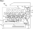
- FIG. 1 is a schematic sectional view of an image forming apparatus provided with a retaining member 41 of the present disclosure, and the image forming apparatus shown herein is a tandem-type color printer.
- a main body of a color printer 100 four image forming portions Pa, Pb, Pc, and Pd are arranged in this order from an upstream side in a sheet conveyance direction (left side in FIG. 1 ).
- the image forming portions Pa to Pd are provided corresponding to images of four different colors (cyan, magenta, yellow, and black), and sequentially form images of cyan, magenta, yellow, and black through charging, exposure, developing, and transfer processes.
- image forming portions Pa, Pb, Pc, and Pd are provided with photosensitive drums 1a, 1b, 1c, and 1d, respectively, which each carry a visible image (toner image) of a corresponding color, and further, an intermediate transfer belt 8 that rotates in a counterclockwise direction in FIG. 1 is provided adjacent to the image forming portions Pa to Pd.
- chargers 2a to 2d charge surfaces of the photosensitive drums 1a to 1d uniformly. Then, an exposure device 5 irradiates the photosensitive drums 1a to 1d with light in accordance with the image data, to thereby form an electrostatic latent image on each of the photosensitive drums 1a to 1d in accordance with the image data.
- Developing devices 3a to 3d are each filled, by toner containers 4a to 4d, with a predetermined amount of a two-component developer (which hereinafter may be referred to simply as a developer) containing a toner of a corresponding one of the four colors of cyan, magenta, yellow and black, and toners contained in the developers are supplied by the developing devices 3a to 3d, and electrostatically adhere, to the photosensitive drums 1a to 1d. Thereby, toner images are formed corresponding to the electrostatic latent images formed by the exposure to the light from the exposure device 5.
- a two-component developer which hereinafter may be referred to simply as a developer
- a transfer sheet P onto which the toner images are to be transferred is accommodated in a paper cassette 16 disposed in a lower part inside the color printer 100, and is conveyed at a predetermined timing via a sheet feeding roller 12 and a registration roller pair 13 to a nip portion (secondary transfer nip portion) between the intermediate transfer belt 8 and a secondary transfer roller 9 provided adjacent to the intermediate transfer belt 8.
- the transfer sheet P onto which the toner images have been transferred is conveyed through a sheet conveyance path 14 to a fixing portion 15.
- the transfer sheet P which has been conveyed to the fixing portion 15 is heated and pressurized by a fixing roller pair 15a, whereby the toner images are fixed on a surface of the transfer sheet P, and thereby a predetermined full-color image is formed.
- the transfer sheet P, on which the full-color image has been formed is discharged onto a discharge tray 20 by a discharge roller pair 18 as it is (or after being directed by a branching portion 17 into a reverse sheet conveyance path 21 and having an image formed on the other side).
- FIG. 2 is a sectional view of an area around the sheet conveyance path 14 and the reverse sheet conveyance path 21 in the color printer 100 shown in FIG. 1 .
- a side cover 33 constitutes a side face 102 of the color printer 100, and is rotatably supported by a pivot 33a provided in a lower part of the main body of the color printer 100.
- An inner surface of the side cover 33 constitutes one conveyance surface of the reverse sheet conveyance path 21, and a conveyance unit 35 is disposed inside the side cover 33.
- the conveyance unit 35 is supported in the main body of the color printer 100 to be rotatable about a pivot shaft 35a, and constitutes part of conveyance surfaces of the reverse sheet conveyance path 21 and the sheet conveyance path 14.
- the reverse sheet conveyance path 21 extends in an up-down direction along the side face 102 of the color printer 100 between the side cover 33 and the conveyance unit 35, and is curved into a substantially C-shape to join the sheet conveyance path 14.
- a roller 13b On an inner surface (a left-side surface of the conveyance unit 35 in FIG. 2 )of the conveyance unit 35, there are provided a roller 13b, which is one of rollers constituting the registration roller pair 13, and the secondary transfer roller 9 arranged in this order from an upstream side in the sheet conveyance direction (lower side in FIG. 2 ).
- the secondary transfer roller 9 presses a drive roller 11 with the intermediate transfer belt 8 located therebetween.
- the reverse sheet conveyance path 21 is widely exposed.
- the conveyance unit 35 is separated from a color-printer-100-main-body side and the sheet conveyance path 14 is widely exposed.
- the conveyance unit 35 comes into abutment with the color-printer-100-main-body side, and the secondary transfer roller 9 is pressed against the drive roller 11 with the intermediate transfer belt 8 located therebetween.
- FIG. 3 is an enlarged perspective view of one end side (near side in FIG. 1 ) of the secondary transfer roller 9.
- the secondary transfer roller 9 is composed of a rotation shaft 9a, which is made of metal, and a roller body 9b, which is made of rubber on an outer peripheral surface of the rotation shaft 9a, and one end part of the rotation shaft 9a is inserted through a bearing member 40 (see FIG. 7 ) disposed in a housing 35a of the conveyance unit 35.
- the bearing member 40 is, for example, a rolling bearing (bearing) having balls or rollers therein.
- the other end part (far side in FIG. 1 ) of the rotation shaft 9a is also rotatably supported by a bearing member 40.
- a retaining member 41 is mounted on an end surface of the rotation shaft 9a.
- FIG. 4 and FIG. 5 are perspective views of a retaining member 41 according to a first embodiment of the present disclosure mounted on one end of the secondary transfer roller 9, the former being as seen from a side where a surface of the retaining member 41 pointing in a direction of the rotation shaft 9a is located, and the latter being as seen from a side opposite to the side where the surface pointing in a direction of the rotation shaft 9a is located.
- FIG. 6 is a sectional view cutting the retaining member 41 of the first embodiment along the radial direction (along line AA' in FIG. 4 ).
- the retaining member 41 is a member which prevents the rotation shaft 9a from coming off from the housing 35a, and it is integrally formed of an ABS resin. It should be noted that the material of the retaining member 41 is not limited to an ABS resin, but can also be any elastically deformable material such as other synthetic resins, hard rubber, etc.
- the retaining member 41 has an inner circumferential portion 43 and an outer circumferential portion 45, which are both ring-shaped, and a linkage portion, which connects the inner circumferential portion 43 and the outer circumferential portion 45 to each other in the radial direction.
- engagement claws 43a are formed on a surface of the inner circumferential portion 43 pointing in a direction of the rotation shaft 9a.
- the engagement claws 43a are formed at three positions equally spaced from each other along a circumferential direction of the inner circumferential portion 43, leading ends of the engagement claws 43a projecting inward in the radial direction of the inner circumferential portion 43.
- a slit 43b is formed on a side opposite from the linkage portion 47 with a center of the inner circumferential portion 43 located the slit 43b and the linkage portion 47, the slit 43b cutting the inner circumferential portion 43 in the radial direction.
- the engagement claws 43a may be formed at two positions or at four or more positions along the circumferential direction of the inner circumferential portion 43, and further, the engagement claws 43a do not need to be equally spaced from each other.
- the outer circumferential portion 45 has a diameter that is substantially as large as an outer diameter of the bearing member 40 through which the rotation shaft 9a is inserted.
- a rib 45a projecting in a ring shape from a surface of the outer circumferential portion 45 pointing in a direction of the rotation shaft 9a.
- a fan-shaped recessed portion 47a is formed in a surface opposite to a surface of the linkage portion 47 pointing in a direction of the rotation shaft 9a.
- FIG. 7 is a perspective view showing how the retaining member 41 of the first embodiment is mounted on one end of the rotation shaft 9a of the secondary transfer roller 9, and FIG. 8 is a partial sectional view cutting, in an axial direction, the one end of the rotation shaft 9a on which the retaining member 41 of the first embodiment is mounted.
- FIG. 7 and FIG. 8 a description will be given of how the retaining member 41 is mounted with respect to the rotation shaft 9a.
- a diameter of a circle which passes through leading ends of the engagement claws 41a of the retaining member 41 is smaller than an outer diameter of the rotation shaft 9a, and thus the engagement claws 43a come into contact with a peripheral edge part of the tip end of the rotation shaft 9a when the retaining member 41 is pushed.
- the contact between the engagement claws 43a and the rotary shaft 9a causes a force to act on the inner circumferential portion 43 to externally expand from inside to outside in the radial direction.
- the inner circumferential portion 43 is elastically deformed to cause the slit 43b to become wide open, and the engagement claws 43a are pushed in the axial direction of the rotation shaft 9a while simultaneously being withdrawn outward in the radial direction.
- the rotation shaft 9a has a chamfered portion 50 formed on the peripheral edge part of the surface of its tip end, and thus, the engagement claws 43a are pushed along a slope of the chamfered portion 50 in the axial direction of the rotation shaft 9a.
- FIG. 9 is an enlarged view of an area near the tip end of the rotation shaft 9a shown in FIG. 8 .
- the rib 45a of the outer circumferential portion 45 is in contact with an outer peripheral edge of the bearing member 40.
- an end surface of the bearing member 40 is covered by the retaining member 41, and this makes it possible to reduce leakage of grease (lubricating oil) 60 applied between the bearing member 40 and the rotation shaft 9a.
- the retaining member 41 has an arc-shaped gap between the inner circumferential portion 43 and the outer circumferential portion 45, and that the slit 43b is formed in the inner circumferential portion 43. Hence, the retaining member 41 does not completely seal a space that includes the end surface of the bearing member 40.
- the grease 60 has a relatively high viscosity (gel), and thus it is possible to effectively reduce leakage of the grease 60 by means of the retaining member 41 of the present embodiment.
- the retaining member 41 can be easily mounted on the rotation shaft 9a by pushing it in the axial direction of the rotation shaft 9a, and can be easily removed from the rotation shaft 9a by pulling it in the axial direction of the rotation shaft 9a. Accordingly, there is no need of preparing a dedicated space in the radial direction for the detachment/attachment of the retaining member 41, and thus, it is possible to save space without spoiling the ease of assembly.
- the end surface of the bearing member 40 is covered by the retaining member 41 in a state where the retaining member 41 is mounted on the rotation shaft 9a, it is possible to reduce leakage of the grease 60 from the bearing member 40. Accordingly, even when the user touches a member that he or she can touch in a state where the side cover 33 is open, such as the secondary transfer roller 9, there is no risk of the user having his or her finger stained due to leakage of the grease 60.
- FIG. 10 is a perspective view of a retaining member 41 according to a second embodiment of the present disclosure, as seen from a side opposite to a side where a surface of the retaining member 41 pointing in a direction of the rotation shaft 9a is located
- FIG. 11 is a perspective view showing a state in which the retaining member 41 of the second embodiment is mounted on the rotation shaft 9a.
- the retaining member 41 of the present embodiment includes a handle portion 47b, which is formed to project from a peripheral edge part of the linkage portion 47 toward the side opposite to the side where the surface of the retaining member 41 pointing in a direction of the rotation shaft 9a is located.
- the configurations of the other portions of the retaining member 41 of the present embodiment are similar to those in the first embodiment.
- the handle portion 47b is held to pull the retaining member 41 outward in the radial direction (an arrow B direction in FIG. 11 ).
- the inner circumferential portion 43 is elastically deformed to cause the slit 43b to become wide open, and the engagement claws 43a are withdrawn outward in the radial direction, as a result of which the engagement between the engagement claws 43a and the engagement groove 51 becomes shallow.
- the retaining member 41 can be easily removed.
- operability in removing the retaining member 41 is improved.
- the present disclosure is not limited to the above embodiments, and various modifications are possible within the scope of the present disclosure.
- the above embodiments have dealt with cases where the retaining member 41 is mounted on the rotation shaft 9a of the secondary transfer roller 9, but the present disclosure is not limited to this, and the retaining member 41 is usable as a retaining member for rotation shafts of other rollers such as the sheet feeding roller 12, the registration roller pair 13, etc.
- the retaining member 41 can be used as a retaining member for the idle gear 73 by forming an engagement groove 51 in the fixed shaft 71 for mounting the retaining member 41.
- the present disclosure is usable in image forming apparatuses, such as copiers, printers, facsimile machines, and multifunction peripherals having functions of these.
- the use of the present disclosure provides a retaining member which can be mounted and dismounted with respect to a rotation shaft with easy operations and which is also capable of achieving space saving, and an image forming apparatus including such a retaining member.
Landscapes
- Engineering & Computer Science (AREA)
- General Engineering & Computer Science (AREA)
- Physics & Mathematics (AREA)
- General Physics & Mathematics (AREA)
- Mechanical Engineering (AREA)
- Computer Vision & Pattern Recognition (AREA)
- Electrophotography Configuration And Component (AREA)
- Rolls And Other Rotary Bodies (AREA)
- Microelectronics & Electronic Packaging (AREA)
Abstract
Description
- The present disclosure relates to a retaining member for preventing a roller and a shaft constituting a drive unit and a gear mounted around such a roller and a shaft from coming off, and an image forming apparatus, such as a copier, a printer, a facsimile machine, and a multifunction peripheral having functions of these, which is provided with such a retaining member.
- In conventional image forming apparatuses, such as copiers and printers, a drive transmission mechanism composed of a gear, a shaft, and the like for transmitting a rotational driving force of a drive unit is used to transmit the rotational driving force to rotary bodies such as a photosensitive drum, a developing roller, and the like as driven members. In such a drive transmission mechanism, as a method to prevent a roller, a shaft, and a gear mounted around these from coming off, there has been used a method in which a retaining ring such as an E-ring is mounted around a shaft.
- As for image forming apparatuses, there has been an increasing demand for compactness, and this demand puts a strict restriction on the design of the drive transmission mechanism in terms of space. In the method where the conventional retaining member such as an E-ring is used, it is necessary to mount the retaining member from a radial direction of a roller or a shaft, and this disadvantageously requires a space in the radial direction for the mounting, and makes attaching/detaching operations disadvantageously complicated. Furthermore, end parts of the roller or the shaft are exposed, and this disadvantageously allows bearing grease to leak from the end parts.
- There is also known a gear retaining structure in which a gear is mounted on a fixed shaft standing on a plate-shaped member made of resin, and an elastically deformable claw-shaped projection is provided projecting from the plate-shaped member, such that a hooked portion of the claw-shaped projection engages with a peripheral edge part of the gear mounted on the fixed shaft.
- An object of the present disclosure is to provide a retaining member which can be mounted and dismounted with respect to a rotation shaft with easy operations and which is also capable of achieving space saving, and an image forming apparatus provided therewith.
- According to one aspect of the present disclosure, a retaining member is integrally formed of an elastically deformable material, is mounted on an end part of a shaft supported by a holding member, and prevents the shaft from coming off from the holding member or prevents a rotary body mounted around the shaft from coming off. The retaining member has an inner circumferential portion, an outer circumferential portion, a linkage portion, a plurality of engagement claws, and a slit. The inner and outer circumferential portions are ring-shaped, and the outer circumferential portion is arranged outside the inner circumferential portion in a radial direction. The linkage portion connects the inner circumferential portion and the outer circumferential portion to each other in the radial direction. The plurality of engagement claws project from a surface of the inner circumferential portion pointing in a direction of the shaft, and engage with an engagement groove formed in an outer peripheral surface of the shaft. The slit is formed on a side opposite from the linkage portion with a center of the inner circumferential portion located between the slit and the linkage portion, and the slit cuts the inner circumferential portion in the radial direction.
- Further features and specific advantages of the present disclosure will become apparent from the following descriptions of preferred embodiments.
-
-
FIG. 1 is a schematic sectional view showing an overall configuration of acolor printer 100 including aretaining member 41 of the present disclosure; -
FIG. 2 is a sectional view of an area around asheet conveyance path 14 and a reversesheet conveyance path 21 in thecolor printer 100 shown inFIG. 1 ; -
FIG. 3 is an enlarged perspective view of one end side (near side inFIG. 1 ) of a secondary transfer roller 9; -
FIG. 4 is a perspective view of aretaining member 41 according to a first embodiment of the present disclosure to be mounted on one end of the secondary transfer roller 9, as seen from a side where a surface of the retainingmember 41 pointing in a direction of arotation shaft 9a is located; -
FIG. 5 is a perspective view of theretaining member 41 of the first embodiment, as seen from a side opposite to the side where the surface of the retainingmember 41 pointing in the direction of therotation shaft 9a is located; -
FIG. 6 is a sectional view cutting the retainingmember 41 along its radial direction; -
FIG. 7 is a perspective view showing how theretaining member 41 of the first embodiment is mounted on one end of therotation shaft 9a of the secondary transfer roller 9; -
FIG. 8 is a partial sectional view cutting, along its axial direction, the one end of therotation shaft 9a on which the retainingmember 41 of the first embodiment is mounted; -
FIG. 9 is an enlarged view of an area near a tip end of therotation shaft 9a shown inFIG. 8 ; -
FIG. 10 is a perspective view of aretaining member 41 according to a second embodiment of the present disclosure, as seen from a side opposite to a side where a surface of the retainingmember 41 pointing in a direction of arotation shaft 9a is located; -
FIG. 11 is a perspective view showing a state in which the retainingmember 41 of the second embodiment is mounted on therotation shaft 9a; -
FIG. 12 is a diagram showing an example in which aretaining member 41 of the present disclosure is used as a retaining mechanism for anidle gear 73 mounted on afixed shaft 71 which is fixed to aframe 70. - Hereinafter, embodiments of the present disclosure will be described with reference to the drawings.
FIG. 1 is a schematic sectional view of an image forming apparatus provided with aretaining member 41 of the present disclosure, and the image forming apparatus shown herein is a tandem-type color printer. In a main body of acolor printer 100, four image forming portions Pa, Pb, Pc, and Pd are arranged in this order from an upstream side in a sheet conveyance direction (left side inFIG. 1 ). The image forming portions Pa to Pd are provided corresponding to images of four different colors (cyan, magenta, yellow, and black), and sequentially form images of cyan, magenta, yellow, and black through charging, exposure, developing, and transfer processes. - These image forming portions Pa, Pb, Pc, and Pd are provided with
photosensitive drums 1a, 1b, 1c, and 1d, respectively, which each carry a visible image (toner image) of a corresponding color, and further, anintermediate transfer belt 8 that rotates in a counterclockwise direction inFIG. 1 is provided adjacent to the image forming portions Pa to Pd. - When image data is inputted from a host device such as a personal computer, first,
chargers 2a to 2d charge surfaces of the photosensitive drums 1a to 1d uniformly. Then, an exposure device 5 irradiates the photosensitive drums 1a to 1d with light in accordance with the image data, to thereby form an electrostatic latent image on each of the photosensitive drums 1a to 1d in accordance with the image data. Developingdevices 3a to 3d are each filled, bytoner containers 4a to 4d, with a predetermined amount of a two-component developer (which hereinafter may be referred to simply as a developer) containing a toner of a corresponding one of the four colors of cyan, magenta, yellow and black, and toners contained in the developers are supplied by the developingdevices 3a to 3d, and electrostatically adhere, to the photosensitive drums 1a to 1d. Thereby, toner images are formed corresponding to the electrostatic latent images formed by the exposure to the light from the exposure device 5. - Then, by
primary transfer rollers 6a to 6d, an electric field is applied at a predetermined transfer voltage between theprimary transfer rollers 6a to 6d and the photosensitive drums 1a to 1d, and the toner images of cyan, magenta, yellow, and black on the photosensitive drums 1a to 1d are primarily transferred onto theintermediate transfer belt 8. After the primary transfer of the toner images, residual toner and the like left on the surface of each of the photosensitive drums 1a to 1d is removed by thecleaning devices 7a to 7d. - A transfer sheet P onto which the toner images are to be transferred is accommodated in a
paper cassette 16 disposed in a lower part inside thecolor printer 100, and is conveyed at a predetermined timing via asheet feeding roller 12 and aregistration roller pair 13 to a nip portion (secondary transfer nip portion) between theintermediate transfer belt 8 and a secondary transfer roller 9 provided adjacent to theintermediate transfer belt 8. The transfer sheet P onto which the toner images have been transferred is conveyed through asheet conveyance path 14 to afixing portion 15. - The transfer sheet P which has been conveyed to the
fixing portion 15 is heated and pressurized by afixing roller pair 15a, whereby the toner images are fixed on a surface of the transfer sheet P, and thereby a predetermined full-color image is formed. The transfer sheet P, on which the full-color image has been formed, is discharged onto adischarge tray 20 by adischarge roller pair 18 as it is (or after being directed by a branchingportion 17 into a reversesheet conveyance path 21 and having an image formed on the other side). -
FIG. 2 is a sectional view of an area around thesheet conveyance path 14 and the reversesheet conveyance path 21 in thecolor printer 100 shown inFIG. 1 . Aside cover 33 constitutes aside face 102 of thecolor printer 100, and is rotatably supported by apivot 33a provided in a lower part of the main body of thecolor printer 100. An inner surface of theside cover 33 constitutes one conveyance surface of the reversesheet conveyance path 21, and aconveyance unit 35 is disposed inside theside cover 33. Theconveyance unit 35 is supported in the main body of thecolor printer 100 to be rotatable about apivot shaft 35a, and constitutes part of conveyance surfaces of the reversesheet conveyance path 21 and thesheet conveyance path 14. - The reverse
sheet conveyance path 21 extends in an up-down direction along theside face 102 of thecolor printer 100 between theside cover 33 and theconveyance unit 35, and is curved into a substantially C-shape to join thesheet conveyance path 14. On an inner surface (a left-side surface of theconveyance unit 35 inFIG. 2 )of theconveyance unit 35, there are provided aroller 13b, which is one of rollers constituting theregistration roller pair 13, and the secondary transfer roller 9 arranged in this order from an upstream side in the sheet conveyance direction (lower side inFIG. 2 ). The secondary transfer roller 9 presses adrive roller 11 with theintermediate transfer belt 8 located therebetween. - By rotating the
side cover 33 alone in an opening direction with respect to thecolor printer 100, the reversesheet conveyance path 21 is widely exposed. By rotating theside cover 33 together with theconveyance unit 35, theconveyance unit 35 is separated from a color-printer-100-main-body side and thesheet conveyance path 14 is widely exposed. On the other hand, by rotating theside cover 33 together with theconveyance unit 35 in a closing direction, theconveyance unit 35 comes into abutment with the color-printer-100-main-body side, and the secondary transfer roller 9 is pressed against thedrive roller 11 with theintermediate transfer belt 8 located therebetween. -
FIG. 3 is an enlarged perspective view of one end side (near side inFIG. 1 ) of the secondary transfer roller 9. The secondary transfer roller 9 is composed of arotation shaft 9a, which is made of metal, and aroller body 9b, which is made of rubber on an outer peripheral surface of therotation shaft 9a, and one end part of therotation shaft 9a is inserted through a bearing member 40 (seeFIG. 7 ) disposed in ahousing 35a of theconveyance unit 35. The bearingmember 40 is, for example, a rolling bearing (bearing) having balls or rollers therein. Although not illustrated here, the other end part (far side inFIG. 1 ) of therotation shaft 9a is also rotatably supported by abearing member 40. Further, aretaining member 41 is mounted on an end surface of therotation shaft 9a. -
FIG. 4 and FIG. 5 are perspective views of aretaining member 41 according to a first embodiment of the present disclosure mounted on one end of the secondary transfer roller 9, the former being as seen from a side where a surface of the retainingmember 41 pointing in a direction of therotation shaft 9a is located, and the latter being as seen from a side opposite to the side where the surface pointing in a direction of therotation shaft 9a is located.FIG. 6 is a sectional view cutting the retainingmember 41 of the first embodiment along the radial direction (along line AA' inFIG. 4 ). The retainingmember 41 is a member which prevents therotation shaft 9a from coming off from thehousing 35a, and it is integrally formed of an ABS resin. It should be noted that the material of the retainingmember 41 is not limited to an ABS resin, but can also be any elastically deformable material such as other synthetic resins, hard rubber, etc. - The retaining
member 41 has an innercircumferential portion 43 and an outercircumferential portion 45, which are both ring-shaped, and a linkage portion, which connects the innercircumferential portion 43 and the outercircumferential portion 45 to each other in the radial direction. In the innercircumferential portion 43,engagement claws 43a are formed on a surface of the innercircumferential portion 43 pointing in a direction of therotation shaft 9a. Theengagement claws 43a are formed at three positions equally spaced from each other along a circumferential direction of the innercircumferential portion 43, leading ends of theengagement claws 43a projecting inward in the radial direction of the innercircumferential portion 43. Furthermore, aslit 43b is formed on a side opposite from thelinkage portion 47 with a center of the innercircumferential portion 43 located theslit 43b and thelinkage portion 47, theslit 43b cutting the innercircumferential portion 43 in the radial direction. It should be noted that theengagement claws 43a may be formed at two positions or at four or more positions along the circumferential direction of the innercircumferential portion 43, and further, theengagement claws 43a do not need to be equally spaced from each other. - The outer
circumferential portion 45 has a diameter that is substantially as large as an outer diameter of the bearingmember 40 through which therotation shaft 9a is inserted. In the outercircumferential portion 45, along an outer peripheral edge of the outercircumferential portion 45, there is formed arib 45a projecting in a ring shape from a surface of the outercircumferential portion 45 pointing in a direction of therotation shaft 9a. In thelinkage portion 47, a fan-shaped recessedportion 47a is formed in a surface opposite to a surface of thelinkage portion 47 pointing in a direction of therotation shaft 9a. -
FIG. 7 is a perspective view showing how the retainingmember 41 of the first embodiment is mounted on one end of therotation shaft 9a of the secondary transfer roller 9, andFIG. 8 is a partial sectional view cutting, in an axial direction, the one end of therotation shaft 9a on which the retainingmember 41 of the first embodiment is mounted. With reference toFIG. 7 andFIG. 8 , a description will be given of how the retainingmember 41 is mounted with respect to therotation shaft 9a. First, therotation shaft 9a of the secondary transfer roller 9 is inserted through the bearingmember 40 disposed in thehousing 35a. Then, the retainingmember 41 is pushed in the axial direction toward a surface of a tip end of therotation shaft 9a. Here, in a state where no external force is applied to the innercircumferential portion 43, a diameter of a circle which passes through leading ends of the engagement claws 41a of the retainingmember 41 is smaller than an outer diameter of therotation shaft 9a, and thus theengagement claws 43a come into contact with a peripheral edge part of the tip end of therotation shaft 9a when the retainingmember 41 is pushed. - The contact between the
engagement claws 43a and therotary shaft 9a causes a force to act on the innercircumferential portion 43 to externally expand from inside to outside in the radial direction. As a result, the innercircumferential portion 43 is elastically deformed to cause theslit 43b to become wide open, and theengagement claws 43a are pushed in the axial direction of therotation shaft 9a while simultaneously being withdrawn outward in the radial direction. Besides, therotation shaft 9a has a chamferedportion 50 formed on the peripheral edge part of the surface of its tip end, and thus, theengagement claws 43a are pushed along a slope of the chamferedportion 50 in the axial direction of therotation shaft 9a. Then, when the retainingmember 41 is pushed by a predetermined amount and theengagement claws 43a reach anengagement groove 51, which is formed in the outer peripheral surface of therotation shaft 9a, the innercircumferential portion 43 is caused by its recovery force to shrink inward in the radial direction to cause theengagement claws 43a to engage in theengagement groove 51, and this completes the mounting of the retainingmember 41 on therotation shaft 9a. -
FIG. 9 is an enlarged view of an area near the tip end of therotation shaft 9a shown inFIG. 8 . As shown inFIG. 9 , when the retainingmember 41 is mounted on the tip end of therotation shaft 9a, therib 45a of the outercircumferential portion 45 is in contact with an outer peripheral edge of the bearingmember 40. As a result, an end surface of the bearingmember 40 is covered by the retainingmember 41, and this makes it possible to reduce leakage of grease (lubricating oil) 60 applied between the bearingmember 40 and therotation shaft 9a. - Note that the retaining
member 41 has an arc-shaped gap between the innercircumferential portion 43 and the outercircumferential portion 45, and that theslit 43b is formed in the innercircumferential portion 43. Hence, the retainingmember 41 does not completely seal a space that includes the end surface of the bearingmember 40. However, thegrease 60 has a relatively high viscosity (gel), and thus it is possible to effectively reduce leakage of thegrease 60 by means of the retainingmember 41 of the present embodiment. - To remove the retaining
member 41 from therotation shaft 9a, first, a finger is put in the recessedportion 47a formed in thelinkage portion 47, and the retainingmember 41 is pulled outward in the radial direction. As a result, the innercircumferential portion 43 is elastically deformed to cause theslit 43b to become wide open, and theengagement claws 43a are withdrawn outward in the radial direction, as a result of which the engagement between theengagement claws 43a and theengagement groove 51 becomes shallow. Then, by pulling out the retainingmember 41 in this state in the axial direction, the retainingmember 41 can be easily removed. - According to the configuration of the present embodiment, the retaining
member 41 can be easily mounted on therotation shaft 9a by pushing it in the axial direction of therotation shaft 9a, and can be easily removed from therotation shaft 9a by pulling it in the axial direction of therotation shaft 9a. Accordingly, there is no need of preparing a dedicated space in the radial direction for the detachment/attachment of the retainingmember 41, and thus, it is possible to save space without spoiling the ease of assembly. - Furthermore, since the end surface of the bearing
member 40 is covered by the retainingmember 41 in a state where the retainingmember 41 is mounted on therotation shaft 9a, it is possible to reduce leakage of thegrease 60 from the bearingmember 40. Accordingly, even when the user touches a member that he or she can touch in a state where theside cover 33 is open, such as the secondary transfer roller 9, there is no risk of the user having his or her finger stained due to leakage of thegrease 60. -
FIG. 10 is a perspective view of a retainingmember 41 according to a second embodiment of the present disclosure, as seen from a side opposite to a side where a surface of the retainingmember 41 pointing in a direction of therotation shaft 9a is located, andFIG. 11 is a perspective view showing a state in which the retainingmember 41 of the second embodiment is mounted on therotation shaft 9a. The retainingmember 41 of the present embodiment includes ahandle portion 47b, which is formed to project from a peripheral edge part of thelinkage portion 47 toward the side opposite to the side where the surface of the retainingmember 41 pointing in a direction of therotation shaft 9a is located. The configurations of the other portions of the retainingmember 41 of the present embodiment are similar to those in the first embodiment. - To remove the retaining
member 41 of the present embodiment from therotation shaft 9a, first, thehandle portion 47b is held to pull the retainingmember 41 outward in the radial direction (an arrow B direction inFIG. 11 ). As a result, the innercircumferential portion 43 is elastically deformed to cause theslit 43b to become wide open, and theengagement claws 43a are withdrawn outward in the radial direction, as a result of which the engagement between theengagement claws 43a and theengagement groove 51 becomes shallow. Then, by pulling out the retainingmember 41 in this state in the axial direction (an arrow C direction inFIG. 11 ), the retainingmember 41 can be easily removed. Thus, operability in removing the retainingmember 41 is improved. - It should be understood that the present disclosure is not limited to the above embodiments, and various modifications are possible within the scope of the present disclosure. For example, the above embodiments have dealt with cases where the retaining
member 41 is mounted on therotation shaft 9a of the secondary transfer roller 9, but the present disclosure is not limited to this, and the retainingmember 41 is usable as a retaining member for rotation shafts of other rollers such as thesheet feeding roller 12, theregistration roller pair 13, etc. Or, as shown inFIG. 12 , in a case where anidle gear 73 is mounted on a fixedshaft 71 fixed on aframe 70, the retainingmember 41 can be used as a retaining member for theidle gear 73 by forming anengagement groove 51 in the fixedshaft 71 for mounting the retainingmember 41. - The present disclosure is usable in image forming apparatuses, such as copiers, printers, facsimile machines, and multifunction peripherals having functions of these. The use of the present disclosure provides a retaining member which can be mounted and dismounted with respect to a rotation shaft with easy operations and which is also capable of achieving space saving, and an image forming apparatus including such a retaining member.
- The above embodiments of the invention as well as the appended claims and figures show multiple characterizing features of the invention in specific combinations. The skilled person will easily be able to consider further combinations or sub-combinations of these features in order to adapt the invention as defined in the claims to his specific needs.
Claims (7)
- A retaining member (41) which is mounted on an end part of a shaft (9a, 71) supported by a holding member (40, 70), and prevents the shaft (9a) from coming off from the holding member (40) or prevents a rotary body (73) mounted around the shaft (71) from coming off, the retaining member (41) comprising:an inner circumferential portion (43) which is ring-shaped;an outer circumferential portion (45) which is ring-shaped and disposed outside the inner circumferential portion (43) in a radial direction;a linkage portion (47) which connects the inner circumferential portion (43) and the outer circumferential portion (45) to each other in the radial direction;a plurality of engagement claws (43a) which project from a surface of the inner circumferential portion (43) pointing in a direction of the shaft (9a), and engage with an engagement groove (51) formed in an outer peripheral surface of the shaft (9a); anda slit (43b) which is formed on a side opposite from the linkage portion (47) with a center of the inner circumferential portion (43) located between the slit (43b) and the linkage portion (47), and cuts the inner circumferential portion (43) in the radial direction,whereinthe retaining member (41) is integrally formed of an elastically deformable material.
- The retaining member (41) of claim 1,
wherein
the plurality of engagement claws (43a) are formed on the inner circumferential portion (43) to be equally spaced from each other along a circumferential direction of the inner circumferential portion (43). - The retaining member (41) of claim 1 or 2,
wherein
a rib (45a) is formed in a ring shape along an outer peripheral edge of the outer circumferential portion (45) to project from a surface of the outer circumferential portion (45) pointing in a direction of the shaft (9a), and
the rib contacts an end surface of the holding member (40) in a state where the engagement claws (43a) are engaged in the engagement groove (51). - The retaining member (41) of any one of claims 1 to 3,
wherein
a recessed portion (47a) is formed in a surface of the linkage portion (47) opposite to a surface of the linkage portion (47) pointing in the direction of the shaft (9a). - The retaining member (41) of an one of claims 1 to 4,
wherein
the linkage portion (47) includes a handle portion (47b) formed to project from a surface of the linkage portion (47) opposite to a surface of the linkage portion (47) pointing in the direction of the shaft (9a). - The retaining member (41) of any one of claims 1 to 5,
wherein
in a state where no external force is applied to the inner circumferential portion (43), a diameter of a circle passing through leading ends of the engagement claws (43a) is smaller than an outer diameter of the shaft (9a). - An image forming apparatus (100) comprising the retaining member (41) of any one of claims 1 to 6.
Applications Claiming Priority (1)
| Application Number | Priority Date | Filing Date | Title |
|---|---|---|---|
| JP2016187944A JP6631455B2 (en) | 2016-09-27 | 2016-09-27 | Stopping member and image forming apparatus having the same |
Publications (2)
| Publication Number | Publication Date |
|---|---|
| EP3299895A1 true EP3299895A1 (en) | 2018-03-28 |
| EP3299895B1 EP3299895B1 (en) | 2019-06-19 |
Family
ID=59811153
Family Applications (1)
| Application Number | Title | Priority Date | Filing Date |
|---|---|---|---|
| EP17189755.6A Active EP3299895B1 (en) | 2016-09-27 | 2017-09-07 | Retaining member and image forming apparatus including same |
Country Status (4)
| Country | Link |
|---|---|
| US (1) | US10139775B2 (en) |
| EP (1) | EP3299895B1 (en) |
| JP (1) | JP6631455B2 (en) |
| CN (1) | CN107870546B (en) |
Families Citing this family (2)
| Publication number | Priority date | Publication date | Assignee | Title |
|---|---|---|---|---|
| JP7103062B2 (en) * | 2018-08-27 | 2022-07-20 | 京セラドキュメントソリューションズ株式会社 | Retaining member and image forming device equipped with it |
| US11402793B2 (en) * | 2019-01-10 | 2022-08-02 | Ricoh Company, Ltd. | Rotating body, member to be inserted with shaft, retaining member, and apparatus |
Citations (5)
| Publication number | Priority date | Publication date | Assignee | Title |
|---|---|---|---|---|
| US5308207A (en) * | 1992-08-24 | 1994-05-03 | Xerox Corporation | Retaining ring and shaft for securing a component thereon |
| US5463446A (en) * | 1993-05-20 | 1995-10-31 | Canon Kabushiki Kaisha | Rotary member a process cartridge and an assembling method for rolling members |
| JPH0989178A (en) * | 1995-09-27 | 1997-03-31 | Kunimori Kagaku:Kk | Pipe joint structure |
| US6072968A (en) * | 1995-06-13 | 2000-06-06 | Canon Kabushiki Kaisha | Process cartridge, assembling method for process cartridge and electrophotographic image forming apparatus |
| JP2000321836A (en) * | 1999-05-10 | 2000-11-24 | Ricoh Co Ltd | Drive unit gear retaining structure |
Family Cites Families (16)
| Publication number | Priority date | Publication date | Assignee | Title |
|---|---|---|---|---|
| ZA82756B (en) * | 1981-02-26 | 1982-12-29 | Dowty Meco Ltd | Locking devices |
| US4750878A (en) * | 1985-08-09 | 1988-06-14 | Automotive Products Plc | Retainer bushing |
| JP3140188B2 (en) * | 1992-07-03 | 2001-03-05 | 株式会社リコー | Shaft mounting parts |
| US6116809A (en) * | 1998-08-26 | 2000-09-12 | General Motors Corporation | Rotating assembly with internal retaining ring |
| JP2000120634A (en) * | 1998-10-08 | 2000-04-25 | Nidec Copal Corp | Structure to prevent motor shaft from coming off |
| DE19936708A1 (en) * | 1999-08-06 | 2001-02-08 | Bosch Gmbh Robert | Circlip |
| US6368039B2 (en) * | 1999-09-01 | 2002-04-09 | Shop Vac Corporation | Dual function retainer clip |
| US6276832B1 (en) * | 1999-09-29 | 2001-08-21 | Emerson Electric Co. | Collapsible bearing retainer |
| DE102004049710A1 (en) * | 2004-10-11 | 2006-04-13 | Springfix-Befestigungstechnik Gmbh | Connection between shaft and functional component comprises washer which fits into a peripheral groove in the shaft to hold component in place, washer having central aperture surrounded by two arms, forming horseshoe shape |
| US7280794B2 (en) * | 2005-10-26 | 2007-10-09 | Kyocera Mita Corporation | Fixing device for use in an image forming device |
| JP2008145951A (en) * | 2006-12-13 | 2008-06-26 | Canon Inc | Deflection scanning device and scanning optical device |
| CN201141403Y (en) * | 2007-12-29 | 2008-10-29 | 中国重汽集团济南技术中心有限公司 | Output double-row bearing assembly of through shaft |
| JP5306271B2 (en) * | 2010-03-26 | 2013-10-02 | 京セラドキュメントソリューションズ株式会社 | Shaft member holding mechanism, photosensitive drum unit, and image forming apparatus |
| WO2011121670A1 (en) * | 2010-03-31 | 2011-10-06 | 京セラミタ株式会社 | Rotation restricting member, mechanical device, and image forming apparatus |
| US20110283491A1 (en) * | 2010-05-20 | 2011-11-24 | Walter Ernest Ainslie | External retainer clip retainer |
| JP4846048B1 (en) * | 2010-08-24 | 2011-12-28 | シャープ株式会社 | Roller device, image forming apparatus, and roller manufacturing method |
-
2016
- 2016-09-27 JP JP2016187944A patent/JP6631455B2/en active Active
-
2017
- 2017-09-04 CN CN201710785341.8A patent/CN107870546B/en active Active
- 2017-09-05 US US15/695,637 patent/US10139775B2/en active Active
- 2017-09-07 EP EP17189755.6A patent/EP3299895B1/en active Active
Patent Citations (5)
| Publication number | Priority date | Publication date | Assignee | Title |
|---|---|---|---|---|
| US5308207A (en) * | 1992-08-24 | 1994-05-03 | Xerox Corporation | Retaining ring and shaft for securing a component thereon |
| US5463446A (en) * | 1993-05-20 | 1995-10-31 | Canon Kabushiki Kaisha | Rotary member a process cartridge and an assembling method for rolling members |
| US6072968A (en) * | 1995-06-13 | 2000-06-06 | Canon Kabushiki Kaisha | Process cartridge, assembling method for process cartridge and electrophotographic image forming apparatus |
| JPH0989178A (en) * | 1995-09-27 | 1997-03-31 | Kunimori Kagaku:Kk | Pipe joint structure |
| JP2000321836A (en) * | 1999-05-10 | 2000-11-24 | Ricoh Co Ltd | Drive unit gear retaining structure |
Also Published As
| Publication number | Publication date |
|---|---|
| JP6631455B2 (en) | 2020-01-15 |
| EP3299895B1 (en) | 2019-06-19 |
| US10139775B2 (en) | 2018-11-27 |
| JP2018054722A (en) | 2018-04-05 |
| US20180088517A1 (en) | 2018-03-29 |
| CN107870546B (en) | 2021-06-29 |
| CN107870546A (en) | 2018-04-03 |
Similar Documents
| Publication | Publication Date | Title |
|---|---|---|
| EP2738621B1 (en) | Cleaning device, intermediate transfer unit and image forming apparatus | |
| JP5156597B2 (en) | Bearing structure, cleaning device including the same, and image forming apparatus | |
| US10139775B2 (en) | Retaining member and image forming apparatus including same | |
| US9864320B2 (en) | Cleaning device and image forming apparatus therewith | |
| EP3282322B1 (en) | Image carrying member unit and image forming apparatus provided with same | |
| US9785089B2 (en) | Toner case and image forming apparatus including the same | |
| US9389535B2 (en) | Image forming apparatus with developing device having ribs | |
| US9274492B2 (en) | Cleaning mechanism, transfer belt, and image forming apparatus comprising the same | |
| JP6141790B2 (en) | Powder container and image forming apparatus | |
| JP3814524B2 (en) | Powder container, developing device including the same, and electrophotographic image forming apparatus | |
| US10635044B2 (en) | Retaining member and image forming apparatus including same | |
| EP3324243B1 (en) | Image forming unit and image forming apparatus | |
| US20120275815A1 (en) | Process cartridge and electrophotographic image forming apparatus | |
| US20190064731A1 (en) | Developing apparatus | |
| US20170168425A1 (en) | Toner case and image forming apparatus including the same | |
| JP2015129892A (en) | Attaching/detaching mechanism of charging roller, and image forming apparatus including the same | |
| JP2011128429A (en) | Shutter mechanism, cleaning device, process unit and image forming apparatus | |
| JP7841260B2 (en) | Drive transmission device and image forming apparatus | |
| JP5439391B2 (en) | Image forming unit and image forming apparatus having the same | |
| JP2012088655A (en) | Process cartridge and image forming device | |
| JP3651578B2 (en) | Image forming apparatus | |
| JP6365525B2 (en) | Image forming apparatus | |
| WO2017110181A1 (en) | Image forming device and drawer | |
| JP4257060B2 (en) | Multi-color developing device drive transmission mechanism for image forming apparatus, image forming apparatus | |
| JP2016090821A (en) | Image forming apparatus |
Legal Events
| Date | Code | Title | Description |
|---|---|---|---|
| PUAI | Public reference made under article 153(3) epc to a published international application that has entered the european phase |
Free format text: ORIGINAL CODE: 0009012 |
|
| STAA | Information on the status of an ep patent application or granted ep patent |
Free format text: STATUS: THE APPLICATION HAS BEEN PUBLISHED |
|
| AK | Designated contracting states |
Kind code of ref document: A1 Designated state(s): AL AT BE BG CH CY CZ DE DK EE ES FI FR GB GR HR HU IE IS IT LI LT LU LV MC MK MT NL NO PL PT RO RS SE SI SK SM TR |
|
| AX | Request for extension of the european patent |
Extension state: BA ME |
|
| STAA | Information on the status of an ep patent application or granted ep patent |
Free format text: STATUS: REQUEST FOR EXAMINATION WAS MADE |
|
| 17P | Request for examination filed |
Effective date: 20180815 |
|
| RBV | Designated contracting states (corrected) |
Designated state(s): AL AT BE BG CH CY CZ DE DK EE ES FI FR GB GR HR HU IE IS IT LI LT LU LV MC MK MT NL NO PL PT RO RS SE SI SK SM TR |
|
| GRAP | Despatch of communication of intention to grant a patent |
Free format text: ORIGINAL CODE: EPIDOSNIGR1 |
|
| STAA | Information on the status of an ep patent application or granted ep patent |
Free format text: STATUS: GRANT OF PATENT IS INTENDED |
|
| INTG | Intention to grant announced |
Effective date: 20190212 |
|
| GRAS | Grant fee paid |
Free format text: ORIGINAL CODE: EPIDOSNIGR3 |
|
| GRAA | (expected) grant |
Free format text: ORIGINAL CODE: 0009210 |
|
| STAA | Information on the status of an ep patent application or granted ep patent |
Free format text: STATUS: THE PATENT HAS BEEN GRANTED |
|
| AK | Designated contracting states |
Kind code of ref document: B1 Designated state(s): AL AT BE BG CH CY CZ DE DK EE ES FI FR GB GR HR HU IE IS IT LI LT LU LV MC MK MT NL NO PL PT RO RS SE SI SK SM TR |
|
| REG | Reference to a national code |
Ref country code: GB Ref legal event code: FG4D |
|
| REG | Reference to a national code |
Ref country code: CH Ref legal event code: EP |
|
| REG | Reference to a national code |
Ref country code: IE Ref legal event code: FG4D |
|
| REG | Reference to a national code |
Ref country code: AT Ref legal event code: REF Ref document number: 1146283 Country of ref document: AT Kind code of ref document: T Effective date: 20190715 |
|
| REG | Reference to a national code |
Ref country code: DE Ref legal event code: R096 Ref document number: 602017004622 Country of ref document: DE |
|
| REG | Reference to a national code |
Ref country code: NL Ref legal event code: MP Effective date: 20190619 |
|
| PG25 | Lapsed in a contracting state [announced via postgrant information from national office to epo] |
Ref country code: AL Free format text: LAPSE BECAUSE OF FAILURE TO SUBMIT A TRANSLATION OF THE DESCRIPTION OR TO PAY THE FEE WITHIN THE PRESCRIBED TIME-LIMIT Effective date: 20190619 Ref country code: SE Free format text: LAPSE BECAUSE OF FAILURE TO SUBMIT A TRANSLATION OF THE DESCRIPTION OR TO PAY THE FEE WITHIN THE PRESCRIBED TIME-LIMIT Effective date: 20190619 Ref country code: FI Free format text: LAPSE BECAUSE OF FAILURE TO SUBMIT A TRANSLATION OF THE DESCRIPTION OR TO PAY THE FEE WITHIN THE PRESCRIBED TIME-LIMIT Effective date: 20190619 Ref country code: NO Free format text: LAPSE BECAUSE OF FAILURE TO SUBMIT A TRANSLATION OF THE DESCRIPTION OR TO PAY THE FEE WITHIN THE PRESCRIBED TIME-LIMIT Effective date: 20190919 Ref country code: HR Free format text: LAPSE BECAUSE OF FAILURE TO SUBMIT A TRANSLATION OF THE DESCRIPTION OR TO PAY THE FEE WITHIN THE PRESCRIBED TIME-LIMIT Effective date: 20190619 Ref country code: LT Free format text: LAPSE BECAUSE OF FAILURE TO SUBMIT A TRANSLATION OF THE DESCRIPTION OR TO PAY THE FEE WITHIN THE PRESCRIBED TIME-LIMIT Effective date: 20190619 |
|
| REG | Reference to a national code |
Ref country code: LT Ref legal event code: MG4D |
|
| PG25 | Lapsed in a contracting state [announced via postgrant information from national office to epo] |
Ref country code: RS Free format text: LAPSE BECAUSE OF FAILURE TO SUBMIT A TRANSLATION OF THE DESCRIPTION OR TO PAY THE FEE WITHIN THE PRESCRIBED TIME-LIMIT Effective date: 20190619 Ref country code: GR Free format text: LAPSE BECAUSE OF FAILURE TO SUBMIT A TRANSLATION OF THE DESCRIPTION OR TO PAY THE FEE WITHIN THE PRESCRIBED TIME-LIMIT Effective date: 20190920 Ref country code: BG Free format text: LAPSE BECAUSE OF FAILURE TO SUBMIT A TRANSLATION OF THE DESCRIPTION OR TO PAY THE FEE WITHIN THE PRESCRIBED TIME-LIMIT Effective date: 20190919 Ref country code: LV Free format text: LAPSE BECAUSE OF FAILURE TO SUBMIT A TRANSLATION OF THE DESCRIPTION OR TO PAY THE FEE WITHIN THE PRESCRIBED TIME-LIMIT Effective date: 20190619 |
|
| REG | Reference to a national code |
Ref country code: AT Ref legal event code: MK05 Ref document number: 1146283 Country of ref document: AT Kind code of ref document: T Effective date: 20190619 |
|
| PG25 | Lapsed in a contracting state [announced via postgrant information from national office to epo] |
Ref country code: NL Free format text: LAPSE BECAUSE OF FAILURE TO SUBMIT A TRANSLATION OF THE DESCRIPTION OR TO PAY THE FEE WITHIN THE PRESCRIBED TIME-LIMIT Effective date: 20190619 Ref country code: PT Free format text: LAPSE BECAUSE OF FAILURE TO SUBMIT A TRANSLATION OF THE DESCRIPTION OR TO PAY THE FEE WITHIN THE PRESCRIBED TIME-LIMIT Effective date: 20191021 Ref country code: AT Free format text: LAPSE BECAUSE OF FAILURE TO SUBMIT A TRANSLATION OF THE DESCRIPTION OR TO PAY THE FEE WITHIN THE PRESCRIBED TIME-LIMIT Effective date: 20190619 Ref country code: EE Free format text: LAPSE BECAUSE OF FAILURE TO SUBMIT A TRANSLATION OF THE DESCRIPTION OR TO PAY THE FEE WITHIN THE PRESCRIBED TIME-LIMIT Effective date: 20190619 Ref country code: SK Free format text: LAPSE BECAUSE OF FAILURE TO SUBMIT A TRANSLATION OF THE DESCRIPTION OR TO PAY THE FEE WITHIN THE PRESCRIBED TIME-LIMIT Effective date: 20190619 Ref country code: RO Free format text: LAPSE BECAUSE OF FAILURE TO SUBMIT A TRANSLATION OF THE DESCRIPTION OR TO PAY THE FEE WITHIN THE PRESCRIBED TIME-LIMIT Effective date: 20190619 Ref country code: CZ Free format text: LAPSE BECAUSE OF FAILURE TO SUBMIT A TRANSLATION OF THE DESCRIPTION OR TO PAY THE FEE WITHIN THE PRESCRIBED TIME-LIMIT Effective date: 20190619 |
|
| PG25 | Lapsed in a contracting state [announced via postgrant information from national office to epo] |
Ref country code: IS Free format text: LAPSE BECAUSE OF FAILURE TO SUBMIT A TRANSLATION OF THE DESCRIPTION OR TO PAY THE FEE WITHIN THE PRESCRIBED TIME-LIMIT Effective date: 20191019 Ref country code: IT Free format text: LAPSE BECAUSE OF FAILURE TO SUBMIT A TRANSLATION OF THE DESCRIPTION OR TO PAY THE FEE WITHIN THE PRESCRIBED TIME-LIMIT Effective date: 20190619 Ref country code: SM Free format text: LAPSE BECAUSE OF FAILURE TO SUBMIT A TRANSLATION OF THE DESCRIPTION OR TO PAY THE FEE WITHIN THE PRESCRIBED TIME-LIMIT Effective date: 20190619 Ref country code: ES Free format text: LAPSE BECAUSE OF FAILURE TO SUBMIT A TRANSLATION OF THE DESCRIPTION OR TO PAY THE FEE WITHIN THE PRESCRIBED TIME-LIMIT Effective date: 20190619 |
|
| PG25 | Lapsed in a contracting state [announced via postgrant information from national office to epo] |
Ref country code: TR Free format text: LAPSE BECAUSE OF FAILURE TO SUBMIT A TRANSLATION OF THE DESCRIPTION OR TO PAY THE FEE WITHIN THE PRESCRIBED TIME-LIMIT Effective date: 20190619 |
|
| PG25 | Lapsed in a contracting state [announced via postgrant information from national office to epo] |
Ref country code: DK Free format text: LAPSE BECAUSE OF FAILURE TO SUBMIT A TRANSLATION OF THE DESCRIPTION OR TO PAY THE FEE WITHIN THE PRESCRIBED TIME-LIMIT Effective date: 20190619 Ref country code: PL Free format text: LAPSE BECAUSE OF FAILURE TO SUBMIT A TRANSLATION OF THE DESCRIPTION OR TO PAY THE FEE WITHIN THE PRESCRIBED TIME-LIMIT Effective date: 20190619 |
|
| PG25 | Lapsed in a contracting state [announced via postgrant information from national office to epo] |
Ref country code: MC Free format text: LAPSE BECAUSE OF FAILURE TO SUBMIT A TRANSLATION OF THE DESCRIPTION OR TO PAY THE FEE WITHIN THE PRESCRIBED TIME-LIMIT Effective date: 20190619 Ref country code: IS Free format text: LAPSE BECAUSE OF FAILURE TO SUBMIT A TRANSLATION OF THE DESCRIPTION OR TO PAY THE FEE WITHIN THE PRESCRIBED TIME-LIMIT Effective date: 20200224 |
|
| REG | Reference to a national code |
Ref country code: DE Ref legal event code: R097 Ref document number: 602017004622 Country of ref document: DE |
|
| PLBE | No opposition filed within time limit |
Free format text: ORIGINAL CODE: 0009261 |
|
| STAA | Information on the status of an ep patent application or granted ep patent |
Free format text: STATUS: NO OPPOSITION FILED WITHIN TIME LIMIT |
|
| PG2D | Information on lapse in contracting state deleted |
Ref country code: IS |
|
| PG25 | Lapsed in a contracting state [announced via postgrant information from national office to epo] |
Ref country code: LU Free format text: LAPSE BECAUSE OF NON-PAYMENT OF DUE FEES Effective date: 20190907 Ref country code: IE Free format text: LAPSE BECAUSE OF NON-PAYMENT OF DUE FEES Effective date: 20190907 |
|
| REG | Reference to a national code |
Ref country code: BE Ref legal event code: MM Effective date: 20190930 |
|
| 26N | No opposition filed |
Effective date: 20200603 |
|
| PG25 | Lapsed in a contracting state [announced via postgrant information from national office to epo] |
Ref country code: BE Free format text: LAPSE BECAUSE OF NON-PAYMENT OF DUE FEES Effective date: 20190930 Ref country code: SI Free format text: LAPSE BECAUSE OF FAILURE TO SUBMIT A TRANSLATION OF THE DESCRIPTION OR TO PAY THE FEE WITHIN THE PRESCRIBED TIME-LIMIT Effective date: 20190619 |
|
| REG | Reference to a national code |
Ref country code: CH Ref legal event code: PL |
|
| PG25 | Lapsed in a contracting state [announced via postgrant information from national office to epo] |
Ref country code: CY Free format text: LAPSE BECAUSE OF FAILURE TO SUBMIT A TRANSLATION OF THE DESCRIPTION OR TO PAY THE FEE WITHIN THE PRESCRIBED TIME-LIMIT Effective date: 20190619 |
|
| PG25 | Lapsed in a contracting state [announced via postgrant information from national office to epo] |
Ref country code: MT Free format text: LAPSE BECAUSE OF FAILURE TO SUBMIT A TRANSLATION OF THE DESCRIPTION OR TO PAY THE FEE WITHIN THE PRESCRIBED TIME-LIMIT Effective date: 20190619 Ref country code: HU Free format text: LAPSE BECAUSE OF FAILURE TO SUBMIT A TRANSLATION OF THE DESCRIPTION OR TO PAY THE FEE WITHIN THE PRESCRIBED TIME-LIMIT; INVALID AB INITIO Effective date: 20170907 |
|
| PG25 | Lapsed in a contracting state [announced via postgrant information from national office to epo] |
Ref country code: CH Free format text: LAPSE BECAUSE OF NON-PAYMENT OF DUE FEES Effective date: 20200930 Ref country code: LI Free format text: LAPSE BECAUSE OF NON-PAYMENT OF DUE FEES Effective date: 20200930 |
|
| PG25 | Lapsed in a contracting state [announced via postgrant information from national office to epo] |
Ref country code: MK Free format text: LAPSE BECAUSE OF FAILURE TO SUBMIT A TRANSLATION OF THE DESCRIPTION OR TO PAY THE FEE WITHIN THE PRESCRIBED TIME-LIMIT Effective date: 20190619 |
|
| P01 | Opt-out of the competence of the unified patent court (upc) registered |
Effective date: 20230420 |
|
| PGFP | Annual fee paid to national office [announced via postgrant information from national office to epo] |
Ref country code: DE Payment date: 20250820 Year of fee payment: 9 |
|
| PGFP | Annual fee paid to national office [announced via postgrant information from national office to epo] |
Ref country code: GB Payment date: 20250822 Year of fee payment: 9 |
|
| PGFP | Annual fee paid to national office [announced via postgrant information from national office to epo] |
Ref country code: FR Payment date: 20250820 Year of fee payment: 9 |