EP3299781A1 - Temperature measurement device and temperature measurement method - Google Patents
Temperature measurement device and temperature measurement method Download PDFInfo
- Publication number
- EP3299781A1 EP3299781A1 EP17192647.0A EP17192647A EP3299781A1 EP 3299781 A1 EP3299781 A1 EP 3299781A1 EP 17192647 A EP17192647 A EP 17192647A EP 3299781 A1 EP3299781 A1 EP 3299781A1
- Authority
- EP
- European Patent Office
- Prior art keywords
- temperature measurement
- temperature
- calibrator
- animal
- heater
- Prior art date
- Legal status (The legal status is an assumption and is not a legal conclusion. Google has not performed a legal analysis and makes no representation as to the accuracy of the status listed.)
- Granted
Links
Images




Classifications
-
- G—PHYSICS
- G01—MEASURING; TESTING
- G01J—MEASUREMENT OF INTENSITY, VELOCITY, SPECTRAL CONTENT, POLARISATION, PHASE OR PULSE CHARACTERISTICS OF INFRARED, VISIBLE OR ULTRAVIOLET LIGHT; COLORIMETRY; RADIATION PYROMETRY
- G01J5/00—Radiation pyrometry, e.g. infrared or optical thermometry
- G01J5/0022—Radiation pyrometry, e.g. infrared or optical thermometry for sensing the radiation of moving bodies
- G01J5/0025—Living bodies
-
- A—HUMAN NECESSITIES
- A01—AGRICULTURE; FORESTRY; ANIMAL HUSBANDRY; HUNTING; TRAPPING; FISHING
- A01K—ANIMAL HUSBANDRY; AVICULTURE; APICULTURE; PISCICULTURE; FISHING; REARING OR BREEDING ANIMALS, NOT OTHERWISE PROVIDED FOR; NEW BREEDS OF ANIMALS
- A01K29/00—Other apparatus for animal husbandry
- A01K29/005—Monitoring or measuring activity
-
- A—HUMAN NECESSITIES
- A01—AGRICULTURE; FORESTRY; ANIMAL HUSBANDRY; HUNTING; TRAPPING; FISHING
- A01K—ANIMAL HUSBANDRY; AVICULTURE; APICULTURE; PISCICULTURE; FISHING; REARING OR BREEDING ANIMALS, NOT OTHERWISE PROVIDED FOR; NEW BREEDS OF ANIMALS
- A01K9/00—Sucking apparatus for young stock ; Devices for mixing solid food with liquids
-
- A—HUMAN NECESSITIES
- A61—MEDICAL OR VETERINARY SCIENCE; HYGIENE
- A61B—DIAGNOSIS; SURGERY; IDENTIFICATION
- A61B5/00—Measuring for diagnostic purposes; Identification of persons
- A61B5/01—Measuring temperature of body parts ; Diagnostic temperature sensing, e.g. for malignant or inflamed tissue
- A61B5/015—By temperature mapping of body part
-
- G—PHYSICS
- G01—MEASURING; TESTING
- G01J—MEASUREMENT OF INTENSITY, VELOCITY, SPECTRAL CONTENT, POLARISATION, PHASE OR PULSE CHARACTERISTICS OF INFRARED, VISIBLE OR ULTRAVIOLET LIGHT; COLORIMETRY; RADIATION PYROMETRY
- G01J5/00—Radiation pyrometry, e.g. infrared or optical thermometry
- G01J5/52—Radiation pyrometry, e.g. infrared or optical thermometry using comparison with reference sources, e.g. disappearing-filament pyrometer
- G01J5/53—Reference sources, e.g. standard lamps; Black bodies
-
- G—PHYSICS
- G01—MEASURING; TESTING
- G01J—MEASUREMENT OF INTENSITY, VELOCITY, SPECTRAL CONTENT, POLARISATION, PHASE OR PULSE CHARACTERISTICS OF INFRARED, VISIBLE OR ULTRAVIOLET LIGHT; COLORIMETRY; RADIATION PYROMETRY
- G01J5/00—Radiation pyrometry, e.g. infrared or optical thermometry
- G01J5/80—Calibration
-
- A—HUMAN NECESSITIES
- A61—MEDICAL OR VETERINARY SCIENCE; HYGIENE
- A61B—DIAGNOSIS; SURGERY; IDENTIFICATION
- A61B2503/00—Evaluating a particular growth phase or type of persons or animals
- A61B2503/40—Animals
-
- A—HUMAN NECESSITIES
- A61—MEDICAL OR VETERINARY SCIENCE; HYGIENE
- A61B—DIAGNOSIS; SURGERY; IDENTIFICATION
- A61B2560/00—Constructional details of operational features of apparatus; Accessories for medical measuring apparatus
- A61B2560/02—Operational features
- A61B2560/0223—Operational features of calibration, e.g. protocols for calibrating sensors
- A61B2560/0238—Means for recording calibration data
-
- G—PHYSICS
- G01—MEASURING; TESTING
- G01J—MEASUREMENT OF INTENSITY, VELOCITY, SPECTRAL CONTENT, POLARISATION, PHASE OR PULSE CHARACTERISTICS OF INFRARED, VISIBLE OR ULTRAVIOLET LIGHT; COLORIMETRY; RADIATION PYROMETRY
- G01J5/00—Radiation pyrometry, e.g. infrared or optical thermometry
- G01J2005/0077—Imaging
-
- G—PHYSICS
- G01—MEASURING; TESTING
- G01J—MEASUREMENT OF INTENSITY, VELOCITY, SPECTRAL CONTENT, POLARISATION, PHASE OR PULSE CHARACTERISTICS OF INFRARED, VISIBLE OR ULTRAVIOLET LIGHT; COLORIMETRY; RADIATION PYROMETRY
- G01J5/00—Radiation pyrometry, e.g. infrared or optical thermometry
- G01J5/48—Thermography; Techniques using wholly visual means
- G01J5/485—Temperature profile
Definitions
- the present disclosure relates to a temperature measurement device and a temperature measurement method for measuring a body temperature of an animal such as livestock.
- thermometer such as a medical thermometer was required to be inserted into a rectum or a mouth and kept in a fixed time period in a fixed position. Thus, both the operator and the animal had high stress and took hard effort.
- a typical non-contact thermometer is easily influenced by an external environment such as a wind, and a measurement error (e.g., ⁇ 2°C) is also likely to occur.
- a measurement error e.g., ⁇ 2°C
- Such a measurement error occurring in measuring a body temperature causes a reduction in the reliability of health care.
- Embodiments of the present disclosure are intended to solve such a problem, and it is an object thereof is to provide a temperature measurement device and a temperature measurement method which can reduce stress and effort of an operator and a target animal, and improve the reliability of measurement of an animal's body temperature.
- the temperature measurement device of an embodiment of the present disclosure is a temperature measurement device for measuring a body temperature of an animal in a non-contact manner apart from a body of the animal, the temperature measurement device comprising: a first temperature measurement portion for measuring a temperature distribution of a predetermined range in a non-contact manner; a calibrator including at least one heater able to generate heat to a preset temperature; second temperature measurement portions provided on installation points on the calibrator, and measuring temperatures at the installation points, the installation points having different temperatures; and a controller for calibrating a first temperature measurement result obtained from a temperature distribution of a range covering an object measured by the first temperature measurement portion, by comparing a second temperature measurement result obtained from a temperature distribution of a range covering the calibrator measured by the first temperature measurement portion with temperatures of respective points of a third temperature measurement result obtained from a temperature distribution of the calibrator measured by the second temperature measurement portions.
- the calibrator might include a heat conductor conducting heat from the at least one heater, and the second temperature measurement portions might be installed on the at least one heater and at least one point of the heat conductor.
- the calibrator might include the heater including a plurality of heaters and the second temperature measurement portions might be installed on the plurality of respective heaters.
- the object might be an eye of the animal.
- the first temperature measurement portion might be attached on a feed provider for providing the animal with feed.
- the feed provider might be a nursing unit.
- the temperature measurement method of an embodiment of the present disclosure is a temperature measurement method for measuring a body temperature of an animal in a non-contact manner apart from a body of the animal, the temperature measurement method comprising: a first temperature measurement step for making a first temperature measurement portion measure a temperature distribution of a range covering an object, the first temperature measurement portion for measuring a temperature distribution of a predetermined range in a non-contact manner; a second temperature measurement step for making the first temperature measurement portion measure a temperature distribution of a range covering a calibrator including a heater able to generate heat to a preset temperature; a third temperature measurement step for making second temperature measurement portions measure a temperature distribution of the calibrator, the second temperature measurement portions being provided on installation points on the calibrator and measuring temperatures at the installation points, the installation points having different temperatures; and a calibration step for calibrating a first temperature measurement result obtained from the first temperature measurement step based on temperature differences between a second temperature measurement result obtained from the second temperature measurement step and a third temperature measurement result obtained from the third temperature measurement step.
- the first temperature measurement step might be conducted when the animal eats feed.
- An embodiment of the present disclosure including the above techniques can reduce stress and effort of an operator and a target animal, and improve the accuracy of measurement of an animal's body temperature.
- FIG. 1 is an overall view of a temperature measurement device 1 according to one embodiment of the present disclosure.
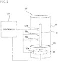
- FIG. 2 is a schematic view of a calibrator.
- the temperature measurement device 1 measures a body temperature of a target animal in a non-contact manner apart from the body thereof.
- the target animal is a calf C
- an eye E having a surface temperature indicating a high correlation with a deep body temperature is a target object.
- Most of the temperature measurement device 1 is provided on a nursing unit 2 (a feed provider) for supplying milk as feed of the calf C.
- the nursing unit 2 includes an artificial nipple 10 suckled by the calf C, a main body 11 supporting the artificial nipple 10, and a transportation pipe 12 transporting milk from a milk tank (not shown) to the main body 11.
- the main body 11 includes a cylinder 11 a having an end surface having a center supporting the artificial nipple 10, and a cone 11b conically extending from the other end of the cylinder 11a to the transportation pipe 12.
- the temperature measurement device 1 principally includes a thermography (a first temperature measurement portion) 20, a calibrator 21, and a controller 22.
- the thermography 20 and the calibrator 21 are provided on an upper portion of the cylinder 11a of the main body 11 of the nursing unit 2 via a support plate 23 which is plate-like in shape.
- the support plate 23 extends in a horizontal direction perpendicular to an extension direction of the artificial nipple 10, and has one end fixed on the upper portion of the cylinder 11a.
- the thermography 20 is a camera which, based on the amount of infrared rays emitted from a target object, obtains, in a non-contact manner, thermal images showing the temperature distribution of a predetermined range.
- the thermography 20 is provided on the support plate 23 via a rotation driver 24 which is rotatable in the horizontal direction.
- the calibrator 21 is provided on the other end of the support plate 23. Note that the thermography 20 and the calibrator 21 are positioned such that the distance between the thermography 20 and the calibrator 21 is almost equal to the distance from the thermography 20 to the eye of the calf C sucking the artificial nipple 10.
- the calibrator 21 includes a heater 30 and a rod-like heat conductor 31 coupled to the heater 30.
- the heater 30 and a plurality of points of the heat conductor 31 are provided with thermistors (second temperature measurement portions) 32a to 32d.
- the heater 30 is covered with a case 33 which is a cylindrical heat insulator having a bottom.
- the heat conductor 31 protrudes upward from an upper surface of the case 33.
- the case 33 has an outer periphery from which a cylindrical cover 34 having an opened upper portion extends upward.
- the cover 34 is made of a transparent material through which infrared rays transmit.
- the cover 34 has a windproof function to protect the heat conductor 31 from wind.
- the heater 30 is a Peltier device for example, which can generate heat to a preset temperature.
- the heat conductor 31 is a rod made of copper for example, which conducts a temperature of the heater 30.
- the heat conductor 31 has a temperature gradient such that an end portion thereof closer to the heater 30 has a highest temperature, and the temperature gradually decreases toward the other end.
- the heat conductor 31 has a length and thickness determined such that the temperature gradient is at least in the range of body temperatures of a target animal.
- the heat conductor 31 is provided with the thermistors 32b to 32d, which are generally evenly spaced in the longitudinal direction of the heat conductor 31. Then, the thermistors 32a to 32d each measure a temperature of the respective installation point. While the four thermistors are provided in this embodiment, at least one thermistor on the heater and one thermistor on the heat conductor only have to be provided. An increase in the number of thermistors leads to an increase in the accuracy. However, even if a small number of thermistors are provided, the temeprature of the respective point can be estimabed based on the temperature of heat generated by the heater and the configuration of the heat conductor.
- the thermography 20, the rotation driver 24, the heater 30, and the thermistors 32a to 32d are communicatively connected with the controller 22.
- the controller 22 is a personal computer for example, which, for example, obtains, stores, and computes the temperature distribution information measured by the thermography 20 and the temperature information measured by the thermistors 32a to 32d. Depending on the results, the controller 22 performs driving control of the rotation driver 24 and temperature setting of the heater 30.
- the controller 22 is also connected to a display 25.
- the display 25 is a flat panel display (e.g., a LCD) or a CRT display.
- the controller 22 makes the thermography 20 measure a temperature of a target object, which is the eye of the calf C drinking milk (eating feed) via the nursing unit 2.
- the controller 22 also makes the calibrator 21 calibrate the measured temperature. As such, the controller 22 performs the temperature measurement control.
- FIG. 3 is a flow chart showing a temperature measurement control routine executed by the controller of the temperature measurement device of this embodiment.
- FIG. 4A is a schematic top view showing that the thermography is oriented toward the target object.
- FIG. 4B is a schematic top view showing that the thermography is oriented toward the calibrator.
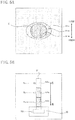
- FIG. 5A is an illustration of an example of a temperature distribution of the calf's eye.
- FIG. 5B is an illustration of an example of a temperature distribution of the calibrator. The descriptions will be provided along the flow chart in FIG. 3 , with reference to FIGS. 4 and 5 as well.
- the controller 22 starts a temperature measurement control triggered when, for example, the calf C sucks the artificial nipple 10 of the nursing unit 2.
- the controller 22 also makes the heater 30 generate heat to a given temperature in advance. This given temperature is higher than a body temperature of the calf C for example, and maintained in the range of ⁇ 0.1°C by feedback control.
- Step S1 the controller 22 makes the thermography 20 measure the temperature distribution of a range covering the eye E of the calf C (a first temperature measurement step).
- the temperature distribution measured here is hereinafter referred to as a first temperature measurement result.
- the thermography 20 is oriented toward the front direction where the artificial nipple 10 is provided, such that the eye E of the calf C is covered in the measurement range.
- a thermal image of the temperature distribution covering the eye E is obtained.
- the thermography 20 provides colors varying with the temperature level. For example, in FIG. 5A , the eye E (a range Al a) is shown in a warm color (e.g., a red).
- the surrounding area of the eye E (a range A1b) is shown in an intermediate color (e.g., a green).
- the external area of the surrounding area of the eye E (a range A1c) is shown in a cold color (e.g., a blue).
- a warmer color indicates a higher temperature
- a colder color indicates a lower temperature.
- FIGS. 5A and 5B show the temperature range in the three levels to simplify the descriptions, the temperature range is divided into more in practice.
- Step S2 the controller 22 controls the rotation driver 24 to orient the thermography 20 toward the calibrator 21. Specifically, as illustrated in FIG. 4B , the thermography is rotated clockwise in top view by 90° to face the calibrator 21.
- Step S3 the controller 22 measures the temperature distribution of a range covering the calibrator 21 (a second temperature measurement step).
- the temperature distribution measured here is hereinafter referred to as a second temperature measurement result.
- the thermography 20 is oriented toward the calibrator 21 in Step S2 such that the calibrator 21 is covered in the measurement range.
- FIG. 5B a thermal image of the temperature distribution covering the calibrator 21 is obtained.
- FIG. 5B illustrates the heat conductor 31 where a lower range A2a close to the heater 30 is shown in a warm color, a middle range A2b is shown in an intermediate color, and an upper range A2c is shown in a cold color (e.g., a blue).
- Step S4 the controller 22 makes the thermistors 32a to 32d measure temperatures (a third temperature measurement step). Specifically, as illustrated in 5B, the thermistors 32b to 32d on the heat conductor 31 measure temperatures at the respective points to obtain the temperature distribution of the heat conductor 31. The temperature distribution measured here is hereinafter referred to as a third temperature measurement result.
- the heat conductor 31 includes a lower portion provided with the thermistor 32b measuring a temperature Ta, a middle portion provided with the thermistor 32c measuring a temperature Tb, and an upper portion provided with the thermistor 32d measuring a temperature Tc. Note that the controller 22 uses a temperature T0 measured by the thermistor 32a provided on the heater 30 in order to conduct feedback control for maintaining a temperature of the heater 30.
- Step S5 the controller 22 calibrates a measurement error of the first temperature measurement result by comparing the second temperature measurement result with the temperatures of the respective points of the third temperature measurement result (a calibration step). Specifically, the temperature differences between the temperatures corresponding to ranges A2a to A2c in FIG. 5B of the second temperature measurement result and the measurement temperatures Ta to Tc corresponding to the respective ranges of the third temperature measurement result are calculated as calibration values. Then, the temperature of the range A1a of the eye which is a target object in the first temperature measurement result is calibrated with the respective calibration value to calculate a calibration temperature.
- Step S6 the controller 22 makes the display 25 display at least the calibration temperature of the eye E calibrated in Step S5, and ends the routine.
- the display 25 might also display the first temperature measurement result, the second temperature measurement result, and the third temperature measurement result, or might display the other information.
- the temperature measurement device 1 can obtain an accurate calibration temperature of the eye E by using the calibrator 21 for the temperature distribution of the first temperature measurement result covering the eye E of the calf C measured with the thermography 20.
- the measurement of a body temperature in a non-contact manner can reduce stress and effort of an operator and a target animal.
- the reliability of measurement of a body temperature with the thermography 20 can be improved.
- the calibrator 21 of this embodiment includes the heater 30 and the heat conductor 31.
- the thermography 20 measures the heat conductor 31 to obtain the second temperature measurement result.
- the thermistors 32b to 32d are provided on the heat conductor 31 to obtain the third temperature measurement result.
- the measurement result of the thermography 20 can be easily calibrated with the single heater 30.
- a temperature of the eye E of the calf C is measured to measure a body temperature of the calf C where the eye E has a surface temperature indicating a high correlation with a deep body temperature thereof.
- the measurement of a body temperature in the non-contact manner can also provide high reliability of health care.
- the temperature measurement device 1 is also provided on the nursing unit 2 (the feed provider) to measure a temperature of the eye E of the calf C drinking milk.
- the calf C is not constrained only for measurement of a body temperature, and a temperature of the eye E can be measured in a natural state. This can reduce further stress and effort of an operator and a target animal.
- the temperature measurement device and the temperature measurement method of this embodiment can reduce stress and effort of an operator and a target animal, and improve the accuracy of measurement of an animal's body temperature.
- FIG. 6 is a schematic view of a calibrator of a modified example of the present disclosure.
- the modified example of the present disclosure will be described with reference to the drawing. Note that the components except for the calibrator are the same as those of the above-described embodiment, and labeled with the same reference characters. The detailed descriptions thereof will be omitted.
- FIG. 6 illustrates a calibrator 40 including a base 41 from which a heat insulation rod 42 extends upward.
- the heat insulation rod 42 is provided with heaters 43a to 43c spaced apart.
- the heaters 43a to 43c are provided with thermistors 44a to 44c, respectively.
- a cover 45 is provided.
- the heaters 43a to 43c and the thermistors 44a to 44c are connected to a controller 22'.
- the controller 22' sets temperatures of the heaters 43a to 43c such that the temperatures are different from each other. For example, the controller 22' sets the temperature of the lower heater 43a to an upper limit of a body temperature of a target animal.
- the controller 22' also sets the temperature of the middle heater 43b to a middle body temperature of the target animal.
- the controller 22' also sets the temperature of the upper heater 43c to a lower limit of the body temperature of the target animal. Note that the number of heaters and thermistors only has to be at least two for each, but not limited to that number.
- the controller 22' After obtaining a first temperature measurement result, the controller 22' makes thermography 20 measure the temperature distribution of a range covering the calibrator 40 to obtain a second temperature measurement result. Then, the controller 22' makes the thermistor 44a to 44c measure temperatures to obtain a third temperature measurement result. As such, the controller 22' can perform the temperature measurement control similarly to the above-described embodiment.
- the calibrator 40 includes the heaters 43a to 43c having the thermistors 44a to 44c, respectively.
- the controller 22' can set and manage the temperatures of the heaters 43a to 43c. Thus, more precise calibration can be performed.
- thermography 20 measures the temperature distribution of the object (S1)
- the temperature distribution of the calibrator 21, 40 is measured (S3) and the temperature is measured by the thermistor (S4).
- the order is not limited to this one. For example, first, the measurement of the temperature distribution of the calibrator and the measurement of the temperature by the thermistor might be conducted, and then, the measurement of the temperature distribution of the object by the thermography might be conducted.
- the measurement of temperatures by the thermistors might be conducted not only at the time of Step S4 but also at a regular basis or at all times.
- the rotation driver 24 makes the thermography 20 driven and rotated to measure the temperature distribution of the eye E and the calibrator 21.
- the layout of the thermography and the calibrator is not limited to this one.
- the calibrator might be arranged such that the thermography has a measurement range convering both the target object and the calibrator. Consequently, the present disclosure can be achevied without the rotation driver, and more efficient calibration can be performed.
- the controller 22 starts the temperature measurement control triggered when the calf C sucks the artificial nipple 10 of the nursing unit 2.
- the trigger for the start of the temperature measurement control is not limited to this one.
- the temperature measurement device 1 is provided on the nursing unit 2.
- the temperature measurement device is not limited to the nursing unit.
- the temperature measurement device might be used singly, or provided on another feed provider.
- the target animal to be measured is the calf C
- the target object is the eye E
- the target animal and the target object to be measured by the temperature measurement device are not limited to these ones.
- other livestock such as a pig might be a target animal.
- An object other than the eye might be a target object as long as the target object has a surface temperature indicating a high correlation with a deep body temperature thereof.
Landscapes
- Life Sciences & Earth Sciences (AREA)
- Environmental Sciences (AREA)
- Physics & Mathematics (AREA)
- Spectroscopy & Molecular Physics (AREA)
- General Physics & Mathematics (AREA)
- Animal Husbandry (AREA)
- Biodiversity & Conservation Biology (AREA)
- Biophysics (AREA)
- Health & Medical Sciences (AREA)
- Engineering & Computer Science (AREA)
- Surgery (AREA)
- Animal Behavior & Ethology (AREA)
- General Health & Medical Sciences (AREA)
- Public Health (AREA)
- Veterinary Medicine (AREA)
- Molecular Biology (AREA)
- Medical Informatics (AREA)
- Heart & Thoracic Surgery (AREA)
- Biomedical Technology (AREA)
- Pathology (AREA)
- Measuring And Recording Apparatus For Diagnosis (AREA)
- Feeding And Watering For Cattle Raising And Animal Husbandry (AREA)
Abstract
Description
- This application claims priority to Japanese Patent Application No.
2016-188480 filed on September 27, 2016 - The present disclosure relates to a temperature measurement device and a temperature measurement method for measuring a body temperature of an animal such as livestock.
- To measure a body temperature of an animal such as cattle in a conventional way, a contact thermometer such as a medical thermometer was required to be inserted into a rectum or a mouth and kept in a fixed time period in a fixed position. Thus, both the operator and the animal had high stress and took hard effort.
- For this reason, a technique for using a non-contact thermometer such as a thermography etc. to measure a body temperature of an animal apart from the body thereof has been developed (see Japanese Unexamined Patent Publication (Japanese Translation of PCT Application) No.
2005-515872 - However, a typical non-contact thermometer is easily influenced by an external environment such as a wind, and a measurement error (e.g., ± 2°C) is also likely to occur. Such a measurement error occurring in measuring a body temperature causes a reduction in the reliability of health care.
- Embodiments of the present disclosure are intended to solve such a problem, and it is an object thereof is to provide a temperature measurement device and a temperature measurement method which can reduce stress and effort of an operator and a target animal, and improve the reliability of measurement of an animal's body temperature.
- To achieve the object, the temperature measurement device of an embodiment of the present disclosure is a temperature measurement device for measuring a body temperature of an animal in a non-contact manner apart from a body of the animal, the temperature measurement device comprising: a first temperature measurement portion for measuring a temperature distribution of a predetermined range in a non-contact manner; a calibrator including at least one heater able to generate heat to a preset temperature; second temperature measurement portions provided on installation points on the calibrator, and measuring temperatures at the installation points, the installation points having different temperatures; and a controller for calibrating a first temperature measurement result obtained from a temperature distribution of a range covering an object measured by the first temperature measurement portion, by comparing a second temperature measurement result obtained from a temperature distribution of a range covering the calibrator measured by the first temperature measurement portion with temperatures of respective points of a third temperature measurement result obtained from a temperature distribution of the calibrator measured by the second temperature measurement portions.
- In the temperature measurement device of the embodiment of the present disclosure, the calibrator might include a heat conductor conducting heat from the at least one heater, and the second temperature measurement portions might be installed on the at least one heater and at least one point of the heat conductor.
- In the temperature measurement device of the embodiment of the present disclosure, the calibrator might include the heater including a plurality of heaters and the second temperature measurement portions might be installed on the plurality of respective heaters.
- In the temperature measurement device of the embodiment of the present disclosure, the object might be an eye of the animal.
- In the temperature measurement device of the embodiment of the present disclosure, the first temperature measurement portion might be attached on a feed provider for providing the animal with feed.
- In the temperature measurement device of the embodiment of the present disclosure, the feed provider might be a nursing unit.
- To achieve the object, the temperature measurement method of an embodiment of the present disclosure is a temperature measurement method for measuring a body temperature of an animal in a non-contact manner apart from a body of the animal, the temperature measurement method comprising: a first temperature measurement step for making a first temperature measurement portion measure a temperature distribution of a range covering an object, the first temperature measurement portion for measuring a temperature distribution of a predetermined range in a non-contact manner; a second temperature measurement step for making the first temperature measurement portion measure a temperature distribution of a range covering a calibrator including a heater able to generate heat to a preset temperature; a third temperature measurement step for making second temperature measurement portions measure a temperature distribution of the calibrator, the second temperature measurement portions being provided on installation points on the calibrator and measuring temperatures at the installation points, the installation points having different temperatures; and a calibration step for calibrating a first temperature measurement result obtained from the first temperature measurement step based on temperature differences between a second temperature measurement result obtained from the second temperature measurement step and a third temperature measurement result obtained from the third temperature measurement step.
- In the temperature measurement method of the embodiment of the present disclosure, the first temperature measurement step might be conducted when the animal eats feed.
- An embodiment of the present disclosure including the above techniques can reduce stress and effort of an operator and a target animal, and improve the accuracy of measurement of an animal's body temperature.
-
-
FIG. 1 is an overall view of atemperature measurement device 1 according to one embodiment of the present disclosure. -
FIG. 2 is a schematic view of a calibrator of one embodiment of the present disclosure. -
FIG. 3 is a flow chart showing a temperature measurement control routine executed by a controller of the temperature measurement device of the embodiment. -
FIG. 4A is a schematic top view showing that a thermography is oriented toward a target object.FIG. 4B is a schematic top view showing that the thermography is oriented toward the calibrator. -
FIG. 5A is an illustration of an example of a temperature distribution of a calf's eye.FIG. 5B is an illustration of an example of a temperature distribution of the calibrator. -
FIG. 6 is a schematic view of a calibrator of a modified example of the present disclosure. - Embodiments of the present disclosure will be described below with reference to the drawings.
-
FIG. 1 is an overall view of atemperature measurement device 1 according to one embodiment of the present disclosure.FIG. 2 is a schematic view of a calibrator. - The
temperature measurement device 1 measures a body temperature of a target animal in a non-contact manner apart from the body thereof. In this embodiment, the target animal is a calf C, and an eye E having a surface temperature indicating a high correlation with a deep body temperature is a target object. Most of thetemperature measurement device 1 is provided on a nursing unit 2 (a feed provider) for supplying milk as feed of the calf C. - The
nursing unit 2 includes anartificial nipple 10 suckled by the calf C, amain body 11 supporting theartificial nipple 10, and atransportation pipe 12 transporting milk from a milk tank (not shown) to themain body 11. Themain body 11 includes acylinder 11 a having an end surface having a center supporting theartificial nipple 10, and acone 11b conically extending from the other end of thecylinder 11a to thetransportation pipe 12. - The
temperature measurement device 1 principally includes a thermography (a first temperature measurement portion) 20, acalibrator 21, and acontroller 22. Thethermography 20 and thecalibrator 21 are provided on an upper portion of thecylinder 11a of themain body 11 of thenursing unit 2 via asupport plate 23 which is plate-like in shape. Thesupport plate 23 extends in a horizontal direction perpendicular to an extension direction of theartificial nipple 10, and has one end fixed on the upper portion of thecylinder 11a. - The
thermography 20 is a camera which, based on the amount of infrared rays emitted from a target object, obtains, in a non-contact manner, thermal images showing the temperature distribution of a predetermined range. Thethermography 20 is provided on thesupport plate 23 via arotation driver 24 which is rotatable in the horizontal direction. - On the other hand, the
calibrator 21 is provided on the other end of thesupport plate 23. Note that thethermography 20 and thecalibrator 21 are positioned such that the distance between thethermography 20 and thecalibrator 21 is almost equal to the distance from thethermography 20 to the eye of the calf C sucking theartificial nipple 10. - As illustrated in
FIG. 2 , thecalibrator 21 includes aheater 30 and a rod-like heat conductor 31 coupled to theheater 30. Theheater 30 and a plurality of points of theheat conductor 31 are provided with thermistors (second temperature measurement portions) 32a to 32d. - The
heater 30 is covered with acase 33 which is a cylindrical heat insulator having a bottom. Theheat conductor 31 protrudes upward from an upper surface of thecase 33. Further, thecase 33 has an outer periphery from which acylindrical cover 34 having an opened upper portion extends upward. Thecover 34 is made of a transparent material through which infrared rays transmit. Thecover 34 has a windproof function to protect theheat conductor 31 from wind. - The
heater 30 is a Peltier device for example, which can generate heat to a preset temperature. Theheat conductor 31 is a rod made of copper for example, which conducts a temperature of theheater 30. Theheat conductor 31 has a temperature gradient such that an end portion thereof closer to theheater 30 has a highest temperature, and the temperature gradually decreases toward the other end. Theheat conductor 31 has a length and thickness determined such that the temperature gradient is at least in the range of body temperatures of a target animal. - The
heat conductor 31 is provided with thethermistors 32b to 32d, which are generally evenly spaced in the longitudinal direction of theheat conductor 31. Then, thethermistors 32a to 32d each measure a temperature of the respective installation point. While the four thermistors are provided in this embodiment, at least one thermistor on the heater and one thermistor on the heat conductor only have to be provided. An increase in the number of thermistors leads to an increase in the accuracy. However, even if a small number of thermistors are provided, the temeprature of the respective point can be estimabed based on the temperature of heat generated by the heater and the configuration of the heat conductor. - The
thermography 20, therotation driver 24, theheater 30, and thethermistors 32a to 32d are communicatively connected with thecontroller 22. Thecontroller 22 is a personal computer for example, which, for example, obtains, stores, and computes the temperature distribution information measured by thethermography 20 and the temperature information measured by thethermistors 32a to 32d. Depending on the results, thecontroller 22 performs driving control of therotation driver 24 and temperature setting of theheater 30. - The
controller 22 is also connected to adisplay 25. Thedisplay 25 is a flat panel display (e.g., a LCD) or a CRT display. - To measure a body temperature of a calf in a non-contact manner apart from the body thereof, the
controller 22 makes thethermography 20 measure a temperature of a target object, which is the eye of the calf C drinking milk (eating feed) via thenursing unit 2. Thecontroller 22 also makes the calibrator 21 calibrate the measured temperature. As such, thecontroller 22 performs the temperature measurement control. - Specifically,
FIG. 3 is a flow chart showing a temperature measurement control routine executed by the controller of the temperature measurement device of this embodiment.FIG. 4A is a schematic top view showing that the thermography is oriented toward the target object.FIG. 4B is a schematic top view showing that the thermography is oriented toward the calibrator.FIG. 5A is an illustration of an example of a temperature distribution of the calf's eye.FIG. 5B is an illustration of an example of a temperature distribution of the calibrator. The descriptions will be provided along the flow chart inFIG. 3 , with reference toFIGS. 4 and5 as well. - First, the
controller 22 starts a temperature measurement control triggered when, for example, the calf C sucks theartificial nipple 10 of thenursing unit 2. Thecontroller 22 also makes theheater 30 generate heat to a given temperature in advance. This given temperature is higher than a body temperature of the calf C for example, and maintained in the range of ± 0.1°C by feedback control. - In Step S1, the
controller 22 makes thethermography 20 measure the temperature distribution of a range covering the eye E of the calf C (a first temperature measurement step). The temperature distribution measured here is hereinafter referred to as a first temperature measurement result. Specifically, as illustrated inFIG. 4A , thethermography 20 is oriented toward the front direction where theartificial nipple 10 is provided, such that the eye E of the calf C is covered in the measurement range. Then, as illustrated inFIG. 5A , a thermal image of the temperature distribution covering the eye E is obtained. Thethermography 20 provides colors varying with the temperature level. For example, inFIG. 5A , the eye E (a range Al a) is shown in a warm color (e.g., a red). The surrounding area of the eye E (a range A1b) is shown in an intermediate color (e.g., a green). The external area of the surrounding area of the eye E (a range A1c) is shown in a cold color (e.g., a blue). A warmer color indicates a higher temperature, and a colder color indicates a lower temperature. WhileFIGS. 5A and 5B show the temperature range in the three levels to simplify the descriptions, the temperature range is divided into more in practice. - Next, in Step S2, the
controller 22 controls therotation driver 24 to orient thethermography 20 toward thecalibrator 21. Specifically, as illustrated inFIG. 4B , the thermography is rotated clockwise in top view by 90° to face thecalibrator 21. - In Step S3, the
controller 22 measures the temperature distribution of a range covering the calibrator 21 (a second temperature measurement step). The temperature distribution measured here is hereinafter referred to as a second temperature measurement result. Specifically, thethermography 20 is oriented toward thecalibrator 21 in Step S2 such that thecalibrator 21 is covered in the measurement range. Then, as illustrated inFIG. 5B , a thermal image of the temperature distribution covering thecalibrator 21 is obtained.FIG. 5B illustrates theheat conductor 31 where a lower range A2a close to theheater 30 is shown in a warm color, a middle range A2b is shown in an intermediate color, and an upper range A2c is shown in a cold color (e.g., a blue). - In Step S4, the
controller 22 makes thethermistors 32a to 32d measure temperatures (a third temperature measurement step). Specifically, as illustrated in 5B, thethermistors 32b to 32d on theheat conductor 31 measure temperatures at the respective points to obtain the temperature distribution of theheat conductor 31. The temperature distribution measured here is hereinafter referred to as a third temperature measurement result. InFIG. 5B , theheat conductor 31 includes a lower portion provided with thethermistor 32b measuring a temperature Ta, a middle portion provided with thethermistor 32c measuring a temperature Tb, and an upper portion provided with thethermistor 32d measuring a temperature Tc. Note that thecontroller 22 uses a temperature T0 measured by thethermistor 32a provided on theheater 30 in order to conduct feedback control for maintaining a temperature of theheater 30. - Next, in Step S5, the
controller 22 calibrates a measurement error of the first temperature measurement result by comparing the second temperature measurement result with the temperatures of the respective points of the third temperature measurement result (a calibration step). Specifically, the temperature differences between the temperatures corresponding to ranges A2a to A2c inFIG. 5B of the second temperature measurement result and the measurement temperatures Ta to Tc corresponding to the respective ranges of the third temperature measurement result are calculated as calibration values. Then, the temperature of the range A1a of the eye which is a target object in the first temperature measurement result is calibrated with the respective calibration value to calculate a calibration temperature. - In Step S6, the
controller 22 makes thedisplay 25 display at least the calibration temperature of the eye E calibrated in Step S5, and ends the routine. Note that thedisplay 25 might also display the first temperature measurement result, the second temperature measurement result, and the third temperature measurement result, or might display the other information. - As such, the
temperature measurement device 1 can obtain an accurate calibration temperature of the eye E by using thecalibrator 21 for the temperature distribution of the first temperature measurement result covering the eye E of the calf C measured with thethermography 20. Thus, the measurement of a body temperature in a non-contact manner can reduce stress and effort of an operator and a target animal. In addition, while the measurement of a body temperature containes a large measurement error, the reliability of measurement of a body temperature with thethermography 20 can be improved. - The
calibrator 21 of this embodiment includes theheater 30 and theheat conductor 31. Thethermography 20 measures theheat conductor 31 to obtain the second temperature measurement result. Thethermistors 32b to 32d are provided on theheat conductor 31 to obtain the third temperature measurement result. Thus, the measurement result of thethermography 20 can be easily calibrated with thesingle heater 30. - In this embodiment, a temperature of the eye E of the calf C is measured to measure a body temperature of the calf C where the eye E has a surface temperature indicating a high correlation with a deep body temperature thereof. Thus, the measurement of a body temperature in the non-contact manner can also provide high reliability of health care.
- The
temperature measurement device 1 is also provided on the nursing unit 2 (the feed provider) to measure a temperature of the eye E of the calf C drinking milk. Thus, the calf C is not constrained only for measurement of a body temperature, and a temperature of the eye E can be measured in a natural state. This can reduce further stress and effort of an operator and a target animal. - Thus, the temperature measurement device and the temperature measurement method of this embodiment can reduce stress and effort of an operator and a target animal, and improve the accuracy of measurement of an animal's body temperature.
- The description of the embodiment of the present disclosure is now ended, but the aspect of the present disclosure is not limited to this embodiment.
- For example,
FIG. 6 is a schematic view of a calibrator of a modified example of the present disclosure. The modified example of the present disclosure will be described with reference to the drawing. Note that the components except for the calibrator are the same as those of the above-described embodiment, and labeled with the same reference characters. The detailed descriptions thereof will be omitted. -
FIG. 6 illustrates acalibrator 40 including a base 41 from which aheat insulation rod 42 extends upward. Theheat insulation rod 42 is provided withheaters 43a to 43c spaced apart. Theheaters 43a to 43c are provided withthermistors 44a to 44c, respectively. Similarly to the above-described embodiment, acover 45 is provided. - The
heaters 43a to 43c and thethermistors 44a to 44c are connected to a controller 22'. The controller 22' sets temperatures of theheaters 43a to 43c such that the temperatures are different from each other. For example, the controller 22' sets the temperature of thelower heater 43a to an upper limit of a body temperature of a target animal. The controller 22' also sets the temperature of themiddle heater 43b to a middle body temperature of the target animal. The controller 22' also sets the temperature of theupper heater 43c to a lower limit of the body temperature of the target animal. Note that the number of heaters and thermistors only has to be at least two for each, but not limited to that number. - After obtaining a first temperature measurement result, the controller 22' makes
thermography 20 measure the temperature distribution of a range covering thecalibrator 40 to obtain a second temperature measurement result. Then, the controller 22' makes thethermistor 44a to 44c measure temperatures to obtain a third temperature measurement result. As such, the controller 22' can perform the temperature measurement control similarly to the above-described embodiment. - In this modified example, the
calibrator 40 includes theheaters 43a to 43c having thethermistors 44a to 44c, respectively. Thus, the controller 22' can set and manage the temperatures of theheaters 43a to 43c. Thus, more precise calibration can be performed. - In addition, in the above-described embodiment and the modified example, after the
thermography 20 measures the temperature distribution of the object (S1), the temperature distribution of thecalibrator - In the above-described embodiment and the modified example, the
rotation driver 24 makes thethermography 20 driven and rotated to measure the temperature distribution of the eye E and thecalibrator 21. However, the layout of the thermography and the calibrator is not limited to this one. For example, the calibrator might be arranged such that the thermography has a measurement range convering both the target object and the calibrator. Consequently, the present disclosure can be achevied without the rotation driver, and more efficient calibration can be performed. - In the above-described embodiment and the modified example, the
controller 22 starts the temperature measurement control triggered when the calf C sucks theartificial nipple 10 of thenursing unit 2. However, the trigger for the start of the temperature measurement control is not limited to this one. - In the above-described embodiment and the modified example, the
temperature measurement device 1 is provided on thenursing unit 2. However, the temperature measurement device is not limited to the nursing unit. The temperature measurement device might be used singly, or provided on another feed provider. - In the above-described embodiment and the modified example, the target animal to be measured is the calf C, and the target object is the eye E. However, the target animal and the target object to be measured by the temperature measurement device are not limited to these ones. For example, other livestock such as a pig might be a target animal. An object other than the eye might be a target object as long as the target object has a surface temperature indicating a high correlation with a deep body temperature thereof.
Claims (8)
- A temperature measurement device for measuring a body temperature of an animal in a non-contact manner apart from a body of the animal, the temperature measurement device comprising:a first temperature measurement portion for measuring a temperature distribution of a predetermined range in a non-contact manner;a calibrator including at least one heater able to generate heat to a preset temperature;second temperature measurement portions provided on installation points on the calibrator, and measuring temperatures at the installation points, the installation points having different temperatures; anda controller for calibrating a first temperature measurement result obtained from a temperature distribution of a range covering an object measured by the first temperature measurement portion, by comparinga second temperature measurement result obtained from a temperature distribution of a range covering the calibrator measured by the first temperature measurement portion withtemperatures of respective points of a third temperature measurement result obtained from a temperature distribution of the calibrator measured by the second temperature measurement portions.
- The temperature measurement device of claim 1, wherein
the calibrator includes a heat conductor conducting heat from the at least one heater
the second temperature measurement portions are installed on the at least one heater and at least one point of the heat conductor. - The temperature measurement device of claim 1, wherein
the calibrator includes the heater including a plurality of heaters and
the second temperature measurement portions are installed on the plurality of respective heaters. - The temperature measurement device of any one of claims 1 to 3, wherein
the object is an eye of the animal. - The temperature measurement device of any one of claims 1 to 4, wherein
the first temperature measurement portion is attached on a feed provider for providing the animal with feed. - The temperature measurement device of claim 5, wherein
the feed provider is a nursing unit. - A temperature measurement method for measuring a body temperature of an animal in a non-contact manner apart from a body of the animal, the temperature measurement method comprising:a first temperature measurement step for making a first temperature measurement portion measure a temperature distribution of a range covering an object, the first temperature measurement portion for measuring a temperature distribution of a predetermined range in a non-contact manner;a second temperature measurement step for making the first temperature measurement portion measure a temperature distribution of a range covering a calibrator including a heater able to generate heat to a preset temperature;a third temperature measurement step for making second temperature measurement portions measure a temperature distribution of the calibrator, the second temperature measurement portions being provided on installation points on the calibrator and measuring temperatures at the installation points, the installation points having different temperatures; anda calibration step for calibrating a first temperature measurement result obtained from the first temperature measurement step based on temperature differences between a second temperature measurement result obtained from the second temperature measurement step and a third temperature measurement result obtained from the third temperature measurement step.
- The temperature measurement method of claim 7, wherein
the first temperature measurement step is conducted when the animal eats feed.
Applications Claiming Priority (1)
| Application Number | Priority Date | Filing Date | Title |
|---|---|---|---|
| JP2016188480A JP6783604B2 (en) | 2016-09-27 | 2016-09-27 | Temperature measuring device and temperature measuring method |
Publications (2)
| Publication Number | Publication Date |
|---|---|
| EP3299781A1 true EP3299781A1 (en) | 2018-03-28 |
| EP3299781B1 EP3299781B1 (en) | 2022-03-16 |
Family
ID=59955447
Family Applications (1)
| Application Number | Title | Priority Date | Filing Date |
|---|---|---|---|
| EP17192647.0A Not-in-force EP3299781B1 (en) | 2016-09-27 | 2017-09-22 | Temperature measurement device and temperature measurement method |
Country Status (3)
| Country | Link |
|---|---|
| US (1) | US10502630B2 (en) |
| EP (1) | EP3299781B1 (en) |
| JP (1) | JP6783604B2 (en) |
Cited By (1)
| Publication number | Priority date | Publication date | Assignee | Title |
|---|---|---|---|---|
| CN114305349A (en) * | 2022-03-14 | 2022-04-12 | 天津大学四川创新研究院 | Temperature detection method and system by using pig temperature-sensing color-changing ear tag |
Families Citing this family (6)
| Publication number | Priority date | Publication date | Assignee | Title |
|---|---|---|---|---|
| JP6827393B2 (en) * | 2017-09-25 | 2021-02-10 | 株式会社トプコン | Animal health management system and management method |
| JP7125879B2 (en) * | 2018-09-26 | 2022-08-25 | 株式会社トプコン | Temperature measurement system and temperature measurement method |
| JP7125878B2 (en) * | 2018-09-26 | 2022-08-25 | 株式会社トプコン | Temperature measurement system and temperature measurement method |
| US11715308B2 (en) * | 2018-10-10 | 2023-08-01 | Delaval Holding Ab | Animal identification using vision techniques |
| DE102019110304A1 (en) * | 2019-04-18 | 2020-10-22 | Bernhard Polten | Device, kit and method for the contactless determination of the body temperature of a farm animal |
| CN116009107B (en) | 2023-03-28 | 2023-07-04 | 北京格物世纪科技有限公司 | A passive human body detection method, device, equipment and medium |
Citations (3)
| Publication number | Priority date | Publication date | Assignee | Title |
|---|---|---|---|---|
| US20040254472A1 (en) * | 2003-05-27 | 2004-12-16 | Cardiowave, Inc. | Methods and apparatus for a remote, noninvasive technique to detect core body temperature in a subject via thermal imaging |
| JP2005515872A (en) | 2002-01-25 | 2005-06-02 | ローランス,レアド,ダブルュー | Means and devices for rapid, accurate and non-contact measurement of the core temperature of animals and humans |
| WO2012078054A1 (en) * | 2010-12-09 | 2012-06-14 | Dairy Automation Limited | Detection apparatus for the monitoring of milking animals |
Family Cites Families (15)
| Publication number | Priority date | Publication date | Assignee | Title |
|---|---|---|---|---|
| US4502416A (en) * | 1982-07-07 | 1985-03-05 | Quantock Veal Limited | Automatic animal feeder |
| US5333784A (en) * | 1993-03-02 | 1994-08-02 | Exergen Corporation | Radiation detector with thermocouple calibration and remote temperature reference |
| US5628929A (en) * | 1994-10-13 | 1997-05-13 | Abbott Laboratories | Thermal control apparatus and method |
| US6360691B1 (en) * | 1998-11-03 | 2002-03-26 | Hans-Joachim Laue | Apparatus for the automatic feeding of animals, in particulary of calves |
| DE29923993U1 (en) * | 1999-03-17 | 2001-11-15 | Förster, Martin, 78234 Engen | Device for controlling the condition of mammals |
| WO2001096825A1 (en) * | 2000-06-13 | 2001-12-20 | Omron Corporation | Pyrometer |
| EP1249691A1 (en) * | 2001-04-11 | 2002-10-16 | Omron Corporation | Electronic clinical thermometer |
| US8303514B2 (en) | 2002-01-25 | 2012-11-06 | Vital Accuracy Partners | Means and apparatus for rapid, accurate, non-contacting measurement of the core temperature of animals and humans |
| US8186876B2 (en) * | 2009-04-20 | 2012-05-29 | Welch Allyn, Inc. | Calibrated assembly for IR thermometer apparatus |
| US8447385B2 (en) * | 2010-07-28 | 2013-05-21 | Welch Allyn, Inc. | Handheld medical microwave radiometer |
| EP2612120B1 (en) * | 2010-08-31 | 2019-04-10 | Canon U.S. Life Sciences, Inc. | Thermal calibration |
| US9354122B2 (en) * | 2011-05-10 | 2016-05-31 | 3M Innovative Properties Company | Zero-heat-flux, deep tissue temperature measurement system |
| US8452382B1 (en) * | 2012-09-21 | 2013-05-28 | Brooklands Inc. | Non-contact thermometer sensing a carotid artery |
| MX340152B (en) * | 2013-12-19 | 2016-06-08 | Kaplun Mucharrafille Margarita | System and method for calibrating and/or characterizing instruments for measuring the temperature by telemetry. |
| US9534958B1 (en) * | 2015-10-01 | 2017-01-03 | Michael E. Lhamon | Monitoring using passive infra-red sensing |
-
2016
- 2016-09-27 JP JP2016188480A patent/JP6783604B2/en not_active Expired - Fee Related
-
2017
- 2017-09-22 US US15/712,264 patent/US10502630B2/en active Active
- 2017-09-22 EP EP17192647.0A patent/EP3299781B1/en not_active Not-in-force
Patent Citations (3)
| Publication number | Priority date | Publication date | Assignee | Title |
|---|---|---|---|---|
| JP2005515872A (en) | 2002-01-25 | 2005-06-02 | ローランス,レアド,ダブルュー | Means and devices for rapid, accurate and non-contact measurement of the core temperature of animals and humans |
| US20040254472A1 (en) * | 2003-05-27 | 2004-12-16 | Cardiowave, Inc. | Methods and apparatus for a remote, noninvasive technique to detect core body temperature in a subject via thermal imaging |
| WO2012078054A1 (en) * | 2010-12-09 | 2012-06-14 | Dairy Automation Limited | Detection apparatus for the monitoring of milking animals |
Non-Patent Citations (1)
| Title |
|---|
| ANONYMOUS: "6.1. Monitoring the body temperature of cows and calves with a video-based infrared thermography camera | Precision livestock farming applications", 1 May 2015 (2015-05-01), XP055446375, Retrieved from the Internet <URL:http://www.wageningenacademic.com/doi/pdf/10.3920/978-90-8686-815-5_6.1> [retrieved on 20180131] * |
Cited By (2)
| Publication number | Priority date | Publication date | Assignee | Title |
|---|---|---|---|---|
| CN114305349A (en) * | 2022-03-14 | 2022-04-12 | 天津大学四川创新研究院 | Temperature detection method and system by using pig temperature-sensing color-changing ear tag |
| CN114305349B (en) * | 2022-03-14 | 2022-05-27 | 天津大学四川创新研究院 | Temperature detection method and system using pig thermochromic ear tags |
Also Published As
| Publication number | Publication date |
|---|---|
| US10502630B2 (en) | 2019-12-10 |
| JP2018050794A (en) | 2018-04-05 |
| JP6783604B2 (en) | 2020-11-11 |
| EP3299781B1 (en) | 2022-03-16 |
| US20180087968A1 (en) | 2018-03-29 |
Similar Documents
| Publication | Publication Date | Title |
|---|---|---|
| US10502630B2 (en) | Temperature measurement device and temperature measurement method | |
| JP6666446B2 (en) | Heat flow sensor | |
| US11573129B2 (en) | Intelligent meat thermometer | |
| US6709152B1 (en) | Apparatus for calibration of temperature sensors | |
| JP4504340B2 (en) | Method and apparatus for regulating body temperature in a non-contact manner | |
| EP1906160A1 (en) | Infrared thermometer and probe cover thereof | |
| AU2015202681A1 (en) | A zero-heat-flux, deep tissue temperature measurement system | |
| KR20110127207A (en) | Baby bottle | |
| WO2016099237A1 (en) | Apparatus and method for calibration and characterisation of instruments for measuring temperature by telemetry | |
| WO2019052613A1 (en) | Intelligent meat thermometer | |
| BR112021013959A2 (en) | SCANNER ARRANGEMENT FOR A TEMPERATURE MEASUREMENT SYSTEM, TARGETED PHOTOTHERMAL TREATMENT SYSTEM, AND METHOD FOR CONTINUOUSLY CALIBRATING A TEMPERATURE MEASUREMENT SYSTEM FOR USE WITH A DERMATOLOGICAL TREATMENT | |
| US6939035B2 (en) | System for calibrating thermometers | |
| EP1227317A2 (en) | Thermal analysis assembly with distributed resistance and integral flange for mounting various cooling devices | |
| EP3541268B1 (en) | Apparatus for continuous monitoring of gastric content volume | |
| US20030007546A1 (en) | Method of stabilizing a clinical thermometer and the apparatus thereof | |
| US20040071190A1 (en) | Temperature probe and thermometer having the same | |
| US20120128031A1 (en) | Electronic Clinical Thermometer | |
| CN105097632B (en) | A kind of support element and support device of supporting substrate | |
| ES2976314T3 (en) | Food thermometer and procedure for food preparation | |
| JP2007127487A (en) | Calibration method of temperature data logger and soaking block used therefor | |
| US6192697B1 (en) | System and method for determining heat transfer in an environment | |
| JP2012145343A (en) | Gas circulation system temperature variable constant temperature furnace device for temperature reference | |
| CN210228702U (en) | Temperature control feeding and fixing device for nasal feeding tube | |
| US4502792A (en) | Apparatus for calibrating a pyrometer | |
| EP2775983B1 (en) | Warming therapy device including mattress temperature correction |
Legal Events
| Date | Code | Title | Description |
|---|---|---|---|
| PUAI | Public reference made under article 153(3) epc to a published international application that has entered the european phase |
Free format text: ORIGINAL CODE: 0009012 |
|
| STAA | Information on the status of an ep patent application or granted ep patent |
Free format text: STATUS: THE APPLICATION HAS BEEN PUBLISHED |
|
| AK | Designated contracting states |
Kind code of ref document: A1 Designated state(s): AL AT BE BG CH CY CZ DE DK EE ES FI FR GB GR HR HU IE IS IT LI LT LU LV MC MK MT NL NO PL PT RO RS SE SI SK SM TR |
|
| AX | Request for extension of the european patent |
Extension state: BA ME |
|
| STAA | Information on the status of an ep patent application or granted ep patent |
Free format text: STATUS: REQUEST FOR EXAMINATION WAS MADE |
|
| 17P | Request for examination filed |
Effective date: 20180926 |
|
| RBV | Designated contracting states (corrected) |
Designated state(s): AL AT BE BG CH CY CZ DE DK EE ES FI FR GB GR HR HU IE IS IT LI LT LU LV MC MK MT NL NO PL PT RO RS SE SI SK SM TR |
|
| GRAP | Despatch of communication of intention to grant a patent |
Free format text: ORIGINAL CODE: EPIDOSNIGR1 |
|
| STAA | Information on the status of an ep patent application or granted ep patent |
Free format text: STATUS: GRANT OF PATENT IS INTENDED |
|
| RIC1 | Information provided on ipc code assigned before grant |
Ipc: A61B 5/01 20060101ALI20210929BHEP Ipc: A01K 29/00 20060101ALI20210929BHEP Ipc: A01K 9/00 20060101ALI20210929BHEP Ipc: G01J 5/52 20060101ALI20210929BHEP Ipc: G01J 5/00 20060101AFI20210929BHEP |
|
| INTG | Intention to grant announced |
Effective date: 20211029 |
|
| GRAS | Grant fee paid |
Free format text: ORIGINAL CODE: EPIDOSNIGR3 |
|
| GRAA | (expected) grant |
Free format text: ORIGINAL CODE: 0009210 |
|
| STAA | Information on the status of an ep patent application or granted ep patent |
Free format text: STATUS: THE PATENT HAS BEEN GRANTED |
|
| AK | Designated contracting states |
Kind code of ref document: B1 Designated state(s): AL AT BE BG CH CY CZ DE DK EE ES FI FR GB GR HR HU IE IS IT LI LT LU LV MC MK MT NL NO PL PT RO RS SE SI SK SM TR |
|
| REG | Reference to a national code |
Ref country code: GB Ref legal event code: FG4D |
|
| REG | Reference to a national code |
Ref country code: CH Ref legal event code: EP Ref country code: DE Ref legal event code: R096 Ref document number: 602017054590 Country of ref document: DE |
|
| REG | Reference to a national code |
Ref country code: IE Ref legal event code: FG4D |
|
| REG | Reference to a national code |
Ref country code: AT Ref legal event code: REF Ref document number: 1476217 Country of ref document: AT Kind code of ref document: T Effective date: 20220415 |
|
| REG | Reference to a national code |
Ref country code: SE Ref legal event code: TRGR |
|
| REG | Reference to a national code |
Ref country code: NL Ref legal event code: FP |
|
| REG | Reference to a national code |
Ref country code: LT Ref legal event code: MG9D |
|
| PG25 | Lapsed in a contracting state [announced via postgrant information from national office to epo] |
Ref country code: RS Free format text: LAPSE BECAUSE OF FAILURE TO SUBMIT A TRANSLATION OF THE DESCRIPTION OR TO PAY THE FEE WITHIN THE PRESCRIBED TIME-LIMIT Effective date: 20220316 Ref country code: NO Free format text: LAPSE BECAUSE OF FAILURE TO SUBMIT A TRANSLATION OF THE DESCRIPTION OR TO PAY THE FEE WITHIN THE PRESCRIBED TIME-LIMIT Effective date: 20220616 Ref country code: LT Free format text: LAPSE BECAUSE OF FAILURE TO SUBMIT A TRANSLATION OF THE DESCRIPTION OR TO PAY THE FEE WITHIN THE PRESCRIBED TIME-LIMIT Effective date: 20220316 Ref country code: HR Free format text: LAPSE BECAUSE OF FAILURE TO SUBMIT A TRANSLATION OF THE DESCRIPTION OR TO PAY THE FEE WITHIN THE PRESCRIBED TIME-LIMIT Effective date: 20220316 Ref country code: BG Free format text: LAPSE BECAUSE OF FAILURE TO SUBMIT A TRANSLATION OF THE DESCRIPTION OR TO PAY THE FEE WITHIN THE PRESCRIBED TIME-LIMIT Effective date: 20220616 |
|
| REG | Reference to a national code |
Ref country code: AT Ref legal event code: MK05 Ref document number: 1476217 Country of ref document: AT Kind code of ref document: T Effective date: 20220316 |
|
| PG25 | Lapsed in a contracting state [announced via postgrant information from national office to epo] |
Ref country code: LV Free format text: LAPSE BECAUSE OF FAILURE TO SUBMIT A TRANSLATION OF THE DESCRIPTION OR TO PAY THE FEE WITHIN THE PRESCRIBED TIME-LIMIT Effective date: 20220316 Ref country code: GR Free format text: LAPSE BECAUSE OF FAILURE TO SUBMIT A TRANSLATION OF THE DESCRIPTION OR TO PAY THE FEE WITHIN THE PRESCRIBED TIME-LIMIT Effective date: 20220617 Ref country code: FI Free format text: LAPSE BECAUSE OF FAILURE TO SUBMIT A TRANSLATION OF THE DESCRIPTION OR TO PAY THE FEE WITHIN THE PRESCRIBED TIME-LIMIT Effective date: 20220316 |
|
| PG25 | Lapsed in a contracting state [announced via postgrant information from national office to epo] |
Ref country code: SM Free format text: LAPSE BECAUSE OF FAILURE TO SUBMIT A TRANSLATION OF THE DESCRIPTION OR TO PAY THE FEE WITHIN THE PRESCRIBED TIME-LIMIT Effective date: 20220316 Ref country code: SK Free format text: LAPSE BECAUSE OF FAILURE TO SUBMIT A TRANSLATION OF THE DESCRIPTION OR TO PAY THE FEE WITHIN THE PRESCRIBED TIME-LIMIT Effective date: 20220316 Ref country code: RO Free format text: LAPSE BECAUSE OF FAILURE TO SUBMIT A TRANSLATION OF THE DESCRIPTION OR TO PAY THE FEE WITHIN THE PRESCRIBED TIME-LIMIT Effective date: 20220316 Ref country code: PT Free format text: LAPSE BECAUSE OF FAILURE TO SUBMIT A TRANSLATION OF THE DESCRIPTION OR TO PAY THE FEE WITHIN THE PRESCRIBED TIME-LIMIT Effective date: 20220718 Ref country code: ES Free format text: LAPSE BECAUSE OF FAILURE TO SUBMIT A TRANSLATION OF THE DESCRIPTION OR TO PAY THE FEE WITHIN THE PRESCRIBED TIME-LIMIT Effective date: 20220316 Ref country code: EE Free format text: LAPSE BECAUSE OF FAILURE TO SUBMIT A TRANSLATION OF THE DESCRIPTION OR TO PAY THE FEE WITHIN THE PRESCRIBED TIME-LIMIT Effective date: 20220316 Ref country code: CZ Free format text: LAPSE BECAUSE OF FAILURE TO SUBMIT A TRANSLATION OF THE DESCRIPTION OR TO PAY THE FEE WITHIN THE PRESCRIBED TIME-LIMIT Effective date: 20220316 Ref country code: AT Free format text: LAPSE BECAUSE OF FAILURE TO SUBMIT A TRANSLATION OF THE DESCRIPTION OR TO PAY THE FEE WITHIN THE PRESCRIBED TIME-LIMIT Effective date: 20220316 |
|
| PG25 | Lapsed in a contracting state [announced via postgrant information from national office to epo] |
Ref country code: PL Free format text: LAPSE BECAUSE OF FAILURE TO SUBMIT A TRANSLATION OF THE DESCRIPTION OR TO PAY THE FEE WITHIN THE PRESCRIBED TIME-LIMIT Effective date: 20220316 Ref country code: IS Free format text: LAPSE BECAUSE OF FAILURE TO SUBMIT A TRANSLATION OF THE DESCRIPTION OR TO PAY THE FEE WITHIN THE PRESCRIBED TIME-LIMIT Effective date: 20220716 Ref country code: AL Free format text: LAPSE BECAUSE OF FAILURE TO SUBMIT A TRANSLATION OF THE DESCRIPTION OR TO PAY THE FEE WITHIN THE PRESCRIBED TIME-LIMIT Effective date: 20220316 |
|
| REG | Reference to a national code |
Ref country code: DE Ref legal event code: R097 Ref document number: 602017054590 Country of ref document: DE |
|
| PLBE | No opposition filed within time limit |
Free format text: ORIGINAL CODE: 0009261 |
|
| STAA | Information on the status of an ep patent application or granted ep patent |
Free format text: STATUS: NO OPPOSITION FILED WITHIN TIME LIMIT |
|
| PG25 | Lapsed in a contracting state [announced via postgrant information from national office to epo] |
Ref country code: DK Free format text: LAPSE BECAUSE OF FAILURE TO SUBMIT A TRANSLATION OF THE DESCRIPTION OR TO PAY THE FEE WITHIN THE PRESCRIBED TIME-LIMIT Effective date: 20220316 |
|
| 26N | No opposition filed |
Effective date: 20221219 |
|
| PG25 | Lapsed in a contracting state [announced via postgrant information from national office to epo] |
Ref country code: SI Free format text: LAPSE BECAUSE OF FAILURE TO SUBMIT A TRANSLATION OF THE DESCRIPTION OR TO PAY THE FEE WITHIN THE PRESCRIBED TIME-LIMIT Effective date: 20220316 |
|
| PG25 | Lapsed in a contracting state [announced via postgrant information from national office to epo] |
Ref country code: MC Free format text: LAPSE BECAUSE OF FAILURE TO SUBMIT A TRANSLATION OF THE DESCRIPTION OR TO PAY THE FEE WITHIN THE PRESCRIBED TIME-LIMIT Effective date: 20220316 |
|
| REG | Reference to a national code |
Ref country code: CH Ref legal event code: PL |
|
| GBPC | Gb: european patent ceased through non-payment of renewal fee |
Effective date: 20220922 |
|
| REG | Reference to a national code |
Ref country code: BE Ref legal event code: MM Effective date: 20220930 |
|
| PG25 | Lapsed in a contracting state [announced via postgrant information from national office to epo] |
Ref country code: LU Free format text: LAPSE BECAUSE OF NON-PAYMENT OF DUE FEES Effective date: 20220922 |
|
| PG25 | Lapsed in a contracting state [announced via postgrant information from national office to epo] |
Ref country code: LI Free format text: LAPSE BECAUSE OF NON-PAYMENT OF DUE FEES Effective date: 20220930 Ref country code: IT Free format text: LAPSE BECAUSE OF FAILURE TO SUBMIT A TRANSLATION OF THE DESCRIPTION OR TO PAY THE FEE WITHIN THE PRESCRIBED TIME-LIMIT Effective date: 20220316 Ref country code: IE Free format text: LAPSE BECAUSE OF NON-PAYMENT OF DUE FEES Effective date: 20220922 Ref country code: FR Free format text: LAPSE BECAUSE OF NON-PAYMENT OF DUE FEES Effective date: 20220930 Ref country code: CH Free format text: LAPSE BECAUSE OF NON-PAYMENT OF DUE FEES Effective date: 20220930 |
|
| PG25 | Lapsed in a contracting state [announced via postgrant information from national office to epo] |
Ref country code: BE Free format text: LAPSE BECAUSE OF NON-PAYMENT OF DUE FEES Effective date: 20220930 |
|
| PGFP | Annual fee paid to national office [announced via postgrant information from national office to epo] |
Ref country code: NL Payment date: 20230816 Year of fee payment: 7 |
|
| PG25 | Lapsed in a contracting state [announced via postgrant information from national office to epo] |
Ref country code: GB Free format text: LAPSE BECAUSE OF NON-PAYMENT OF DUE FEES Effective date: 20220922 |
|
| PGFP | Annual fee paid to national office [announced via postgrant information from national office to epo] |
Ref country code: SE Payment date: 20230810 Year of fee payment: 7 Ref country code: DE Payment date: 20230802 Year of fee payment: 7 |
|
| PG25 | Lapsed in a contracting state [announced via postgrant information from national office to epo] |
Ref country code: HU Free format text: LAPSE BECAUSE OF FAILURE TO SUBMIT A TRANSLATION OF THE DESCRIPTION OR TO PAY THE FEE WITHIN THE PRESCRIBED TIME-LIMIT; INVALID AB INITIO Effective date: 20170922 |
|
| PG25 | Lapsed in a contracting state [announced via postgrant information from national office to epo] |
Ref country code: CY Free format text: LAPSE BECAUSE OF FAILURE TO SUBMIT A TRANSLATION OF THE DESCRIPTION OR TO PAY THE FEE WITHIN THE PRESCRIBED TIME-LIMIT Effective date: 20220316 |
|
| PG25 | Lapsed in a contracting state [announced via postgrant information from national office to epo] |
Ref country code: MK Free format text: LAPSE BECAUSE OF FAILURE TO SUBMIT A TRANSLATION OF THE DESCRIPTION OR TO PAY THE FEE WITHIN THE PRESCRIBED TIME-LIMIT Effective date: 20220316 |
|
| PG25 | Lapsed in a contracting state [announced via postgrant information from national office to epo] |
Ref country code: MT Free format text: LAPSE BECAUSE OF FAILURE TO SUBMIT A TRANSLATION OF THE DESCRIPTION OR TO PAY THE FEE WITHIN THE PRESCRIBED TIME-LIMIT Effective date: 20220316 |
|
| REG | Reference to a national code |
Ref country code: DE Ref legal event code: R119 Ref document number: 602017054590 Country of ref document: DE |
|
| REG | Reference to a national code |
Ref country code: SE Ref legal event code: EUG |
|
| REG | Reference to a national code |
Ref country code: NL Ref legal event code: MM Effective date: 20241001 |
|
| PG25 | Lapsed in a contracting state [announced via postgrant information from national office to epo] |
Ref country code: NL Free format text: LAPSE BECAUSE OF NON-PAYMENT OF DUE FEES Effective date: 20241001 |
|
| PG25 | Lapsed in a contracting state [announced via postgrant information from national office to epo] |
Ref country code: DE Free format text: LAPSE BECAUSE OF NON-PAYMENT OF DUE FEES Effective date: 20250401 |
|
| PG25 | Lapsed in a contracting state [announced via postgrant information from national office to epo] |
Ref country code: SE Free format text: LAPSE BECAUSE OF NON-PAYMENT OF DUE FEES Effective date: 20240923 |
|
| PG25 | Lapsed in a contracting state [announced via postgrant information from national office to epo] |
Ref country code: TR Free format text: LAPSE BECAUSE OF FAILURE TO SUBMIT A TRANSLATION OF THE DESCRIPTION OR TO PAY THE FEE WITHIN THE PRESCRIBED TIME-LIMIT Effective date: 20220316 |