EP3299696A1 - Elongated roadway luminaire structure - Google Patents
Elongated roadway luminaire structure Download PDFInfo
- Publication number
- EP3299696A1 EP3299696A1 EP17192121.6A EP17192121A EP3299696A1 EP 3299696 A1 EP3299696 A1 EP 3299696A1 EP 17192121 A EP17192121 A EP 17192121A EP 3299696 A1 EP3299696 A1 EP 3299696A1
- Authority
- EP
- European Patent Office
- Prior art keywords
- roadway luminaire
- base unit
- luminaire
- roadway
- pole
- Prior art date
- Legal status (The legal status is an assumption and is not a legal conclusion. Google has not performed a legal analysis and makes no representation as to the accuracy of the status listed.)
- Withdrawn
Links
- 229910052751 metal Inorganic materials 0.000 claims description 7
- 239000002184 metal Substances 0.000 claims description 7
- 238000002347 injection Methods 0.000 claims description 3
- 239000007924 injection Substances 0.000 claims description 3
- 239000002991 molded plastic Substances 0.000 claims description 2
- 230000003287 optical effect Effects 0.000 description 6
- 238000004519 manufacturing process Methods 0.000 description 5
- 229910052782 aluminium Inorganic materials 0.000 description 4
- XAGFODPZIPBFFR-UHFFFAOYSA-N aluminium Chemical compound [Al] XAGFODPZIPBFFR-UHFFFAOYSA-N 0.000 description 4
- 239000004033 plastic Substances 0.000 description 3
- 229910001220 stainless steel Inorganic materials 0.000 description 3
- 239000010935 stainless steel Substances 0.000 description 3
- 238000010276 construction Methods 0.000 description 2
- 238000005286 illumination Methods 0.000 description 2
- 238000009434 installation Methods 0.000 description 2
- 238000000034 method Methods 0.000 description 2
- 238000006467 substitution reaction Methods 0.000 description 2
- XLYOFNOQVPJJNP-UHFFFAOYSA-N water Substances O XLYOFNOQVPJJNP-UHFFFAOYSA-N 0.000 description 2
- 230000000712 assembly Effects 0.000 description 1
- 238000000429 assembly Methods 0.000 description 1
- 208000003464 asthenopia Diseases 0.000 description 1
- 230000008878 coupling Effects 0.000 description 1
- 238000010168 coupling process Methods 0.000 description 1
- 238000005859 coupling reaction Methods 0.000 description 1
- 230000007423 decrease Effects 0.000 description 1
- 239000000428 dust Substances 0.000 description 1
- 239000007769 metal material Substances 0.000 description 1
- 239000004417 polycarbonate Substances 0.000 description 1
- 229920000515 polycarbonate Polymers 0.000 description 1
- 239000012812 sealant material Substances 0.000 description 1
- 239000000126 substance Substances 0.000 description 1
Images


Classifications
-
- F—MECHANICAL ENGINEERING; LIGHTING; HEATING; WEAPONS; BLASTING
- F21—LIGHTING
- F21V—FUNCTIONAL FEATURES OR DETAILS OF LIGHTING DEVICES OR SYSTEMS THEREOF; STRUCTURAL COMBINATIONS OF LIGHTING DEVICES WITH OTHER ARTICLES, NOT OTHERWISE PROVIDED FOR
- F21V21/00—Supporting, suspending, or attaching arrangements for lighting devices; Hand grips
- F21V21/10—Pendants, arms, or standards; Fixing lighting devices to pendants, arms, or standards
- F21V21/116—Fixing lighting devices to arms or standards
-
- F—MECHANICAL ENGINEERING; LIGHTING; HEATING; WEAPONS; BLASTING
- F21—LIGHTING
- F21S—NON-PORTABLE LIGHTING DEVICES; SYSTEMS THEREOF; VEHICLE LIGHTING DEVICES SPECIALLY ADAPTED FOR VEHICLE EXTERIORS
- F21S8/00—Lighting devices intended for fixed installation
- F21S8/08—Lighting devices intended for fixed installation with a standard
- F21S8/085—Lighting devices intended for fixed installation with a standard of high-built type, e.g. street light
- F21S8/086—Lighting devices intended for fixed installation with a standard of high-built type, e.g. street light with lighting device attached sideways of the standard, e.g. for roads and highways
-
- F—MECHANICAL ENGINEERING; LIGHTING; HEATING; WEAPONS; BLASTING
- F21—LIGHTING
- F21V—FUNCTIONAL FEATURES OR DETAILS OF LIGHTING DEVICES OR SYSTEMS THEREOF; STRUCTURAL COMBINATIONS OF LIGHTING DEVICES WITH OTHER ARTICLES, NOT OTHERWISE PROVIDED FOR
- F21V21/00—Supporting, suspending, or attaching arrangements for lighting devices; Hand grips
- F21V21/14—Adjustable mountings
-
- F—MECHANICAL ENGINEERING; LIGHTING; HEATING; WEAPONS; BLASTING
- F21—LIGHTING
- F21V—FUNCTIONAL FEATURES OR DETAILS OF LIGHTING DEVICES OR SYSTEMS THEREOF; STRUCTURAL COMBINATIONS OF LIGHTING DEVICES WITH OTHER ARTICLES, NOT OTHERWISE PROVIDED FOR
- F21V21/00—Supporting, suspending, or attaching arrangements for lighting devices; Hand grips
- F21V21/14—Adjustable mountings
- F21V21/30—Pivoted housings or frames
-
- F—MECHANICAL ENGINEERING; LIGHTING; HEATING; WEAPONS; BLASTING
- F21—LIGHTING
- F21V—FUNCTIONAL FEATURES OR DETAILS OF LIGHTING DEVICES OR SYSTEMS THEREOF; STRUCTURAL COMBINATIONS OF LIGHTING DEVICES WITH OTHER ARTICLES, NOT OTHERWISE PROVIDED FOR
- F21V15/00—Protecting lighting devices from damage
- F21V15/01—Housings, e.g. material or assembling of housing parts
-
- F—MECHANICAL ENGINEERING; LIGHTING; HEATING; WEAPONS; BLASTING
- F21—LIGHTING
- F21V—FUNCTIONAL FEATURES OR DETAILS OF LIGHTING DEVICES OR SYSTEMS THEREOF; STRUCTURAL COMBINATIONS OF LIGHTING DEVICES WITH OTHER ARTICLES, NOT OTHERWISE PROVIDED FOR
- F21V23/00—Arrangement of electric circuit elements in or on lighting devices
- F21V23/003—Arrangement of electric circuit elements in or on lighting devices the elements being electronics drivers or controllers for operating the light source, e.g. for a LED array
- F21V23/007—Arrangement of electric circuit elements in or on lighting devices the elements being electronics drivers or controllers for operating the light source, e.g. for a LED array enclosed in a casing
-
- F—MECHANICAL ENGINEERING; LIGHTING; HEATING; WEAPONS; BLASTING
- F21—LIGHTING
- F21V—FUNCTIONAL FEATURES OR DETAILS OF LIGHTING DEVICES OR SYSTEMS THEREOF; STRUCTURAL COMBINATIONS OF LIGHTING DEVICES WITH OTHER ARTICLES, NOT OTHERWISE PROVIDED FOR
- F21V31/00—Gas-tight or water-tight arrangements
- F21V31/005—Sealing arrangements therefor
-
- F—MECHANICAL ENGINEERING; LIGHTING; HEATING; WEAPONS; BLASTING
- F21—LIGHTING
- F21W—INDEXING SCHEME ASSOCIATED WITH SUBCLASSES F21K, F21L, F21S and F21V, RELATING TO USES OR APPLICATIONS OF LIGHTING DEVICES OR SYSTEMS
- F21W2131/00—Use or application of lighting devices or systems not provided for in codes F21W2102/00-F21W2121/00
- F21W2131/10—Outdoor lighting
- F21W2131/103—Outdoor lighting of streets or roads
-
- F—MECHANICAL ENGINEERING; LIGHTING; HEATING; WEAPONS; BLASTING
- F21—LIGHTING
- F21Y—INDEXING SCHEME ASSOCIATED WITH SUBCLASSES F21K, F21L, F21S and F21V, RELATING TO THE FORM OR THE KIND OF THE LIGHT SOURCES OR OF THE COLOUR OF THE LIGHT EMITTED
- F21Y2103/00—Elongate light sources, e.g. fluorescent tubes
- F21Y2103/20—Elongate light sources, e.g. fluorescent tubes of polygonal shape, e.g. square or rectangular
Definitions
- Roadway lighting serves as an important safety feature for busy streets and highways where visibility is essential. Roadway lights provide illumination that can help drivers be aware of their surroundings and provide well-illuminated safety for pedestrians.
- intersections and sharp curves could have a higher concentration of roadway luminaires than, for example, straight sections of a highway.
- a well-designed lighting plan takes into consideration driver's eye fatigue, headlight illumination, and road features (e.g., inside curve, outside curve, blind spots, pedestrian crossings, etc.).
- road features e.g., inside curve, outside curve, blind spots, pedestrian crossings, etc.
- the roadway luminaire could be placed at regular intervals.
- Conventional roadway luminaires include die cast components. Such a conventional luminaire can include a die cast coupler that mounts the roadway luminaire to the pole. This die cast coupler limits the range of pole diameters to which the luminaire could be mounted. Additionally, the components of a die cast roadway luminaire can require a long lead-time for production. The weight of a die cast roadway luminaire mounted at the top of a pole creates a large moment-of-force that also drives the physical construction and expense of the lighting pole itself.
- Embodying systems and methods provide a low production cost outdoor luminaire that includes a base of edge-bent aluminum sheet metal which carries a stainless steel coupler, driver electronics for the light source, and a plastic housing.
- the aluminum sheet metal has edges bent on its long sides that give rigidity to the construction.
- the coupler is formed from sheet metal components, and provides versatile coupling to a wide range of pole diameters.
- the roadway luminaire includes a plastic housing and plastic covers.
- the housing, covers, and base are assembled together to provide intrusion protection against dust and water that is in compliance with the IP66 ingress protection standard for protection of the luminaire's internal electronics (e.g., driver electronics and optical light source boards).
- Internal access is provided by one of the covers being hingedly connected to the aluminum sheet metal part for installation and wiring.
- FIGS 1A-1B depicts isometric (respectively top and bottom) views of elongated roadway luminaire 100 in accordance with embodiments.
- Elongated luminaire 100 includes cover door 110, driver housing 120, optical cover 130, optical assemblies 140, and base unit 150.
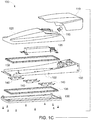
- Figure 1C depicts an exploded view of elongated roadway luminaire 100 in accordance with embodiments. At least one hinge 115 can attach cover 110 to driver housing 120. Driver electronics 125 can be mounted to base unit 150 within the luminaire.
- Frame member 136, 138 can be positioned on opposing sides of base unit 150 to act as gaskets for attachment of optical cover 130 to the roadway luminaire. These gaskets can prevent dirt, water, and other substances from intruding into the interior of the luminaire.
- frame members 136, 138 can be made of rubber, but other sealant materials are also within contemplation of this disclosure.
- optical cover 130 can be transparent, translucent, or a diffuser element.
- base unit 150 is formed from sheet metal material. Opposing edges 152 of the base unit are bent along a longitudinal axis of the base unit to provide structural integrity to the base unit.
- Other components of the luminaire for example, cover door 110, driver housing 120 can be formed from injected molded plastic (e.g., polycarbonate).
- FIG. 2 depicts coupler element 200 of the elongated roadway luminaire in accordance with embodiments.
- Coupler element 200 includes pole bracket 210 and mount bracket 250 that are slideably connected.
- Pole bracket 210 includes a pair of clamp brackets 215, 220.
- the clamp brackets are joined together by fasteners (e.g., bolts), which draw the two clamp brackets together.
- Clamp brackets each include inner-facing surfaces 230, 232. When drawn together these inner-facing arcuate surfaces define an aperture through which a light pole can be extended. Tightening of the fasteners compressably clamps the roadway luminaire to the pole.
- Mount bracket 250 includes a pair of L-shaped brackets 254, 256 having about orthogonal legs. Each leg of the L-shaped bracket includes slotted aperture 260, 262 that are parallel to a longitudinal axis of their respective leg. Pole bracket 210 is fastened to mount bracket 250 by fasteners (e.g., bolts) that pass through the respective aperture 260, 262 into corresponding tabs 240 on each of the clamp brackets 215, 220.
- fasteners e.g., bolts
- the slotted apertures permit roadway luminaire 100 to be pivotably mounted to the pole via clamp brackets 215, 220.
- the slotted aperture provide movement of the roadway luminaire in at least two degrees of freedom (e.g., tilt and rotation) so that the luminaire can move continuously about ⁇ 15° in each of these freedoms with respect to a longitudinal perpendicular axis of the pole.
- the components of pole bracket 210 and mount bracket 250 can be made of stainless steel to provide structural rigidity and reliability to the mount.
- the aperture defined by drawing together clamp brackets 215, 220 is circular. This circular aperture can have a variable diameter of about 42 mm - 76 mm.
- embodiments are not so limited and other diameter ranges are within the scope of this disclosure.
- clamps brackets 215, 220 need not be circular (e.g., other cross sectional shapes can include oval, polygon, etc.). Adjustment of the profile of inner-facing surfaces 230, 232 can be altered from arcuate (depicted) to accommodate these other pole cross sections.
- base unit 150 can include aperture 155 ( FIG. 1B ) that accepts the mounting pole into an interior of the roadway luminaire to reach pole bracket 210.
- the aluminum and stainless steel components are thermally conductive and draw heat away from driver electronics 125 and optical boards 140.
- the coupler brackets can be set discretely for different pole diameters (e.g., about 30, 42, 60, or 76 mm).
- the configuration of the roadway luminaire composed of sheet metal and injection molded parts can have a weight of below about 5 kg. The low-weight of the luminaire decreases the moment-of-force stress on the mounting pole. This low weight also is attractive for weight-critical installations - for example on bridges and other spans.
- the roadway luminaire is easily achieved by using the sheet metal and injection molded components disclosed above. This manufacturing approach reduces lead-time production startup and reduces non-recurring tool costs by eliminating the long-lead time, and expensive, molds needed for the die-cast components of a conventional roadway luminaire.
- the roadway luminaire is lightweight with high structural rigidity, reliability, and thermal mass. Embodying designs allow rapid, customized products to meet customer specifications without incurring large tooling costs associated with die-cast components.
Landscapes
- Engineering & Computer Science (AREA)
- General Engineering & Computer Science (AREA)
- Non-Portable Lighting Devices Or Systems Thereof (AREA)
Abstract
Description
- Municipalities often provide roadway luminaires suspended from a pole along a roadside to illuminate the road. Roadway lighting serves as an important safety feature for busy streets and highways where visibility is essential. Roadway lights provide illumination that can help drivers be aware of their surroundings and provide well-illuminated safety for pedestrians.
- For safety reasons intersections and sharp curves could have a higher concentration of roadway luminaires than, for example, straight sections of a highway. A well-designed lighting plan takes into consideration driver's eye fatigue, headlight illumination, and road features (e.g., inside curve, outside curve, blind spots, pedestrian crossings, etc.). For consistent lighting, the roadway luminaire could be placed at regular intervals.
- Conventional roadway luminaires include die cast components. Such a conventional luminaire can include a die cast coupler that mounts the roadway luminaire to the pole. This die cast coupler limits the range of pole diameters to which the luminaire could be mounted. Additionally, the components of a die cast roadway luminaire can require a long lead-time for production. The weight of a die cast roadway luminaire mounted at the top of a pole creates a large moment-of-force that also drives the physical construction and expense of the lighting pole itself.
-
-
FIG. 1A depicts an isometric top view of an elongated roadway luminaire in accordance with embodiments; -
FIG. 1B depicts an isometric bottom view of the elongated roadway luminaire ofFIG. 1 ; -
FIG. 1C depicts an exploded view of the elongated roadway luminaire ofFIGS. 1A-1B ; and -
FIG. 2 depicts a coupler element of the elongated roadway luminaire in accordance with embodiments. - Embodying systems and methods provide a low production cost outdoor luminaire that includes a base of edge-bent aluminum sheet metal which carries a stainless steel coupler, driver electronics for the light source, and a plastic housing. The aluminum sheet metal has edges bent on its long sides that give rigidity to the construction.
- In accordance with embodiments, the coupler is formed from sheet metal components, and provides versatile coupling to a wide range of pole diameters. The roadway luminaire includes a plastic housing and plastic covers. The housing, covers, and base are assembled together to provide intrusion protection against dust and water that is in compliance with the IP66 ingress protection standard for protection of the luminaire's internal electronics (e.g., driver electronics and optical light source boards). Internal access is provided by one of the covers being hingedly connected to the aluminum sheet metal part for installation and wiring.
-
Figures 1A-1B depicts isometric (respectively top and bottom) views ofelongated roadway luminaire 100 in accordance with embodiments. Elongatedluminaire 100 includescover door 110,driver housing 120,optical cover 130,optical assemblies 140, andbase unit 150. -
Figure 1C depicts an exploded view ofelongated roadway luminaire 100 in accordance with embodiments. At least onehinge 115 can attachcover 110 todriver housing 120.Driver electronics 125 can be mounted tobase unit 150 within the luminaire. -
Frame member base unit 150 to act as gaskets for attachment ofoptical cover 130 to the roadway luminaire. These gaskets can prevent dirt, water, and other substances from intruding into the interior of the luminaire. In someimplementations frame members optical cover 130 can be transparent, translucent, or a diffuser element. - In accordance with embodiments,
base unit 150 is formed from sheet metal material. Opposingedges 152 of the base unit are bent along a longitudinal axis of the base unit to provide structural integrity to the base unit. Other components of the luminaire, for example,cover door 110,driver housing 120 can be formed from injected molded plastic (e.g., polycarbonate). -
Figure 2 depictscoupler element 200 of the elongated roadway luminaire in accordance with embodiments.Coupler element 200 includespole bracket 210 andmount bracket 250 that are slideably connected.Pole bracket 210 includes a pair ofclamp brackets surfaces -
Mount bracket 250 includes a pair of L-shaped brackets slotted aperture Pole bracket 210 is fastened tomount bracket 250 by fasteners (e.g., bolts) that pass through therespective aperture corresponding tabs 240 on each of theclamp brackets - The slotted apertures permit
roadway luminaire 100 to be pivotably mounted to the pole viaclamp brackets - In accordance with embodiments, the components of
pole bracket 210 andmount bracket 250 can be made of stainless steel to provide structural rigidity and reliability to the mount. In accordance with the depicted embodiment ofFIG. 2 , the aperture defined by drawing togetherclamp brackets - The aperture shape defined by drawing together
clamps brackets surfaces - In accordance with embodiments,
base unit 150 can include aperture 155 (FIG. 1B ) that accepts the mounting pole into an interior of the roadway luminaire to reachpole bracket 210. The aluminum and stainless steel components are thermally conductive and draw heat away fromdriver electronics 125 andoptical boards 140. - In accordance with embodiments, the coupler brackets can be set discretely for different pole diameters (e.g., about 30, 42, 60, or 76 mm). In accordance with implementations, the configuration of the roadway luminaire composed of sheet metal and injection molded parts can have a weight of below about 5 kg. The low-weight of the luminaire decreases the moment-of-force stress on the mounting pole. This low weight also is attractive for weight-critical installations - for example on bridges and other spans.
- Manufacture and assembly of the roadway luminaire is easily achieved by using the sheet metal and injection molded components disclosed above. This manufacturing approach reduces lead-time production startup and reduces non-recurring tool costs by eliminating the long-lead time, and expensive, molds needed for the die-cast components of a conventional roadway luminaire. In accordance with embodiments, the roadway luminaire is lightweight with high structural rigidity, reliability, and thermal mass. Embodying designs allow rapid, customized products to meet customer specifications without incurring large tooling costs associated with die-cast components.
- Although described herein are specific hardware and methods, note that any number of other configurations may be provided in accordance with embodiments of the invention. Thus, while there have been shown, described, and pointed out fundamental novel features of the invention, it will be understood that various omissions, substitutions, and changes in the form and details of the illustrated embodiments, and in their operation, may be made by those skilled in the art without departing from the spirit and scope of the invention. Substitutions of elements from one embodiment to another are also fully intended and contemplated. The invention is defined solely with regard to the claims appended hereto, and equivalents of the recitations therein.
Claims (11)
- A roadway luminaire (100) comprising:a base unit (150) having a longitudinal axis including opposing bent edges (152) parallel to the longitudinal axis and an aperture through the base unit configured to accept a mounting pole;a driver housing (120) attached to the base unit;a cover door (110) hingedly attached to the driver housing;the base unit, driver housing, and cover door defining an interior volume of the roadway luminaire;a coupler element (200) attached to a surface of the base unit within the interior volume, the coupler element configured to compressably engage a section of the mounting pole; andthe coupler element configured to provide rotation of the roadway luminaire in at least two degrees of freedom with respect to a longitudinal axis of the mounting pole.
- The roadway luminaire of claim 1, the at least two degrees of freedom including tilt and rotation.
- The roadway luminaire of claim 1 or claim 2, the coupler element including a pole bracket (210) and a mount bracket (250).
- The roadway luminaire of claim 3, the pole bracket including a pair of clamping brackets (220) each including an inner-facing surface, the inner-facing surfaces shaped to form an aperture configured to accommodate a cross section of the mounting pole.
- The roadway luminaire of claim 4, the aperture being circular in shape.
- The roadway luminaire of claim 5, the circular aperture having an adjustable diameter in the range of about 42-76 mm.
- The roadway luminaire of claim 5, the circular aperture having a diameter selected from a group including 30, 42, 60, and 76 mm.
- The roadway luminaire of any of claims 3 to 7, the mount bracket including a pair of L-shaped brackets (254, 256):each L-shaped bracket having two about orthogonal legs;each orthogonal leg having a slotted aperture (260, 262) parallel to a longitudinal axis of the respective orthogonal leg.
- The roadway luminaire of any of claims 3 to 7, the pole bracket slideably attached to the mount bracket.
- The roadway luminaire of any preceding claim, the base unit formed from sheet metal.
- The roadway luminaire of any preceding claim, the driver housing and cover door each formed from an injection molded plastic.
Applications Claiming Priority (1)
| Application Number | Priority Date | Filing Date | Title |
|---|---|---|---|
| US15/273,306 US20180080639A1 (en) | 2016-09-22 | 2016-09-22 | Elongated roadway luminaire structure |
Publications (1)
| Publication Number | Publication Date |
|---|---|
| EP3299696A1 true EP3299696A1 (en) | 2018-03-28 |
Family
ID=59968949
Family Applications (1)
| Application Number | Title | Priority Date | Filing Date |
|---|---|---|---|
| EP17192121.6A Withdrawn EP3299696A1 (en) | 2016-09-22 | 2017-09-20 | Elongated roadway luminaire structure |
Country Status (2)
| Country | Link |
|---|---|
| US (1) | US20180080639A1 (en) |
| EP (1) | EP3299696A1 (en) |
Families Citing this family (7)
| Publication number | Priority date | Publication date | Assignee | Title |
|---|---|---|---|---|
| CN115949892A (en) * | 2016-03-09 | 2023-04-11 | 豪倍照明公司 | Perimeter Lighting |
| USD846172S1 (en) * | 2017-06-01 | 2019-04-16 | Taher & Associates, LLC | Camel solar street light |
| USD859731S1 (en) * | 2017-08-22 | 2019-09-10 | Opple Lighting Co., Ltd. | Light |
| USD861222S1 (en) * | 2017-10-16 | 2019-09-24 | Future Energy Solutions Ip & Trademark, Inc. | Luminaire |
| USD976465S1 (en) * | 2019-08-19 | 2023-01-24 | Chung Han Yu | LED housing |
| USD970779S1 (en) * | 2019-08-19 | 2022-11-22 | Chung Han Yu | LED housing |
| NL2031087B1 (en) * | 2022-02-25 | 2023-09-07 | Schreder Sa | Improved luminaire head for mounting on a pole |
Citations (5)
| Publication number | Priority date | Publication date | Assignee | Title |
|---|---|---|---|---|
| DE102010014371A1 (en) * | 2010-04-09 | 2011-10-13 | Hella Kgaa Hueck & Co. | Luminaire, in particular for attachment to a mast and / or boom, comprising a lamp head and a lamp stand |
| WO2015063807A1 (en) * | 2013-11-04 | 2015-05-07 | ENEL SOLE S.r.l | Lighting apparatus with facilitated disassembly description |
| EP2902700A1 (en) * | 2014-01-31 | 2015-08-05 | D W Windsor Limited | Mounting block |
| US20150260362A1 (en) * | 2014-03-17 | 2015-09-17 | Toshiba Lighting & Technology Corporation | Lighting Device |
| US20160153648A1 (en) * | 2014-12-02 | 2016-06-02 | Posco Led Company, Ltd. | Optical semiconductor lighting apparatus |
Family Cites Families (3)
| Publication number | Priority date | Publication date | Assignee | Title |
|---|---|---|---|---|
| US5803590A (en) * | 1996-03-08 | 1998-09-08 | Thomas & Betts Corporation | Roadway luminaire |
| US9435519B2 (en) * | 2013-01-31 | 2016-09-06 | Cree, Inc. | Light-fixture support assembly |
| US9841154B2 (en) * | 2014-03-15 | 2017-12-12 | Cree, Inc. | Luminaire utilizing light emitting diodes |
-
2016
- 2016-09-22 US US15/273,306 patent/US20180080639A1/en not_active Abandoned
-
2017
- 2017-09-20 EP EP17192121.6A patent/EP3299696A1/en not_active Withdrawn
Patent Citations (5)
| Publication number | Priority date | Publication date | Assignee | Title |
|---|---|---|---|---|
| DE102010014371A1 (en) * | 2010-04-09 | 2011-10-13 | Hella Kgaa Hueck & Co. | Luminaire, in particular for attachment to a mast and / or boom, comprising a lamp head and a lamp stand |
| WO2015063807A1 (en) * | 2013-11-04 | 2015-05-07 | ENEL SOLE S.r.l | Lighting apparatus with facilitated disassembly description |
| EP2902700A1 (en) * | 2014-01-31 | 2015-08-05 | D W Windsor Limited | Mounting block |
| US20150260362A1 (en) * | 2014-03-17 | 2015-09-17 | Toshiba Lighting & Technology Corporation | Lighting Device |
| US20160153648A1 (en) * | 2014-12-02 | 2016-06-02 | Posco Led Company, Ltd. | Optical semiconductor lighting apparatus |
Also Published As
| Publication number | Publication date |
|---|---|
| US20180080639A1 (en) | 2018-03-22 |
Similar Documents
| Publication | Publication Date | Title |
|---|---|---|
| US20180080639A1 (en) | Elongated roadway luminaire structure | |
| US10393331B2 (en) | Lamp and illuminated hardscape | |
| US10605420B2 (en) | Lighting fixture | |
| US7621660B2 (en) | Lighting kit | |
| US10955095B2 (en) | Lighting fixture | |
| CN111051773A (en) | Luminaire for mounting on a pole | |
| CA3214196C (en) | Light fixture with glare reduction panels | |
| KR100992857B1 (en) | Street lamp mechanism for adjusting the irradiation angle of the lamp | |
| ATE481657T1 (en) | SIGN ARRANGEMENT WITH LIGHTING DEVICE AND A REFLECTIVE SIGN | |
| JP2013221279A (en) | Guard fence for road | |
| EP4158108B1 (en) | Road barrier with lighting system | |
| JP2009275349A (en) | Traffic safety sign object | |
| CN211694599U (en) | Street lamp and connecting frame thereof | |
| KR101730810B1 (en) | Angle adjustable deflection reflective crosswalk lights and reflective signage systems using light | |
| KR101604440B1 (en) | Pole type delineator | |
| WO2006091933A2 (en) | Compact road sign display | |
| JP2000064752A (en) | Illuminated portal structure | |
| JP5966794B2 (en) | lighting equipment | |
| KR20200139361A (en) | Double-sided type sign board for cross Road | |
| JP2015010431A (en) | Gaze guide support bracket | |
| KR102196626B1 (en) | device for raising a flag which adjusted high and low | |
| KR101940159B1 (en) | The frame for signboard | |
| KR20090102275A (en) | Traffic sign | |
| CN221276437U (en) | Road guardrail structure | |
| NL2035991B1 (en) | Connector assembly for a luminaire head |
Legal Events
| Date | Code | Title | Description |
|---|---|---|---|
| PUAI | Public reference made under article 153(3) epc to a published international application that has entered the european phase |
Free format text: ORIGINAL CODE: 0009012 |
|
| STAA | Information on the status of an ep patent application or granted ep patent |
Free format text: STATUS: THE APPLICATION HAS BEEN PUBLISHED |
|
| AK | Designated contracting states |
Kind code of ref document: A1 Designated state(s): AL AT BE BG CH CY CZ DE DK EE ES FI FR GB GR HR HU IE IS IT LI LT LU LV MC MK MT NL NO PL PT RO RS SE SI SK SM TR |
|
| AX | Request for extension of the european patent |
Extension state: BA ME |
|
| STAA | Information on the status of an ep patent application or granted ep patent |
Free format text: STATUS: REQUEST FOR EXAMINATION WAS MADE |
|
| 17P | Request for examination filed |
Effective date: 20180928 |
|
| RBV | Designated contracting states (corrected) |
Designated state(s): AL AT BE BG CH CY CZ DE DK EE ES FI FR GB GR HR HU IE IS IT LI LT LU LV MC MK MT NL NO PL PT RO RS SE SI SK SM TR |
|
| RIC1 | Information provided on ipc code assigned before grant |
Ipc: F21V 21/14 20060101ALI20181214BHEP Ipc: F21S 8/08 20060101AFI20181214BHEP Ipc: F21V 21/116 20060101ALI20181214BHEP Ipc: F21V 21/30 20060101ALI20181214BHEP |
|
| GRAP | Despatch of communication of intention to grant a patent |
Free format text: ORIGINAL CODE: EPIDOSNIGR1 |
|
| STAA | Information on the status of an ep patent application or granted ep patent |
Free format text: STATUS: GRANT OF PATENT IS INTENDED |
|
| INTG | Intention to grant announced |
Effective date: 20190214 |
|
| STAA | Information on the status of an ep patent application or granted ep patent |
Free format text: STATUS: THE APPLICATION IS DEEMED TO BE WITHDRAWN |
|
| 18D | Application deemed to be withdrawn |
Effective date: 20190625 |