EP3299671A1 - Convective cooling of a pressurized gearbox - Google Patents
Convective cooling of a pressurized gearbox Download PDFInfo
- Publication number
- EP3299671A1 EP3299671A1 EP17190421.2A EP17190421A EP3299671A1 EP 3299671 A1 EP3299671 A1 EP 3299671A1 EP 17190421 A EP17190421 A EP 17190421A EP 3299671 A1 EP3299671 A1 EP 3299671A1
- Authority
- EP
- European Patent Office
- Prior art keywords
- gearbox
- pressurized
- lubricant
- housing
- cooling
- Prior art date
- Legal status (The legal status is an assumption and is not a legal conclusion. Google has not performed a legal analysis and makes no representation as to the accuracy of the status listed.)
- Granted
Links
Images


Classifications
-
- F—MECHANICAL ENGINEERING; LIGHTING; HEATING; WEAPONS; BLASTING
- F16—ENGINEERING ELEMENTS AND UNITS; GENERAL MEASURES FOR PRODUCING AND MAINTAINING EFFECTIVE FUNCTIONING OF MACHINES OR INSTALLATIONS; THERMAL INSULATION IN GENERAL
- F16H—GEARING
- F16H57/00—General details of gearing
- F16H57/04—Features relating to lubrication or cooling or heating
- F16H57/0412—Cooling or heating; Control of temperature
- F16H57/0415—Air cooling or ventilation; Heat exchangers; Thermal insulations
- F16H57/0417—Heat exchangers adapted or integrated in the gearing
-
- F—MECHANICAL ENGINEERING; LIGHTING; HEATING; WEAPONS; BLASTING
- F16—ENGINEERING ELEMENTS AND UNITS; GENERAL MEASURES FOR PRODUCING AND MAINTAINING EFFECTIVE FUNCTIONING OF MACHINES OR INSTALLATIONS; THERMAL INSULATION IN GENERAL
- F16H—GEARING
- F16H57/00—General details of gearing
- F16H57/04—Features relating to lubrication or cooling or heating
- F16H57/0412—Cooling or heating; Control of temperature
- F16H57/0415—Air cooling or ventilation; Heat exchangers; Thermal insulations
- F16H57/0416—Air cooling or ventilation
-
- B—PERFORMING OPERATIONS; TRANSPORTING
- B64—AIRCRAFT; AVIATION; COSMONAUTICS
- B64C—AEROPLANES; HELICOPTERS
- B64C27/00—Rotorcraft; Rotors peculiar thereto
- B64C27/04—Helicopters
- B64C27/12—Rotor drives
-
- B—PERFORMING OPERATIONS; TRANSPORTING
- B64—AIRCRAFT; AVIATION; COSMONAUTICS
- B64C—AEROPLANES; HELICOPTERS
- B64C27/00—Rotorcraft; Rotors peculiar thereto
- B64C27/04—Helicopters
- B64C27/12—Rotor drives
- B64C27/14—Direct drive between power plant and rotor hub
-
- F—MECHANICAL ENGINEERING; LIGHTING; HEATING; WEAPONS; BLASTING
- F16—ENGINEERING ELEMENTS AND UNITS; GENERAL MEASURES FOR PRODUCING AND MAINTAINING EFFECTIVE FUNCTIONING OF MACHINES OR INSTALLATIONS; THERMAL INSULATION IN GENERAL
- F16H—GEARING
- F16H57/00—General details of gearing
- F16H57/02—Gearboxes; Mounting gearing therein
-
- F—MECHANICAL ENGINEERING; LIGHTING; HEATING; WEAPONS; BLASTING
- F16—ENGINEERING ELEMENTS AND UNITS; GENERAL MEASURES FOR PRODUCING AND MAINTAINING EFFECTIVE FUNCTIONING OF MACHINES OR INSTALLATIONS; THERMAL INSULATION IN GENERAL
- F16H—GEARING
- F16H57/00—General details of gearing
- F16H57/04—Features relating to lubrication or cooling or heating
- F16H57/0434—Features relating to lubrication or cooling or heating relating to lubrication supply, e.g. pumps; Pressure control
- F16H57/0436—Pumps
-
- F—MECHANICAL ENGINEERING; LIGHTING; HEATING; WEAPONS; BLASTING
- F16—ENGINEERING ELEMENTS AND UNITS; GENERAL MEASURES FOR PRODUCING AND MAINTAINING EFFECTIVE FUNCTIONING OF MACHINES OR INSTALLATIONS; THERMAL INSULATION IN GENERAL
- F16H—GEARING
- F16H57/00—General details of gearing
- F16H57/04—Features relating to lubrication or cooling or heating
- F16H57/045—Lubricant storage reservoirs, e.g. reservoirs in addition to a gear sump for collecting lubricant in the upper part of a gear case
-
- B—PERFORMING OPERATIONS; TRANSPORTING
- B64—AIRCRAFT; AVIATION; COSMONAUTICS
- B64C—AEROPLANES; HELICOPTERS
- B64C27/00—Rotorcraft; Rotors peculiar thereto
- B64C27/82—Rotorcraft; Rotors peculiar thereto characterised by the provision of an auxiliary rotor or fluid-jet device for counter-balancing lifting rotor torque or changing direction of rotorcraft
-
- F—MECHANICAL ENGINEERING; LIGHTING; HEATING; WEAPONS; BLASTING
- F16—ENGINEERING ELEMENTS AND UNITS; GENERAL MEASURES FOR PRODUCING AND MAINTAINING EFFECTIVE FUNCTIONING OF MACHINES OR INSTALLATIONS; THERMAL INSULATION IN GENERAL
- F16H—GEARING
- F16H57/00—General details of gearing
- F16H57/02—Gearboxes; Mounting gearing therein
- F16H2057/02039—Gearboxes for particular applications
-
- F—MECHANICAL ENGINEERING; LIGHTING; HEATING; WEAPONS; BLASTING
- F16—ENGINEERING ELEMENTS AND UNITS; GENERAL MEASURES FOR PRODUCING AND MAINTAINING EFFECTIVE FUNCTIONING OF MACHINES OR INSTALLATIONS; THERMAL INSULATION IN GENERAL
- F16H—GEARING
- F16H57/00—General details of gearing
- F16H57/04—Features relating to lubrication or cooling or heating
- F16H57/0402—Cleaning of lubricants, e.g. filters or magnets
- F16H57/0404—Lubricant filters
-
- F—MECHANICAL ENGINEERING; LIGHTING; HEATING; WEAPONS; BLASTING
- F16—ENGINEERING ELEMENTS AND UNITS; GENERAL MEASURES FOR PRODUCING AND MAINTAINING EFFECTIVE FUNCTIONING OF MACHINES OR INSTALLATIONS; THERMAL INSULATION IN GENERAL
- F16H—GEARING
- F16H57/00—General details of gearing
- F16H57/04—Features relating to lubrication or cooling or heating
- F16H57/0434—Features relating to lubrication or cooling or heating relating to lubrication supply, e.g. pumps; Pressure control
- F16H57/0435—Pressure control for supplying lubricant; Circuits or valves therefor
Definitions
- the present invention relates in general to the field of device cooling, and more particularly, to an apparatus and method for convective cooling of a pressurized gearbox.
- a lubrication system that includes a reserve housing configured to retain a lubrication fluid.
- a supply line in fluid communication with the reserve housing is configured to provide pressurized lubrication fluid to the reserve housing.
- An overflow tube has an overflow port, the overflow tube being configured to prevent the volume of the lubrication fluid from exceeding a certain amount.
- a metering jet is configured to allow the lubrication fluid to flow from the reserve housing onto a component, such as a bearing, in the gearbox at a predetermined rate. The metering jet provides flow of the lubrication fluid onto the bearing even when the supply line no longer provides pressurized lubrication fluid to the reserve housing.
- the present invention includes a cooling system for a gearbox, the cooling system comprising: a pressurized housing in fluid communication with the gearbox configured to circulate a pressurized lubricant; and one or more cooling fins about the pressurized housing, wherein heat from the pressurized lubricant within the pressurized housing is actively convected through the one or more cooling fins.
- the cooling fins are metal, composite, ceramic, polymer, or combinations thereof.
- the cooling fins are disposed over a majority of an exterior surface of the pressurized housing to passively cool the pressurized lubricant.
- the gearbox is connected to an engine in a car, truck, locomotive, aircraft, or rotorcraft.
- the gearbox is a main rotor gearbox, an intermediate gearbox, or a tail rotor gearbox of a rotorcraft.
- the pressurized lubricant is a petroleum lubricant, a mineral oil, a plant oil, a synthetic lubricant, a high temperature lubricant, or combinations thereof.
- the gearbox further comprises at least one of: a filter, a pump, a bearing, or one or more valves for the pressurized lubricant.
- a length and a width of the cooling fins are modified to optimize the amount of heat convected by the cooling fins.
- the cooling system further comprises an active cooling system for the pressurized lubricant.
- the gearbox is at least partially lubricated by the pressurized lubricant.
- the present invention includes a gearbox for an aircraft, the gearbox comprising: a housing that encloses a plurality of gearbox components, wherein the gearbox components are at least partially lubricated by a pressurized lubricant; a pump that pressurizes and circulates the pressurized lubricant; a pressurized passage in fluid communication with the housing configured to circulate the pressurized lubricant about the gearbox components; and one or more cooling fins about the pressurized passage, wherein heat from the pressurized lubricant circulated within the pressurized passage is actively convected through the one or more cooling fins.
- the cooling fins are metal, composite, ceramic, polymer, or combinations thereof.
- the cooling fins are disposed over a majority of an exterior surface of the pressurized passage to passively cool the pressurized lubricant.
- the gearbox is connected to an engine in a car, truck, locomotive, aircraft, or rotorcraft.
- the gearbox is a main rotor gearbox, an intermediate gearbox, or a tail rotor gearbox of a rotorcraft.
- the pressurized lubricant is a petroleum lubricant, a mineral oil, a plant oil, a synthetic lubricant, a high temperature lubricant, or combinations thereof.
- the gearbox further comprises at least one of: a filter, a pump, a bearing, or one or more valves for the pressurized lubricant.
- a length and a width of the cooling fins are modified to optimize the amount of heat convected by the cooling fins.
- the gearbox further comprises an active cooling system for the pressurized lubricant.
- the present invention includes a method for cooling a gearbox that is at least partially lubricated by a pressurized lubricant, the method comprising: providing a pressurized housing in fluid communication with the gearbox configured to circulate the pressurized lubricant; and positioning one or more cooling fins about the pressurized housing, wherein heat from the pressurized lubricant within the pressurized housing is actively convected through the one or more cooling fins.
- kits for a cooling system for a gearbox comprising: a pressurized housing comprising one or more cooling fins about the pressurized housing, wherein the pressurized housing is configured to attach to the gearbox, wherein the gearbox is at least partially lubricated by a pressurized lubricant, wherein heat from the pressurized lubricant within the pressurized housing is actively convected through the one or more cooling fins; and instructions for removing a pressurized housing without fins and replacing it with the pressurized housing having cooling fins.
- This invention is generally in the field of drive systems, and relates specifically to pressurized gearboxes that are cooled through convection to the surrounding environment.
- gearboxes utilized fins located on the sump area of the gearbox housing where the stagnant oil sits during its dwell time or along unpressurized walls of the housing to reject the bulk heat of the gearbox.
- Rotorcraft 101 has a rotor system 103 with a plurality of main rotor blades 111.
- Rotorcraft 101 further includes a fuselage 105, landing gear 107, a tail member 109, and tail rotor blades 113.
- An engine 115 supplies torque to a main rotor mast 117 via a gearbox 327 for the rotating of main rotor blades 111.
- Engine 115 also supplies torque to a tail rotor drive shaft 119 for the rotating of tail rotor blades 113.
- the pitch of each main rotor blade 111 can be selectively controlled in order to selectively control direction, thrust, and lift of rotorcraft 101.
- the pitch of tail rotor blades 113 can be selectively controlled in order to selectively control yaw of rotorcraft 101.
- Rotorcraft 101 is illustrated for exemplary purposes only. It should be appreciated that the system of the present application may be used on aircraft other than rotorcraft, such as airplanes, tilt rotors, unmanned aircraft, to name a few examples. Further, the system of the present application may be used on non-aircraft vehicles and implementations, for example, cars, trucks, locomotives, boats, spacecraft, or combinations thereof.
- This invention places addition surface area in the form of fins directly over a pressurized oil circuit within, attached to, and/or in fluid communication with the gearbox to take advantage of the addition heat rejection due to the pressurized oil flow carrying heated oil directly under the fins to aid in the convection of heat from the gearbox to the surrounding environment.
- Pressurized oil within the gearbox is circulated through pressurized passages, cores, or annuli within the gearbox system to lubricate and cool the dynamic components.
- Increasing the surface area of the gearbox housing with the addition of fins has been the common practice for cooling the gearbox through convection to the surrounding environment. These fins are usually located on the sump area of the gearbox housing where the stagnant oil sits during its dwell time.
- This invention adds cooling fins directly over pressurized circuits on the gearbox housings to take advantage of the oil movement to carry heat to the housing and fins.
- FIG. 3A is an isometric view of a housing 200 of the prior art that can be attached to a gearbox (not depicted) in the form of an annulus that is adapted to contain a pressurized lubricant.
- Housing 200 includes exterior surface 202, an opening 204, and one or more grooves 206a, b, c that are used to insert O-rings that are used to maintain the pressurized fluid within the annulus.
- FIG. 3B is an isometric view of a housing 300 of the present invention.
- the housing 300 has an exterior surface 302, an opening or annulus 304, grooves 306a, b, c, but further includes, fins 308 that are attached to, or formed integral with, the housing 300 on the exterior surface 302.
- the fins 308 depicted can have varying lengths, thicknesses, and spacings, as shown at 310, which can be adapted to increase or decrease the convection of the pressurized lubricant or oil.
- the fins 308 in this embodiment are depicted as being generally parallel to the longitudinal axis (A-A') of the housing 300, the fins 308 can be in any orientation, such as rings around the external surface 302 and generally perpendicular to the longitudinal axis (A-A') of the housing 300, diagonal with respect to the longitudinal axis (A-A') of the housing 300, or any combinations thereof.
- the length and width of the fins 308 can also be adapted to provide for fasteners of the housing to the gearbox or to other components, such as filters, gears, valves, fluid lines, etc. (not depicted).
- the cooling fins may be made from one or more suitable materials, including metals, composites, ceramics, and/or polymers.
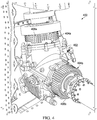
- FIG. 4 is an isometric view of one exemplary and non-limiting example of a pressurized gearbox 400 for a tail rotor of a rotorcraft. While a pressurized intermediate gearbox 400 is depicted, the present invention can be used with any pressurized gearbox.
- the pressurized gear mechanism 402, in this case is shown with a first and a second pressurized annuli 404a, b, shown with fins 406a, b, respectively.
- the first and a second pressurized annuli 404a, b radiate heat from a pressurized lubricating fluid or oil within the first and second pressurized annuli 404a, b, to passively reduce the temperature of the pressurized lubricating fluid or oil in contact with the gearbox housing.
- the present invention can be used with any pressurized gearbox.
- Non-limiting examples of where a pressurized gearbox can be used includes the main engine to transmission gearbox, any gears used as couplers, the main rotor gearbox, the intermediate gearbox, or the tail rotor gearbox.
- the words “comprising” (and any form of comprising, such as “comprise” and “comprises"), “having” (and any form of having, such as “have” and “has”), “including” (and any form of including, such as “includes” and “include”) or “containing” (and any form of containing, such as “contains” and “contain”) are inclusive or open-ended and do not exclude additional, unrecited elements or method steps.
- “comprising” may be replaced with “consisting essentially of” or “consisting of'.
- the phrase “consisting essentially of” requires the specified integer(s) or steps as well as those that do not materially affect the character or function of the claimed invention.
- the term “consisting” is used to indicate the presence of the recited integer (e.g., a feature, an element, a characteristic, a property, a method/process step or a limitation) or group of integers (e.g., feature(s), element(s), characteristic(s), propertie(s), method/process steps or limitation(s)) only.
- words of approximation such as, without limitation, "about”, “substantial” or “substantially” refers to a condition that when so modified is understood to not necessarily be absolute or perfect but would be considered close enough to those of ordinary skill in the art to warrant designating the condition as being present.
- the extent to which the description may vary will depend on how great a change can be instituted and still have one of ordinary skilled in the art recognize the modified feature as still having the required characteristics and capabilities of the unmodified feature.
- a numerical value herein that is modified by a word of approximation such as "about” may vary from the stated value by at least ⁇ 1,2, 3, 4, 5, 6, 7, 10, 12 or 15%.
Landscapes
- Engineering & Computer Science (AREA)
- General Engineering & Computer Science (AREA)
- Mechanical Engineering (AREA)
- Aviation & Aerospace Engineering (AREA)
- Lubricants (AREA)
- General Details Of Gearings (AREA)
Abstract
Description
- This application claims the benefit of provisional
U.S. Patent Application Ser. No. 62/399,097 U.S. Patent Application Ser. No. 62/423,371 - This application is not the subject of any federally sponsored research or development.
- The present invention relates in general to the field of device cooling, and more particularly, to an apparatus and method for convective cooling of a pressurized gearbox.
- Without limiting the scope of the invention, its background is described in connection with lubrication systems.
- One such invention is taught in
U.S. Patent No. 9,458,923, issued to Poster, et al. - In one embodiment, the present invention includes a cooling system for a gearbox, the cooling system comprising: a pressurized housing in fluid communication with the gearbox configured to circulate a pressurized lubricant; and one or more cooling fins about the pressurized housing, wherein heat from the pressurized lubricant within the pressurized housing is actively convected through the one or more cooling fins. In one aspect, the cooling fins are metal, composite, ceramic, polymer, or combinations thereof. In another aspect, the cooling fins are disposed over a majority of an exterior surface of the pressurized housing to passively cool the pressurized lubricant. In another aspect, the gearbox is connected to an engine in a car, truck, locomotive, aircraft, or rotorcraft. In another aspect, the gearbox is a main rotor gearbox, an intermediate gearbox, or a tail rotor gearbox of a rotorcraft. In another aspect, the pressurized lubricant is a petroleum lubricant, a mineral oil, a plant oil, a synthetic lubricant, a high temperature lubricant, or combinations thereof. In another aspect, the gearbox further comprises at least one of: a filter, a pump, a bearing, or one or more valves for the pressurized lubricant. In another aspect, a length and a width of the cooling fins are modified to optimize the amount of heat convected by the cooling fins. In another aspect, the cooling system further comprises an active cooling system for the pressurized lubricant. In another aspect, the gearbox is at least partially lubricated by the pressurized lubricant.
- In another embodiment, the present invention includes a gearbox for an aircraft, the gearbox comprising: a housing that encloses a plurality of gearbox components, wherein the gearbox components are at least partially lubricated by a pressurized lubricant; a pump that pressurizes and circulates the pressurized lubricant; a pressurized passage in fluid communication with the housing configured to circulate the pressurized lubricant about the gearbox components; and one or more cooling fins about the pressurized passage, wherein heat from the pressurized lubricant circulated within the pressurized passage is actively convected through the one or more cooling fins. In one aspect, the cooling fins are metal, composite, ceramic, polymer, or combinations thereof. In another aspect, the cooling fins are disposed over a majority of an exterior surface of the pressurized passage to passively cool the pressurized lubricant. In another aspect, the gearbox is connected to an engine in a car, truck, locomotive, aircraft, or rotorcraft. In another aspect, the gearbox is a main rotor gearbox, an intermediate gearbox, or a tail rotor gearbox of a rotorcraft. In another aspect, the pressurized lubricant is a petroleum lubricant, a mineral oil, a plant oil, a synthetic lubricant, a high temperature lubricant, or combinations thereof. In another aspect, the gearbox further comprises at least one of: a filter, a pump, a bearing, or one or more valves for the pressurized lubricant. In another aspect, a length and a width of the cooling fins are modified to optimize the amount of heat convected by the cooling fins. In another aspect, the gearbox further comprises an active cooling system for the pressurized lubricant.
- In another embodiment, the present invention includes a method for cooling a gearbox that is at least partially lubricated by a pressurized lubricant, the method comprising: providing a pressurized housing in fluid communication with the gearbox configured to circulate the pressurized lubricant; and positioning one or more cooling fins about the pressurized housing, wherein heat from the pressurized lubricant within the pressurized housing is actively convected through the one or more cooling fins.
- Yet another embodiment of the present invention includes a kit for a cooling system for a gearbox, the kit comprising: a pressurized housing comprising one or more cooling fins about the pressurized housing, wherein the pressurized housing is configured to attach to the gearbox, wherein the gearbox is at least partially lubricated by a pressurized lubricant, wherein heat from the pressurized lubricant within the pressurized housing is actively convected through the one or more cooling fins; and instructions for removing a pressurized housing without fins and replacing it with the pressurized housing having cooling fins.
- For a more complete understanding of the features and advantages of the present invention, reference is now made to the detailed description of the invention along with the accompanying figures and in which:
-
FIG. 1 is a schematic side view of a rotorcraft, according to an illustrative embodiment of the present application; -
FIG. 2 is a partial schematic side view of the rotorcraft ofFIG. 1 , according to an illustrative embodiment of the present application; -
FIG. 3A is an isometric view of an oil annulus for pressurized lubricant flow of the prior art; -
FIG. 3B is an isometric view of the present invention, in which a lubricant annulus for pressurized lubricant flow of the present invention further comprises a number of fins that directly convect the heat from the pressurized lubricant within the annulus; -
FIG. 4 is an isometric view of the present invention connected to a gear box at two separate locations to radiate heat from the pressurized lubricating fluid within the annulus; - Illustrative embodiments of the system of the present application are described below. In the interest of clarity, not all features of an actual implementation are described in this specification. It will of course be appreciated that in the development of any such actual embodiment, numerous implementation-specific decisions must be made to achieve the developer's specific goals, such as compliance with system-related and business-related constraints, which will vary from one implementation to another. Moreover, it will be appreciated that such a development effort might be complex and time-consuming but would nevertheless be a routine undertaking for those of ordinary skill in the art having the benefit of this disclosure.
- In the specification, reference may be made to the spatial relationships between various components and to the spatial orientation of various aspects of components as the devices are depicted in the attached drawings. However, as will be recognized by those skilled in the art after a complete reading of the present application, the devices, members, apparatuses, etc. described herein may be positioned in any desired orientation. Thus, the use of terms such as "above," "below," "upper," "lower," or other like terms to describe a spatial relationship between various components or to describe the spatial orientation of aspects of such components should be understood to describe a relative relationship between the components or a spatial orientation of aspects of such components, respectively, as the device described herein may be oriented in any desired direction.
- This invention is generally in the field of drive systems, and relates specifically to pressurized gearboxes that are cooled through convection to the surrounding environment. In the past, gearboxes utilized fins located on the sump area of the gearbox housing where the stagnant oil sits during its dwell time or along unpressurized walls of the housing to reject the bulk heat of the gearbox.
- Referring to
FIGS. 1 and 2 in the drawings, arotorcraft 101 is illustrated. Rotorcraft 101 has arotor system 103 with a plurality ofmain rotor blades 111. Rotorcraft 101 further includes afuselage 105,landing gear 107, atail member 109, andtail rotor blades 113. Anengine 115 supplies torque to amain rotor mast 117 via agearbox 327 for the rotating ofmain rotor blades 111.Engine 115 also supplies torque to a tailrotor drive shaft 119 for the rotating oftail rotor blades 113. The pitch of eachmain rotor blade 111 can be selectively controlled in order to selectively control direction, thrust, and lift ofrotorcraft 101. Further, the pitch oftail rotor blades 113 can be selectively controlled in order to selectively control yaw ofrotorcraft 101. Rotorcraft 101 is illustrated for exemplary purposes only. It should be appreciated that the system of the present application may be used on aircraft other than rotorcraft, such as airplanes, tilt rotors, unmanned aircraft, to name a few examples. Further, the system of the present application may be used on non-aircraft vehicles and implementations, for example, cars, trucks, locomotives, boats, spacecraft, or combinations thereof. - This invention places addition surface area in the form of fins directly over a pressurized oil circuit within, attached to, and/or in fluid communication with the gearbox to take advantage of the addition heat rejection due to the pressurized oil flow carrying heated oil directly under the fins to aid in the convection of heat from the gearbox to the surrounding environment.
- Pressurized oil within the gearbox is circulated through pressurized passages, cores, or annuli within the gearbox system to lubricate and cool the dynamic components. Increasing the surface area of the gearbox housing with the addition of fins has been the common practice for cooling the gearbox through convection to the surrounding environment. These fins are usually located on the sump area of the gearbox housing where the stagnant oil sits during its dwell time. This invention adds cooling fins directly over pressurized circuits on the gearbox housings to take advantage of the oil movement to carry heat to the housing and fins.
-
FIG. 3A is an isometric view of ahousing 200 of the prior art that can be attached to a gearbox (not depicted) in the form of an annulus that is adapted to contain a pressurized lubricant.Housing 200 includesexterior surface 202, anopening 204, and one ormore grooves 206a, b, c that are used to insert O-rings that are used to maintain the pressurized fluid within the annulus. -
FIG. 3B is an isometric view of ahousing 300 of the present invention. In this embodiment, thehousing 300 has anexterior surface 302, an opening orannulus 304,grooves 306a, b, c, but further includes,fins 308 that are attached to, or formed integral with, thehousing 300 on theexterior surface 302. Thefins 308 depicted can have varying lengths, thicknesses, and spacings, as shown at 310, which can be adapted to increase or decrease the convection of the pressurized lubricant or oil. Further, while thefins 308 in this embodiment are depicted as being generally parallel to the longitudinal axis (A-A') of thehousing 300, thefins 308 can be in any orientation, such as rings around theexternal surface 302 and generally perpendicular to the longitudinal axis (A-A') of thehousing 300, diagonal with respect to the longitudinal axis (A-A') of thehousing 300, or any combinations thereof. The length and width of thefins 308 can also be adapted to provide for fasteners of the housing to the gearbox or to other components, such as filters, gears, valves, fluid lines, etc. (not depicted). The cooling fins may be made from one or more suitable materials, including metals, composites, ceramics, and/or polymers. -
FIG. 4 is an isometric view of one exemplary and non-limiting example of apressurized gearbox 400 for a tail rotor of a rotorcraft. While a pressurizedintermediate gearbox 400 is depicted, the present invention can be used with any pressurized gearbox. Thepressurized gear mechanism 402, in this case is shown with a first and a second pressurized annuli 404a, b, shown withfins 406a, b, respectively. The first and a second pressurized annuli 404a, b, radiate heat from a pressurized lubricating fluid or oil within the first and second pressurized annuli 404a, b, to passively reduce the temperature of the pressurized lubricating fluid or oil in contact with the gearbox housing. The present invention can be used with any pressurized gearbox. Non-limiting examples of where a pressurized gearbox can be used includes the main engine to transmission gearbox, any gears used as couplers, the main rotor gearbox, the intermediate gearbox, or the tail rotor gearbox. - It will be understood that particular embodiments described herein are shown by way of illustration and not as limitations of the invention. The principal features of this invention can be employed in various embodiments without departing from the scope of the invention. Those skilled in the art will recognize, or be able to ascertain using no more than routine experimentation, numerous equivalents to the specific procedures described herein. Such equivalents are considered to be within the scope of this invention and are covered by the claims.
- All publications and patent applications mentioned in the specification are indicative of the level of skill of those skilled in the art to which this invention pertains. All publications and patent applications are herein incorporated by reference to the same extent as if each individual publication or patent application was specifically and individually indicated to be incorporated by reference.
- The use of the word "a" or "an" when used in conjunction with the term "comprising" in the claims and/or the specification may mean "one," but it is also consistent with the meaning of "one or more," "at least one," and "one or more than one." The use of the term "or" in the claims is used to mean "and/or" unless explicitly indicated to refer to alternatives only or the alternatives are mutually exclusive, although the disclosure supports a definition that refers to only alternatives and "and/or." Throughout this application, the term "about" is used to indicate that a value includes the inherent variation of error for the device, the method being employed to determine the value, or the variation that exists among the study subjects.
- As used in this specification and claim(s), the words "comprising" (and any form of comprising, such as "comprise" and "comprises"), "having" (and any form of having, such as "have" and "has"), "including" (and any form of including, such as "includes" and "include") or "containing" (and any form of containing, such as "contains" and "contain") are inclusive or open-ended and do not exclude additional, unrecited elements or method steps. In embodiments of any of the compositions and methods provided herein, "comprising" may be replaced with "consisting essentially of" or "consisting of'. As used herein, the phrase "consisting essentially of" requires the specified integer(s) or steps as well as those that do not materially affect the character or function of the claimed invention. As used herein, the term "consisting" is used to indicate the presence of the recited integer (e.g., a feature, an element, a characteristic, a property, a method/process step or a limitation) or group of integers (e.g., feature(s), element(s), characteristic(s), propertie(s), method/process steps or limitation(s)) only.
- The term "or combinations thereof" as used herein refers to all permutations and combinations of the listed items preceding the term. For example, "A, B, C, or combinations thereof" is intended to include at least one of: A, B, C, AB, AC, BC, or ABC, and if order is important in a particular context, also BA, CA, CB, CBA, BCA, ACB, BAC, or CAB. Continuing with this example, expressly included are combinations that contain repeats of one or more item or term, such as BB, AAA, AB, BBC, AAABCCCC, CBBAAA, CABABB, and so forth. The skilled artisan will understand that typically there is no limit on the number of items or terms in any combination, unless otherwise apparent from the context.
- As used herein, words of approximation such as, without limitation, "about", "substantial" or "substantially" refers to a condition that when so modified is understood to not necessarily be absolute or perfect but would be considered close enough to those of ordinary skill in the art to warrant designating the condition as being present. The extent to which the description may vary will depend on how great a change can be instituted and still have one of ordinary skilled in the art recognize the modified feature as still having the required characteristics and capabilities of the unmodified feature. In general, but subject to the preceding discussion, a numerical value herein that is modified by a word of approximation such as "about" may vary from the stated value by at least ±1,2, 3, 4, 5, 6, 7, 10, 12 or 15%.
- All of the devices and/or methods disclosed and claimed herein can be made and executed without undue experimentation in light of the present disclosure. While the devices and/or and methods of this invention have been described in terms of preferred embodiments, it will be apparent to those of skill in the art that variations may be applied to the compositions and/or methods and in the steps or in the sequence of steps of the method described herein without departing from the concept, spirit and scope of the invention. All such similar substitutes and modifications apparent to those skilled in the art are deemed to be within the spirit, scope and concept of the invention as defined by the appended claims.
- Furthermore, no limitations are intended to the details of construction or design herein shown, other than as described in the claims below. It is therefore evident that the particular embodiments disclosed above may be altered or modified and all such variations are considered within the scope and spirit of the disclosure. Accordingly, the protection sought herein is as set forth in the claims below.
- To aid the Patent Office, and any readers of any patent issued on this application in interpreting the claims appended hereto, applicants wish to note that they do not intend any of the appended claims to invoke paragraph 6 of 35 U.S.C. § 112 as it exists on the date of filing hereof unless the words "means for" or "step for" are explicitly used in the particular claim.
Claims (13)
- A cooling system for a gearbox, the cooling system comprising:a pressurized housing in fluid communication with the gearbox configured to circulate a pressurized lubricant; andone or more cooling fins about the pressurized housing, wherein heat from the pressurized lubricant within the pressurized housing is actively convected through the one or more cooling fins.
- A gearbox for an aircraft, the gearbox comprising:a housing that encloses a plurality of gearbox components, wherein the gearbox components are at least partially lubricated by a pressurized lubricant;a pump that pressurizes and circulates the pressurized lubricant;a pressurized passage in fluid communication with the housing configured to circulate the pressurized lubricant about the gearbox components; andone or more cooling fins about the pressurized passage, wherein heat from the pressurized lubricant circulated within the pressurized passage is actively convected through the one or more cooling fins.
- The cooling system of claim 1, or the gearbox of claim 2, wherein the cooling fins are metal, composite, ceramic, polymer, or combinations thereof.
- The cooling system of claim 1 or claim 3, or the gearbox of claim 2 or claim 3, wherein the cooling fins are disposed over a majority of an exterior surface of the pressurized housing to passively cool the pressurized lubricant.
- The cooling system of any preceding system claim, or the gearbox of any preceding gearbox claim, wherein the gearbox is connected to an engine in a car, truck, locomotive, aircraft, or rotorcraft.
- The cooling system of any preceding system claim, or the gearbox of any preceding gearbox claim, wherein the gearbox is a main rotor gearbox, an intermediate gearbox, or a tail rotor gearbox of a rotorcraft.
- The cooling system of any preceding system claim, or the gearbox of any preceding gearbox claim, wherein the pressurized lubricant is a petroleum lubricant, a mineral oil, a plant oil, a synthetic lubricant, a high temperature lubricant, or combinations thereof.
- The cooling system of any preceding system claim, or the gearbox of any preceding gearbox claim, wherein the gearbox further comprises at least one of: a filter, a pump, a bearing, or one or more valves for the pressurized lubricant.
- The cooling system of any preceding system claim, or the gearbox of any preceding gearbox claim, wherein a length and a width of the cooling fins are modified to optimize the amount of heat convected by the cooling fins.
- The cooling system of any preceding system claim, or the gearbox of any preceding gearbox claim, further comprising an active cooling system for the pressurized lubricant.
- The cooling system of any preceding system claim, wherein the gearbox is at least partially lubricated by the pressurized lubricant.
- A method for cooling a gearbox that is at least partially lubricated by a pressurized lubricant, the method comprising:providing a pressurized housing in fluid communication with the gearbox configured to circulate the pressurized lubricant; andpositioning one or more cooling fins about the pressurized housing, wherein heat from the pressurized lubricant within the pressurized housing is actively convected through the one or more cooling fins.
- A kit for a cooling system for a gearbox, the kit comprising:a pressurized housing comprising one or more cooling fins about the pressurized housing, wherein the pressurized housing is configured to attach to the gearbox, wherein the gearbox is at least partially lubricated by a pressurized lubricant, wherein heat from the pressurized lubricant within the pressurized housing is actively convected through the one or more cooling fins; andinstructions for removing a pressurized housing without fins and replacing it with the pressurized housing having cooling fins.
Applications Claiming Priority (3)
| Application Number | Priority Date | Filing Date | Title |
|---|---|---|---|
| US201662399097P | 2016-09-23 | 2016-09-23 | |
| US201662423371P | 2016-11-17 | 2016-11-17 | |
| US15/354,715 US11162572B2 (en) | 2016-09-23 | 2016-11-17 | Convective cooling of a pressurized gearbox |
Publications (2)
| Publication Number | Publication Date |
|---|---|
| EP3299671A1 true EP3299671A1 (en) | 2018-03-28 |
| EP3299671B1 EP3299671B1 (en) | 2022-02-23 |
Family
ID=59846505
Family Applications (1)
| Application Number | Title | Priority Date | Filing Date |
|---|---|---|---|
| EP17190421.2A Active EP3299671B1 (en) | 2016-09-23 | 2017-09-11 | Convective cooling of a pressurized gearbox |
Country Status (2)
| Country | Link |
|---|---|
| US (1) | US11162572B2 (en) |
| EP (1) | EP3299671B1 (en) |
Cited By (1)
| Publication number | Priority date | Publication date | Assignee | Title |
|---|---|---|---|---|
| US11162572B2 (en) | 2016-09-23 | 2021-11-02 | Textron Innovations Inc. | Convective cooling of a pressurized gearbox |
Families Citing this family (2)
| Publication number | Priority date | Publication date | Assignee | Title |
|---|---|---|---|---|
| JP7373987B2 (en) * | 2019-12-26 | 2023-11-06 | 住友重機械工業株式会社 | Orthogonal reduction gear |
| EP3929078B1 (en) * | 2020-06-25 | 2022-08-03 | LEONARDO S.p.A. | Helicopter |
Citations (6)
| Publication number | Priority date | Publication date | Assignee | Title |
|---|---|---|---|---|
| EP0785379A2 (en) * | 1996-01-16 | 1997-07-23 | Eaton Corporation | Transmission cooling system |
| EP1275884A2 (en) * | 2001-07-10 | 2003-01-15 | Tecumseh Products Company | Transmission seal and vent |
| WO2009148461A1 (en) * | 2008-06-06 | 2009-12-10 | Fallbrook Technologies Inc. | Infinitely variable transmissions, continuously variable transmissions, methods, assemblies, subassemblies, and components therefor |
| DE102009037548A1 (en) * | 2009-08-17 | 2011-04-07 | Sew-Eurodrive Gmbh & Co. Kg | Housing part for a gear, comprises a coolant line, which is connected into the housing part, which is made of a first material such as aluminum, and the coolant line is made of a second material such as steel or stainless steel |
| EP2505878A1 (en) * | 2011-03-31 | 2012-10-03 | Bell Helicopter Textron Inc. | Gearbox with passive lubrication system |
| EP2733069A1 (en) * | 2012-11-14 | 2014-05-21 | Bell Helicopter Textron Inc. | Passive cooling of transmission using mast mounted heat pipes |
Family Cites Families (12)
| Publication number | Priority date | Publication date | Assignee | Title |
|---|---|---|---|---|
| US4473754A (en) * | 1982-07-26 | 1984-09-25 | Williams International Corporation | Waste heat power generation system |
| US4678070A (en) * | 1985-04-22 | 1987-07-07 | Eaton Corporation | Fluid coupling device having improved heat dissipation |
| US6422786B1 (en) * | 2000-01-31 | 2002-07-23 | Wacker Corporation | Air-cooled gearbox assembly |
| US20030067228A1 (en) * | 2001-10-09 | 2003-04-10 | Vanjani Chandu R. | Heat dissipative brushless electric motor assembly |
| US7445067B2 (en) * | 2006-08-31 | 2008-11-04 | American Axle & Manufacturing, Inc. | Electric wheel motor assembly |
| US9169971B2 (en) * | 2009-05-18 | 2015-10-27 | Sikorsky Aircraft Corporation | Sealed bearing assembly failure detection |
| US8905193B2 (en) * | 2012-07-25 | 2014-12-09 | Bell Helicopter Textron Inc. | Direct drive rotation device for passively moving fluid |
| KR101940756B1 (en) * | 2012-09-10 | 2019-01-21 | 삼성전자 주식회사 | In-wheel actuator and in-wheel assembly comprising the same |
| US9272777B2 (en) | 2012-10-26 | 2016-03-01 | Textron Innovations Inc. | Helicopter gearbox auxiliary cooling system |
| JP6192919B2 (en) * | 2012-11-02 | 2017-09-06 | Ntn株式会社 | In-wheel motor drive device |
| US9683652B2 (en) * | 2015-04-22 | 2017-06-20 | Bell Helicopter Textron Inc. | Method for the delivery of lubricant to a rotorcraft gearbox |
| US11162572B2 (en) | 2016-09-23 | 2021-11-02 | Textron Innovations Inc. | Convective cooling of a pressurized gearbox |
-
2016
- 2016-11-17 US US15/354,715 patent/US11162572B2/en active Active
-
2017
- 2017-09-11 EP EP17190421.2A patent/EP3299671B1/en active Active
Patent Citations (7)
| Publication number | Priority date | Publication date | Assignee | Title |
|---|---|---|---|---|
| EP0785379A2 (en) * | 1996-01-16 | 1997-07-23 | Eaton Corporation | Transmission cooling system |
| EP1275884A2 (en) * | 2001-07-10 | 2003-01-15 | Tecumseh Products Company | Transmission seal and vent |
| WO2009148461A1 (en) * | 2008-06-06 | 2009-12-10 | Fallbrook Technologies Inc. | Infinitely variable transmissions, continuously variable transmissions, methods, assemblies, subassemblies, and components therefor |
| DE102009037548A1 (en) * | 2009-08-17 | 2011-04-07 | Sew-Eurodrive Gmbh & Co. Kg | Housing part for a gear, comprises a coolant line, which is connected into the housing part, which is made of a first material such as aluminum, and the coolant line is made of a second material such as steel or stainless steel |
| EP2505878A1 (en) * | 2011-03-31 | 2012-10-03 | Bell Helicopter Textron Inc. | Gearbox with passive lubrication system |
| US9458923B2 (en) | 2011-03-31 | 2016-10-04 | Textron Innovations Inc. | Gearbox with passive lubrication system |
| EP2733069A1 (en) * | 2012-11-14 | 2014-05-21 | Bell Helicopter Textron Inc. | Passive cooling of transmission using mast mounted heat pipes |
Cited By (1)
| Publication number | Priority date | Publication date | Assignee | Title |
|---|---|---|---|---|
| US11162572B2 (en) | 2016-09-23 | 2021-11-02 | Textron Innovations Inc. | Convective cooling of a pressurized gearbox |
Also Published As
| Publication number | Publication date |
|---|---|
| US20180087648A1 (en) | 2018-03-29 |
| US11162572B2 (en) | 2021-11-02 |
| EP3299671B1 (en) | 2022-02-23 |
Similar Documents
| Publication | Publication Date | Title |
|---|---|---|
| EP3299674A1 (en) | Oil-level sensor for a gearbox | |
| EP3567282A1 (en) | Use of metering hole in shroud of splash-lubricated gearbox for disbursing lubricant within gearbox | |
| EP3299671B1 (en) | Convective cooling of a pressurized gearbox | |
| EP2679491B1 (en) | Aircraft gearbox lubrication system and method of lubricating an aircraft gearbox | |
| EP3038904B1 (en) | Propeller gearbox oil cooler for a rotary wing aircraft | |
| US11300199B2 (en) | Non-pressurized accessory gearbox | |
| EP2505878A1 (en) | Gearbox with passive lubrication system | |
| EP3112636B1 (en) | Concentric axial oil scoop | |
| US11511876B2 (en) | Variable porosity load-bearing and heat-dissipating aircraft structures | |
| US20160376923A1 (en) | Pump for a turbine engine | |
| US11560220B2 (en) | Sensor for monitoring rotors | |
| US10822075B2 (en) | Rotor span-balance pocket | |
| US9677663B2 (en) | Gear geometry with fluid reservoir and fluid paths | |
| EP3299667A1 (en) | Fan with labyrinth seal for prevention of water damage to a gearbox | |
| US10385959B2 (en) | Flange-mounted ring gear for improved heat management | |
| Gasparini et al. | Gearbox loss of lubrication performance: Myth, art of science? | |
| EP3299675A1 (en) | Redundant fans for cooling system | |
| US10718225B2 (en) | Passive gas-leak management system | |
| EP3299676B1 (en) | Flange-mounted ring gear for improved heat management | |
| EP3299672A1 (en) | Articulating bifurcated integrated transition duct assembly | |
| EP3299285A1 (en) | Active thermal management for fire-tolerant drive systems | |
| Zuo | Gas turbine engines lubrication system design | |
| US11077936B2 (en) | Fluid delivery device | |
| EP3299288A1 (en) | High speed engine reduction gearboxes | |
| Lenski Jr et al. | Advanced rotorcraft transmission (ART) program-boeing helicopters status report |
Legal Events
| Date | Code | Title | Description |
|---|---|---|---|
| PUAI | Public reference made under article 153(3) epc to a published international application that has entered the european phase |
Free format text: ORIGINAL CODE: 0009012 |
|
| STAA | Information on the status of an ep patent application or granted ep patent |
Free format text: STATUS: REQUEST FOR EXAMINATION WAS MADE |
|
| STAA | Information on the status of an ep patent application or granted ep patent |
Free format text: STATUS: EXAMINATION IS IN PROGRESS |
|
| 17P | Request for examination filed |
Effective date: 20170911 |
|
| AK | Designated contracting states |
Kind code of ref document: A1 Designated state(s): AL AT BE BG CH CY CZ DE DK EE ES FI FR GB GR HR HU IE IS IT LI LT LU LV MC MK MT NL NO PL PT RO RS SE SI SK SM TR |
|
| AX | Request for extension of the european patent |
Extension state: BA ME |
|
| 17Q | First examination report despatched |
Effective date: 20180312 |
|
| GRAP | Despatch of communication of intention to grant a patent |
Free format text: ORIGINAL CODE: EPIDOSNIGR1 |
|
| STAA | Information on the status of an ep patent application or granted ep patent |
Free format text: STATUS: GRANT OF PATENT IS INTENDED |
|
| INTG | Intention to grant announced |
Effective date: 20210721 |
|
| GRAJ | Information related to disapproval of communication of intention to grant by the applicant or resumption of examination proceedings by the epo deleted |
Free format text: ORIGINAL CODE: EPIDOSDIGR1 |
|
| STAA | Information on the status of an ep patent application or granted ep patent |
Free format text: STATUS: EXAMINATION IS IN PROGRESS |
|
| RAP1 | Party data changed (applicant data changed or rights of an application transferred) |
Owner name: TEXTRON INNOVATIONS INC. |
|
| INTC | Intention to grant announced (deleted) | ||
| GRAP | Despatch of communication of intention to grant a patent |
Free format text: ORIGINAL CODE: EPIDOSNIGR1 |
|
| STAA | Information on the status of an ep patent application or granted ep patent |
Free format text: STATUS: GRANT OF PATENT IS INTENDED |
|
| INTG | Intention to grant announced |
Effective date: 20211210 |
|
| GRAS | Grant fee paid |
Free format text: ORIGINAL CODE: EPIDOSNIGR3 |
|
| GRAA | (expected) grant |
Free format text: ORIGINAL CODE: 0009210 |
|
| STAA | Information on the status of an ep patent application or granted ep patent |
Free format text: STATUS: THE PATENT HAS BEEN GRANTED |
|
| AK | Designated contracting states |
Kind code of ref document: B1 Designated state(s): AL AT BE BG CH CY CZ DE DK EE ES FI FR GB GR HR HU IE IS IT LI LT LU LV MC MK MT NL NO PL PT RO RS SE SI SK SM TR |
|
| REG | Reference to a national code |
Ref country code: GB Ref legal event code: FG4D |
|
| REG | Reference to a national code |
Ref country code: CH Ref legal event code: EP |
|
| REG | Reference to a national code |
Ref country code: AT Ref legal event code: REF Ref document number: 1470705 Country of ref document: AT Kind code of ref document: T Effective date: 20220315 |
|
| REG | Reference to a national code |
Ref country code: IE Ref legal event code: FG4D |
|
| REG | Reference to a national code |
Ref country code: DE Ref legal event code: R096 Ref document number: 602017053633 Country of ref document: DE |
|
| REG | Reference to a national code |
Ref country code: LT Ref legal event code: MG9D |
|
| REG | Reference to a national code |
Ref country code: NL Ref legal event code: MP Effective date: 20220223 |
|
| REG | Reference to a national code |
Ref country code: AT Ref legal event code: MK05 Ref document number: 1470705 Country of ref document: AT Kind code of ref document: T Effective date: 20220223 |
|
| PG25 | Lapsed in a contracting state [announced via postgrant information from national office to epo] |
Ref country code: SE Free format text: LAPSE BECAUSE OF FAILURE TO SUBMIT A TRANSLATION OF THE DESCRIPTION OR TO PAY THE FEE WITHIN THE PRESCRIBED TIME-LIMIT Effective date: 20220223 Ref country code: RS Free format text: LAPSE BECAUSE OF FAILURE TO SUBMIT A TRANSLATION OF THE DESCRIPTION OR TO PAY THE FEE WITHIN THE PRESCRIBED TIME-LIMIT Effective date: 20220223 Ref country code: PT Free format text: LAPSE BECAUSE OF FAILURE TO SUBMIT A TRANSLATION OF THE DESCRIPTION OR TO PAY THE FEE WITHIN THE PRESCRIBED TIME-LIMIT Effective date: 20220623 Ref country code: NO Free format text: LAPSE BECAUSE OF FAILURE TO SUBMIT A TRANSLATION OF THE DESCRIPTION OR TO PAY THE FEE WITHIN THE PRESCRIBED TIME-LIMIT Effective date: 20220523 Ref country code: NL Free format text: LAPSE BECAUSE OF FAILURE TO SUBMIT A TRANSLATION OF THE DESCRIPTION OR TO PAY THE FEE WITHIN THE PRESCRIBED TIME-LIMIT Effective date: 20220223 Ref country code: LT Free format text: LAPSE BECAUSE OF FAILURE TO SUBMIT A TRANSLATION OF THE DESCRIPTION OR TO PAY THE FEE WITHIN THE PRESCRIBED TIME-LIMIT Effective date: 20220223 Ref country code: HR Free format text: LAPSE BECAUSE OF FAILURE TO SUBMIT A TRANSLATION OF THE DESCRIPTION OR TO PAY THE FEE WITHIN THE PRESCRIBED TIME-LIMIT Effective date: 20220223 Ref country code: ES Free format text: LAPSE BECAUSE OF FAILURE TO SUBMIT A TRANSLATION OF THE DESCRIPTION OR TO PAY THE FEE WITHIN THE PRESCRIBED TIME-LIMIT Effective date: 20220223 Ref country code: BG Free format text: LAPSE BECAUSE OF FAILURE TO SUBMIT A TRANSLATION OF THE DESCRIPTION OR TO PAY THE FEE WITHIN THE PRESCRIBED TIME-LIMIT Effective date: 20220523 |
|
| PG25 | Lapsed in a contracting state [announced via postgrant information from national office to epo] |
Ref country code: PL Free format text: LAPSE BECAUSE OF FAILURE TO SUBMIT A TRANSLATION OF THE DESCRIPTION OR TO PAY THE FEE WITHIN THE PRESCRIBED TIME-LIMIT Effective date: 20220223 Ref country code: LV Free format text: LAPSE BECAUSE OF FAILURE TO SUBMIT A TRANSLATION OF THE DESCRIPTION OR TO PAY THE FEE WITHIN THE PRESCRIBED TIME-LIMIT Effective date: 20220223 Ref country code: GR Free format text: LAPSE BECAUSE OF FAILURE TO SUBMIT A TRANSLATION OF THE DESCRIPTION OR TO PAY THE FEE WITHIN THE PRESCRIBED TIME-LIMIT Effective date: 20220524 Ref country code: FI Free format text: LAPSE BECAUSE OF FAILURE TO SUBMIT A TRANSLATION OF THE DESCRIPTION OR TO PAY THE FEE WITHIN THE PRESCRIBED TIME-LIMIT Effective date: 20220223 Ref country code: AT Free format text: LAPSE BECAUSE OF FAILURE TO SUBMIT A TRANSLATION OF THE DESCRIPTION OR TO PAY THE FEE WITHIN THE PRESCRIBED TIME-LIMIT Effective date: 20220223 |
|
| PG25 | Lapsed in a contracting state [announced via postgrant information from national office to epo] |
Ref country code: IS Free format text: LAPSE BECAUSE OF FAILURE TO SUBMIT A TRANSLATION OF THE DESCRIPTION OR TO PAY THE FEE WITHIN THE PRESCRIBED TIME-LIMIT Effective date: 20220623 |
|
| PG25 | Lapsed in a contracting state [announced via postgrant information from national office to epo] |
Ref country code: SM Free format text: LAPSE BECAUSE OF FAILURE TO SUBMIT A TRANSLATION OF THE DESCRIPTION OR TO PAY THE FEE WITHIN THE PRESCRIBED TIME-LIMIT Effective date: 20220223 Ref country code: SK Free format text: LAPSE BECAUSE OF FAILURE TO SUBMIT A TRANSLATION OF THE DESCRIPTION OR TO PAY THE FEE WITHIN THE PRESCRIBED TIME-LIMIT Effective date: 20220223 Ref country code: RO Free format text: LAPSE BECAUSE OF FAILURE TO SUBMIT A TRANSLATION OF THE DESCRIPTION OR TO PAY THE FEE WITHIN THE PRESCRIBED TIME-LIMIT Effective date: 20220223 Ref country code: EE Free format text: LAPSE BECAUSE OF FAILURE TO SUBMIT A TRANSLATION OF THE DESCRIPTION OR TO PAY THE FEE WITHIN THE PRESCRIBED TIME-LIMIT Effective date: 20220223 Ref country code: DK Free format text: LAPSE BECAUSE OF FAILURE TO SUBMIT A TRANSLATION OF THE DESCRIPTION OR TO PAY THE FEE WITHIN THE PRESCRIBED TIME-LIMIT Effective date: 20220223 Ref country code: CZ Free format text: LAPSE BECAUSE OF FAILURE TO SUBMIT A TRANSLATION OF THE DESCRIPTION OR TO PAY THE FEE WITHIN THE PRESCRIBED TIME-LIMIT Effective date: 20220223 |
|
| REG | Reference to a national code |
Ref country code: DE Ref legal event code: R097 Ref document number: 602017053633 Country of ref document: DE |
|
| PG25 | Lapsed in a contracting state [announced via postgrant information from national office to epo] |
Ref country code: AL Free format text: LAPSE BECAUSE OF FAILURE TO SUBMIT A TRANSLATION OF THE DESCRIPTION OR TO PAY THE FEE WITHIN THE PRESCRIBED TIME-LIMIT Effective date: 20220223 |
|
| PLBE | No opposition filed within time limit |
Free format text: ORIGINAL CODE: 0009261 |
|
| STAA | Information on the status of an ep patent application or granted ep patent |
Free format text: STATUS: NO OPPOSITION FILED WITHIN TIME LIMIT |
|
| 26N | No opposition filed |
Effective date: 20221124 |
|
| PG25 | Lapsed in a contracting state [announced via postgrant information from national office to epo] |
Ref country code: SI Free format text: LAPSE BECAUSE OF FAILURE TO SUBMIT A TRANSLATION OF THE DESCRIPTION OR TO PAY THE FEE WITHIN THE PRESCRIBED TIME-LIMIT Effective date: 20220223 |
|
| PG25 | Lapsed in a contracting state [announced via postgrant information from national office to epo] |
Ref country code: MC Free format text: LAPSE BECAUSE OF FAILURE TO SUBMIT A TRANSLATION OF THE DESCRIPTION OR TO PAY THE FEE WITHIN THE PRESCRIBED TIME-LIMIT Effective date: 20220223 |
|
| REG | Reference to a national code |
Ref country code: CH Ref legal event code: PL |
|
| REG | Reference to a national code |
Ref country code: BE Ref legal event code: MM Effective date: 20220930 |
|
| PG25 | Lapsed in a contracting state [announced via postgrant information from national office to epo] |
Ref country code: LU Free format text: LAPSE BECAUSE OF NON-PAYMENT OF DUE FEES Effective date: 20220911 |
|
| P01 | Opt-out of the competence of the unified patent court (upc) registered |
Effective date: 20230602 |
|
| PG25 | Lapsed in a contracting state [announced via postgrant information from national office to epo] |
Ref country code: LI Free format text: LAPSE BECAUSE OF NON-PAYMENT OF DUE FEES Effective date: 20220930 Ref country code: IE Free format text: LAPSE BECAUSE OF NON-PAYMENT OF DUE FEES Effective date: 20220911 Ref country code: CH Free format text: LAPSE BECAUSE OF NON-PAYMENT OF DUE FEES Effective date: 20220930 |
|
| PG25 | Lapsed in a contracting state [announced via postgrant information from national office to epo] |
Ref country code: BE Free format text: LAPSE BECAUSE OF NON-PAYMENT OF DUE FEES Effective date: 20220930 |
|
| PG25 | Lapsed in a contracting state [announced via postgrant information from national office to epo] |
Ref country code: HU Free format text: LAPSE BECAUSE OF FAILURE TO SUBMIT A TRANSLATION OF THE DESCRIPTION OR TO PAY THE FEE WITHIN THE PRESCRIBED TIME-LIMIT; INVALID AB INITIO Effective date: 20170911 |
|
| PG25 | Lapsed in a contracting state [announced via postgrant information from national office to epo] |
Ref country code: CY Free format text: LAPSE BECAUSE OF FAILURE TO SUBMIT A TRANSLATION OF THE DESCRIPTION OR TO PAY THE FEE WITHIN THE PRESCRIBED TIME-LIMIT Effective date: 20220223 |
|
| PG25 | Lapsed in a contracting state [announced via postgrant information from national office to epo] |
Ref country code: MK Free format text: LAPSE BECAUSE OF FAILURE TO SUBMIT A TRANSLATION OF THE DESCRIPTION OR TO PAY THE FEE WITHIN THE PRESCRIBED TIME-LIMIT Effective date: 20220223 |
|
| PG25 | Lapsed in a contracting state [announced via postgrant information from national office to epo] |
Ref country code: TR Free format text: LAPSE BECAUSE OF FAILURE TO SUBMIT A TRANSLATION OF THE DESCRIPTION OR TO PAY THE FEE WITHIN THE PRESCRIBED TIME-LIMIT Effective date: 20220223 |
|
| PG25 | Lapsed in a contracting state [announced via postgrant information from national office to epo] |
Ref country code: MT Free format text: LAPSE BECAUSE OF FAILURE TO SUBMIT A TRANSLATION OF THE DESCRIPTION OR TO PAY THE FEE WITHIN THE PRESCRIBED TIME-LIMIT Effective date: 20220223 |
|
| PGFP | Annual fee paid to national office [announced via postgrant information from national office to epo] |
Ref country code: DE Payment date: 20250929 Year of fee payment: 9 |
|
| PGFP | Annual fee paid to national office [announced via postgrant information from national office to epo] |
Ref country code: IT Payment date: 20250919 Year of fee payment: 9 |
|
| PGFP | Annual fee paid to national office [announced via postgrant information from national office to epo] |
Ref country code: GB Payment date: 20250929 Year of fee payment: 9 |
|
| PGFP | Annual fee paid to national office [announced via postgrant information from national office to epo] |
Ref country code: FR Payment date: 20250925 Year of fee payment: 9 |