EP3299611A1 - Low pressure hydroelectric power plant with an ejector ramp for a surplus water jet - Google Patents
Low pressure hydroelectric power plant with an ejector ramp for a surplus water jet Download PDFInfo
- Publication number
- EP3299611A1 EP3299611A1 EP17193215.5A EP17193215A EP3299611A1 EP 3299611 A1 EP3299611 A1 EP 3299611A1 EP 17193215 A EP17193215 A EP 17193215A EP 3299611 A1 EP3299611 A1 EP 3299611A1
- Authority
- EP
- European Patent Office
- Prior art keywords
- over
- water jet
- ejector
- hydroelectric power
- power plant
- Prior art date
- Legal status (The legal status is an assumption and is not a legal conclusion. Google has not performed a legal analysis and makes no representation as to the accuracy of the status listed.)
- Granted
Links
- XLYOFNOQVPJJNP-UHFFFAOYSA-N water Substances O XLYOFNOQVPJJNP-UHFFFAOYSA-N 0.000 title claims abstract description 39
- 238000011144 upstream manufacturing Methods 0.000 claims description 2
- 230000000694 effects Effects 0.000 abstract description 15
- 230000001681 protective effect Effects 0.000 description 7
- 230000015572 biosynthetic process Effects 0.000 description 2
- 239000002352 surface water Substances 0.000 description 2
- 230000001154 acute effect Effects 0.000 description 1
- 238000010276 construction Methods 0.000 description 1
- 230000001419 dependent effect Effects 0.000 description 1
- 238000006073 displacement reaction Methods 0.000 description 1
- 238000010304 firing Methods 0.000 description 1
- 238000011835 investigation Methods 0.000 description 1
- 230000008092 positive effect Effects 0.000 description 1
Images


Classifications
-
- F—MECHANICAL ENGINEERING; LIGHTING; HEATING; WEAPONS; BLASTING
- F03—MACHINES OR ENGINES FOR LIQUIDS; WIND, SPRING, OR WEIGHT MOTORS; PRODUCING MECHANICAL POWER OR A REACTIVE PROPULSIVE THRUST, NOT OTHERWISE PROVIDED FOR
- F03B—MACHINES OR ENGINES FOR LIQUIDS
- F03B13/00—Adaptations of machines or engines for special use; Combinations of machines or engines with driving or driven apparatus; Power stations or aggregates
- F03B13/10—Submerged units incorporating electric generators or motors
- F03B13/105—Bulb groups
-
- F—MECHANICAL ENGINEERING; LIGHTING; HEATING; WEAPONS; BLASTING
- F03—MACHINES OR ENGINES FOR LIQUIDS; WIND, SPRING, OR WEIGHT MOTORS; PRODUCING MECHANICAL POWER OR A REACTIVE PROPULSIVE THRUST, NOT OTHERWISE PROVIDED FOR
- F03B—MACHINES OR ENGINES FOR LIQUIDS
- F03B13/00—Adaptations of machines or engines for special use; Combinations of machines or engines with driving or driven apparatus; Power stations or aggregates
- F03B13/08—Machine or engine aggregates in dams or the like; Conduits therefor, e.g. diffusors
-
- F—MECHANICAL ENGINEERING; LIGHTING; HEATING; WEAPONS; BLASTING
- F03—MACHINES OR ENGINES FOR LIQUIDS; WIND, SPRING, OR WEIGHT MOTORS; PRODUCING MECHANICAL POWER OR A REACTIVE PROPULSIVE THRUST, NOT OTHERWISE PROVIDED FOR
- F03B—MACHINES OR ENGINES FOR LIQUIDS
- F03B11/00—Parts or details not provided for in, or of interest apart from, the preceding groups, e.g. wear-protection couplings, between turbine and generator
- F03B11/002—Injecting air or other fluid
-
- F—MECHANICAL ENGINEERING; LIGHTING; HEATING; WEAPONS; BLASTING
- F03—MACHINES OR ENGINES FOR LIQUIDS; WIND, SPRING, OR WEIGHT MOTORS; PRODUCING MECHANICAL POWER OR A REACTIVE PROPULSIVE THRUST, NOT OTHERWISE PROVIDED FOR
- F03B—MACHINES OR ENGINES FOR LIQUIDS
- F03B3/00—Machines or engines of reaction type; Parts or details peculiar thereto
- F03B3/04—Machines or engines of reaction type; Parts or details peculiar thereto with substantially axial flow throughout rotors, e.g. propeller turbines
- F03B3/06—Machines or engines of reaction type; Parts or details peculiar thereto with substantially axial flow throughout rotors, e.g. propeller turbines with adjustable blades, e.g. Kaplan turbines
-
- Y—GENERAL TAGGING OF NEW TECHNOLOGICAL DEVELOPMENTS; GENERAL TAGGING OF CROSS-SECTIONAL TECHNOLOGIES SPANNING OVER SEVERAL SECTIONS OF THE IPC; TECHNICAL SUBJECTS COVERED BY FORMER USPC CROSS-REFERENCE ART COLLECTIONS [XRACs] AND DIGESTS
- Y02—TECHNOLOGIES OR APPLICATIONS FOR MITIGATION OR ADAPTATION AGAINST CLIMATE CHANGE
- Y02E—REDUCTION OF GREENHOUSE GAS [GHG] EMISSIONS, RELATED TO ENERGY GENERATION, TRANSMISSION OR DISTRIBUTION
- Y02E10/00—Energy generation through renewable energy sources
- Y02E10/20—Hydro energy
Definitions
- the invention relates to a low-pressure hydroelectric power plant with an ejector ramp for an over-water jet, with a suction pipe connected to a turbine and with a union path for the outgoing from the Ejektorrampe over-water jet with the effluent below the over-water jet from the intake manifold water.
- the invention is therefore based on the object, a low-pressure hydroelectric power plant with an ejector ramp for an over-water jet in such a way that the ejector effect of the surface water can be used advantageously even at higher overwater rates.
- the invention achieves this object by virtue of the fact that the joining path has a sole which, following the outlet of the suction pipe, forms a depression extending over the sole width.
- the sole By deepening the sole of the union line, the sole is adjusted to the direction of the ejector pulse with the effect of preventing necking of the total drain prior to the jump between the shooting and the streaming and thus avoiding flow restriction caused by the necking, resulting in better utilization allows the ejector effect of the over-water jet and thus brings an increase in performance.
- a power increase due to the ejector effect of 17% to 22% could be determined by means of a sole formation according to the invention in the region of the union line.
- the shape and dimension of the recess is mainly dependent on the height of Saugrohraustrittsö réelle and the inclination of the ejector ramp.
- the ejector ramp can be preceded by a height-adjustable contactor releasing a passage for the over-water jet, the lower passage of which delimits the passage forming a continuous guide surface for laminar flow deflection.
- the passage between the contactor and the threshold of the weir formed by the contactor on a nozzle shape with a venturi effect reduces the Abströmungsutze and on the other hand, the flow velocity on the exit side of the passage and thus the Ejektorimpuls in the field of water and Above water and thus the impulse force increased by about 5%, which in turn has a positive effect on the increase in performance.
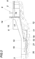
- An inventive low-pressure hydroelectric power plant comprises according to Fig. 1 and 2 a weir 1 between the upper water 2 and the underwater 3.
- a Kaplan turbine 4 is acted upon, which is housed with the generator 5 driven by it in a machine housing 6.
- an inlet guard 9 is arranged in the inlet 7 for the Kaplan turbine 4, which is preceded by an inlet rake 8.
- the connected to the Kaplan turbine 4 intake manifold for the intake water 10 is denoted by 11.
- an ejector ramp 12 for above water.
- the over-water accelerating on the ejector ramp 12 to an over-water jet 13 is controlled by a contactor 14 upstream of the ejector ramp 12 which leaves a passage 17 for the over-water between the lower edge of the protective panel 15 and the threshold 16 of the weir formed by the contactor 14.
- Fig. 1 can be removed, the suction channel 11 extends in a plan view at an acute angle to the longitudinal direction of the Ejektorrampe 12, to then open parallel to the Ejektorrampe 12 below this.
- the direction of emerging from the outlet 18 of the suction pipe 11 driving water 10 coincides with the direction of the ejector ramp 12 leaving overwater jet 13 together.
- the excess water jet 13 thus combines with the shoot water 10 to the total outflow 19th
- the sole 20 of the underwater 3 in the connection area to the suction tube 11 and the ejector ramp 12 is provided with a recess 21 which communicates with a corresponding Distance from the outlet 18 of the suction tube 11 along the union path for the over-water jet 13 with the shoot water 10 extends over the sole width, so that the sole 20 in the region of the recess 21, a course of the Ejektorimpulses consideration takes what reduces the flow losses and thus leads to a better utilization of the ejector effect.
- the ejector effect depends on the speed of the overjet jet 13 firing from the ejector ramp 12 and thus on the ejection speed of the overwater onto the ejector ramp 12. For this reason, it is recommended to make the passage 17 between the protective panel 15 and the threshold 16 of the weir formed by the contactor 14 in the manner of a Venturi nozzle. This is possible with simple constructive means according to the Fig. 3 in that the lower portion of the protective panel 15 delimiting the passage 17 forms a continuous guide surface 22 for laminar flow deflection.
- the lower portion of the protective panel 15 may be composed of one of the protective panel 15 superior circular cylindrical wall portion 23 and a tangentially adjoining, sloping in the flow direction wall portion 24 which engages under the lower edge of the protective panel 15 as the Fig. 3 can be removed.
- the resulting between the threshold 16 and the guide surface 22 nozzle shape of the passage 17 due to the Venturi effect not only a reduction in the otherwise occurring flow losses, but also an increase in the initial velocity of the excess water jet 13, which entails an increase of the effective Ejektorimpulses.
Landscapes
- Engineering & Computer Science (AREA)
- Chemical & Material Sciences (AREA)
- Combustion & Propulsion (AREA)
- Mechanical Engineering (AREA)
- General Engineering & Computer Science (AREA)
- Jet Pumps And Other Pumps (AREA)
Abstract
Es wird ein Niederdruck-Wasserkraftwerk mit einer Ejektorrampe (12) für einen Überwasserstrahl (13), mit einem an eine Turbine (4) angeschlossenen Saugrohr (11) und mit einer Vereinigungsstrecke für den von der Ejektorrampe (12) abströmenden Überwasserstrahl (13) mit dem unterhalb des Überwasserstrahls (13) aus dem Saugrohr (11) ausströmenden Triebwasser (10) beschrieben. Um die Ejektorwirkung besser nützen zu können, wird vorgeschlagen, dass die Vereinigungsstrecke eine Sohle (20) aufweist, die im Anschluss an den Austritt (18) des Saugrohrs (11) in Strömungsrichtung eine sich über die Sohlenbreite erstreckende Vertiefung (21) bildet.There is a low-pressure hydroelectric power plant with an ejector ramp (12) for an over-water jet (13), with a suction pipe (11) connected to a turbine (4) and with a union path for the over-water jet (13) flowing from the ejector ramp (12) described below the over-water jet (13) from the suction pipe (11) effluent water (10). In order to make better use of the ejector effect, it is proposed that the joining section has a sole (20) which, following the outlet (18) of the suction pipe (11), forms a recess (21) extending over the sole width in the flow direction.
Description
Die Erfindung bezieht sich auf ein Niederdruck-Wasserkraftwerk mit einer Ejektorrampe für einen Überwasserstrahl, mit einem an eine Turbine angeschlossenen Saugrohr und mit einer Vereinigungsstrecke für den von der Ejektorrampe abströmenden Überwasserstrahl mit dem unterhalb des Überwasserstrahls aus dem Saugrohr ausströmenden Triebwasser.The invention relates to a low-pressure hydroelectric power plant with an ejector ramp for an over-water jet, with a suction pipe connected to a turbine and with a union path for the outgoing from the Ejektorrampe over-water jet with the effluent below the over-water jet from the intake manifold water.
Bei Wasserkraftanlagen im Niederdruckbereich reduziert ein Anstieg des Unterwasserpegels sowohl die Fallhöhe als auch den Turbinendurchfluss, was sich insbesondere bei Überwasser bemerkbar macht, das den Gesamtabfluss vergrößert und damit zu einem Anstieg des Unterwasserpegels führt. Um diesem negativen Einfluss entgegenwirken und das Überwasser zur Energiegewinnung nützen zu können, wurde bereits vorgeschlagen (
Der Erfindung liegt somit die Aufgabe zugrunde, ein Niederdruck-Wasserkraftwerk mit einer Ejektorrampe für einen Überwasserstrahl so auszugestalten, dass die Ejektorwirkung des Überwassers auch bei höheren Überwasserraten vorteilhaft genützt werden kann.The invention is therefore based on the object, a low-pressure hydroelectric power plant with an ejector ramp for an over-water jet in such a way that the ejector effect of the surface water can be used advantageously even at higher overwater rates.
Ausgehend von einem Niederdruck-Wasserkraftwerk der eingangs geschilderten Art löst die Erfindung die gestellte Aufgabe dadurch, dass die Vereinigungsstrecke eine Sohle aufweist, die im Anschluss an den Austritt des Saugrohrs in Strömungsrichtung eine sich über die Sohlenbreite erstreckende Vertiefung bildet.Starting from a low-pressure hydroelectric power plant of the type described above, the invention achieves this object by virtue of the fact that the joining path has a sole which, following the outlet of the suction pipe, forms a depression extending over the sole width.
Durch die Vertiefung der Sohle der Vereinigungsstrecke wird die Sohle an die Richtung des Ejektorimpulses mit der Wirkung angepasst, dass eine Einschnürung des Gesamtabflusses vor dem Wechselsprung zwischen dem Schießen und dem Strömen unterbunden und damit die durch die Einschnürung bedingte Durchflussbehinderung vermieden wird, was eine bessere Ausnützung der Ejektorwirkung des Überwasserstrahls erlaubt und damit eine Leistungssteigerung mit sich bringt. So konnte beispielsweise im Modellversuch bei einem der doppelten Triebwassermenge entsprechenden Überwassermenge mithilfe einer erfindungsgemäßen Sohleausbildung im Bereich der Vereinigungsstrecke eine Leistungssteigerung aufgrund der Ejektorwirkung von 17 % auf 22 % ermittelt werden. Die Form und Bemaßung der Vertiefung ist vor allem von der Höhe der Saugrohraustrittsöffnung und der Neigung der Ejektorrampe abhängig.By deepening the sole of the union line, the sole is adjusted to the direction of the ejector pulse with the effect of preventing necking of the total drain prior to the jump between the shooting and the streaming and thus avoiding flow restriction caused by the necking, resulting in better utilization allows the ejector effect of the over-water jet and thus brings an increase in performance. Thus, for example, in the model experiment with an amount of excess water corresponding to twice the quantity of driving water, a power increase due to the ejector effect of 17% to 22% could be determined by means of a sole formation according to the invention in the region of the union line. The shape and dimension of the recess is mainly dependent on the height of Saugrohraustrittsöffnung and the inclination of the ejector ramp.
Um die Ejektorwirkung zusätzlich zu verbessern, kann der Ejektorrampe ein der Höhe nach verstellbares, einen Durchtritt für den Überwasserstrahl freigebendes Schütz vorgeordnet werden, dessen unterer den Durchtritt begrenzender Abschnitt eine stetige Leitfläche zur laminaren Strömungsumlenkung bildet. Zufolge dieser Maßnahme weist der Durchtritt zwischen dem Schütz und der Schwelle des durch das Schütz gebildeten Wehrs eine Düsenform mit einer Venturiwirkung auf, die einerseits die Abströmungsverluste verringert und anderseits die Strömungsgeschwindigkeit auf der Austrittseite des Durchtritts und damit den Ejektorimpuls im Bereich der Vereinigung von Triebwasser und Überwasser und damit die Impulskraft um ca. 5 % erhöht, was sich wiederum positiv auf die Leistungssteigerung auswirkt.In order to additionally improve the ejector effect, the ejector ramp can be preceded by a height-adjustable contactor releasing a passage for the over-water jet, the lower passage of which delimits the passage forming a continuous guide surface for laminar flow deflection. According to this measure, the passage between the contactor and the threshold of the weir formed by the contactor on a nozzle shape with a venturi effect, on the one hand reduces the Abströmungsverluste and on the other hand, the flow velocity on the exit side of the passage and thus the Ejektorimpuls in the field of water and Above water and thus the impulse force increased by about 5%, which in turn has a positive effect on the increase in performance.
Besonders einfache Konstruktionsverhältnisse ergeben sich in diesem Zusammenhang, wenn der die stetige Leitfläche bildende Abschnitt des Schützes aus einem kreiszylindrischen Wandabschnitt und einem davon in Strömungsrichtung tangential abfallenden Wandabschnitt zusammengesetzt ist, weil in diesem Fall herkömmliche Schütztafeln in einfacher Art durch das Vorsetzen eines entsprechenden kreiszylindrischen Wandabschnitts und das Anordnen eines ebenen Wandabschnitts umgerüstet werden können, der tangential an den kreiszylindrischen Wandabschnitt anschließt und die Unterkante der Schütztafel untergreift.Particularly simple construction conditions arise in this context when the continuous guide surface forming portion of the contactor is composed of a circular cylindrical wall portion and one of them tangentially sloping wall portion in the flow direction, because in this case conventional Schößafeln in a simple way by the Vorsetzen a corresponding circular cylindrical wall portion and the arrangement of a flat wall section can be converted, which connects tangentially to the circular cylindrical wall section and engages under the lower edge of the protective panel.
In der Zeichnung ist der Erfindungsgegenstand beispielsweise dargestellt. Es zeigen
- Fig. 1
- ein erfindungsgemäßes Niederdruck-Wasserkraftwerk in einer zum Teil aufgerissenen schematischen Draufsicht,
- Fig. 2
- dieses Niederdruck-Wasserkraftwerk in einem schematischen Schnitt nach der Linie II-II der
Fig. 1 und - Fig. 3
- einen vertikalen Schnitt durch das den Durchtritt zur Ejektorrampe freigebenden Schütz in einem größeren Maßstab.
- Fig. 1
- an inventive low-pressure hydroelectric power plant in a partially torn schematic plan view,
- Fig. 2
- this low-pressure hydropower plant in a schematic section along the line II-II of
Fig. 1 and - Fig. 3
- a vertical section through the contactor releasing the ejector ramp on a larger scale.
Ein erfindungsgemäßes Niederdruck-Wasserkraftwerk umfasst nach den
Wie der
Damit bei höheren Anteilen an Überwasser eine Einschnürung des Gesamtabflusses 19 vor einem eine Deckwalze ausbildenden Wechselsprung unterbunden werden kann, ist die Sohle 20 des Unterwassers 3 im Anschlussbereich an das Saugrohr 11 bzw. die Ejektorrampe 12 mit einer Vertiefung 21 versehen, die sich mit einem entsprechenden Abstand vom Austritt 18 des Saugrohrs 11 entlang der Vereinigungsstrecke für den Überwasserstrahl 13 mit dem Triebwasser 10 über die Sohlenbreite erstreckt, sodass die Sohle 20 im Bereich der Vertiefung 21 einen die Richtung des Ejektorimpulses berücksichtigenden Verlauf einnimmt, was die Strömungsverluste verringert und damit zu einer besseren Ausnützung der Ejektorwirkung führt.So that at higher levels of excess water a constriction of the
Die Ejektorwirkung hängt von der Geschwindigkeit des von der Ejektorrampe 12 abschießenden Überwasserstrahls 13 und damit von der Einlaufgeschwindigkeit des Überwassers auf die Ejektorrampe 12 ab. Aus diesem Grund empfiehlt es sich, den Durchtritt 17 zwischen der Schütztafel 15 und der Schwelle 16 des durch das Schütz 14 gebildeten Wehrs nach Art einer Venturidüse zu gestalten. Dies gelingt mit einfachen konstruktiven Mitteln gemäß der
Claims (3)
Applications Claiming Priority (1)
| Application Number | Priority Date | Filing Date | Title |
|---|---|---|---|
| ATA50859/2016A AT519155B1 (en) | 2016-09-27 | 2016-09-27 | Low pressure hydropower plant with an ejector ramp for a surface water jet |
Publications (2)
| Publication Number | Publication Date |
|---|---|
| EP3299611A1 true EP3299611A1 (en) | 2018-03-28 |
| EP3299611B1 EP3299611B1 (en) | 2019-08-14 |
Family
ID=59969074
Family Applications (1)
| Application Number | Title | Priority Date | Filing Date |
|---|---|---|---|
| EP17193215.5A Active EP3299611B1 (en) | 2016-09-27 | 2017-09-26 | Low pressure hydroelectric power plant with an ejector ramp for a surplus water jet |
Country Status (2)
| Country | Link |
|---|---|
| EP (1) | EP3299611B1 (en) |
| AT (1) | AT519155B1 (en) |
Families Citing this family (1)
| Publication number | Priority date | Publication date | Assignee | Title |
|---|---|---|---|---|
| AT524660B1 (en) | 2021-04-01 | 2022-08-15 | Hydro Construct Unternehmen Fuer Wasser Und Energietechnik Ges M B H | hose weir |
Citations (1)
| Publication number | Priority date | Publication date | Assignee | Title |
|---|---|---|---|---|
| WO2002081905A1 (en) * | 2001-04-08 | 2002-10-17 | Peter Roth | Moveable, over-flowable and under-flowable hydro-electric power plant |
Family Cites Families (1)
| Publication number | Priority date | Publication date | Assignee | Title |
|---|---|---|---|---|
| DE102013019652A1 (en) * | 2013-09-30 | 2015-04-02 | Dieter Mühlenbruch | Hydroelectric power station |
-
2016
- 2016-09-27 AT ATA50859/2016A patent/AT519155B1/en active
-
2017
- 2017-09-26 EP EP17193215.5A patent/EP3299611B1/en active Active
Patent Citations (1)
| Publication number | Priority date | Publication date | Assignee | Title |
|---|---|---|---|---|
| WO2002081905A1 (en) * | 2001-04-08 | 2002-10-17 | Peter Roth | Moveable, over-flowable and under-flowable hydro-electric power plant |
Non-Patent Citations (2)
| Title |
|---|
| RUDOLF FRITSCH ET AL: "Ejektorwirkung bei Überwasser mit Vertikaler Kaplan-Turbine", WASSERWIRTSCHAFT, 31 October 2015 (2015-10-31), XP055447561, Retrieved from the Internet <URL:https://www.researchgate.net/profile/Juergen_Schiffer/publication/284498634_Ejektorwirkung_bei_Uberwasser_mit_Vertikaler_Kaplan-Turbine/links/5654286408aefe619b19aac4/Ejektorwirkung-bei-Ueberwasser-mit-Vertikaler-Kaplan-Turbine.pdf> [retrieved on 20180205] * |
| SABRI DENIZ ET AL: "Saugrohre bei Flusskraftwerken", 31 October 2015 (2015-10-31), XP055446328, Retrieved from the Internet <URL:https://www.ethz.ch/content/dam/ethz/special-interest/baug/vaw/vaw-dam/documents/das-institut/mitteilungen/1990-1999/106.pdf> * |
Also Published As
| Publication number | Publication date |
|---|---|
| AT519155A1 (en) | 2018-04-15 |
| AT519155B1 (en) | 2020-01-15 |
| EP3299611B1 (en) | 2019-08-14 |
Similar Documents
| Publication | Publication Date | Title |
|---|---|---|
| DE2222594A1 (en) | SWIMMING POOL WITH CIRCULATING CURRENT | |
| EP3299611B1 (en) | Low pressure hydroelectric power plant with an ejector ramp for a surplus water jet | |
| EP2691636B1 (en) | Weir plant | |
| WO2010017869A2 (en) | Energy recovery device and method for design | |
| EP2578319B1 (en) | Sprinkler head | |
| DE3002578C2 (en) | Device for degassing a liquid | |
| AT516173B1 (en) | Device for air humidification in an air duct | |
| DE102010037926A1 (en) | Hydroelectric power plant for obtaining constantness of running water bodies for fish fauna, has fish ladder device comprising water flowable channel, where channel outlet of ladder device changes into moving passage | |
| CN109235626B (en) | Box-type bidirectional runner with built-in special-shaped thin plate type backflow eliminating device | |
| AT524660B1 (en) | hose weir | |
| DE202007004375U1 (en) | Funnel for bundling of stream energy for e.g. wind power plant, has opening, where specified percentages of inflow air and/or water flow through openings and exit opening, and guiding point provided behind openings for dividing flow | |
| CN115369815B (en) | Energy dissipation structure with various flood discharge energy dissipation modes and energy dissipation method | |
| EP3425117B1 (en) | Device for producing a dotation flow for a fish ladder | |
| DE102020113166A1 (en) | Hydroelectric power station with water sports facility | |
| DE102013019652A1 (en) | Hydroelectric power station | |
| DE214873C (en) | ||
| DE2516797C2 (en) | Nozzle printer, especially in an inkjet writing mechanism | |
| DE848625C (en) | Defense body provided with passage openings | |
| EP1988010B1 (en) | Ship with openings to allow media to flow away | |
| DE205934C (en) | ||
| DE454415C (en) | Device for diverting runoff water from hydropower machines or pumps | |
| DE848682T1 (en) | ENGINE | |
| DE2429538A1 (en) | Energy utilisation from water power with pelton turbine - using normal water flow, reduction pipes, suitable for boat propulsion unit | |
| DE356294C (en) | Steam drainer | |
| DE102018000530A1 (en) | waterworks |
Legal Events
| Date | Code | Title | Description |
|---|---|---|---|
| PUAI | Public reference made under article 153(3) epc to a published international application that has entered the european phase |
Free format text: ORIGINAL CODE: 0009012 |
|
| STAA | Information on the status of an ep patent application or granted ep patent |
Free format text: STATUS: THE APPLICATION HAS BEEN PUBLISHED |
|
| AK | Designated contracting states |
Kind code of ref document: A1 Designated state(s): AL AT BE BG CH CY CZ DE DK EE ES FI FR GB GR HR HU IE IS IT LI LT LU LV MC MK MT NL NO PL PT RO RS SE SI SK SM TR |
|
| AX | Request for extension of the european patent |
Extension state: BA ME |
|
| STAA | Information on the status of an ep patent application or granted ep patent |
Free format text: STATUS: REQUEST FOR EXAMINATION WAS MADE |
|
| 17P | Request for examination filed |
Effective date: 20180921 |
|
| RBV | Designated contracting states (corrected) |
Designated state(s): AL AT BE BG CH CY CZ DE DK EE ES FI FR GB GR HR HU IE IS IT LI LT LU LV MC MK MT NL NO PL PT RO RS SE SI SK SM TR |
|
| GRAP | Despatch of communication of intention to grant a patent |
Free format text: ORIGINAL CODE: EPIDOSNIGR1 |
|
| STAA | Information on the status of an ep patent application or granted ep patent |
Free format text: STATUS: GRANT OF PATENT IS INTENDED |
|
| INTG | Intention to grant announced |
Effective date: 20190405 |
|
| GRAS | Grant fee paid |
Free format text: ORIGINAL CODE: EPIDOSNIGR3 |
|
| GRAA | (expected) grant |
Free format text: ORIGINAL CODE: 0009210 |
|
| STAA | Information on the status of an ep patent application or granted ep patent |
Free format text: STATUS: THE PATENT HAS BEEN GRANTED |
|
| AK | Designated contracting states |
Kind code of ref document: B1 Designated state(s): AL AT BE BG CH CY CZ DE DK EE ES FI FR GB GR HR HU IE IS IT LI LT LU LV MC MK MT NL NO PL PT RO RS SE SI SK SM TR |
|
| REG | Reference to a national code |
Ref country code: GB Ref legal event code: FG4D Free format text: NOT ENGLISH |
|
| REG | Reference to a national code |
Ref country code: CH Ref legal event code: EP Ref country code: AT Ref legal event code: REF Ref document number: 1167328 Country of ref document: AT Kind code of ref document: T Effective date: 20190815 |
|
| REG | Reference to a national code |
Ref country code: DE Ref legal event code: R096 Ref document number: 502017002023 Country of ref document: DE |
|
| REG | Reference to a national code |
Ref country code: CH Ref legal event code: NV Representative=s name: E. BLUM AND CO. AG PATENT- UND MARKENANWAELTE , CH |
|
| REG | Reference to a national code |
Ref country code: IE Ref legal event code: FG4D Free format text: LANGUAGE OF EP DOCUMENT: GERMAN |
|
| REG | Reference to a national code |
Ref country code: NL Ref legal event code: MP Effective date: 20190814 |
|
| REG | Reference to a national code |
Ref country code: LT Ref legal event code: MG4D |
|
| PG25 | Lapsed in a contracting state [announced via postgrant information from national office to epo] |
Ref country code: FI Free format text: LAPSE BECAUSE OF FAILURE TO SUBMIT A TRANSLATION OF THE DESCRIPTION OR TO PAY THE FEE WITHIN THE PRESCRIBED TIME-LIMIT Effective date: 20190814 Ref country code: SE Free format text: LAPSE BECAUSE OF FAILURE TO SUBMIT A TRANSLATION OF THE DESCRIPTION OR TO PAY THE FEE WITHIN THE PRESCRIBED TIME-LIMIT Effective date: 20190814 Ref country code: NO Free format text: LAPSE BECAUSE OF FAILURE TO SUBMIT A TRANSLATION OF THE DESCRIPTION OR TO PAY THE FEE WITHIN THE PRESCRIBED TIME-LIMIT Effective date: 20191114 Ref country code: NL Free format text: LAPSE BECAUSE OF FAILURE TO SUBMIT A TRANSLATION OF THE DESCRIPTION OR TO PAY THE FEE WITHIN THE PRESCRIBED TIME-LIMIT Effective date: 20190814 Ref country code: BG Free format text: LAPSE BECAUSE OF FAILURE TO SUBMIT A TRANSLATION OF THE DESCRIPTION OR TO PAY THE FEE WITHIN THE PRESCRIBED TIME-LIMIT Effective date: 20191114 Ref country code: LT Free format text: LAPSE BECAUSE OF FAILURE TO SUBMIT A TRANSLATION OF THE DESCRIPTION OR TO PAY THE FEE WITHIN THE PRESCRIBED TIME-LIMIT Effective date: 20190814 Ref country code: HR Free format text: LAPSE BECAUSE OF FAILURE TO SUBMIT A TRANSLATION OF THE DESCRIPTION OR TO PAY THE FEE WITHIN THE PRESCRIBED TIME-LIMIT Effective date: 20190814 Ref country code: PT Free format text: LAPSE BECAUSE OF FAILURE TO SUBMIT A TRANSLATION OF THE DESCRIPTION OR TO PAY THE FEE WITHIN THE PRESCRIBED TIME-LIMIT Effective date: 20191216 |
|
| PG25 | Lapsed in a contracting state [announced via postgrant information from national office to epo] |
Ref country code: IS Free format text: LAPSE BECAUSE OF FAILURE TO SUBMIT A TRANSLATION OF THE DESCRIPTION OR TO PAY THE FEE WITHIN THE PRESCRIBED TIME-LIMIT Effective date: 20191214 Ref country code: RS Free format text: LAPSE BECAUSE OF FAILURE TO SUBMIT A TRANSLATION OF THE DESCRIPTION OR TO PAY THE FEE WITHIN THE PRESCRIBED TIME-LIMIT Effective date: 20190814 Ref country code: GR Free format text: LAPSE BECAUSE OF FAILURE TO SUBMIT A TRANSLATION OF THE DESCRIPTION OR TO PAY THE FEE WITHIN THE PRESCRIBED TIME-LIMIT Effective date: 20191115 Ref country code: ES Free format text: LAPSE BECAUSE OF FAILURE TO SUBMIT A TRANSLATION OF THE DESCRIPTION OR TO PAY THE FEE WITHIN THE PRESCRIBED TIME-LIMIT Effective date: 20190814 Ref country code: AL Free format text: LAPSE BECAUSE OF FAILURE TO SUBMIT A TRANSLATION OF THE DESCRIPTION OR TO PAY THE FEE WITHIN THE PRESCRIBED TIME-LIMIT Effective date: 20190814 Ref country code: LV Free format text: LAPSE BECAUSE OF FAILURE TO SUBMIT A TRANSLATION OF THE DESCRIPTION OR TO PAY THE FEE WITHIN THE PRESCRIBED TIME-LIMIT Effective date: 20190814 |
|
| PG25 | Lapsed in a contracting state [announced via postgrant information from national office to epo] |
Ref country code: TR Free format text: LAPSE BECAUSE OF FAILURE TO SUBMIT A TRANSLATION OF THE DESCRIPTION OR TO PAY THE FEE WITHIN THE PRESCRIBED TIME-LIMIT Effective date: 20190814 |
|
| PG25 | Lapsed in a contracting state [announced via postgrant information from national office to epo] |
Ref country code: EE Free format text: LAPSE BECAUSE OF FAILURE TO SUBMIT A TRANSLATION OF THE DESCRIPTION OR TO PAY THE FEE WITHIN THE PRESCRIBED TIME-LIMIT Effective date: 20190814 Ref country code: PL Free format text: LAPSE BECAUSE OF FAILURE TO SUBMIT A TRANSLATION OF THE DESCRIPTION OR TO PAY THE FEE WITHIN THE PRESCRIBED TIME-LIMIT Effective date: 20190814 Ref country code: DK Free format text: LAPSE BECAUSE OF FAILURE TO SUBMIT A TRANSLATION OF THE DESCRIPTION OR TO PAY THE FEE WITHIN THE PRESCRIBED TIME-LIMIT Effective date: 20190814 Ref country code: RO Free format text: LAPSE BECAUSE OF FAILURE TO SUBMIT A TRANSLATION OF THE DESCRIPTION OR TO PAY THE FEE WITHIN THE PRESCRIBED TIME-LIMIT Effective date: 20190814 |
|
| PG25 | Lapsed in a contracting state [announced via postgrant information from national office to epo] |
Ref country code: CZ Free format text: LAPSE BECAUSE OF FAILURE TO SUBMIT A TRANSLATION OF THE DESCRIPTION OR TO PAY THE FEE WITHIN THE PRESCRIBED TIME-LIMIT Effective date: 20190814 Ref country code: SK Free format text: LAPSE BECAUSE OF FAILURE TO SUBMIT A TRANSLATION OF THE DESCRIPTION OR TO PAY THE FEE WITHIN THE PRESCRIBED TIME-LIMIT Effective date: 20190814 Ref country code: IS Free format text: LAPSE BECAUSE OF FAILURE TO SUBMIT A TRANSLATION OF THE DESCRIPTION OR TO PAY THE FEE WITHIN THE PRESCRIBED TIME-LIMIT Effective date: 20200224 Ref country code: MC Free format text: LAPSE BECAUSE OF FAILURE TO SUBMIT A TRANSLATION OF THE DESCRIPTION OR TO PAY THE FEE WITHIN THE PRESCRIBED TIME-LIMIT Effective date: 20190814 Ref country code: SM Free format text: LAPSE BECAUSE OF FAILURE TO SUBMIT A TRANSLATION OF THE DESCRIPTION OR TO PAY THE FEE WITHIN THE PRESCRIBED TIME-LIMIT Effective date: 20190814 |
|
| REG | Reference to a national code |
Ref country code: DE Ref legal event code: R097 Ref document number: 502017002023 Country of ref document: DE |
|
| PLBE | No opposition filed within time limit |
Free format text: ORIGINAL CODE: 0009261 |
|
| STAA | Information on the status of an ep patent application or granted ep patent |
Free format text: STATUS: NO OPPOSITION FILED WITHIN TIME LIMIT |
|
| PG2D | Information on lapse in contracting state deleted |
Ref country code: IS |
|
| PG25 | Lapsed in a contracting state [announced via postgrant information from national office to epo] |
Ref country code: IE Free format text: LAPSE BECAUSE OF NON-PAYMENT OF DUE FEES Effective date: 20190926 Ref country code: LU Free format text: LAPSE BECAUSE OF NON-PAYMENT OF DUE FEES Effective date: 20190926 |
|
| REG | Reference to a national code |
Ref country code: BE Ref legal event code: MM Effective date: 20190930 |
|
| 26N | No opposition filed |
Effective date: 20200603 |
|
| PG25 | Lapsed in a contracting state [announced via postgrant information from national office to epo] |
Ref country code: SI Free format text: LAPSE BECAUSE OF FAILURE TO SUBMIT A TRANSLATION OF THE DESCRIPTION OR TO PAY THE FEE WITHIN THE PRESCRIBED TIME-LIMIT Effective date: 20190814 Ref country code: BE Free format text: LAPSE BECAUSE OF NON-PAYMENT OF DUE FEES Effective date: 20190930 |
|
| PG25 | Lapsed in a contracting state [announced via postgrant information from national office to epo] |
Ref country code: CY Free format text: LAPSE BECAUSE OF FAILURE TO SUBMIT A TRANSLATION OF THE DESCRIPTION OR TO PAY THE FEE WITHIN THE PRESCRIBED TIME-LIMIT Effective date: 20190814 |
|
| PG25 | Lapsed in a contracting state [announced via postgrant information from national office to epo] |
Ref country code: MT Free format text: LAPSE BECAUSE OF FAILURE TO SUBMIT A TRANSLATION OF THE DESCRIPTION OR TO PAY THE FEE WITHIN THE PRESCRIBED TIME-LIMIT Effective date: 20190814 Ref country code: HU Free format text: LAPSE BECAUSE OF FAILURE TO SUBMIT A TRANSLATION OF THE DESCRIPTION OR TO PAY THE FEE WITHIN THE PRESCRIBED TIME-LIMIT; INVALID AB INITIO Effective date: 20170926 |
|
| PG25 | Lapsed in a contracting state [announced via postgrant information from national office to epo] |
Ref country code: MK Free format text: LAPSE BECAUSE OF FAILURE TO SUBMIT A TRANSLATION OF THE DESCRIPTION OR TO PAY THE FEE WITHIN THE PRESCRIBED TIME-LIMIT Effective date: 20190814 |
|
| PGFP | Annual fee paid to national office [announced via postgrant information from national office to epo] |
Ref country code: IT Payment date: 20230920 Year of fee payment: 7 Ref country code: GB Payment date: 20230926 Year of fee payment: 7 |
|
| REG | Reference to a national code |
Ref country code: AT Ref legal event code: MM01 Ref document number: 1167328 Country of ref document: AT Kind code of ref document: T Effective date: 20220926 |
|
| PGFP | Annual fee paid to national office [announced via postgrant information from national office to epo] |
Ref country code: FR Payment date: 20230926 Year of fee payment: 7 Ref country code: DE Payment date: 20230928 Year of fee payment: 7 |
|
| PG25 | Lapsed in a contracting state [announced via postgrant information from national office to epo] |
Ref country code: AT Free format text: LAPSE BECAUSE OF NON-PAYMENT OF DUE FEES Effective date: 20220926 |
|
| PGFP | Annual fee paid to national office [announced via postgrant information from national office to epo] |
Ref country code: CH Payment date: 20231001 Year of fee payment: 7 |