EP3299582A1 - Sealing arrangement and gas turbine comprising a sealing arrangement - Google Patents
Sealing arrangement and gas turbine comprising a sealing arrangement Download PDFInfo
- Publication number
- EP3299582A1 EP3299582A1 EP17191919.4A EP17191919A EP3299582A1 EP 3299582 A1 EP3299582 A1 EP 3299582A1 EP 17191919 A EP17191919 A EP 17191919A EP 3299582 A1 EP3299582 A1 EP 3299582A1
- Authority
- EP
- European Patent Office
- Prior art keywords
- leaf
- outer seal
- main body
- seal
- extension
- Prior art date
- Legal status (The legal status is an assumption and is not a legal conclusion. Google has not performed a legal analysis and makes no representation as to the accuracy of the status listed.)
- Granted
Links
Images



Classifications
-
- F—MECHANICAL ENGINEERING; LIGHTING; HEATING; WEAPONS; BLASTING
- F23—COMBUSTION APPARATUS; COMBUSTION PROCESSES
- F23R—GENERATING COMBUSTION PRODUCTS OF HIGH PRESSURE OR HIGH VELOCITY, e.g. GAS-TURBINE COMBUSTION CHAMBERS
- F23R3/00—Continuous combustion chambers using liquid or gaseous fuel
-
- F—MECHANICAL ENGINEERING; LIGHTING; HEATING; WEAPONS; BLASTING
- F01—MACHINES OR ENGINES IN GENERAL; ENGINE PLANTS IN GENERAL; STEAM ENGINES
- F01D—NON-POSITIVE DISPLACEMENT MACHINES OR ENGINES, e.g. STEAM TURBINES
- F01D9/00—Stators
- F01D9/02—Nozzles; Nozzle boxes; Stator blades; Guide conduits, e.g. individual nozzles
- F01D9/023—Transition ducts between combustor cans and first stage of the turbine in gas-turbine engines; their cooling or sealings
-
- F—MECHANICAL ENGINEERING; LIGHTING; HEATING; WEAPONS; BLASTING
- F01—MACHINES OR ENGINES IN GENERAL; ENGINE PLANTS IN GENERAL; STEAM ENGINES
- F01D—NON-POSITIVE DISPLACEMENT MACHINES OR ENGINES, e.g. STEAM TURBINES
- F01D9/00—Stators
- F01D9/02—Nozzles; Nozzle boxes; Stator blades; Guide conduits, e.g. individual nozzles
- F01D9/04—Nozzles; Nozzle boxes; Stator blades; Guide conduits, e.g. individual nozzles forming ring or sector
-
- F—MECHANICAL ENGINEERING; LIGHTING; HEATING; WEAPONS; BLASTING
- F02—COMBUSTION ENGINES; HOT-GAS OR COMBUSTION-PRODUCT ENGINE PLANTS
- F02C—GAS-TURBINE PLANTS; AIR INTAKES FOR JET-PROPULSION PLANTS; CONTROLLING FUEL SUPPLY IN AIR-BREATHING JET-PROPULSION PLANTS
- F02C3/00—Gas-turbine plants characterised by the use of combustion products as the working fluid
- F02C3/04—Gas-turbine plants characterised by the use of combustion products as the working fluid having a turbine driving a compressor
-
- F—MECHANICAL ENGINEERING; LIGHTING; HEATING; WEAPONS; BLASTING
- F02—COMBUSTION ENGINES; HOT-GAS OR COMBUSTION-PRODUCT ENGINE PLANTS
- F02C—GAS-TURBINE PLANTS; AIR INTAKES FOR JET-PROPULSION PLANTS; CONTROLLING FUEL SUPPLY IN AIR-BREATHING JET-PROPULSION PLANTS
- F02C7/00—Features, components parts, details or accessories, not provided for in, or of interest apart form groups F02C1/00 - F02C6/00; Air intakes for jet-propulsion plants
- F02C7/28—Arrangement of seals
-
- F—MECHANICAL ENGINEERING; LIGHTING; HEATING; WEAPONS; BLASTING
- F16—ENGINEERING ELEMENTS AND UNITS; GENERAL MEASURES FOR PRODUCING AND MAINTAINING EFFECTIVE FUNCTIONING OF MACHINES OR INSTALLATIONS; THERMAL INSULATION IN GENERAL
- F16J—PISTONS; CYLINDERS; SEALINGS
- F16J15/00—Sealings
- F16J15/16—Sealings between relatively-moving surfaces
-
- F—MECHANICAL ENGINEERING; LIGHTING; HEATING; WEAPONS; BLASTING
- F05—INDEXING SCHEMES RELATING TO ENGINES OR PUMPS IN VARIOUS SUBCLASSES OF CLASSES F01-F04
- F05D—INDEXING SCHEME FOR ASPECTS RELATING TO NON-POSITIVE-DISPLACEMENT MACHINES OR ENGINES, GAS-TURBINES OR JET-PROPULSION PLANTS
- F05D2220/00—Application
- F05D2220/30—Application in turbines
- F05D2220/32—Application in turbines in gas turbines
-
- F—MECHANICAL ENGINEERING; LIGHTING; HEATING; WEAPONS; BLASTING
- F23—COMBUSTION APPARATUS; COMBUSTION PROCESSES
- F23R—GENERATING COMBUSTION PRODUCTS OF HIGH PRESSURE OR HIGH VELOCITY, e.g. GAS-TURBINE COMBUSTION CHAMBERS
- F23R2900/00—Special features of, or arrangements for continuous combustion chambers; Combustion processes therefor
- F23R2900/00012—Details of sealing devices
Definitions
- the subject matter disclosed herein relates to a combustor for a gas turbine. More specifically, the disclosure is directed to a sealing arrangement for the interface of one or more combustor transition ducts with one or more inlets of a first stage nozzle of a gas turbine.
- Gas turbines typically comprise several interconnected discrete parts.
- a gas turbine generally includes an inlet section, a compression section, a plurality of combustors, a turbine section, and an exhaust section.
- the inlet section may include a series of filters, cooling coils, moisture separators, and/or other devices to purify and otherwise condition a working fluid (e.g., air) entering the gas turbine.
- the working fluid flows downstream from the inlet section to a compressor section where kinetic energy is progressively imparted to the working fluid to produce a compressed working fluid at a highly energized state.
- the compressed working fluid is mixed with a fuel from a fuel supply to form a combustible mixture within one or more combustors.
- the combustible mixture is burned to produce combustion gases having a high temperature and pressure.
- the combustion gases flow through a turbine of a turbine section wherein energy (kinetic and/or thermal) is transferred from the combustion gases to rotor blades, thus causing a shaft to rotate and produce work.
- the rotation of the turbine shaft may drive the compressor to produce the compressed working fluid.
- the shaft may connect the turbine to a generator for producing electricity.
- Exhaust gases from the turbine flow through an exhaust section that connects the turbine to an exhaust stack downstream from the turbine.
- the exhaust section may include, for example, a heat recovery steam generator for cleaning and extracting additional heat from the exhaust gases prior to release to the environment.
- the combustors of a gas turbine are generally connected to the inlets of a first stage nozzle of the turbine section via transition ducts.
- each transition duct has an aft frame downstream of the combustor which connects to an inlet of the turbine section.
- the aft frame will usually have two arcuate portions which are typically referred to as inner and outer portions, being inner and outer in the radial direction with respect to the centerline axis of the turbine.
- the inner and outer portions of the aft frame are interconnected by radially extending linear portions, often referred to as side portions.
- Inner and outer circumferential seals are used to seal between the inner and outer portions of the aft frame and the corresponding inlet of the turbine section. Radially oriented side seals can be disposed between adjacent aft frames to substantially close and seal off the circumferential gaps between the side portion of one aft frame and the next aft frame.
- the radially oriented side seals between circumferentially adjacent aft frames are axially offset (with reference to the turbine axis) from the inner and outer seals between each aft frame and the inlet. Because of this axial offset, gaps remain between the inner and outer seals and the side seals.
- Gas turbines usually burn hydrocarbon fuels and produce air polluting emissions such as oxides of nitrogen (NOx) and carbon monoxide (CO).
- NOx oxides of nitrogen
- CO carbon monoxide
- gas turbines and associated sealing arrangements which facilitate a reduction or elimination of compressed air bypassing the combustor, working fluid lost to the ambient atmosphere, and/or emissions escaping to the ambient atmosphere would be advantageous.
- the sealing arrangement includes a first outer seal comprising a main body, a circumferentially oriented frame rail, an axially oriented leaf, a frame rail extension that extends circumferentially beyond the main body, and a leaf extension that extends circumferentially beyond the main body.
- the sealing arrangement also includes a second outer seal adjacent to the first outer seal, the second outer seal comprising a main body, a circumferentially oriented frame rail, an axially oriented leaf, a frame rail extension that extends circumferentially beyond the main body, and a leaf extension that extends circumferentially beyond the main body.
- the second outer seal is circumferentially aligned with the first outer seal.
- the sealing arrangement also includes a side seal radially disposed between the first outer seal and the second outer seal.
- the side seal comprising an elongate radially oriented main body, an axially oriented leaf, a projection, and a notch defined by the elongate radially oriented main body, an axial portion of the projection, and a radial portion of the projection.
- the gas turbine includes a central axis.
- the central axis of the gas turbine defines an axial direction, a radial direction perpendicular to the central axis, and a circumferential direction extending around the central axis.
- the gas turbine further comprises a compressor, a turbine comprising a first stage nozzle at an upstream end of the turbine, and a plurality of combustors disposed downstream from the compressor and upstream from the turbine.
- the combustors are spaced along the circumferential direction.
- Each combustor includes an upstream end, a downstream end, a transition duct which defines a flow path from the compressor to the turbine, and an aft frame that circumferentially surrounds the downstream end of the transition duct.
- the aft frame comprising a forward face and an aft face, the aft frame further comprising an inner portion separated from an outer portion along the radial direction, a pair of opposing side portions that extend along the radial direction between the inner portion and the outer portion, a pair of outer corners defined by the intersections of the pair of opposing side portions with the outer portion, and a tab projecting from one of the pair of outer corners.
- a first outer seal is on the outer portion of the aft frame of the transition duct of a first one of the plurality of combustors, the first outer seal comprising a main body, a circumferentially oriented frame rail, an axially oriented leaf, a frame rail extension that extends circumferentially beyond the main body, and a leaf extension that extends circumferentially beyond the main body.
- a second outer seal is on the outer portion of the aft frame of the transition duct of a second one of the plurality of combustors, the second combustor circumferentially adjacent to the first combustor, the second outer seal comprising a main body, a circumferentially oriented frame rail, an axially oriented leaf, a frame rail extension that extends circumferentially beyond the main body, and a leaf extension that extends circumferentially beyond the main body.
- a side seal is radially disposed between the first outer seal and the second outer seal, the side seal comprising an elongate main body defining a height of the side seal along the radial direction, a leaf extending from the main body along the axial direction, a projection, and a notch defined between the elongate main body and the projection.
- upstream refers to the relative direction with respect to fluid flow in a fluid pathway.
- upstream refers to the direction from which the fluid flows
- downstream refers to the direction to which the fluid flows.
- radially refers to the relative direction that is substantially perpendicular to an axial centerline of a particular component
- axially refers to the relative direction that is substantially parallel and/or coaxially aligned to an axial centerline of a particular component
- circumferentially refers to the relative direction that extends around the axial centerline of a particular component.
- FIG. 1 illustrates a schematic diagram of an exemplary gas turbine 10 that may incorporate various embodiments of the present invention.
- the gas turbine 10 generally includes an inlet section 12, a compressor 14 disposed downstream of the inlet section 12, at least one combustor 16 disposed downstream of the compressor 14, a turbine 18 disposed downstream of the combustor 16 and an exhaust section 20 disposed downstream of the turbine 18. Additionally, the gas turbine 10 may include one or more shafts 22 that couple the compressor 14 to the turbine 18.
- air 24 flows through the inlet section 12 and into the compressor 14 where the air 24 is progressively compressed, thus providing compressed air 26 to the combustor 16. At least a portion of the compressed air 26 is mixed with a fuel 28 within the combustor 16 and burned to produce combustion gases 30.
- the combustion gases 30 flow from the combustor 16 into the turbine 18, wherein energy (kinetic and/or thermal) is transferred from the combustion gases 30 to rotor blades (not shown), thus causing shaft 22 to rotate.
- the mechanical rotational energy may then be used for various purposes such as to power the compressor 14 and/or to generate electricity.
- the combustion gases 30 exiting the turbine 18 may then be exhausted from the gas turbine 10 via the exhaust section 20.
- the combustor 16 may be at least partially surrounded by an outer casing 36 such as a compressor discharge casing.
- the outer casing 36 may at least partially define a high pressure plenum 34 that at least partially surrounds various components of the combustor 16, such as transition duct 32.
- the high pressure plenum 34 may be in fluid communication with the compressor 14 ( FIG. 1 ) so as to receive the compressed air 26 therefrom.
- the combustor 16 may be connected to the turbine 18 via a transition duct 32 including an aft frame 100.
- the transition duct 32 defines a flow path P. Also shown in FIG.
- FIG. 2 is the central axis A of turbine 18, which defines an axial direction that is substantially parallel to and/or coaxially aligned with axis A, a radial direction perpendicular to axis A, and a circumferential direction extending around axis A.
- a pair of circumferentially arranged transition ducts 32 are illustrated, each having an aft frame 100 that surrounds its respective downstream end.
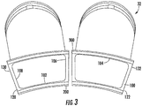
- the aft frame may have an inner portion 102 and an outer portion 104, with a pair of opposing side portions 106 and 108 that extend radially between the inner and the outer portions 102 and 104.
- an inner seal 200 and an outer seal 300 respectively disposed on the inner portion 102 and outer portion 104 of each aft frame 100.
- inner seal 200 and outer seal 300 are circumferentially oriented, each inner seal 200 is circumferentially aligned with the other inner seal 200 on the adjacent aft frame 100, and each outer seal 300 is circumferentially aligned with the other outer seal 300 on the adjacent aft frame 100.
- the aft frame 100 may include a forward face 110 and an aft face 112.
- the intersections of side portions 106 and 108 with inner portion 102 define inner corners 120 and 122, and the intersections of side portions 106 and 108 with outer portion 104 define outer corners 130 and 132.
- a radially oriented side seal 400 is disposed between the aft frames 100 and the inner and outer seals 200 and 300 disposed thereon.
- certain features of the aft frame 100 and seals, 200, 300, and 400 will be described with reference to one or both inner corners 120 and 122, nonetheless, it should be recognized by one of ordinary skill in the art that such features can be associated with any or all of inner corners 120, 122 or outer corners 130, 132.
- FIG. 4 illustrates an outer seal 300 according to at least one embodiment of the present subject matter.
- Outer seal 300 may include a main body 302 which is generally circumferentially coextensive with the outer portion 104 of aft frame 100.
- Main body 302 may include a circumferentially oriented frame rail 304 and an axially oriented leaf 308.
- some embodiments of outer seal 300 may further include a frame rail extension 306 that extends circumferentially beyond the main body 302 and a leaf extension 310 that extends circumferentially beyond the main body 302.
- a deflection limiter 309 may be provided radially inward of leaf extension 310, and in particular a corner extension 307 ( FIG. 5 ) thereof. Deflection limiter 309 reinforces corner extension 307 to avoid or minimize corner extension 307 bending radially inward, away from axial leaf 412 ( FIGS. 8 & 9 ) under pressure from compressed air 26 ( FIG. 2 ).
- outer seal 300 generally comprises primarily a cloth material 312, which can be a woven mesh cloth of a suitable metal material, e.g., alloy L605.
- the cloth material 312 is supported by frame rail 304 and various shims 314.
- the cloth material 312 extends generally axially away from the frame rail 304 in the aft direction, such that cloth material 312 and supporting shim 314 form axially oriented leaf 308.
- FIGS. 6 and 7 illustrate an exemplary side seal 400 which may be radially disposed between adjacent aft frames 100 (see, e.g., FIG. 3 ), and in particular the outer seals 300 thereon.
- the side seal 400 may include an elongate radially oriented main body 402, with a projection 404 extending from the main body 402 on the aft side of main body 402.
- projection 404 may in some embodiments include an axial portion 406 and a radial portion 408. Also as shown, e.g., in FIG.
- a notch 410 maybe defined between main body 402 and projection 404, and in particular between main body 402 and the axial portion 406 and the radial portion 408 of projection 404.
- the side seal 400 may further include an axially oriented leaf 412, and the leaf 412 may extend from the radial portion 408 of the projection 404.
- Axial leaf 412 may be constructed of a cloth material 416 with supporting shim 418, similar to outer seal 300 as described above.
- Axial leaf 412 may further include an exterior laminate 414 of similar material as the internal supporting shim 418.
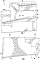
- FIG. 8 illustrates an exemplary sealing arrangement incorporating features of at least one embodiment of the present subject matter.
- the view of FIG. 8 is looking radially outward, which may more generally be characterized as looking up at the bottom of outer seals 300 and leaf 412 of side seal 400.
- one or more of aft frames 100 may include a tab 134 projecting from one or more of outer corners 130, 132.
- a circumferential installation clearance X may be maintained between adjacent outer seals 300.
- tabs 134 abut frame rail extensions 306 to at least partially occlude flow around the outer corners 130, 132.
- the gap arising from circumferential installation clearance X may be at least partially occluded by the overlapping arrangement of axially oriented leaf 412 and leaf extensions 310.
- FIG. 9 illustrates a perspective view of an exemplary sealing arrangement according to at least one embodiment of the present subject matter.
- the view of FIG. 9 is looking radially inward, which may more generally be characterized as looking down at the top of outer seals 300 and side seal 400.
- the adjacent outer seals 300 and side seal 400 cooperate to at least substantially occlude circumferential installation clearance X between adjacent aft frames 100.
- each frame rail extension 306 and each leaf extension 310 extends towards the corresponding frame rail extension 306 and leaf extension 310 on the adjacent outer seal 300. Also illustrated in FIG.
- each of the frame rail extensions 306 on adjacent outer seals 300 may be slideably received within the notch 410 in the side seal 400 such that the portion of circumferential installation clearance X between the frame rail extensions 306 is at least substantially occluded. Further, in embodiments wherein the frame rail extensions 306 are slideably received within the notch 410, thermal expansion and contraction, as well as operation vibration, and other relative movement may be accommodated by the slideably nature of this connection Further illustrated for example in FIG.
- the axially oriented leaf 412 extends from projection 404 such that when the sealing arrangement is assembled the axially oriented leaf 412 of the side seal 400 overlaps the leaf extensions 310 on the adjacent outer seals 300, and at least substantially occludes the portion of circumferential installation clearance X between the adjacent leaf extensions 310.
Landscapes
- Engineering & Computer Science (AREA)
- General Engineering & Computer Science (AREA)
- Mechanical Engineering (AREA)
- Chemical & Material Sciences (AREA)
- Combustion & Propulsion (AREA)
- Turbine Rotor Nozzle Sealing (AREA)
Abstract
Description
- The subject matter disclosed herein relates to a combustor for a gas turbine. More specifically, the disclosure is directed to a sealing arrangement for the interface of one or more combustor transition ducts with one or more inlets of a first stage nozzle of a gas turbine.
- Gas turbines typically comprise several interconnected discrete parts. A gas turbine generally includes an inlet section, a compression section, a plurality of combustors, a turbine section, and an exhaust section. The inlet section may include a series of filters, cooling coils, moisture separators, and/or other devices to purify and otherwise condition a working fluid (e.g., air) entering the gas turbine. The working fluid flows downstream from the inlet section to a compressor section where kinetic energy is progressively imparted to the working fluid to produce a compressed working fluid at a highly energized state. The compressed working fluid is mixed with a fuel from a fuel supply to form a combustible mixture within one or more combustors. The combustible mixture is burned to produce combustion gases having a high temperature and pressure. The combustion gases flow through a turbine of a turbine section wherein energy (kinetic and/or thermal) is transferred from the combustion gases to rotor blades, thus causing a shaft to rotate and produce work. For example, the rotation of the turbine shaft may drive the compressor to produce the compressed working fluid. Alternately or in addition, the shaft may connect the turbine to a generator for producing electricity. Exhaust gases from the turbine flow through an exhaust section that connects the turbine to an exhaust stack downstream from the turbine. The exhaust section may include, for example, a heat recovery steam generator for cleaning and extracting additional heat from the exhaust gases prior to release to the environment.
- The combustors of a gas turbine are generally connected to the inlets of a first stage nozzle of the turbine section via transition ducts. Typically, each transition duct has an aft frame downstream of the combustor which connects to an inlet of the turbine section. The aft frame will usually have two arcuate portions which are typically referred to as inner and outer portions, being inner and outer in the radial direction with respect to the centerline axis of the turbine. The inner and outer portions of the aft frame are interconnected by radially extending linear portions, often referred to as side portions. Inner and outer circumferential seals are used to seal between the inner and outer portions of the aft frame and the corresponding inlet of the turbine section. Radially oriented side seals can be disposed between adjacent aft frames to substantially close and seal off the circumferential gaps between the side portion of one aft frame and the next aft frame.
- The radially oriented side seals between circumferentially adjacent aft frames are axially offset (with reference to the turbine axis) from the inner and outer seals between each aft frame and the inlet. Because of this axial offset, gaps remain between the inner and outer seals and the side seals. Gas turbines usually burn hydrocarbon fuels and produce air polluting emissions such as oxides of nitrogen (NOx) and carbon monoxide (CO). Thus, gaps between the inner and outer seals and the side seals may lead to escape of working fluid (e.g., compressed air and/or combustion gases) flowing through the transition duct from the combustor to the first stage nozzle, which can cause lower performance and a shift in the emission of air pollutants.
- Aspects and advantages are set forth below in the following description, or may be obvious from the description, or may be learned through practice.
- Improved sealing connections between the various parts of the gas turbine are desired in the art. In particular, gas turbines and associated sealing arrangements which facilitate a reduction or elimination of compressed air bypassing the combustor, working fluid lost to the ambient atmosphere, and/or emissions escaping to the ambient atmosphere would be advantageous.
- One embodiment of the present disclosure is directed to a sealing arrangement for sealing between a first component and a second component. The sealing arrangement includes a first outer seal comprising a main body, a circumferentially oriented frame rail, an axially oriented leaf, a frame rail extension that extends circumferentially beyond the main body, and a leaf extension that extends circumferentially beyond the main body. The sealing arrangement also includes a second outer seal adjacent to the first outer seal, the second outer seal comprising a main body, a circumferentially oriented frame rail, an axially oriented leaf, a frame rail extension that extends circumferentially beyond the main body, and a leaf extension that extends circumferentially beyond the main body. The second outer seal is circumferentially aligned with the first outer seal. The sealing arrangement also includes a side seal radially disposed between the first outer seal and the second outer seal. The side seal comprising an elongate radially oriented main body, an axially oriented leaf, a projection, and a notch defined by the elongate radially oriented main body, an axial portion of the projection, and a radial portion of the projection.
- Another embodiment is directed to a gas turbine. The gas turbine includes a central axis. The central axis of the gas turbine defines an axial direction, a radial direction perpendicular to the central axis, and a circumferential direction extending around the central axis. The gas turbine further comprises a compressor, a turbine comprising a first stage nozzle at an upstream end of the turbine, and a plurality of combustors disposed downstream from the compressor and upstream from the turbine. The combustors are spaced along the circumferential direction. Each combustor includes an upstream end, a downstream end, a transition duct which defines a flow path from the compressor to the turbine, and an aft frame that circumferentially surrounds the downstream end of the transition duct. The aft frame comprising a forward face and an aft face, the aft frame further comprising an inner portion separated from an outer portion along the radial direction, a pair of opposing side portions that extend along the radial direction between the inner portion and the outer portion, a pair of outer corners defined by the intersections of the pair of opposing side portions with the outer portion, and a tab projecting from one of the pair of outer corners. A first outer seal is on the outer portion of the aft frame of the transition duct of a first one of the plurality of combustors, the first outer seal comprising a main body, a circumferentially oriented frame rail, an axially oriented leaf, a frame rail extension that extends circumferentially beyond the main body, and a leaf extension that extends circumferentially beyond the main body. A second outer seal is on the outer portion of the aft frame of the transition duct of a second one of the plurality of combustors, the second combustor circumferentially adjacent to the first combustor, the second outer seal comprising a main body, a circumferentially oriented frame rail, an axially oriented leaf, a frame rail extension that extends circumferentially beyond the main body, and a leaf extension that extends circumferentially beyond the main body. A side seal is radially disposed between the first outer seal and the second outer seal, the side seal comprising an elongate main body defining a height of the side seal along the radial direction, a leaf extending from the main body along the axial direction, a projection, and a notch defined between the elongate main body and the projection.
- Those of ordinary skill in the art will better appreciate the features and aspects of such embodiments, and others, upon review of the specification.
- A full and enabling disclosure of the of various embodiments, including the best mode thereof to one skilled in the art, is set forth more particularly in the remainder of the specification, including reference to the accompanying figures, in which:
-
FIG. 1 illustrates a schematic diagram of an exemplary gas turbine that may incorporate various embodiments of the present disclosure; -
FIG. 2 illustrates a section view of a transition duct between a combustor and an inlet according to at least one embodiment; -
FIG. 3 is a perspective view of circumferentially adjacent aft frames; -
FIG. 4 is a perspective view of an outer seal according to at least one embodiment; -
FIG. 5 is a perspective view of an outer seal according to at least one embodiment; -
FIG. 6 is a perspective view of a side seal according to at least one embodiment; -
FIG. 7 is a side view of a side seal according to at least one embodiment; -
FIG. 8 is a perspective view of an exemplary sealing arrangement according to at least one embodiment; and -
FIG. 9 is a perspective view of an exemplary sealing arrangement according to at least one embodiment. - Reference will now be made in detail to present embodiments of the disclosure, one or more examples of which are illustrated in the accompanying drawings. The detailed description uses numerical and letter designations to refer to features in the drawings. Like or similar designations in the drawings and description have been used to refer to like or similar parts of the disclosure.
- As used herein, the terms "first," "second," and "third" maybe used interchangeably to distinguish one component from another and are not intended to signify location or importance of the individual components. The terms "upstream" (or "forward") and "downstream" (or "aft") refer to the relative direction with respect to fluid flow in a fluid pathway. For example, "upstream" refers to the direction from which the fluid flows, and "downstream" refers to the direction to which the fluid flows. The term "radially" refers to the relative direction that is substantially perpendicular to an axial centerline of a particular component, the term "axially" refers to the relative direction that is substantially parallel and/or coaxially aligned to an axial centerline of a particular component and the term "circumferentially" refers to the relative direction that extends around the axial centerline of a particular component.
- The terminology used herein is for the purpose of describing particular embodiments only and is not intended to be limiting. As used herein, the singular forms "a," "an," and "the" are intended to include the plural forms as well, unless the context clearly indicates otherwise. It will be further understood that the terms "comprises" and/or "comprising," when used in this specification, specify the presence of stated features, integers, steps, operations, elements, and/or components, but do not preclude the presence or addition of one or more other features, integers, steps, operations, elements, components, and/or groups thereof.
- Each example is provided by way of explanation, not limitation. In fact, it will be apparent to those skilled in the art that modifications and variations can be made without departing from the scope or spirit thereof. For instance, features illustrated or described as part of one embodiment may be used on another embodiment to yield a still further embodiment. Thus, it is intended that the present disclosure covers such modifications and variations as come within the scope of the appended claims and their equivalents. Although exemplary embodiments of the present disclosure will be described generally in the context of a land based power generating gas turbine combustor for purposes of illustration, one of ordinary skill in the art will readily appreciate that embodiments of the present disclosure may be applied to any style or type of combustor for a turbomachine and are not limited to combustors or combustion systems for land based power generating gas turbines unless specifically recited in the claims.
- Referring now to the drawings,
FIG. 1 illustrates a schematic diagram of anexemplary gas turbine 10 that may incorporate various embodiments of the present invention. As shown, thegas turbine 10 generally includes aninlet section 12, acompressor 14 disposed downstream of theinlet section 12, at least onecombustor 16 disposed downstream of thecompressor 14, aturbine 18 disposed downstream of thecombustor 16 and anexhaust section 20 disposed downstream of theturbine 18. Additionally, thegas turbine 10 may include one ormore shafts 22 that couple thecompressor 14 to theturbine 18. - During operation,
air 24 flows through theinlet section 12 and into thecompressor 14 where theair 24 is progressively compressed, thus providingcompressed air 26 to thecombustor 16. At least a portion of thecompressed air 26 is mixed with afuel 28 within thecombustor 16 and burned to producecombustion gases 30. Thecombustion gases 30 flow from thecombustor 16 into theturbine 18, wherein energy (kinetic and/or thermal) is transferred from thecombustion gases 30 to rotor blades (not shown), thus causingshaft 22 to rotate. The mechanical rotational energy may then be used for various purposes such as to power thecompressor 14 and/or to generate electricity. Thecombustion gases 30 exiting theturbine 18 may then be exhausted from thegas turbine 10 via theexhaust section 20. - As shown in
FIG. 2 , thecombustor 16 may be at least partially surrounded by anouter casing 36 such as a compressor discharge casing. Theouter casing 36 may at least partially define ahigh pressure plenum 34 that at least partially surrounds various components of thecombustor 16, such astransition duct 32. Thehigh pressure plenum 34 may be in fluid communication with the compressor 14 (FIG. 1 ) so as to receive thecompressed air 26 therefrom. As illustrated inFIG. 2 , thecombustor 16 may be connected to theturbine 18 via atransition duct 32 including anaft frame 100. Thetransition duct 32 defines a flow path P. Also shown inFIG. 2 is the central axis A ofturbine 18, which defines an axial direction that is substantially parallel to and/or coaxially aligned with axis A, a radial direction perpendicular to axis A, and a circumferential direction extending around axis A. - Referring now to
FIG. 3 , a pair of circumferentially arrangedtransition ducts 32 are illustrated, each having anaft frame 100 that surrounds its respective downstream end. As illustrated inFig. 3 , in some embodiments, the aft frame may have aninner portion 102 and anouter portion 104, with a pair of opposingside portions outer portions FIG. 3 is aninner seal 200 and anouter seal 300 respectively disposed on theinner portion 102 andouter portion 104 of eachaft frame 100. In the exemplary embodiment illustrated inFIG. 3 ,inner seal 200 andouter seal 300 are circumferentially oriented, eachinner seal 200 is circumferentially aligned with the otherinner seal 200 on the adjacentaft frame 100, and eachouter seal 300 is circumferentially aligned with the otherouter seal 300 on the adjacentaft frame 100. As illustrated inFIGS. 3 through 9 , theaft frame 100 may include a forward face 110 and an aft face 112. The intersections ofside portions inner portion 102 defineinner corners side portions outer portion 104 defineouter corners side seal 400 is disposed between theaft frames 100 and the inner andouter seals aft frame 100 and seals, 200, 300, and 400 will be described with reference to one or bothinner corners inner corners outer corners -
FIG. 4 illustrates anouter seal 300 according to at least one embodiment of the present subject matter.Outer seal 300 may include amain body 302 which is generally circumferentially coextensive with theouter portion 104 ofaft frame 100.Main body 302 may include a circumferentially orientedframe rail 304 and an axially orientedleaf 308. As illustrated inFIG. 4 , some embodiments ofouter seal 300 may further include aframe rail extension 306 that extends circumferentially beyond themain body 302 and aleaf extension 310 that extends circumferentially beyond themain body 302. Adeflection limiter 309 may be provided radially inward ofleaf extension 310, and in particular a corner extension 307 (FIG. 5 ) thereof.Deflection limiter 309 reinforcescorner extension 307 to avoid or minimizecorner extension 307 bending radially inward, away from axial leaf 412 (FIGS. 8 &9 ) under pressure from compressed air 26 (FIG. 2 ). - In some embodiments, such as the example illustrated in
FIG. 5 ,outer seal 300 generally comprises primarily acloth material 312, which can be a woven mesh cloth of a suitable metal material, e.g., alloy L605. Thecloth material 312 is supported byframe rail 304 andvarious shims 314. Thecloth material 312 extends generally axially away from theframe rail 304 in the aft direction, such thatcloth material 312 and supportingshim 314 form axially orientedleaf 308. -
FIGS. 6 and7 illustrate anexemplary side seal 400 which may be radially disposed between adjacent aft frames 100 (see, e.g.,FIG. 3 ), and in particular theouter seals 300 thereon. In some embodiments, such as those illustrated inFIGS. 6 and7 , theside seal 400 may include an elongate radially orientedmain body 402, with aprojection 404 extending from themain body 402 on the aft side ofmain body 402. As illustrated inFIG. 7 ,projection 404 may in some embodiments include anaxial portion 406 and aradial portion 408. Also as shown, e.g., inFIG. 7 , anotch 410 maybe defined betweenmain body 402 andprojection 404, and in particular betweenmain body 402 and theaxial portion 406 and theradial portion 408 ofprojection 404. In some embodiments, such as those illustrated inFIGS. 6 and7 , theside seal 400 may further include an axially orientedleaf 412, and theleaf 412 may extend from theradial portion 408 of theprojection 404.Axial leaf 412 may be constructed of acloth material 416 with supportingshim 418, similar toouter seal 300 as described above.Axial leaf 412 may further include anexterior laminate 414 of similar material as the internal supportingshim 418. -
FIG. 8 illustrates an exemplary sealing arrangement incorporating features of at least one embodiment of the present subject matter. The view ofFIG. 8 is looking radially outward, which may more generally be characterized as looking up at the bottom ofouter seals 300 andleaf 412 ofside seal 400. As illustrated inFIG. 8 , one or more ofaft frames 100 may include atab 134 projecting from one or more ofouter corners FIG. 8 , a circumferential installation clearance X may be maintained between adjacentouter seals 300. As shown inFIG.8 , when the exemplary sealing arrangement is assembled,tabs 134 abutframe rail extensions 306 to at least partially occlude flow around theouter corners FIG. 8 , in some exemplary embodiments, the gap arising from circumferential installation clearance X may be at least partially occluded by the overlapping arrangement of axially orientedleaf 412 andleaf extensions 310. -
FIG. 9 illustrates a perspective view of an exemplary sealing arrangement according to at least one embodiment of the present subject matter. The view ofFIG. 9 is looking radially inward, which may more generally be characterized as looking down at the top ofouter seals 300 andside seal 400. As illustrated inFIG. 9 , the adjacentouter seals 300 andside seal 400 cooperate to at least substantially occlude circumferential installation clearance X between adjacent aft frames 100. More particularly, in the example embodiment ofFIG. 9 , eachframe rail extension 306 and eachleaf extension 310 extends towards the correspondingframe rail extension 306 andleaf extension 310 on the adjacentouter seal 300. Also illustrated inFIG. 9 , in some embodiments, each of theframe rail extensions 306 on adjacentouter seals 300 may be slideably received within thenotch 410 in theside seal 400 such that the portion of circumferential installation clearance X between theframe rail extensions 306 is at least substantially occluded. Further, in embodiments wherein theframe rail extensions 306 are slideably received within thenotch 410, thermal expansion and contraction, as well as operation vibration, and other relative movement may be accommodated by the slideably nature of this connection Further illustrated for example inFIG. 9 , the axially orientedleaf 412 extends fromprojection 404 such that when the sealing arrangement is assembled the axially orientedleaf 412 of theside seal 400 overlaps theleaf extensions 310 on the adjacentouter seals 300, and at least substantially occludes the portion of circumferential installation clearance X between theadjacent leaf extensions 310. - This written description uses examples to disclose the invention, and also to enable any person skilled in the art to practice the invention, including making and using any devices or systems and performing any incorporated methods. The patentable scope of the invention is defined by the claims, and may include other examples that occur to those skilled in the art. For example, the exemplary description in the foregoing pertaining to the inner corners of the aft frame can also be implemented at one or more outer corners of the aft frame as well as or instead of the inner corner(s). Such other examples are intended to be within the scope of the claims if they include structural elements that do not differ from the literal language of the claims, or if they include equivalent structural elements with insubstantial differences from the literal language of the claims.
- Various aspects and embodiments of the present invention are defined by the following numbered clauses:
- 1. A sealing arrangement for sealing between a first component and a second component, comprising:
- a first outer seal comprising a main body, a circumferentially oriented frame rail, an axially oriented leaf, a frame rail extension that extends circumferentially beyond the main body, and a leaf extension that extends circumferentially beyond the main body;
- a second outer seal adjacent to the first outer seal, the second outer seal comprising a main body, a circumferentially oriented frame rail, an axially oriented leaf, a frame rail extension that extends circumferentially beyond the main body, and a leaf extension that extends circumferentially beyond the main body, the second outer seal circumferentially aligned with the first outer seal; and
- a side seal radially disposed between the first outer seal and the second outer seal, the side seal comprising an elongate radially oriented main body, an axially oriented leaf, a projection, and a notch defined by the elongate radially oriented main body, an axial portion of the projection, and a radial portion of the projection.
- 2. The sealing arrangement of
clause 1, wherein the first outer seal frame rail extension and the second outer seal frame rail extension are adapted to be slideably received within the notch in the side seal. - 3. The sealing arrangement of
clause 1 or 2, wherein the leaf of the side seal extends from the radial portion of the projection. - 4. The sealing arrangement of any preceding clause, wherein the first outer seal frame rail extension and the first outer seal leaf extension extend towards the second outer seal.
- 5. The sealing arrangement of any preceding clause, wherein the second outer seal frame rail extension and the second outer seal leaf extension extend towards the first outer seal.
- 6. The sealing arrangement of any preceding clause, further comprising a circumferential installation clearance between the first outer seal and the second outer seal.
- 7. The sealing arrangement of any preceding clause, wherein the leaf of the side seal overlaps the first outer seal leaf extension and the second outer seal leaf extension.
- 8. The sealing arrangement of any preceding clause, wherein the elongate radially oriented main body of the side seal defines a circumferential width, the axially oriented leaf of the side seal defines a circumferential width, the width of the axially oriented leaf is the same as or less than the width of the elongate radially oriented main body, and the width of the axially oriented leaf is greater than the circumferential installation clearance between the first outer seal and the second outer seal.
- 9. The sealing arrangement of any preceding clause, further comprising a first deflection limiter radially inward of the leaf extension of the first outer seal and a second deflection limiter radially inward of the leaf extension of the second outer seal.
- 10. A gas turbine, the gas turbine comprising a central axis, the central axis of the gas turbine defines an axial direction, a radial direction perpendicular to the central axis, and a circumferential direction extending around the central axis, the gas turbine further comprising:
- a compressor;
- a turbine comprising a first stage nozzle at an upstream end of the turbine;
- a plurality of combustors disposed downstream from the compressor and upstream from the turbine, the combustors spaced along the circumferential direction, each combustor comprising:
- an upstream end;
- a downstream end;
- a transition duct which defines a flow path from the compressor to the turbine;
- an aft frame that circumferentially surrounds the downstream end of the transition duct, the aft frame comprising a forward face and an aft face, the aft frame further comprising an inner portion separated from an outer portion along the radial direction, a pair of opposing side portions that extend along the radial direction between the inner portion and the outer portion, a pair of outer corners defined by the intersections of the pair of opposing side portions with the outer portion, and a tab projecting from one of the pair of outer corners;
- a first outer seal on the outer portion of the aft frame of the transition duct of a first one of the plurality of combustors, the first outer seal comprising a main body, a circumferentially oriented frame rail, an axially oriented leaf, a frame rail extension that extends circumferentially beyond the main body, and a leaf extension that extends circumferentially beyond the main body;
- a second outer seal on the outer portion of the aft frame of the transition duct of a second one of the plurality of combustors, the second combustor circumferentially adjacent to the first combustor, the second outer seal comprising a main body, a circumferentially oriented frame rail, an axially oriented leaf, a frame rail extension that extends circumferentially beyond the main body, and a leaf extension that extends circumferentially beyond the main body;
- a side seal radially disposed between the first outer seal and the second outer seal, the side seal comprising an elongate main body defining a height of the side seal along the radial direction, a leaf extending from the main body along the axial direction, a projection, and a notch defined between the elongate main body and the projection.
- 11. The gas turbine of any preceding clause, wherein the first outer seal frame rail extension and the second outer seal frame rail extension are adapted to be slideably received within the notch in the side seal.
- 12. The gas turbine of any preceding clause, wherein the aft frame tab defines a height along the radial direction and a width along the circumferential direction.
- 13. The gas turbine of any preceding clause, wherein the first outer seal frame rail extension defines a width along the circumferential direction, the first outer seal leaf extension defines a width along the circumferential direction, and the width of the aft frame tab is substantially equivalent to the width of the first outer seal frame rail extension and the first outer seal leaf extension.
- 14. The gas turbine of any preceding clause, wherein the leaf of the side seal extends along the axial direction from the side seal projection towards the first stage nozzle.
- 15. The gas turbine of any preceding clause, wherein the first outer seal frame rail extension and the first outer seal leaf extension extend towards the second outer seal.
- 16. The gas turbine of any preceding clause, wherein the second outer seal frame rail extension and the second outer seal leaf extension extend towards the first outer seal.
- 17. The gas turbine of any preceding clause, further comprising a circumferential installation clearance between the first outer seal and the second outer seal.
- 18. The gas turbine of any preceding clause, wherein the leaf of the side seal overlaps the first outer seal leaf extension and the second outer seal leaf extension.
- 19. The gas turbine of any preceding clause, wherein the elongate main body of the side seal defines a width along the circumferential direction, the leaf of the side seal defines a width along the circumferential direction, the width of the leaf of the side seal is the same as or less than the width of the elongate main body, and the width of the leaf of the side seal is greater than the circumferential installation clearance between the first outer seal and the second outer seal.
- 20. The gas turbine of any preceding clause, further comprising a first deflection limiter radially inward of the leaf extension of the first outer seal and a second deflection limiter radially inward of the leaf extension of the second outer seal.
Claims (12)
- A sealing arrangement for sealing between a first component and a second component, comprising:a first outer seal (300) comprising a main body (302), a circumferentially oriented frame rail (304), an axially oriented leaf (308), a frame rail extension (306) that extends circumferentially beyond the main body (302), and a leaf extension (310) that extends circumferentially beyond the main body (302);a second outer seal (300) adjacent to the first outer seal (300), the second outer seal (300) comprising a main body (302), a circumferentially oriented frame rail (304), an axially oriented leaf (308), a frame rail extension (306) that extends circumferentially beyond the main body (302), and a leaf extension (310) that extends circumferentially beyond the main body (302), the second outer seal (300) circumferentially aligned with the first outer seal (300); anda side seal (400) radially disposed between the first outer seal (300) and the second outer seal (300), the side seal (400) comprising an elongate radially oriented main body (402), an axially oriented leaf (412), a projection (404), and a notch (410) defined by the elongate radially oriented main body (402), an axial portion (406) of the projection (404), and a radial portion (408) of the projection (404).
- The sealing arrangement of claim 1, wherein the first outer seal frame rail extension (306) and the second outer seal frame rail extension (306) are adapted to be slideably received within the notch (410) in the side seal (400).
- The sealing arrangement of claim 1 or 2, wherein the leaf (412) of the side seal (400) extends from the radial portion (408) of the projection (404).
- The sealing arrangement of claim 1, 2 or 3, further comprising a circumferential installation clearance (X) between the first outer seal (300) and the second outer seal (300).
- The sealing arrangement of any preceding claim, wherein the leaf (412) of the side seal (400) overlaps the first outer seal leaf extension (310) and the second outer seal leaf extension (310).
- The sealing arrangement of any preceding claim, further comprising a first deflection limiter (309) radially inward of the leaf extension (310) of the first outer seal (300) and a second deflection limiter (309) radially inward of the leaf extension (310) of the second outer seal (300).
- A gas turbine (10), the gas turbine comprising a central axis (A), the central axis of the gas turbine defines an axial direction, a radial direction perpendicular to the central axis, and a circumferential direction extending around the central axis, the gas turbine further comprising:a compressor (14);a turbine (18) comprising a first stage nozzle at an upstream end of the turbine;a plurality of combustors (16) disposed downstream from the compressor (14) and upstream from the turbine (18), the combustors (16) spaced along the circumferential direction, each combustor (16) comprising:an upstream end;a downstream end;a transition duct (32) which defines a flow path (P) from the compressor (16) to the turbine (18);an aft frame (100) that circumferentially surrounds the downstream end of the transition duct (32), the aft frame (100) comprising a forward face and an aft face, the aft frame further comprising an inner portion (102) separated from an outer portion (104) along the radial direction, a pair of opposing side portions (106, 108) that extend along the radial direction between the inner portion (102) and the outer portion (104), a pair of outer corners (130, 132) defined by the intersections of the pair of opposing side portions (106, 108) with the outer portion (104), and a tab (134) projecting from one of the pair of outer corners (130, 132);a first outer seal (300) on the outer portion (104) of the aft frame (100) of the transition duct (32) of a first one of the plurality of combustors (16), the first outer seal (300) comprising a main body (302), a circumferentially oriented frame rail (304), an axially oriented leaf (308), a frame rail extension (306) that extends circumferentially beyond the main body (302), and a leaf extension (310) that extends circumferentially beyond the main body (302);a second outer seal (300) on the outer portion (104) of the aft frame (100) of the transition duct (32) of a second one of the plurality of combustors (16), the second combustor (16) circumferentially adjacent to the first combustor (16), the second outer seal (300) comprising a main body (302), a circumferentially oriented frame rail (304), an axially oriented leaf (308), a frame rail extension (306) that extends circumferentially beyond the main body (302), and a leaf extension (310) that extends circumferentially beyond the main body (302);a side seal (400) radially disposed between the first outer seal (300) and the second outer seal (300), the side seal (400) comprising an elongate main body (402) defining a height of the side seal along the radial direction, a leaf (412) extending from the main body (402) along the axial direction, a projection (404), and a notch (410) defined between the elongate main body (402) and the projection (404).
- The gas turbine of claim 7, wherein the first outer seal frame rail extension (306) and the second outer seal frame rail extension (306) are adapted to be slideably received within the notch (410) in the side seal (400).
- The gas turbine of claim 7 or 8, wherein the leaf (412) of the side seal (400) extends along the axial direction from the side seal projection (404) towards the first stage nozzle.
- The gas turbine of claim 7, 8 or 9, further comprising a circumferential installation clearance (X) between the first outer seal (300) and the second outer seal (300).
- The gas turbine of any of claims 7 to 10, wherein the leaf (412) of the side seal (400) overlaps the first outer seal leaf extension (310) and the second outer seal leaf extension (310).
- The gas turbine of any of claims 7 to 11, further comprising a first deflection limiter (309) radially inward of the leaf extension (310) of the first outer seal (300) and a second deflection limiter (309) radially inward of the leaf extension (310) of the second outer seal (300).
Applications Claiming Priority (1)
| Application Number | Priority Date | Filing Date | Title |
|---|---|---|---|
| US15/275,575 US10690059B2 (en) | 2016-09-26 | 2016-09-26 | Advanced seals with reduced corner leakage |
Publications (2)
| Publication Number | Publication Date |
|---|---|
| EP3299582A1 true EP3299582A1 (en) | 2018-03-28 |
| EP3299582B1 EP3299582B1 (en) | 2022-11-16 |
Family
ID=59923268
Family Applications (1)
| Application Number | Title | Priority Date | Filing Date |
|---|---|---|---|
| EP17191919.4A Active EP3299582B1 (en) | 2016-09-26 | 2017-09-19 | Sealing arrangement and gas turbine comprising a sealing arrangement |
Country Status (4)
| Country | Link |
|---|---|
| US (1) | US10690059B2 (en) |
| EP (1) | EP3299582B1 (en) |
| JP (1) | JP7106256B2 (en) |
| CN (1) | CN107869734B (en) |
Families Citing this family (5)
| Publication number | Priority date | Publication date | Assignee | Title |
|---|---|---|---|---|
| CN109237023B (en) * | 2018-09-20 | 2021-06-08 | 武汉船用机械有限责任公司 | Process hole plugging structure and plugging method |
| US20210033028A1 (en) * | 2019-08-02 | 2021-02-04 | Solar Turbines Incorporated | Seal assembly |
| US11208903B1 (en) * | 2020-11-20 | 2021-12-28 | Solar Turbines Incorporated | Stiffness coupling and vibration damping for turbine blade shroud |
| US12103148B1 (en) | 2023-10-02 | 2024-10-01 | Ge Infrastructure Technology Llc | Aft inner cap plate removal method and tooling for a combustor with micromixer tubes |
| US12434362B2 (en) | 2023-10-02 | 2025-10-07 | Ge Infrastructure Technology Llc | Aft inner cap plate removal method and tooling for a combustor with micromixer tubes |
Citations (6)
| Publication number | Priority date | Publication date | Assignee | Title |
|---|---|---|---|---|
| FR2422037A1 (en) * | 1977-12-13 | 1979-11-02 | Alsthom Atlantique | Gas turbine inlet transition piece - has flange for clip on connection to fixing skirt on turbine entry header |
| US20080053107A1 (en) * | 2006-08-03 | 2008-03-06 | Siemens Power Generation, Inc. | Slidable spring-loaded transition-to-turbine seal apparatus and heat-shielding system, comprising the seal, at transition/turbine junction of a gas turbine engine |
| US20120085103A1 (en) * | 2010-10-07 | 2012-04-12 | General Electric Company | Shim for sealing transition pieces |
| WO2016036382A1 (en) * | 2014-09-05 | 2016-03-10 | Siemens Aktiengesellschaft | A transition-to-turbine seal assembly |
| EP3048258A1 (en) * | 2015-01-22 | 2016-07-27 | General Electric Company | Inner seal for a turbomachine transition piece frame assembly |
| EP3249164A1 (en) * | 2016-05-27 | 2017-11-29 | General Electric Company | Side seal with reduced corner leakage |
Family Cites Families (28)
| Publication number | Priority date | Publication date | Assignee | Title |
|---|---|---|---|---|
| US5265412A (en) | 1992-07-28 | 1993-11-30 | General Electric Company | Self-accommodating brush seal for gas turbine combustor |
| JPH09195799A (en) | 1996-01-17 | 1997-07-29 | Mitsubishi Heavy Ind Ltd | Spring seal apparatus for combustor |
| US6450762B1 (en) | 2001-01-31 | 2002-09-17 | General Electric Company | Integral aft seal for turbine applications |
| US20020121744A1 (en) | 2001-03-05 | 2002-09-05 | General Electric Company | Low leakage flexible cloth seals for turbine combustors |
| US6547257B2 (en) | 2001-05-04 | 2003-04-15 | General Electric Company | Combination transition piece floating cloth seal and stage 1 turbine nozzle flexible sealing element |
| US6588214B2 (en) | 2001-10-09 | 2003-07-08 | Power Systems Mfg, Llc | Wear reduction means for a gas turbine combustor transition duct end frame |
| US6834507B2 (en) | 2002-08-15 | 2004-12-28 | Power Systems Mfg., Llc | Convoluted seal with enhanced wear capability |
| US6895757B2 (en) | 2003-02-10 | 2005-05-24 | General Electric Company | Sealing assembly for the aft end of a ceramic matrix composite liner in a gas turbine engine combustor |
| JP4191552B2 (en) | 2003-07-14 | 2008-12-03 | 三菱重工業株式会社 | Cooling structure of gas turbine tail tube |
| US7527469B2 (en) | 2004-12-10 | 2009-05-05 | Siemens Energy, Inc. | Transition-to-turbine seal apparatus and kit for transition/turbine junction of a gas turbine engine |
| US7246995B2 (en) | 2004-12-10 | 2007-07-24 | Siemens Power Generation, Inc. | Seal usable between a transition and a turbine vane assembly in a turbine engine |
| JP4476152B2 (en) | 2005-04-01 | 2010-06-09 | 三菱重工業株式会社 | Gas turbine combustor |
| US7797948B2 (en) | 2007-03-27 | 2010-09-21 | Siemens Energy, Inc. | Transition-to-turbine seal apparatus and transition-to-turbine seal junction of a gas turbine engine |
| US8006983B2 (en) * | 2007-12-27 | 2011-08-30 | General Electric Company | Sealing assembly for use with a pressurized vessel and methods of assembling the same |
| US8104772B2 (en) | 2008-06-27 | 2012-01-31 | Seal Science & Technology, Llc | Gas turbine nozzle seals for 2000° F. gas containment |
| FR2937098B1 (en) | 2008-10-15 | 2015-11-20 | Snecma | SEALING BETWEEN A COMBUSTION CHAMBER AND A TURBINE DISPENSER IN A TURBOMACHINE |
| US8141879B2 (en) | 2009-07-20 | 2012-03-27 | General Electric Company | Seals for a turbine engine, and methods of assembling a turbine engine |
| US8322977B2 (en) | 2009-07-22 | 2012-12-04 | Siemens Energy, Inc. | Seal structure for preventing leakage of gases across a gap between two components in a turbine engine |
| US8398090B2 (en) | 2010-06-09 | 2013-03-19 | General Electric Company | Spring loaded seal assembly for turbines |
| US8985592B2 (en) | 2011-02-07 | 2015-03-24 | Siemens Aktiengesellschaft | System for sealing a gap between a transition and a turbine |
| US20120280460A1 (en) | 2011-05-06 | 2012-11-08 | General Electric Company | Two-piece side seal with covers |
| US8562000B2 (en) | 2011-05-20 | 2013-10-22 | Siemens Energy, Inc. | Turbine combustion system transition piece side seals |
| US9115585B2 (en) * | 2011-06-06 | 2015-08-25 | General Electric Company | Seal assembly for gas turbine |
| US10161523B2 (en) | 2011-12-23 | 2018-12-25 | General Electric Company | Enhanced cloth seal |
| CN103573416B (en) * | 2012-07-18 | 2017-02-15 | 中航商用航空发动机有限责任公司 | Sealing member |
| US9528383B2 (en) | 2013-12-31 | 2016-12-27 | General Electric Company | System for sealing between combustors and turbine of gas turbine engine |
| US10895163B2 (en) | 2014-10-28 | 2021-01-19 | Siemens Aktiengesellschaft | Seal assembly between a transition duct and the first row vane assembly for use in turbine engines |
| US10508602B2 (en) | 2016-09-01 | 2019-12-17 | General Electric Company | Corner flow reduction seals |
-
2016
- 2016-09-26 US US15/275,575 patent/US10690059B2/en active Active
-
2017
- 2017-09-12 JP JP2017174433A patent/JP7106256B2/en active Active
- 2017-09-19 EP EP17191919.4A patent/EP3299582B1/en active Active
- 2017-09-26 CN CN201710881317.4A patent/CN107869734B/en active Active
Patent Citations (6)
| Publication number | Priority date | Publication date | Assignee | Title |
|---|---|---|---|---|
| FR2422037A1 (en) * | 1977-12-13 | 1979-11-02 | Alsthom Atlantique | Gas turbine inlet transition piece - has flange for clip on connection to fixing skirt on turbine entry header |
| US20080053107A1 (en) * | 2006-08-03 | 2008-03-06 | Siemens Power Generation, Inc. | Slidable spring-loaded transition-to-turbine seal apparatus and heat-shielding system, comprising the seal, at transition/turbine junction of a gas turbine engine |
| US20120085103A1 (en) * | 2010-10-07 | 2012-04-12 | General Electric Company | Shim for sealing transition pieces |
| WO2016036382A1 (en) * | 2014-09-05 | 2016-03-10 | Siemens Aktiengesellschaft | A transition-to-turbine seal assembly |
| EP3048258A1 (en) * | 2015-01-22 | 2016-07-27 | General Electric Company | Inner seal for a turbomachine transition piece frame assembly |
| EP3249164A1 (en) * | 2016-05-27 | 2017-11-29 | General Electric Company | Side seal with reduced corner leakage |
Also Published As
| Publication number | Publication date |
|---|---|
| US10690059B2 (en) | 2020-06-23 |
| JP7106256B2 (en) | 2022-07-26 |
| US20180087457A1 (en) | 2018-03-29 |
| CN107869734B (en) | 2022-05-13 |
| CN107869734A (en) | 2018-04-03 |
| JP2018071543A (en) | 2018-05-10 |
| EP3299582B1 (en) | 2022-11-16 |
Similar Documents
| Publication | Publication Date | Title |
|---|---|---|
| EP3290641B1 (en) | Corner flow reduction seals | |
| US9458767B2 (en) | Fuel injection insert for a turbine nozzle segment | |
| EP3299582B1 (en) | Sealing arrangement and gas turbine comprising a sealing arrangement | |
| US10794204B2 (en) | Advanced stationary sealing concepts for axial retention of ceramic matrix composite shrouds | |
| US9243508B2 (en) | System and method for recirculating a hot gas flowing through a gas turbine | |
| US20140260318A1 (en) | Side seal slot for a combustion liner | |
| EP2660427B1 (en) | Turbine system comprising a transition duct with a convolution seal | |
| EP3220047A1 (en) | Gas turbine flow sleeve mounting | |
| EP2650484A1 (en) | Interstage seal system of a turbine | |
| EP3299680A1 (en) | Sealing arrangement and corresponding gas turbine | |
| EP3249164B1 (en) | Side seal with reduced corner leakage | |
| JP2017106625A (en) | Cmc thermal clamps | |
| EP2592233B1 (en) | Turbine system comprising a convolution seal | |
| US20120119449A1 (en) | Transition Piece Sealing Assembly With Seal Overlay | |
| US10273821B2 (en) | Advanced stationary sealing cooled cross-section for axial retention of ceramic matrix composite shrouds | |
| US11702991B2 (en) | Turbomachine sealing arrangement having a heat shield | |
| US11187152B1 (en) | Turbomachine sealing arrangement having a cooling flow director | |
| EP2557268A2 (en) | System and method for controlling flow in turbomachinery |
Legal Events
| Date | Code | Title | Description |
|---|---|---|---|
| PUAI | Public reference made under article 153(3) epc to a published international application that has entered the european phase |
Free format text: ORIGINAL CODE: 0009012 |
|
| STAA | Information on the status of an ep patent application or granted ep patent |
Free format text: STATUS: THE APPLICATION HAS BEEN PUBLISHED |
|
| AK | Designated contracting states |
Kind code of ref document: A1 Designated state(s): AL AT BE BG CH CY CZ DE DK EE ES FI FR GB GR HR HU IE IS IT LI LT LU LV MC MK MT NL NO PL PT RO RS SE SI SK SM TR |
|
| AX | Request for extension of the european patent |
Extension state: BA ME |
|
| STAA | Information on the status of an ep patent application or granted ep patent |
Free format text: STATUS: REQUEST FOR EXAMINATION WAS MADE |
|
| 17P | Request for examination filed |
Effective date: 20180928 |
|
| RBV | Designated contracting states (corrected) |
Designated state(s): AL AT BE BG CH CY CZ DE DK EE ES FI FR GB GR HR HU IE IS IT LI LT LU LV MC MK MT NL NO PL PT RO RS SE SI SK SM TR |
|
| STAA | Information on the status of an ep patent application or granted ep patent |
Free format text: STATUS: EXAMINATION IS IN PROGRESS |
|
| 17Q | First examination report despatched |
Effective date: 20181207 |
|
| GRAP | Despatch of communication of intention to grant a patent |
Free format text: ORIGINAL CODE: EPIDOSNIGR1 |
|
| STAA | Information on the status of an ep patent application or granted ep patent |
Free format text: STATUS: GRANT OF PATENT IS INTENDED |
|
| INTG | Intention to grant announced |
Effective date: 20220314 |
|
| GRAJ | Information related to disapproval of communication of intention to grant by the applicant or resumption of examination proceedings by the epo deleted |
Free format text: ORIGINAL CODE: EPIDOSDIGR1 |
|
| STAA | Information on the status of an ep patent application or granted ep patent |
Free format text: STATUS: EXAMINATION IS IN PROGRESS |
|
| GRAP | Despatch of communication of intention to grant a patent |
Free format text: ORIGINAL CODE: EPIDOSNIGR1 |
|
| STAA | Information on the status of an ep patent application or granted ep patent |
Free format text: STATUS: GRANT OF PATENT IS INTENDED |
|
| INTC | Intention to grant announced (deleted) | ||
| INTG | Intention to grant announced |
Effective date: 20220811 |
|
| GRAS | Grant fee paid |
Free format text: ORIGINAL CODE: EPIDOSNIGR3 |
|
| GRAA | (expected) grant |
Free format text: ORIGINAL CODE: 0009210 |
|
| STAA | Information on the status of an ep patent application or granted ep patent |
Free format text: STATUS: THE PATENT HAS BEEN GRANTED |
|
| AK | Designated contracting states |
Kind code of ref document: B1 Designated state(s): AL AT BE BG CH CY CZ DE DK EE ES FI FR GB GR HR HU IE IS IT LI LT LU LV MC MK MT NL NO PL PT RO RS SE SI SK SM TR |
|
| REG | Reference to a national code |
Ref country code: GB Ref legal event code: FG4D |
|
| REG | Reference to a national code |
Ref country code: CH Ref legal event code: EP |
|
| REG | Reference to a national code |
Ref country code: IE Ref legal event code: FG4D |
|
| REG | Reference to a national code |
Ref country code: DE Ref legal event code: R096 Ref document number: 602017063682 Country of ref document: DE |
|
| REG | Reference to a national code |
Ref country code: AT Ref legal event code: REF Ref document number: 1531886 Country of ref document: AT Kind code of ref document: T Effective date: 20221215 |
|
| REG | Reference to a national code |
Ref country code: LT Ref legal event code: MG9D |
|
| REG | Reference to a national code |
Ref country code: NL Ref legal event code: MP Effective date: 20221116 |
|
| REG | Reference to a national code |
Ref country code: AT Ref legal event code: MK05 Ref document number: 1531886 Country of ref document: AT Kind code of ref document: T Effective date: 20221116 |
|
| PG25 | Lapsed in a contracting state [announced via postgrant information from national office to epo] |
Ref country code: SE Free format text: LAPSE BECAUSE OF FAILURE TO SUBMIT A TRANSLATION OF THE DESCRIPTION OR TO PAY THE FEE WITHIN THE PRESCRIBED TIME-LIMIT Effective date: 20221116 Ref country code: PT Free format text: LAPSE BECAUSE OF FAILURE TO SUBMIT A TRANSLATION OF THE DESCRIPTION OR TO PAY THE FEE WITHIN THE PRESCRIBED TIME-LIMIT Effective date: 20230316 Ref country code: NO Free format text: LAPSE BECAUSE OF FAILURE TO SUBMIT A TRANSLATION OF THE DESCRIPTION OR TO PAY THE FEE WITHIN THE PRESCRIBED TIME-LIMIT Effective date: 20230216 Ref country code: LT Free format text: LAPSE BECAUSE OF FAILURE TO SUBMIT A TRANSLATION OF THE DESCRIPTION OR TO PAY THE FEE WITHIN THE PRESCRIBED TIME-LIMIT Effective date: 20221116 Ref country code: FI Free format text: LAPSE BECAUSE OF FAILURE TO SUBMIT A TRANSLATION OF THE DESCRIPTION OR TO PAY THE FEE WITHIN THE PRESCRIBED TIME-LIMIT Effective date: 20221116 Ref country code: ES Free format text: LAPSE BECAUSE OF FAILURE TO SUBMIT A TRANSLATION OF THE DESCRIPTION OR TO PAY THE FEE WITHIN THE PRESCRIBED TIME-LIMIT Effective date: 20221116 Ref country code: AT Free format text: LAPSE BECAUSE OF FAILURE TO SUBMIT A TRANSLATION OF THE DESCRIPTION OR TO PAY THE FEE WITHIN THE PRESCRIBED TIME-LIMIT Effective date: 20221116 |
|
| PG25 | Lapsed in a contracting state [announced via postgrant information from national office to epo] |
Ref country code: RS Free format text: LAPSE BECAUSE OF FAILURE TO SUBMIT A TRANSLATION OF THE DESCRIPTION OR TO PAY THE FEE WITHIN THE PRESCRIBED TIME-LIMIT Effective date: 20221116 Ref country code: PL Free format text: LAPSE BECAUSE OF FAILURE TO SUBMIT A TRANSLATION OF THE DESCRIPTION OR TO PAY THE FEE WITHIN THE PRESCRIBED TIME-LIMIT Effective date: 20221116 Ref country code: LV Free format text: LAPSE BECAUSE OF FAILURE TO SUBMIT A TRANSLATION OF THE DESCRIPTION OR TO PAY THE FEE WITHIN THE PRESCRIBED TIME-LIMIT Effective date: 20221116 Ref country code: IS Free format text: LAPSE BECAUSE OF FAILURE TO SUBMIT A TRANSLATION OF THE DESCRIPTION OR TO PAY THE FEE WITHIN THE PRESCRIBED TIME-LIMIT Effective date: 20230316 Ref country code: HR Free format text: LAPSE BECAUSE OF FAILURE TO SUBMIT A TRANSLATION OF THE DESCRIPTION OR TO PAY THE FEE WITHIN THE PRESCRIBED TIME-LIMIT Effective date: 20221116 Ref country code: GR Free format text: LAPSE BECAUSE OF FAILURE TO SUBMIT A TRANSLATION OF THE DESCRIPTION OR TO PAY THE FEE WITHIN THE PRESCRIBED TIME-LIMIT Effective date: 20230217 |
|
| PG25 | Lapsed in a contracting state [announced via postgrant information from national office to epo] |
Ref country code: NL Free format text: LAPSE BECAUSE OF FAILURE TO SUBMIT A TRANSLATION OF THE DESCRIPTION OR TO PAY THE FEE WITHIN THE PRESCRIBED TIME-LIMIT Effective date: 20221116 |
|
| PG25 | Lapsed in a contracting state [announced via postgrant information from national office to epo] |
Ref country code: SM Free format text: LAPSE BECAUSE OF FAILURE TO SUBMIT A TRANSLATION OF THE DESCRIPTION OR TO PAY THE FEE WITHIN THE PRESCRIBED TIME-LIMIT Effective date: 20221116 Ref country code: RO Free format text: LAPSE BECAUSE OF FAILURE TO SUBMIT A TRANSLATION OF THE DESCRIPTION OR TO PAY THE FEE WITHIN THE PRESCRIBED TIME-LIMIT Effective date: 20221116 Ref country code: EE Free format text: LAPSE BECAUSE OF FAILURE TO SUBMIT A TRANSLATION OF THE DESCRIPTION OR TO PAY THE FEE WITHIN THE PRESCRIBED TIME-LIMIT Effective date: 20221116 Ref country code: DK Free format text: LAPSE BECAUSE OF FAILURE TO SUBMIT A TRANSLATION OF THE DESCRIPTION OR TO PAY THE FEE WITHIN THE PRESCRIBED TIME-LIMIT Effective date: 20221116 Ref country code: CZ Free format text: LAPSE BECAUSE OF FAILURE TO SUBMIT A TRANSLATION OF THE DESCRIPTION OR TO PAY THE FEE WITHIN THE PRESCRIBED TIME-LIMIT Effective date: 20221116 |
|
| REG | Reference to a national code |
Ref country code: DE Ref legal event code: R097 Ref document number: 602017063682 Country of ref document: DE |
|
| PG25 | Lapsed in a contracting state [announced via postgrant information from national office to epo] |
Ref country code: SK Free format text: LAPSE BECAUSE OF FAILURE TO SUBMIT A TRANSLATION OF THE DESCRIPTION OR TO PAY THE FEE WITHIN THE PRESCRIBED TIME-LIMIT Effective date: 20221116 Ref country code: AL Free format text: LAPSE BECAUSE OF FAILURE TO SUBMIT A TRANSLATION OF THE DESCRIPTION OR TO PAY THE FEE WITHIN THE PRESCRIBED TIME-LIMIT Effective date: 20221116 |
|
| PLBE | No opposition filed within time limit |
Free format text: ORIGINAL CODE: 0009261 |
|
| STAA | Information on the status of an ep patent application or granted ep patent |
Free format text: STATUS: NO OPPOSITION FILED WITHIN TIME LIMIT |
|
| 26N | No opposition filed |
Effective date: 20230817 |
|
| REG | Reference to a national code |
Ref country code: DE Ref legal event code: R081 Ref document number: 602017063682 Country of ref document: DE Owner name: GENERAL ELECTRIC TECHNOLOGY GMBH, CH Free format text: FORMER OWNER: GENERAL ELECTRIC COMPANY, SCHENECTADY, NY, US |
|
| PG25 | Lapsed in a contracting state [announced via postgrant information from national office to epo] |
Ref country code: SI Free format text: LAPSE BECAUSE OF FAILURE TO SUBMIT A TRANSLATION OF THE DESCRIPTION OR TO PAY THE FEE WITHIN THE PRESCRIBED TIME-LIMIT Effective date: 20221116 |
|
| REG | Reference to a national code |
Ref country code: CH Ref legal event code: PL |
|
| PG25 | Lapsed in a contracting state [announced via postgrant information from national office to epo] |
Ref country code: LU Free format text: LAPSE BECAUSE OF NON-PAYMENT OF DUE FEES Effective date: 20230919 |
|
| REG | Reference to a national code |
Ref country code: BE Ref legal event code: MM Effective date: 20230930 |
|
| GBPC | Gb: european patent ceased through non-payment of renewal fee |
Effective date: 20230919 |
|
| PG25 | Lapsed in a contracting state [announced via postgrant information from national office to epo] |
Ref country code: LU Free format text: LAPSE BECAUSE OF NON-PAYMENT OF DUE FEES Effective date: 20230919 Ref country code: IT Free format text: LAPSE BECAUSE OF FAILURE TO SUBMIT A TRANSLATION OF THE DESCRIPTION OR TO PAY THE FEE WITHIN THE PRESCRIBED TIME-LIMIT Effective date: 20221116 Ref country code: MC Free format text: LAPSE BECAUSE OF FAILURE TO SUBMIT A TRANSLATION OF THE DESCRIPTION OR TO PAY THE FEE WITHIN THE PRESCRIBED TIME-LIMIT Effective date: 20221116 |
|
| REG | Reference to a national code |
Ref country code: IE Ref legal event code: MM4A |
|
| PG25 | Lapsed in a contracting state [announced via postgrant information from national office to epo] |
Ref country code: IE Free format text: LAPSE BECAUSE OF NON-PAYMENT OF DUE FEES Effective date: 20230919 |
|
| PG25 | Lapsed in a contracting state [announced via postgrant information from national office to epo] |
Ref country code: GB Free format text: LAPSE BECAUSE OF NON-PAYMENT OF DUE FEES Effective date: 20230919 |
|
| PG25 | Lapsed in a contracting state [announced via postgrant information from national office to epo] |
Ref country code: CH Free format text: LAPSE BECAUSE OF NON-PAYMENT OF DUE FEES Effective date: 20230930 |
|
| PG25 | Lapsed in a contracting state [announced via postgrant information from national office to epo] |
Ref country code: IE Free format text: LAPSE BECAUSE OF NON-PAYMENT OF DUE FEES Effective date: 20230919 Ref country code: GB Free format text: LAPSE BECAUSE OF NON-PAYMENT OF DUE FEES Effective date: 20230919 Ref country code: FR Free format text: LAPSE BECAUSE OF NON-PAYMENT OF DUE FEES Effective date: 20230930 Ref country code: CH Free format text: LAPSE BECAUSE OF NON-PAYMENT OF DUE FEES Effective date: 20230930 |
|
| PG25 | Lapsed in a contracting state [announced via postgrant information from national office to epo] |
Ref country code: BE Free format text: LAPSE BECAUSE OF NON-PAYMENT OF DUE FEES Effective date: 20230930 |
|
| PG25 | Lapsed in a contracting state [announced via postgrant information from national office to epo] |
Ref country code: BG Free format text: LAPSE BECAUSE OF FAILURE TO SUBMIT A TRANSLATION OF THE DESCRIPTION OR TO PAY THE FEE WITHIN THE PRESCRIBED TIME-LIMIT Effective date: 20221116 |
|
| PG25 | Lapsed in a contracting state [announced via postgrant information from national office to epo] |
Ref country code: BG Free format text: LAPSE BECAUSE OF FAILURE TO SUBMIT A TRANSLATION OF THE DESCRIPTION OR TO PAY THE FEE WITHIN THE PRESCRIBED TIME-LIMIT Effective date: 20221116 |
|
| PG25 | Lapsed in a contracting state [announced via postgrant information from national office to epo] |
Ref country code: CY Free format text: LAPSE BECAUSE OF FAILURE TO SUBMIT A TRANSLATION OF THE DESCRIPTION OR TO PAY THE FEE WITHIN THE PRESCRIBED TIME-LIMIT; INVALID AB INITIO Effective date: 20170919 |
|
| PG25 | Lapsed in a contracting state [announced via postgrant information from national office to epo] |
Ref country code: HU Free format text: LAPSE BECAUSE OF FAILURE TO SUBMIT A TRANSLATION OF THE DESCRIPTION OR TO PAY THE FEE WITHIN THE PRESCRIBED TIME-LIMIT; INVALID AB INITIO Effective date: 20170919 |
|
| PGFP | Annual fee paid to national office [announced via postgrant information from national office to epo] |
Ref country code: DE Payment date: 20250820 Year of fee payment: 9 |
|
| PG25 | Lapsed in a contracting state [announced via postgrant information from national office to epo] |
Ref country code: TR Free format text: LAPSE BECAUSE OF FAILURE TO SUBMIT A TRANSLATION OF THE DESCRIPTION OR TO PAY THE FEE WITHIN THE PRESCRIBED TIME-LIMIT Effective date: 20221116 |