EP3299580A1 - Retaining ring end gap features - Google Patents
Retaining ring end gap features Download PDFInfo
- Publication number
- EP3299580A1 EP3299580A1 EP17182485.7A EP17182485A EP3299580A1 EP 3299580 A1 EP3299580 A1 EP 3299580A1 EP 17182485 A EP17182485 A EP 17182485A EP 3299580 A1 EP3299580 A1 EP 3299580A1
- Authority
- EP
- European Patent Office
- Prior art keywords
- rotating disc
- cover plate
- retaining ring
- face
- stress reducing
- Prior art date
- Legal status (The legal status is an assumption and is not a legal conclusion. Google has not performed a legal analysis and makes no representation as to the accuracy of the status listed.)
- Granted
Links
- 238000004519 manufacturing process Methods 0.000 description 2
- 238000000034 method Methods 0.000 description 2
- 230000000717 retained effect Effects 0.000 description 2
- 230000007704 transition Effects 0.000 description 2
- 239000000654 additive Substances 0.000 description 1
- 230000000996 additive effect Effects 0.000 description 1
- 230000004075 alteration Effects 0.000 description 1
- 238000005266 casting Methods 0.000 description 1
- 238000010276 construction Methods 0.000 description 1
- 238000005336 cracking Methods 0.000 description 1
- 238000009826 distribution Methods 0.000 description 1
- 239000000284 extract Substances 0.000 description 1
- 238000003754 machining Methods 0.000 description 1
- 238000006467 substitution reaction Methods 0.000 description 1
Images


Classifications
-
- F—MECHANICAL ENGINEERING; LIGHTING; HEATING; WEAPONS; BLASTING
- F01—MACHINES OR ENGINES IN GENERAL; ENGINE PLANTS IN GENERAL; STEAM ENGINES
- F01D—NON-POSITIVE DISPLACEMENT MACHINES OR ENGINES, e.g. STEAM TURBINES
- F01D25/00—Component parts, details, or accessories, not provided for in, or of interest apart from, other groups
- F01D25/04—Antivibration arrangements
-
- F—MECHANICAL ENGINEERING; LIGHTING; HEATING; WEAPONS; BLASTING
- F01—MACHINES OR ENGINES IN GENERAL; ENGINE PLANTS IN GENERAL; STEAM ENGINES
- F01D—NON-POSITIVE DISPLACEMENT MACHINES OR ENGINES, e.g. STEAM TURBINES
- F01D5/00—Blades; Blade-carrying members; Heating, heat-insulating, cooling or antivibration means on the blades or the members
- F01D5/30—Fixing blades to rotors; Blade roots ; Blade spacers
- F01D5/3007—Fixing blades to rotors; Blade roots ; Blade spacers of axial insertion type
- F01D5/3015—Fixing blades to rotors; Blade roots ; Blade spacers of axial insertion type with side plates
-
- F—MECHANICAL ENGINEERING; LIGHTING; HEATING; WEAPONS; BLASTING
- F01—MACHINES OR ENGINES IN GENERAL; ENGINE PLANTS IN GENERAL; STEAM ENGINES
- F01D—NON-POSITIVE DISPLACEMENT MACHINES OR ENGINES, e.g. STEAM TURBINES
- F01D5/00—Blades; Blade-carrying members; Heating, heat-insulating, cooling or antivibration means on the blades or the members
- F01D5/30—Fixing blades to rotors; Blade roots ; Blade spacers
- F01D5/32—Locking, e.g. by final locking blades or keys
- F01D5/323—Locking of axial insertion type blades by means of a key or the like parallel to the axis of the rotor
-
- F—MECHANICAL ENGINEERING; LIGHTING; HEATING; WEAPONS; BLASTING
- F01—MACHINES OR ENGINES IN GENERAL; ENGINE PLANTS IN GENERAL; STEAM ENGINES
- F01D—NON-POSITIVE DISPLACEMENT MACHINES OR ENGINES, e.g. STEAM TURBINES
- F01D9/00—Stators
- F01D9/02—Nozzles; Nozzle boxes; Stator blades; Guide conduits, e.g. individual nozzles
-
- F—MECHANICAL ENGINEERING; LIGHTING; HEATING; WEAPONS; BLASTING
- F05—INDEXING SCHEMES RELATING TO ENGINES OR PUMPS IN VARIOUS SUBCLASSES OF CLASSES F01-F04
- F05D—INDEXING SCHEME FOR ASPECTS RELATING TO NON-POSITIVE-DISPLACEMENT MACHINES OR ENGINES, GAS-TURBINES OR JET-PROPULSION PLANTS
- F05D2220/00—Application
- F05D2220/30—Application in turbines
- F05D2220/32—Application in turbines in gas turbines
-
- F—MECHANICAL ENGINEERING; LIGHTING; HEATING; WEAPONS; BLASTING
- F05—INDEXING SCHEMES RELATING TO ENGINES OR PUMPS IN VARIOUS SUBCLASSES OF CLASSES F01-F04
- F05D—INDEXING SCHEME FOR ASPECTS RELATING TO NON-POSITIVE-DISPLACEMENT MACHINES OR ENGINES, GAS-TURBINES OR JET-PROPULSION PLANTS
- F05D2260/00—Function
- F05D2260/30—Retaining components in desired mutual position
- F05D2260/36—Retaining components in desired mutual position by a form fit connection, e.g. by interlocking
Definitions
- the present disclosure relates to retaining rings for gas turbine engines, and more particularly to retaining rings with end gap features for gas turbine engines.
- Retaining rings for gas turbine engines can be utilized to retain a cover plate to a rotating disc within the engine.
- stress concentrations may form within the cover plate at the location of the retaining ring end gap that may cause contact stress and cracking.
- a retaining ring for use in a gas turbine engine includes a rotating disc face, a cover plate face, and an end gap portion defining an end gap, wherein at least one of the rotating disc face, the cover plate face, and the end gap portion includes a stress reducing feature.
- further embodiments could include that the stress reducing feature is a radius tangent to at least one of the rotating disc face, the cover plate face, and the end gap portion.
- further embodiments could include that the stress reducing feature is a contoured contact surface.
- further embodiments could include that the stress reducing feature is a scalloped surface.
- further embodiments could include that the stress reducing feature is a tapering surface.
- further embodiments could include an axially extending face extending from the cover plate face, wherein the axially extending face radially constrains the retaining ring against the cover plate.
- further embodiments could include that the stress reducing feature is a radius tangent to at least one of the rotating disc face, the cover plate face, and the end gap portion.
- further embodiments could include that the stress reducing feature is a contoured contact surface.
- further embodiments could include that the stress reducing feature is a scalloped surface.
- further embodiments could include that the stress reducing feature is a tapering surface.
- a gas turbine engine includes a rotating disc assembly, including a rotating disc, a cover plate, and a retaining ring disposed between the rotating disc and the cover plate, wherein the retaining ring axially retains the rotating disc and the cover plate, the retaining ring including: a rotating disc face to interface with the rotating disc; a cover plate face to interface with the cover plate; and an end gap portion defining an end gap, wherein at least one of the rotating disc face, the cover plate face, and the end gap portion includes a stress reducing feature.
- further embodiments could include an axially extending face extending from the cover plate face, wherein the axially extending face radially constrains the retaining ring against the cover plate.
- further embodiments could include that the stress reducing feature is a radius tangent to at least one of the rotating disc face, the cover plate face, and the end gap portion.
- further embodiments could include that the stress reducing feature is a contoured contact surface.
- further embodiments could include that the stress reducing feature is a scalloped surface.
- Embodiments provide a retaining ring with end gap features.
- the end gap features of the retaining ring can reduce contact stress on the cover plate during operation to prevent wear and improve life of the rotating disc assembly.
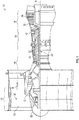
- the gas turbine engine includes a fan section 12, a compressor section 14, a combustor section 16, and a turbine section 18 disposed about a longitudinal axis A.
- the fan section 12 drives air along a bypass flow path B that may bypass the compressor section 14, the combustor section 16, and the turbine section 18.
- the compressor section 14 draws air in along a core flow path C where air is compressed by the compressor section 14 and is provided to or communicated to the combustor section 16.
- the compressed air is heated by the combustor section 16 to generate a high pressure exhaust gas stream that expands through the turbine section 18.
- the turbine section 18 extracts energy from the high pressure exhaust gas stream to drive the fan section 12 and the compressor section 14.
- the gas turbine engine 10 further includes a low-speed spool 20 and a high-speed spool 22 that are configured to rotate the fan section 12, the compressor section 14, and the turbine section 18 about the longitudinal axis A.
- the low-speed spool 20 may connect a fan 30 of the fan section 12 and a low-pressure compressor portion 32 of the compressor section 14 to a low-pressure turbine portion 34 of the turbine section 18.
- the turbine section 18 can include a rotating disc assembly 35.
- the high-speed spool 22 may connect a high pressure compressor portion 40 of the compressor section 14 and a high pressure turbine portion 42 of the turbine section 18.
- the fan 30 includes a fan rotor or fan hub 50 that carries a fan blade 52. The fan blade 52 radially extends from the fan hub 50.
- the rotating disc assembly 35 can be a turbine disc assembly to extract energy from the high pressure exhaust gas stream by rotation of a plurality of turbine discs.
- the turbine disc assembly can utilize retaining rings to retain turbine discs and cover plates within the gas turbine engine 10.
- the compressor portion 32 can include a similar rotating disc assembly 35 to compress airflow by rotation of a plurality of compressor discs.
- the compressor disc assembly can utilize retaining rings to retain compressor discs and cover plates within the gas turbine engine 10.
- the rotating disc assembly 35 can be any suitable assembly, including, but not limited to a turbine disc assembly or a compressor disc assembly.
- the rotating disc assembly 35 includes a rotating disc 102, a cover plate 104, and a retaining ring 110.
- the retaining ring 110 can prevent axial motion of the cover plate 104 relative to the rotating disc 102 to allow the rotating disc 102 and the cover plate 104 to be retained after assembly.
- the retaining ring 110 can be mounted against the lip of the rotating disc 102 to retain the cover plate 104 after assembly.
- multiple retaining rings 110 can be disposed on either side of the rotating disc 102 to prevent axial motion on either side of the rotating disc assembly 35.
- rotating disc 102 can be a disc segment and other parts that are not complete discs.
- the rotating disc assembly 35 is suitable for use with parts to be retained that are not rotating.
- the retaining ring 110 includes a rotating disc face 112, a cover plate face 114, and an end gap portion 120.
- the retaining ring 110 is a split ring that axially interfaces with the lip portion of the rotating disc 102 and the cover plate 104 via the rotating disc face 112 and the cover plate face 114 respectively.
- the retaining ring 110 can be formed from additive manufacturing processes, casting processes, machining processes or a combination thereof. Any other suitable process for manufacturing the retaining ring 110 is contemplated herein.
- the split ring construction of the retaining ring 110 allows for an end gap formed between the end gap portions 120.
- contact stresses of the cover plate 104 near the end gap defined by the end gap portions 120 can be reduced to improve life of the rotating disc assembly.
- the retaining ring 110 includes two tapered surfaces proximal to the end gap defined by the end gap portions 120.
- the cover plate face 114 includes a tapered surface in the end gap portion 120.
- the cover plate face 114 tapers away from the cover plate 104 to reduce stress concentrations experienced by the cover plate 104.
- the rotating disc face 112 includes a tapered surface in the end gap portion 120. In the illustrated embodiment, the rotating disc face 112 tapers away from the rotating disc 102 to reduce stress concentrations experienced by the cover plate 104.
- the retaining ring 110 includes an axially extending face 115.
- the axially extending face 115 extends inward from the cover plate face 114 to form a general "L" shape.
- the axially extending face 115 can provide radial support to the cover plate 104 and further aid in assembly by locating the cover plate 104 and the retaining ring 110 during assembly.
- the axially extending face 115 can aid in reducing stress on the retaining ring 110 and the cover plate 104.
- FIGS. 5A-7F various embodiments of retaining rings 110 with various stress reducing features are shown and described. Stress reducing features and geometries described herein can be combined to form a desired retaining ring to provide a desired level of stress distribution and stiffness. Features and geometries can be combined in any suitable combination and can be machined, internally formed, additively manufactured, etc. In the illustrated embodiments, the stress reducing features can be proximal to the end gap portions 120 of the retaining ring 110.
- FIGS. 5A-5C various embodiments of a retaining ring 110 are shown.
- FIGS. 5A-5C an end view of the end gap portion 120 of the retaining ring 110 is shown.
- a retaining ring 110 is shown without any stress reducing features present on the rotating disc face 112, the cover plate face 114, or the axially extending face 115.
- the use of a retaining ring 110 without any stress reducing features may cause high stress concentrations on the cover plate 104.
- FIG. 5B the retaining ring 110 is shown with stress reducing features 114a, 114b.
- stress reducing features 114a, 114b are radiused corners that are tangent to the cover plate face 114.
- the stress reducing feature 114b is also a radiused corner tangent to the axially extending face 115.
- the retaining ring 110 is shown with stress reducing features 114a, 114b.
- stress reducing features 114a, 114b are contoured contact surfaces formed on the cover plate face 114.
- the stress reducing feature 114a can be a contoured contact surface with the cover plate 104.
- FIGS. 6A-6F various embodiments of the retaining ring 110 are shown.
- a plan view of the end gap portion 120 of the retaining ring 110 is shown.
- the axially extending face 115 can extend any suitable distance both axially in radially.
- the axially extending face 115 can end before the end gap portion 120 or alternatively extend beyond the end gap portion 120.
- a retaining ring 110 is shown with stress reducing features 120a.
- the stress reducing feature 120a is a radiused corner that is tangent to the cover plate face 114 and the rotating disc face 112.
- the stress reducing feature 120a is disposed on the end gap portion 120 of the retaining ring 110.
- a retaining ring 110 is shown with stress reducing features 120a.
- the stress reducing feature 120a is a chamfered or contoured corner that transitions to the cover plate face 114 and the rotating disc face 112.
- FIG. 6C a retaining ring 110 is shown with stress reducing features 120a.
- the stress reducing feature 120a is an asymmetrical chamfered or contoured corner that transitions to the cover plate face 114 and the rotating disc face 112.
- a retaining ring 110 is shown with stress reducing features 114a and 120a.
- the stress reducing feature 114a is a scalloped surface within the cover plate face 114.
- the addition of scalloped surfaces on the retaining ring 110 can increase stiffness in desired areas, such as near the end gap portions 120.
- a retaining ring 110 is shown with stress reducing features 112a and 120a.
- the stress reducing feature 112a is a scalloped surface within the rotating disc face 112.
- a retaining ring 110 is shown with stress reducing features 112a, 114a, and 120a.
- the stress reducing feature 112a is a scalloped surface within the rotating disc face 112 and the stress reducing feature 114a is a scalloped surface within the cover plate face 114, wherein the stress reducing feature 114a is opposite to the stress reducing feature 112a.
- FIGS. 7A-7F various embodiments of the retaining ring 110 are shown.
- FIGS. 7A-7F an elevation view of the end gap portion 120 of the retaining ring 110 is shown.
- a retaining ring 110 is shown with stress reducing features 115a.
- the stress reducing feature 115a is a radiused corner that is tangent to the axially extending face 115. Further, the stress reducing feature 115a is disposed proximal to the end gap portion 120 of the retaining ring 110.
- FIG. 7B a retaining ring 110 is shown with stress reducing features 115a.
- the stress reducing feature 115a is a scarf cut that can optimize loading of the cover plate 104.
- a retaining ring 110 is shown with stress reducing features 115a and 115b.
- the stress reducing feature 115a is a radiused corner that is tangent to the axially extending face 115 and disposed in the end gap portion 120 of the retaining ring 110.
- the stress reducing feature 115b is a scarf cut that is disposed axially toward the cover plate face 114.
- FIG. 7D a retaining ring 110 is shown with stress reducing features 115a and 115b.
- the stress reducing feature 115a is a radiused corner that is tangent to the axially extending face 115. Further, the stress reducing feature 115b is a scalloped surface that can optimize stiffness of the retaining ring.
- a retaining ring 110 is shown with stress reducing features 115a and 115b.
- the stress reducing feature 115a is a contoured corner. Further, the stress reducing feature 115b is a scalloped surface that can optimize stiffness of the retaining ring.
- FIG. 7F a retaining ring 110 is shown with stress reducing features 115a and 115b.
- the stress reducing feature 115a is a radiused corner that is tangent to the axially extending face 115 and is disposed in the end gap portion 120 of the retaining ring 110. Further, the stress reducing feature 115b is a scalloped surface that can optimize stiffness of the retaining ring.
Abstract
Description
- The present disclosure relates to retaining rings for gas turbine engines, and more particularly to retaining rings with end gap features for gas turbine engines.
- Retaining rings for gas turbine engines can be utilized to retain a cover plate to a rotating disc within the engine. During operation, stress concentrations may form within the cover plate at the location of the retaining ring end gap that may cause contact stress and cracking.
- Accordingly, it is desirable to provide retaining rings with end gap features that can prevent stress concentrations within the cover plate.
- According to an embodiment, a retaining ring for use in a gas turbine engine includes a rotating disc face, a cover plate face, and an end gap portion defining an end gap, wherein at least one of the rotating disc face, the cover plate face, and the end gap portion includes a stress reducing feature.
- In addition to one or more of the features described above, or as an alternative, further embodiments could include an axially extending face extending from the cover plate face.
- In addition to one or more of the features described above, or as an alternative, further embodiments could include that the axially extending face includes the stress reducing feature.
- In addition to one or more of the features described above, or as an alternative, further embodiments could include that the stress reducing feature is a radius tangent to at least one of the rotating disc face, the cover plate face, and the end gap portion.
- In addition to one or more of the features described above, or as an alternative, further embodiments could include that the stress reducing feature is a contoured contact surface.
- In addition to one or more of the features described above, or as an alternative, further embodiments could include that the stress reducing feature is a scalloped surface.
- In addition to one or more of the features described above, or as an alternative, further embodiments could include that the stress reducing feature is a tapering surface.
- According to an embodiment, a rotating disc assembly for use with a gas turbine engine includes a rotating disc, a cover plate, and a retaining ring disposed between the rotating disc and the cover plate, wherein the retaining ring axially retains the rotating disc and the cover plate, the retaining ring including a rotating disc face to interface with the rotating disc, a cover plate face to interface with the cover plate, and an end gap portion defining an end gap, wherein at least one of the rotating disc face, the cover plate face, and the end gap portion includes a stress reducing feature.
- In addition to one or more of the features described above, or as an alternative, further embodiments could include an axially extending face extending from the cover plate face, wherein the axially extending face radially constrains the retaining ring against the cover plate.
- In addition to one or more of the features described above, or as an alternative, further embodiments could include that the axially extending face includes the stress reducing feature.
- In addition to one or more of the features described above, or as an alternative, further embodiments could include that the stress reducing feature is a radius tangent to at least one of the rotating disc face, the cover plate face, and the end gap portion.
- In addition to one or more of the features described above, or as an alternative, further embodiments could include that the stress reducing feature is a contoured contact surface.
- In addition to one or more of the features described above, or as an alternative, further embodiments could include that the stress reducing feature is a scalloped surface.
- In addition to one or more of the features described above, or as an alternative, further embodiments could include that the stress reducing feature is a tapering surface.
- According to an embodiment, a gas turbine engine includes a rotating disc assembly, including a rotating disc, a cover plate, and a retaining ring disposed between the rotating disc and the cover plate, wherein the retaining ring axially retains the rotating disc and the cover plate, the retaining ring including: a rotating disc face to interface with the rotating disc; a cover plate face to interface with the cover plate; and an end gap portion defining an end gap, wherein at least one of the rotating disc face, the cover plate face, and the end gap portion includes a stress reducing feature.
- In addition to one or more of the features described above, or as an alternative, further embodiments could include an axially extending face extending from the cover plate face, wherein the axially extending face radially constrains the retaining ring against the cover plate.
- In addition to one or more of the features described above, or as an alternative, further embodiments could include that the axially extending face includes the stress reducing feature.
- In addition to one or more of the features described above, or as an alternative, further embodiments could include that the stress reducing feature is a radius tangent to at least one of the rotating disc face, the cover plate face, and the end gap portion.
- In addition to one or more of the features described above, or as an alternative, further embodiments could include that the stress reducing feature is a contoured contact surface.
- In addition to one or more of the features described above, or as an alternative, further embodiments could include that the stress reducing feature is a scalloped surface.
- Other aspects, features, and techniques of the embodiments will become more apparent from the following description taken in conjunction with the drawings.
- The subject matter which is regarded as the present disclosure is particularly pointed out and distinctly claimed in the claims at the conclusion of the specification. The foregoing and other features, and advantages of the present disclosure are apparent from the following detailed description taken in conjunction with the accompanying drawings in which:
-
Fig. 1 is a schematic, partial cross-sectional view of a turbomachine in accordance with this disclosure; -
Fig. 2 is partial cross-sectional view of a rotating disc assembly for use with the turbomachine ofFig. 1 ; -
Fig. 3 is a partial plan view of the rotating disc assembly ofFig. 2 ; -
Fig. 4 is a partial cross-sectional view of another rotating disc assembly for use with the turbomachine ofFig. 1 ; -
Figs. 5A-5C are partial end views of various embodiments of retaining rings for use with the rotating disc assembly ofFig 4 ; -
Figs 6A-6F are partial plan views of various embodiments of retaining rings for use with the rotating disc assembly ofFig. 4 ; and -
Figs. 7A-7F are partial elevation views of various embodiments of retaining rings for use with the rotating disc assembly ofFig. 4 . - Embodiments provide a retaining ring with end gap features. The end gap features of the retaining ring can reduce contact stress on the cover plate during operation to prevent wear and improve life of the rotating disc assembly.
- Referring to
FIG. 1 a schematic representation of agas turbine engine 10 is shown. The gas turbine engine includes afan section 12, acompressor section 14, acombustor section 16, and aturbine section 18 disposed about a longitudinal axis A. Thefan section 12 drives air along a bypass flow path B that may bypass thecompressor section 14, thecombustor section 16, and theturbine section 18. Thecompressor section 14 draws air in along a core flow path C where air is compressed by thecompressor section 14 and is provided to or communicated to thecombustor section 16. The compressed air is heated by thecombustor section 16 to generate a high pressure exhaust gas stream that expands through theturbine section 18. Theturbine section 18 extracts energy from the high pressure exhaust gas stream to drive thefan section 12 and thecompressor section 14. - The
gas turbine engine 10 further includes a low-speed spool 20 and a high-speed spool 22 that are configured to rotate thefan section 12, thecompressor section 14, and theturbine section 18 about the longitudinal axis A. The low-speed spool 20 may connect afan 30 of thefan section 12 and a low-pressure compressor portion 32 of thecompressor section 14 to a low-pressure turbine portion 34 of theturbine section 18. In the illustrated embodiment, theturbine section 18 can include a rotatingdisc assembly 35. The high-speed spool 22 may connect a highpressure compressor portion 40 of thecompressor section 14 and a highpressure turbine portion 42 of theturbine section 18. Thefan 30 includes a fan rotor orfan hub 50 that carries afan blade 52. Thefan blade 52 radially extends from thefan hub 50. - In the illustrated embodiment, the rotating
disc assembly 35 can be a turbine disc assembly to extract energy from the high pressure exhaust gas stream by rotation of a plurality of turbine discs. The turbine disc assembly can utilize retaining rings to retain turbine discs and cover plates within thegas turbine engine 10. In certain embodiments, thecompressor portion 32 can include a similar rotatingdisc assembly 35 to compress airflow by rotation of a plurality of compressor discs. The compressor disc assembly can utilize retaining rings to retain compressor discs and cover plates within thegas turbine engine 10. - Referring to
FIG. 2 , a rotatingdisc assembly 35 is shown. The rotatingdisc assembly 35 can be any suitable assembly, including, but not limited to a turbine disc assembly or a compressor disc assembly. In the illustrated embodiment, therotating disc assembly 35 includes arotating disc 102, acover plate 104, and aretaining ring 110. Theretaining ring 110 can prevent axial motion of thecover plate 104 relative to the rotatingdisc 102 to allow therotating disc 102 and thecover plate 104 to be retained after assembly. Theretaining ring 110 can be mounted against the lip of the rotatingdisc 102 to retain thecover plate 104 after assembly. In the illustrate embodiment,multiple retaining rings 110 can be disposed on either side of the rotatingdisc 102 to prevent axial motion on either side of the rotatingdisc assembly 35. In certain embodiments, rotatingdisc 102 can be a disc segment and other parts that are not complete discs. In certain embodiments, therotating disc assembly 35 is suitable for use with parts to be retained that are not rotating. - Referring to
FIGS. 2 and 3 , the retainingring 110 includes arotating disc face 112, acover plate face 114, and anend gap portion 120. The retainingring 110 is a split ring that axially interfaces with the lip portion of therotating disc 102 and thecover plate 104 via therotating disc face 112 and thecover plate face 114 respectively. In certain embodiments, the retainingring 110 can be formed from additive manufacturing processes, casting processes, machining processes or a combination thereof. Any other suitable process for manufacturing theretaining ring 110 is contemplated herein. - The split ring construction of the retaining
ring 110 allows for an end gap formed between theend gap portions 120. Advantageously, with the use of the stress reducing geometries and features described herein, contact stresses of thecover plate 104 near the end gap defined by theend gap portions 120 can be reduced to improve life of the rotating disc assembly. - Referring to
FIG. 3 , the retainingring 110 includes two tapered surfaces proximal to the end gap defined by theend gap portions 120. In the illustrated embodiment, thecover plate face 114 includes a tapered surface in theend gap portion 120. In the illustrated embodiment, thecover plate face 114 tapers away from thecover plate 104 to reduce stress concentrations experienced by thecover plate 104. Similarly, in the illustrated embodiment, therotating disc face 112 includes a tapered surface in theend gap portion 120. In the illustrated embodiment, therotating disc face 112 tapers away from therotating disc 102 to reduce stress concentrations experienced by thecover plate 104. - Further referring to
FIG. 4 , in certain embodiments, the retainingring 110 includes anaxially extending face 115. In the illustrated embodiment, theaxially extending face 115 extends inward from thecover plate face 114 to form a general "L" shape. Theaxially extending face 115 can provide radial support to thecover plate 104 and further aid in assembly by locating thecover plate 104 and the retainingring 110 during assembly. In certain embodiments, theaxially extending face 115 can aid in reducing stress on the retainingring 110 and thecover plate 104. - Referring to
FIGS. 5A-7F , various embodiments of retainingrings 110 with various stress reducing features are shown and described. Stress reducing features and geometries described herein can be combined to form a desired retaining ring to provide a desired level of stress distribution and stiffness. Features and geometries can be combined in any suitable combination and can be machined, internally formed, additively manufactured, etc. In the illustrated embodiments, the stress reducing features can be proximal to theend gap portions 120 of the retainingring 110. - Referring to
FIGS. 5A-5C , various embodiments of a retainingring 110 are shown. InFIGS. 5A-5C , an end view of theend gap portion 120 of the retainingring 110 is shown. InFIG. 5A , a retainingring 110 is shown without any stress reducing features present on therotating disc face 112, thecover plate face 114, or theaxially extending face 115. In certain applications, the use of a retainingring 110 without any stress reducing features may cause high stress concentrations on thecover plate 104. InFIG. 5B , the retainingring 110 is shown withstress reducing features stress reducing features cover plate face 114. In the illustrated embodiment, thestress reducing feature 114b is also a radiused corner tangent to theaxially extending face 115. InFIG. 5C , the retainingring 110 is shown withstress reducing features stress reducing features cover plate face 114. In the illustrated embodiment, thestress reducing feature 114a can be a contoured contact surface with thecover plate 104. - Referring to
FIGS. 6A-6F , various embodiments of the retainingring 110 are shown. InFIGS. 6A-6F , a plan view of theend gap portion 120 of the retainingring 110 is shown. In the illustrated embodiments, theaxially extending face 115 can extend any suitable distance both axially in radially. In certain embodiments, theaxially extending face 115 can end before theend gap portion 120 or alternatively extend beyond theend gap portion 120. InFIG. 6A , a retainingring 110 is shown withstress reducing features 120a. In the illustrated embodiment, thestress reducing feature 120a is a radiused corner that is tangent to thecover plate face 114 and therotating disc face 112. Further, thestress reducing feature 120a is disposed on theend gap portion 120 of the retainingring 110. InFIG. 6B , a retainingring 110 is shown withstress reducing features 120a. In the illustrated embodiment, thestress reducing feature 120a is a chamfered or contoured corner that transitions to thecover plate face 114 and therotating disc face 112. InFIG. 6C , a retainingring 110 is shown withstress reducing features 120a. In the illustrated embodiment, thestress reducing feature 120a is an asymmetrical chamfered or contoured corner that transitions to thecover plate face 114 and therotating disc face 112. InFIG. 6D , a retainingring 110 is shown withstress reducing features stress reducing feature 114a is a scalloped surface within thecover plate face 114. Advantageously, the addition of scalloped surfaces on the retainingring 110 can increase stiffness in desired areas, such as near theend gap portions 120. InFIG. 6E , a retainingring 110 is shown withstress reducing features stress reducing feature 112a is a scalloped surface within therotating disc face 112. InFIG. 6F , a retainingring 110 is shown withstress reducing features stress reducing feature 112a is a scalloped surface within therotating disc face 112 and thestress reducing feature 114a is a scalloped surface within thecover plate face 114, wherein thestress reducing feature 114a is opposite to thestress reducing feature 112a. - Referring to
FIGS. 7A-7F , various embodiments of the retainingring 110 are shown. InFIGS. 7A-7F , an elevation view of theend gap portion 120 of the retainingring 110 is shown. InFIG. 7A , a retainingring 110 is shown withstress reducing features 115a. In the illustrated embodiment, thestress reducing feature 115a is a radiused corner that is tangent to theaxially extending face 115. Further, thestress reducing feature 115a is disposed proximal to theend gap portion 120 of the retainingring 110. InFIG. 7B , a retainingring 110 is shown withstress reducing features 115a. In the illustrated embodiment, thestress reducing feature 115a is a scarf cut that can optimize loading of thecover plate 104. InFIG. 7C , a retainingring 110 is shown withstress reducing features stress reducing feature 115a is a radiused corner that is tangent to theaxially extending face 115 and disposed in theend gap portion 120 of the retainingring 110. Further, thestress reducing feature 115b is a scarf cut that is disposed axially toward thecover plate face 114. InFIG. 7D , a retainingring 110 is shown withstress reducing features stress reducing feature 115a is a radiused corner that is tangent to theaxially extending face 115. Further, thestress reducing feature 115b is a scalloped surface that can optimize stiffness of the retaining ring. InFIG. 7E , a retainingring 110 is shown withstress reducing features stress reducing feature 115a is a contoured corner. Further, thestress reducing feature 115b is a scalloped surface that can optimize stiffness of the retaining ring. InFIG. 7F , a retainingring 110 is shown withstress reducing features stress reducing feature 115a is a radiused corner that is tangent to theaxially extending face 115 and is disposed in theend gap portion 120 of the retainingring 110. Further, thestress reducing feature 115b is a scalloped surface that can optimize stiffness of the retaining ring. - While the present disclosure has been described in detail in connection with only a limited number of embodiments, it should be readily understood that the present disclosure is not limited to such disclosed embodiments. Rather, the present disclosure can be modified to incorporate any number of variations, alterations, substitutions or equivalent arrangements not heretofore described, but which are commensurate with the scope of the present disclosure. Additionally, while various embodiments of the present disclosure have been described, it is to be understood that aspects of the present disclosure may include only some of the described embodiments. Accordingly, the present disclosure is not to be seen as limited by the foregoing description, but is only limited by the scope of the appended claims.
- The following clauses set out features of the present disclosure which may not presently be claimed in this application but which may form basis for future amendment of a divisional application.
- 1. A retaining ring for use in a gas turbine engine, the retaining ring comprising:
- a rotating disc face;
- a cover plate face; and
- an end gap portion defining an end gap, wherein at least one of the rotating disc face, the cover plate face, and the end gap portion includes a stress reducing feature.
- 2. The retaining ring of clause 1, further comprising an axially extending face extending from the cover plate face.
- 3. The retaining ring of clause 2, wherein the axially extending face includes the stress reducing feature.
- 4. The retaining ring of clause 1, wherein the stress reducing feature is a radius tangent to at least one of the rotating disc face, the cover plate face, and the end gap portion.
- 5. The retaining ring of clause 1, wherein the stress reducing feature is a contoured contact surface.
- 6. The retaining ring of clause 1, wherein the stress reducing feature is a scalloped surface.
- 7. The retaining ring of clause 1, wherein the stress reducing feature is a tapering surface.
- 8. A rotating disc assembly for use with a gas turbine engine, the rotating disc assembly comprising:
- a rotating disc;
- a cover plate; and
- a retaining ring disposed between the rotating disc and the cover plate, wherein the retaining ring axially retains the rotating disc and the cover plate, the retaining ring including:
- a rotating disc face to interface with the rotating disc;
- a cover plate face to interface with the cover plate; and
- an end gap portion defining an end gap, wherein at least one of the rotating disc face, the cover plate face, and the end gap portion includes a stress reducing feature.
- 9. The rotating disc assembly of clause 8, further comprising an axially extending face extending from the cover plate face, wherein the axially extending face radially constrains the retaining ring against the cover plate.
- 10. The rotating disc assembly of clause 9, wherein the axially extending face includes the stress reducing feature.
- 11. The rotating disc assembly of clause 8, wherein the stress reducing feature is a radius tangent to at least one of the rotating disc face, the cover plate face, and the end gap portion.
- 12. The rotating disc assembly of clause 8, wherein the stress reducing feature is a contoured contact surface.
- 13. The rotating disc assembly of clause 8, wherein the stress reducing feature is a scalloped surface.
- 14. The rotating disc assembly of clause 8, wherein the stress reducing feature is a tapering surface.
- 15. A gas turbine engine, comprising:
- a rotating disc assembly, including:
- a rotating disc;
- a cover plate; and
- a retaining ring disposed between the rotating disc and the cover plate, wherein the retaining ring axially retains the rotating disc and the cover plate, the retaining ring including:
- a rotating disc face to interface with the rotating disc;
- a cover plate face to interface with the cover plate; and
- an end gap portion defining an end gap, wherein at least one of the rotating disc face, the cover plate face, and the end gap portion includes a stress reducing feature.
- a rotating disc assembly, including:
- 16. The gas turbine engine of clause 15, further comprising an axially extending face extending from the cover plate face, wherein the axially extending face radially constrains the retaining ring against the cover plate.
- 17. The gas turbine engine of
clause 16, wherein the axially extending face includes the stress reducing feature. - 18. The gas turbine engine of clause 15, wherein the stress reducing feature is a radius tangent to at least one of the rotating disc face, the cover plate face, and the end gap portion.
- 19. The gas turbine engine of clause 15, wherein the stress reducing feature is a contoured contact surface.
- 20. The gas turbine engine of clause 15, wherein the stress reducing feature is a scalloped surface.
Claims (15)
- A retaining ring (110) for use in a gas turbine engine (10), the retaining ring comprising:a rotating disc face (112);a cover plate face (114); andan end gap portion (120) defining an end gap, wherein at least one of the rotating disc face, the cover plate face, and the end gap portion includes a stress reducing feature.
- The retaining ring (110) of claim 1, further comprising an axially extending face (115) extending from the cover plate face (114).
- The retaining ring (110) of claim 2, wherein the axially extending face (115) includes the stress reducing feature.
- The retaining ring (110) of claim 1, 2 or 3, wherein the stress reducing feature is a radius tangent to at least one of the rotating disc face (112), the cover plate face (114), and the end gap portion (120).
- The retaining ring (110) of any preceding claim, wherein the stress reducing feature is a contoured contact surface.
- The retaining ring (110) of any of claims 1 to 4, wherein the stress reducing feature is a scalloped surface.
- The retaining ring (110) of any of claims 1 to 4, wherein the stress reducing feature is a tapering surface.
- A rotating disc assembly (35) for use with a gas turbine engine (10), the rotating disc assembly comprising:a rotating disc (102);a cover plate (104); andthe retaining ring (110) of claim 1 disposed between the rotating disc and the cover plate, wherein the retaining ring axially retains the rotating disc and the cover plate, wherein the rotating disc face (112) interfaces with the rotating disc, and wherein the cover plate face (114) interfaces with the cover plate.
- The rotating disc assembly (35) of claim 8, further comprising an axially extending face (115) extending from the cover plate face (114), wherein the axially extending face radially constrains the retaining ring (110) against the cover plate (104).
- The rotating disc assembly (35) of claim 9, wherein the axially extending face (115) includes the stress reducing feature.
- The rotating disc assembly (35) of claim 8, 9 or 10, wherein the stress reducing feature is a radius tangent to at least one of the rotating disc face (112), the cover plate face (114), and the end gap portion (126).
- The rotating disc assembly (35) of any of claims 8 to 11, wherein the stress reducing feature is a contoured contact surface.
- The rotating disc assembly (35) of any of claims 8 to 11, wherein the stress reducing feature is a scalloped surface.
- The rotating disc assembly (35) of any of claims 8 to 11, wherein the stress reducing feature is a tapering surface.
- A gas turbine engine (10), comprising:the rotating disc assembly (35) of any of claims 8 to 13.
Applications Claiming Priority (1)
| Application Number | Priority Date | Filing Date | Title |
|---|---|---|---|
| US15/274,306 US10392966B2 (en) | 2016-09-23 | 2016-09-23 | Retaining ring end gap features |
Publications (2)
| Publication Number | Publication Date |
|---|---|
| EP3299580A1 true EP3299580A1 (en) | 2018-03-28 |
| EP3299580B1 EP3299580B1 (en) | 2020-12-02 |
Family
ID=59384021
Family Applications (1)
| Application Number | Title | Priority Date | Filing Date |
|---|---|---|---|
| EP17182485.7A Active EP3299580B1 (en) | 2016-09-23 | 2017-07-21 | Retaining ring end gap features |
Country Status (2)
| Country | Link |
|---|---|
| US (1) | US10392966B2 (en) |
| EP (1) | EP3299580B1 (en) |
Cited By (1)
| Publication number | Priority date | Publication date | Assignee | Title |
|---|---|---|---|---|
| EP3244014B1 (en) * | 2016-05-13 | 2021-01-20 | United Technologies Corporation | Retaining ring assembly for a gas turbine engine |
Families Citing this family (2)
| Publication number | Priority date | Publication date | Assignee | Title |
|---|---|---|---|---|
| US11391175B2 (en) * | 2019-06-13 | 2022-07-19 | The Regents Of The University Of Michigan | Vibration absorber dampers for integrally bladed rotors and other cyclic symmetric structures |
| US11313240B2 (en) | 2020-02-05 | 2022-04-26 | Raytheon Technologies Corporation | Rounded radial snap configuration for a gas turbine engine cover plate |
Citations (6)
| Publication number | Priority date | Publication date | Assignee | Title |
|---|---|---|---|---|
| US4304523A (en) * | 1980-06-23 | 1981-12-08 | General Electric Company | Means and method for securing a member to a structure |
| JPH10103007A (en) * | 1996-09-25 | 1998-04-21 | Ishikawajima Harima Heavy Ind Co Ltd | Slip off preventive plate of gas turbine moving blade |
| EP0921272A2 (en) * | 1997-12-03 | 1999-06-09 | Rolls-Royce Plc | Turbine rotor disc assembly |
| US20020018719A1 (en) * | 2000-08-10 | 2002-02-14 | Jean-Baptiste Arilla | Rotor blade retaining apparatus |
| EP1795709A2 (en) * | 2005-12-06 | 2007-06-13 | Rolls-Royce plc | Retention ring for gas turbine |
| US20070237645A1 (en) * | 2006-04-10 | 2007-10-11 | Snecma | Retaining device for axially retaining a rotor disk flange in a turbomachine |
Family Cites Families (2)
| Publication number | Priority date | Publication date | Assignee | Title |
|---|---|---|---|---|
| US4767276A (en) * | 1986-12-19 | 1988-08-30 | General Electric Company | Retainer ring |
| US5622475A (en) * | 1994-08-30 | 1997-04-22 | General Electric Company | Double rabbet rotor blade retention assembly |
-
2016
- 2016-09-23 US US15/274,306 patent/US10392966B2/en active Active
-
2017
- 2017-07-21 EP EP17182485.7A patent/EP3299580B1/en active Active
Patent Citations (6)
| Publication number | Priority date | Publication date | Assignee | Title |
|---|---|---|---|---|
| US4304523A (en) * | 1980-06-23 | 1981-12-08 | General Electric Company | Means and method for securing a member to a structure |
| JPH10103007A (en) * | 1996-09-25 | 1998-04-21 | Ishikawajima Harima Heavy Ind Co Ltd | Slip off preventive plate of gas turbine moving blade |
| EP0921272A2 (en) * | 1997-12-03 | 1999-06-09 | Rolls-Royce Plc | Turbine rotor disc assembly |
| US20020018719A1 (en) * | 2000-08-10 | 2002-02-14 | Jean-Baptiste Arilla | Rotor blade retaining apparatus |
| EP1795709A2 (en) * | 2005-12-06 | 2007-06-13 | Rolls-Royce plc | Retention ring for gas turbine |
| US20070237645A1 (en) * | 2006-04-10 | 2007-10-11 | Snecma | Retaining device for axially retaining a rotor disk flange in a turbomachine |
Cited By (1)
| Publication number | Priority date | Publication date | Assignee | Title |
|---|---|---|---|---|
| EP3244014B1 (en) * | 2016-05-13 | 2021-01-20 | United Technologies Corporation | Retaining ring assembly for a gas turbine engine |
Also Published As
| Publication number | Publication date |
|---|---|
| US20180087397A1 (en) | 2018-03-29 |
| US10392966B2 (en) | 2019-08-27 |
| EP3299580B1 (en) | 2020-12-02 |
Similar Documents
| Publication | Publication Date | Title |
|---|---|---|
| US8657570B2 (en) | Rotor blade with reduced rub loading | |
| US8662834B2 (en) | Method for reducing tip rub loading | |
| US8403645B2 (en) | Turbofan flow path trenches | |
| EP2080578B1 (en) | Linear friction welded blisk and method of fabrication | |
| US6471474B1 (en) | Method and apparatus for reducing rotor assembly circumferential rim stress | |
| US7887299B2 (en) | Rotary body for turbo machinery with mistuned blades | |
| JP5152492B2 (en) | Turbomachine casing with treatment, compressor and turbomachine including such casing | |
| EP2484867B1 (en) | Rotating component of a turbine engine | |
| US8167572B2 (en) | Dynamically tuned turbine blade growth pocket | |
| EP2971553B1 (en) | Rotor blade with a conic spline fillet at an intersection between a platform and a neck | |
| US10472729B2 (en) | Abrasive tip blade manufacture methods | |
| JP2016527426A (en) | Composite airfoil metal patch | |
| EP3299580A1 (en) | Retaining ring end gap features | |
| JP5628307B2 (en) | Rotor blade and method for reducing tip friction load | |
| EP3006676B1 (en) | Fan for a gas turbine engine, corresponding fan blade and manufacturing method | |
| WO2014096840A1 (en) | An aerofoil structure with tip portion cutting edges | |
| EP3594450A1 (en) | Blade for a gas turbine engine | |
| EP3284911A1 (en) | Fan case wear liner and gas turbine engine with such a wear liner | |
| GB2543327A (en) | Aerofoil tip profiles | |
| WO2015102676A1 (en) | Fan blade with root through holes |
Legal Events
| Date | Code | Title | Description |
|---|---|---|---|
| PUAI | Public reference made under article 153(3) epc to a published international application that has entered the european phase |
Free format text: ORIGINAL CODE: 0009012 |
|
| STAA | Information on the status of an ep patent application or granted ep patent |
Free format text: STATUS: THE APPLICATION HAS BEEN PUBLISHED |
|
| AK | Designated contracting states |
Kind code of ref document: A1 Designated state(s): AL AT BE BG CH CY CZ DE DK EE ES FI FR GB GR HR HU IE IS IT LI LT LU LV MC MK MT NL NO PL PT RO RS SE SI SK SM TR |
|
| AX | Request for extension of the european patent |
Extension state: BA ME |
|
| STAA | Information on the status of an ep patent application or granted ep patent |
Free format text: STATUS: REQUEST FOR EXAMINATION WAS MADE |
|
| 17P | Request for examination filed |
Effective date: 20180927 |
|
| RBV | Designated contracting states (corrected) |
Designated state(s): AL AT BE BG CH CY CZ DE DK EE ES FI FR GB GR HR HU IE IS IT LI LT LU LV MC MK MT NL NO PL PT RO RS SE SI SK SM TR |
|
| STAA | Information on the status of an ep patent application or granted ep patent |
Free format text: STATUS: EXAMINATION IS IN PROGRESS |
|
| 17Q | First examination report despatched |
Effective date: 20191024 |
|
| GRAP | Despatch of communication of intention to grant a patent |
Free format text: ORIGINAL CODE: EPIDOSNIGR1 |
|
| STAA | Information on the status of an ep patent application or granted ep patent |
Free format text: STATUS: GRANT OF PATENT IS INTENDED |
|
| INTG | Intention to grant announced |
Effective date: 20200617 |
|
| GRAS | Grant fee paid |
Free format text: ORIGINAL CODE: EPIDOSNIGR3 |
|
| GRAA | (expected) grant |
Free format text: ORIGINAL CODE: 0009210 |
|
| STAA | Information on the status of an ep patent application or granted ep patent |
Free format text: STATUS: THE PATENT HAS BEEN GRANTED |
|
| AK | Designated contracting states |
Kind code of ref document: B1 Designated state(s): AL AT BE BG CH CY CZ DE DK EE ES FI FR GB GR HR HU IE IS IT LI LT LU LV MC MK MT NL NO PL PT RO RS SE SI SK SM TR |
|
| REG | Reference to a national code |
Ref country code: GB Ref legal event code: FG4D |
|
| REG | Reference to a national code |
Ref country code: AT Ref legal event code: REF Ref document number: 1341153 Country of ref document: AT Kind code of ref document: T Effective date: 20201215 Ref country code: CH Ref legal event code: EP |
|
| REG | Reference to a national code |
Ref country code: IE Ref legal event code: FG4D |
|
| REG | Reference to a national code |
Ref country code: DE Ref legal event code: R096 Ref document number: 602017028650 Country of ref document: DE |
|
| RAP2 | Party data changed (patent owner data changed or rights of a patent transferred) |
Owner name: RAYTHEON TECHNOLOGIES CORPORATION |
|
| PG25 | Lapsed in a contracting state [announced via postgrant information from national office to epo] |
Ref country code: NO Free format text: LAPSE BECAUSE OF FAILURE TO SUBMIT A TRANSLATION OF THE DESCRIPTION OR TO PAY THE FEE WITHIN THE PRESCRIBED TIME-LIMIT Effective date: 20210302 Ref country code: RS Free format text: LAPSE BECAUSE OF FAILURE TO SUBMIT A TRANSLATION OF THE DESCRIPTION OR TO PAY THE FEE WITHIN THE PRESCRIBED TIME-LIMIT Effective date: 20201202 Ref country code: GR Free format text: LAPSE BECAUSE OF FAILURE TO SUBMIT A TRANSLATION OF THE DESCRIPTION OR TO PAY THE FEE WITHIN THE PRESCRIBED TIME-LIMIT Effective date: 20210303 Ref country code: FI Free format text: LAPSE BECAUSE OF FAILURE TO SUBMIT A TRANSLATION OF THE DESCRIPTION OR TO PAY THE FEE WITHIN THE PRESCRIBED TIME-LIMIT Effective date: 20201202 |
|
| REG | Reference to a national code |
Ref country code: NL Ref legal event code: MP Effective date: 20201202 |
|
| REG | Reference to a national code |
Ref country code: AT Ref legal event code: MK05 Ref document number: 1341153 Country of ref document: AT Kind code of ref document: T Effective date: 20201202 |
|
| PG25 | Lapsed in a contracting state [announced via postgrant information from national office to epo] |
Ref country code: SE Free format text: LAPSE BECAUSE OF FAILURE TO SUBMIT A TRANSLATION OF THE DESCRIPTION OR TO PAY THE FEE WITHIN THE PRESCRIBED TIME-LIMIT Effective date: 20201202 Ref country code: BG Free format text: LAPSE BECAUSE OF FAILURE TO SUBMIT A TRANSLATION OF THE DESCRIPTION OR TO PAY THE FEE WITHIN THE PRESCRIBED TIME-LIMIT Effective date: 20210302 Ref country code: PL Free format text: LAPSE BECAUSE OF FAILURE TO SUBMIT A TRANSLATION OF THE DESCRIPTION OR TO PAY THE FEE WITHIN THE PRESCRIBED TIME-LIMIT Effective date: 20201202 Ref country code: LV Free format text: LAPSE BECAUSE OF FAILURE TO SUBMIT A TRANSLATION OF THE DESCRIPTION OR TO PAY THE FEE WITHIN THE PRESCRIBED TIME-LIMIT Effective date: 20201202 |
|
| PG25 | Lapsed in a contracting state [announced via postgrant information from national office to epo] |
Ref country code: HR Free format text: LAPSE BECAUSE OF FAILURE TO SUBMIT A TRANSLATION OF THE DESCRIPTION OR TO PAY THE FEE WITHIN THE PRESCRIBED TIME-LIMIT Effective date: 20201202 Ref country code: NL Free format text: LAPSE BECAUSE OF FAILURE TO SUBMIT A TRANSLATION OF THE DESCRIPTION OR TO PAY THE FEE WITHIN THE PRESCRIBED TIME-LIMIT Effective date: 20201202 |
|
| REG | Reference to a national code |
Ref country code: LT Ref legal event code: MG9D |
|
| PG25 | Lapsed in a contracting state [announced via postgrant information from national office to epo] |
Ref country code: SM Free format text: LAPSE BECAUSE OF FAILURE TO SUBMIT A TRANSLATION OF THE DESCRIPTION OR TO PAY THE FEE WITHIN THE PRESCRIBED TIME-LIMIT Effective date: 20201202 Ref country code: LT Free format text: LAPSE BECAUSE OF FAILURE TO SUBMIT A TRANSLATION OF THE DESCRIPTION OR TO PAY THE FEE WITHIN THE PRESCRIBED TIME-LIMIT Effective date: 20201202 Ref country code: EE Free format text: LAPSE BECAUSE OF FAILURE TO SUBMIT A TRANSLATION OF THE DESCRIPTION OR TO PAY THE FEE WITHIN THE PRESCRIBED TIME-LIMIT Effective date: 20201202 Ref country code: CZ Free format text: LAPSE BECAUSE OF FAILURE TO SUBMIT A TRANSLATION OF THE DESCRIPTION OR TO PAY THE FEE WITHIN THE PRESCRIBED TIME-LIMIT Effective date: 20201202 Ref country code: RO Free format text: LAPSE BECAUSE OF FAILURE TO SUBMIT A TRANSLATION OF THE DESCRIPTION OR TO PAY THE FEE WITHIN THE PRESCRIBED TIME-LIMIT Effective date: 20201202 Ref country code: SK Free format text: LAPSE BECAUSE OF FAILURE TO SUBMIT A TRANSLATION OF THE DESCRIPTION OR TO PAY THE FEE WITHIN THE PRESCRIBED TIME-LIMIT Effective date: 20201202 Ref country code: PT Free format text: LAPSE BECAUSE OF FAILURE TO SUBMIT A TRANSLATION OF THE DESCRIPTION OR TO PAY THE FEE WITHIN THE PRESCRIBED TIME-LIMIT Effective date: 20210405 |
|
| PG25 | Lapsed in a contracting state [announced via postgrant information from national office to epo] |
Ref country code: AT Free format text: LAPSE BECAUSE OF FAILURE TO SUBMIT A TRANSLATION OF THE DESCRIPTION OR TO PAY THE FEE WITHIN THE PRESCRIBED TIME-LIMIT Effective date: 20201202 |
|
| REG | Reference to a national code |
Ref country code: DE Ref legal event code: R097 Ref document number: 602017028650 Country of ref document: DE |
|
| PG25 | Lapsed in a contracting state [announced via postgrant information from national office to epo] |
Ref country code: IS Free format text: LAPSE BECAUSE OF FAILURE TO SUBMIT A TRANSLATION OF THE DESCRIPTION OR TO PAY THE FEE WITHIN THE PRESCRIBED TIME-LIMIT Effective date: 20210402 |
|
| PLBE | No opposition filed within time limit |
Free format text: ORIGINAL CODE: 0009261 |
|
| STAA | Information on the status of an ep patent application or granted ep patent |
Free format text: STATUS: NO OPPOSITION FILED WITHIN TIME LIMIT |
|
| PG25 | Lapsed in a contracting state [announced via postgrant information from national office to epo] |
Ref country code: AL Free format text: LAPSE BECAUSE OF FAILURE TO SUBMIT A TRANSLATION OF THE DESCRIPTION OR TO PAY THE FEE WITHIN THE PRESCRIBED TIME-LIMIT Effective date: 20201202 Ref country code: IT Free format text: LAPSE BECAUSE OF FAILURE TO SUBMIT A TRANSLATION OF THE DESCRIPTION OR TO PAY THE FEE WITHIN THE PRESCRIBED TIME-LIMIT Effective date: 20201202 |
|
| 26N | No opposition filed |
Effective date: 20210903 |
|
| PG25 | Lapsed in a contracting state [announced via postgrant information from national office to epo] |
Ref country code: SI Free format text: LAPSE BECAUSE OF FAILURE TO SUBMIT A TRANSLATION OF THE DESCRIPTION OR TO PAY THE FEE WITHIN THE PRESCRIBED TIME-LIMIT Effective date: 20201202 Ref country code: DK Free format text: LAPSE BECAUSE OF FAILURE TO SUBMIT A TRANSLATION OF THE DESCRIPTION OR TO PAY THE FEE WITHIN THE PRESCRIBED TIME-LIMIT Effective date: 20201202 |
|
| PG25 | Lapsed in a contracting state [announced via postgrant information from national office to epo] |
Ref country code: ES Free format text: LAPSE BECAUSE OF FAILURE TO SUBMIT A TRANSLATION OF THE DESCRIPTION OR TO PAY THE FEE WITHIN THE PRESCRIBED TIME-LIMIT Effective date: 20201202 |
|
| REG | Reference to a national code |
Ref country code: CH Ref legal event code: PL |
|
| PG25 | Lapsed in a contracting state [announced via postgrant information from national office to epo] |
Ref country code: MC Free format text: LAPSE BECAUSE OF FAILURE TO SUBMIT A TRANSLATION OF THE DESCRIPTION OR TO PAY THE FEE WITHIN THE PRESCRIBED TIME-LIMIT Effective date: 20201202 |
|
| REG | Reference to a national code |
Ref country code: BE Ref legal event code: MM Effective date: 20210731 |
|
| PG25 | Lapsed in a contracting state [announced via postgrant information from national office to epo] |
Ref country code: LI Free format text: LAPSE BECAUSE OF NON-PAYMENT OF DUE FEES Effective date: 20210731 Ref country code: CH Free format text: LAPSE BECAUSE OF NON-PAYMENT OF DUE FEES Effective date: 20210731 |
|
| PG25 | Lapsed in a contracting state [announced via postgrant information from national office to epo] |
Ref country code: IS Free format text: LAPSE BECAUSE OF FAILURE TO SUBMIT A TRANSLATION OF THE DESCRIPTION OR TO PAY THE FEE WITHIN THE PRESCRIBED TIME-LIMIT Effective date: 20210402 Ref country code: LU Free format text: LAPSE BECAUSE OF NON-PAYMENT OF DUE FEES Effective date: 20210721 |
|
| PG25 | Lapsed in a contracting state [announced via postgrant information from national office to epo] |
Ref country code: IE Free format text: LAPSE BECAUSE OF NON-PAYMENT OF DUE FEES Effective date: 20210721 Ref country code: BE Free format text: LAPSE BECAUSE OF NON-PAYMENT OF DUE FEES Effective date: 20210731 |
|
| PG25 | Lapsed in a contracting state [announced via postgrant information from national office to epo] |
Ref country code: HU Free format text: LAPSE BECAUSE OF FAILURE TO SUBMIT A TRANSLATION OF THE DESCRIPTION OR TO PAY THE FEE WITHIN THE PRESCRIBED TIME-LIMIT; INVALID AB INITIO Effective date: 20170721 |
|
| P01 | Opt-out of the competence of the unified patent court (upc) registered |
Effective date: 20230520 |
|
| PG25 | Lapsed in a contracting state [announced via postgrant information from national office to epo] |
Ref country code: CY Free format text: LAPSE BECAUSE OF FAILURE TO SUBMIT A TRANSLATION OF THE DESCRIPTION OR TO PAY THE FEE WITHIN THE PRESCRIBED TIME-LIMIT Effective date: 20201202 |
|
| PGFP | Annual fee paid to national office [announced via postgrant information from national office to epo] |
Ref country code: FR Payment date: 20230621 Year of fee payment: 7 |
|
| PGFP | Annual fee paid to national office [announced via postgrant information from national office to epo] |
Ref country code: GB Payment date: 20230620 Year of fee payment: 7 |
|
| PGFP | Annual fee paid to national office [announced via postgrant information from national office to epo] |
Ref country code: DE Payment date: 20230620 Year of fee payment: 7 |