EP3299513A1 - Clothes dryer - Google Patents
Clothes dryer Download PDFInfo
- Publication number
- EP3299513A1 EP3299513A1 EP15892649.3A EP15892649A EP3299513A1 EP 3299513 A1 EP3299513 A1 EP 3299513A1 EP 15892649 A EP15892649 A EP 15892649A EP 3299513 A1 EP3299513 A1 EP 3299513A1
- Authority
- EP
- European Patent Office
- Prior art keywords
- condensed water
- communication path
- air flow
- flow path
- water storage
- Prior art date
- Legal status (The legal status is an assumption and is not a legal conclusion. Google has not performed a legal analysis and makes no representation as to the accuracy of the status listed.)
- Granted
Links
Images


Classifications
-
- D—TEXTILES; PAPER
- D06—TREATMENT OF TEXTILES OR THE LIKE; LAUNDERING; FLEXIBLE MATERIALS NOT OTHERWISE PROVIDED FOR
- D06F—LAUNDERING, DRYING, IRONING, PRESSING OR FOLDING TEXTILE ARTICLES
- D06F58/00—Domestic laundry dryers
- D06F58/20—General details of domestic laundry dryers
- D06F58/24—Condensing arrangements
-
- D—TEXTILES; PAPER
- D06—TREATMENT OF TEXTILES OR THE LIKE; LAUNDERING; FLEXIBLE MATERIALS NOT OTHERWISE PROVIDED FOR
- D06F—LAUNDERING, DRYING, IRONING, PRESSING OR FOLDING TEXTILE ARTICLES
- D06F58/00—Domestic laundry dryers
- D06F58/20—General details of domestic laundry dryers
-
- D—TEXTILES; PAPER
- D06—TREATMENT OF TEXTILES OR THE LIKE; LAUNDERING; FLEXIBLE MATERIALS NOT OTHERWISE PROVIDED FOR
- D06F—LAUNDERING, DRYING, IRONING, PRESSING OR FOLDING TEXTILE ARTICLES
- D06F58/00—Domestic laundry dryers
- D06F58/02—Domestic laundry dryers having dryer drums rotating about a horizontal axis
-
- D—TEXTILES; PAPER
- D06—TREATMENT OF TEXTILES OR THE LIKE; LAUNDERING; FLEXIBLE MATERIALS NOT OTHERWISE PROVIDED FOR
- D06F—LAUNDERING, DRYING, IRONING, PRESSING OR FOLDING TEXTILE ARTICLES
- D06F58/00—Domestic laundry dryers
- D06F58/20—General details of domestic laundry dryers
- D06F58/206—Heat pump arrangements
-
- D—TEXTILES; PAPER
- D06—TREATMENT OF TEXTILES OR THE LIKE; LAUNDERING; FLEXIBLE MATERIALS NOT OTHERWISE PROVIDED FOR
- D06F—LAUNDERING, DRYING, IRONING, PRESSING OR FOLDING TEXTILE ARTICLES
- D06F58/00—Domestic laundry dryers
- D06F58/20—General details of domestic laundry dryers
- D06F58/22—Lint collecting arrangements
Definitions
- Embodiments disclosed herein relate to a clothes dryer capable of drying clothes.
- a circulation-type clothes dryer circulating dehumidified and heated air has been widely used.
- a fan device for circulating air for drying, a cooling device for cooling and dehumidifying the air for drying, and a heating device for heating the air passing through the cooling device were all disposed in the circulation air flow path.
- condensed water formed by dehumidification is attached to the surface of the cooling device in the form of droplets.
- a technique has been widely used wherein the technique is configured such that a condensed water container (drain pan) for collecting the condensed water is disposed and the condensed water recovered to the condensed water container is discharged to the outside or is stored in a separate water storage tank.
- Patent document 1 discloses a technique of collecting condensed water dehumidified by a cooling device, in a drain pan and discharging the collected condensed water to the outside of a washing and drying machine by a pump.
- the drain pan is divided into a portion (hereinafter referred to as a condensed water storage chamber) communicated with an air flow path (hereinafter referred to as a first air flow path) in the side of the upstream of the fan device via a drain hole (opening), and a portion in which a pump is placed (hereinafter referred to as a pump chamber), wherein the condensed water storage chamber and the pump chamber are communicated with each other via a bottom portion thereof.
- a condensed water storage chamber communicated with an air flow path (hereinafter referred to as a first air flow path) in the side of the upstream of the fan device via a drain hole (opening), and a portion in which a pump is placed (hereinafter referred to as a pump chamber), wherein the
- condensed water (dehumidified water) condensed in a cooling device is recovered to a dehumidifying tank through a recovery flow path provided in the lower part of the cooling device, and the recovered condensed water is transferred to the water storage tank disposed above a body (a body of the clothes dryer) by a pump (water supply pump).
- a wall portion configured to divide the pump chamber is provided with a removable covering portion for each pump section to improve the maintainability when using a pump chamber, as illustrated in patent document 1 (Japanese Patent Application Laid-Open No. 2011-239817 ).
- the pump chamber configured as described above may not be constructed in a completely sealed structure, and thus a part of the pump chamber is exposed to the atmosphere. Accordingly, when the washing and drying machine using such a pump chamber starts to operate, the air pressure in both the pump chamber and the condensed water storage chamber becomes negative. However, the air pressure in the pump chamber is higher than the air pressure in the condensed water storage chamber since the pump chamber is communicated with the first air flow path through the condensed water storage chamber, and the atmosphere flows to the pump chamber, and thus the condensed water level stored in the pump chamber may become lower than the condensed water level stored in the condensed water storage chamber.
- the communication path connecting the condensed water storage chamber to the pump chamber is submerged and blocked. Accordingly, the atmosphere flows to the pump chamber but the airflow between the pump chamber and the first air flow path is obstructed, thereby further increasing the differential pressure and the water level difference.
- the pump chamber is exposed to the atmosphere through the water storage tank or the hose when the pump chamber is communicated with the additional water storage tank via the hose. Accordingly, the atmosphere flows into the pump chamber.
- the length of the communication path connecting the condensed water storage chamber and the pump chamber is widened in the height direction so that the communication path is not submerged even if the condensed water increases.
- the airflow between the pump chamber and the circulation air flow path is maintained, so that an increase in the differential pressure can be suppressed.
- the air flows from the pump chamber side to the condensed water storage chamber side through the widely secured communication path, thereby causing a wave on the received condensed water surface, which causes scattering of the condensed water.
- Such a problem is not limited to a configuration in which the pump chamber is closed by the removable covering portion or a configuration in which the pump chamber is communicated with the water storage tank, and is related to the entirety of a dryer having a pump chamber in which at least a part thereof is communicated with the atmosphere.
- a clothes dryer including a body, a drum provided inside of the body, a fan device configured to circulate air for drying supplied to the drum, a circulation air flow path communicated with the drum and in which the air for drying is circulated by the fan device, a cooling device configured to dehumidify the air for drying by cooling the air for drying in the circulation air flow path, a condensed water storage chamber communicated with the circulation air flow path and configured to store condensed water generated by the cooling device, a pump chamber communicated with an outside space of the circulation air flow path and configured to accommodate a pump pumping the condensed water, a first communication path configured to flow the condensed water stored in the condensed water storage chamber to the pump chamber by allowing the condensed water storage chamber to be communicated with the pump chamber and a second communication path configured to allow the circulation air flow path to be communicated with at least one of the pump chamber and the outside space of the circulation air flow path.
- the circulation air flow path comprises a first air flow path communicated with the condensed water storage chamber to allow the air for drying passed through the drum to flow to the fan device, and a second air flow path provided to allow the air for drying passed through the fan device to flow to the drum, again.
- One end of the second communication path is opened in the pump chamber and other end of the second communication path is opened in the first air flow path.
- a drain portion configured to allow the condensed water storage chamber to be communicated with the first air flow path, and the second communication path is closer to the fan device than the drain portion.
- One end of the second communication path is opened in the pump chamber and other end of the second communication path is opened in the condensed water storage chamber so that the pump chamber is communicated with the first air flow path through the condensed water storage chamber.
- the second communication path is provided in a position higher than a position in which the first communication path is opened in the condensed water storage chamber.
- a portion of the second communication path penetrates the first communication path.
- the second communication path is formed in a tubular shape, and the second communication path comprises a curved portion so that the curved portion penetrates the first communication path.
- a partition member is provided in the first communication path to partition the first communication path, and thus the second communication path is provided between the first communication path by the partition member.
- One end of the second communication path is opened in the first air flow path and other end of the second communication path is opened in a rear side of the body.
- the second communication path is closer to the fan device than the drain portion configured to allow the condensed water storage chamber to be communicated with the first air flow path.
- One end of the second communication path is opened in the condensed water storage chamber and the other end of the second communication path is opened to the outside space of the body so that the first air flow path is communicated with the outside space of the body through the condensed water storage chamber.
- the pump chamber comprises an opening opened to the atmosphere, and a covering portion removably provided to close the opening of the pump chamber.
- a clothes dryer including a drum, a circulation air flow path communicated with the drum and configured to allow air for drying to be circulated, the circulation air flow path provided with a first air flow path configured to allow the air for drying passed through the drum to be cooled and dehumidified, and a second air flow path configured to allow the dehumidified air for drying to flow to the drum, again, a condensed water storage chamber communicated with the first air flow path and configured to store condensed water generated by a cooling device, a pump chamber provided with an inlet port configured to allow condensed water stored in the condensed water storage chamber to be introduced and a pump configured to pump condensed water, the pump chamber communicated with the outside space of the circulation air flow path, and at least one communication path configured to introduce air to at least one of the first air flow path and the pump chamber to reduce the pressure difference between the condensed water storage chamber and the pump chamber.
- one end of the at least one communication path is opened in the pump chamber and other end of the at least one communication path is opened in at least one of the inside of the first air flow path and the condensed water storage chamber.
- one end of the at least one communication path is opened in the first air flow path and other end of the at least one communication path is communicated with at least one of the inside of the pump chamber and the outside of the circulation air flow path.
- one end of the at least one communication path is opened in the condensed water storage chamber to be communicated with the first air flow path and the other end of the at least one communication path is communicated with the outside of the circulation air flow path.
- the proposed clothes dryer it is possible to reliably prevent the backflow and the scattering of the condensed water, which is generated by the dehumidification, and it is possible to allow a fan device to have an increased air flow rate.
- a clothes dryer D as a dryer is provided with a body 1 having a vertically elongated rectangular parallelepiped shape extending along the vertical direction.
- a clothes inlet 2 is opened in the upper part of the front surface of the body 1, wherein the clothes inlet 2 is formed in a circular shape when viewing from the front side, and is opened or closed by a pivotable covering portion 3.
- a drum 4 corresponding to an object accommodating portion is communicated with the clothes inlet 2 to accommodate clothes C that is an object of drying, and the drum 4 is rotatably supported in the upper portion of the inside of the body 1.
- the covering portion 3 is opened, the drum 4 may accommodate the clothes C put through the clothes inlet 2.
- the drum 4 is formed in cylindrical shape having a bottom having a rotary shaft center in the horizontal front and back direction. In a state in which an opening of the drum 4 is toward the clothes inlet 2, the center of the bottom portion of the drum 4 may be supported against a side wall portion of an intake side duct 7 to be rotatable via a shaft 30, and the drum 4 may be rotated with respect to the rotary shaft center.
- a circulation discharge port 31 discharging air used for drying the clothes C, and a circulation intake port 32 sucking the air used for drying the clothes C are communicated with the drum 4.
- the shaft 30 is connected to a drum rotation motor (not shown) disposed in the body 1 and is driven by the drum rotation motor when the clothes dryer D is operated to rotate the drum 4 at a predetermined speed. It is possible to directly rotate the drum 4 via a belt (not shown) by the rotation motor.
- a discharge side duct 5 whose one end is communicated with the circulation discharge port 31 and the intake side duct 7 whose one end is communicated with the circulation intake port 32, and a heat drying duct 6 connecting the other end of the discharge side duct 5 to the other end of the intake side duct 7 are installed.
- An endless circulation air flow path 8 circulating the air for drying by passing through the drum 4 is formed by a space in the ducts 5, 6, and 7.
- a lint filter 29 may be installed between the ducts 5 and 6 to collect lint generated from the clothes C, and as needed, the lint may be discharged to the outside of the body 1.
- the discharge side duct 5 is extended in the vertical direction on the front side in the body 1.
- the upper end portion of the discharge side duct 5 is connected to the circulation discharge port 31 in a sealed manner.
- the heat drying duct 6 is extended in the front and back direction on the bottom side (the lower side of the drum 4) in the body 1 and an end portion of the front side is connected to the lower end portion of the discharge side duct 5 in a sealed manner.
- the intake side duct 7 is extended in the vertical direction on the rear side in the body 1 and the lower end portion of the intake side duct 7 is connected to the rear end portion of the heat drying duct 6 in a sealed manner.
- the end portion of the intake side duct 7 is connected to the circulation intake port 32 in a sealed manner.
- the drum 4 is connected to the circulation discharge port 31 and the circulation intake port 32 in a sealed manner or a freely rotatable manner.
- a fan device 10 is installed in a connecting portion between the heat drying duct 6 and the intake side duct 7, which is the circulation air flow path 8 extending in the front and back direction in the lower portion of the clothes dryer D is curved toward the upper portion.
- the fan device 10 is provided with a casing 10b and a cylindrical impeller 10a rotatably supported in the casing 10b to have a plurality of blades on a side surface thereof.
- the casing 10b is provided with an intake port 10c that opens in a direction parallel to the rotation axis of the impeller 10a and a discharge port 10d that opens in a direction perpendicular to the rotation axis.
- the intake port 10c and the discharge port 10d are connected to the rear end of the heat drying duct 6 and the lower end of the intake side duct 7, respectively.
- a centrifugal fan device having a multi-blade fan may be applied to the fan device 10.
- the circulation air flow path 8 is provided with an evaporator 9a composed of a heat exchanger as a cooling device for cooling and dehumidifying air, a condenser 9b as a heater heating the air passed through the cooling device.
- the evaporator 9a and the condenser 9b are installed and supported on a cover base 6a corresponding to a supporting plate, in the heat drying duct 6.
- the evaporator 9a is installed in the upstream side (front side) of the circulation air flow path 8 and the condenser 9b is installed in the downstream (rear side) of the evaporator 9a to be apart from the evaporator 9a by a predetermined distance.
- the circulation air flow path 8 is provided with a first air flow path 8a in which the air for drying passing through the drum 4 flows to the fan device 10 by passing through the evaporator 9a and the condenser 9b in order, and a second air flow path 8b separated from the first air flow path 8a, and in which the air for drying passing through the fan device 10 flows to the drum 4.
- the first air flow path 8a is formed by the discharge side duct 5 and the heat drying duct 6
- the second air flow path 8b is formed by the intake side duct 7.
- the first air flow path 8a becomes the negative pressure while the second air flow path 8b becomes the positive pressure.
- the size of the negative pressure and the positive pressure that is the magnitude of the differential pressure between the atmospheric pressure and the air pressure in the first air flow path 8a or the second air flow path 8b, increases from the drum 4 toward the fan device 10, respectively.
- a compressor 9c and a decompressor 9d are provided in the body 1, the evaporator 9a, the compressor 9c, and the condenser 9b, and the decompressor 9d are connected in order via a refrigeration pipe 9e so that a heat pump cycle 9 is formed.
- the evaporator 9a and the condenser 9b exchange heat between the air flowing into the heat drying duct 6.
- gas refrigerant which is discharged from the compressor 9c and at a high temperature and a high pressure, becomes liquid refrigerant at a low temperature and a low pressure after being condensed in the condenser 9b and expanded in the decompressor 9d.
- the liquid refrigerant is evaporated in the evaporator 9a and then returns to the compressor 9c.
- the air is cooled and dehumidified by the evaporation heat generated when the refrigerant passes through the evaporator 9a, while the air is heated by the condensation heat generated when the refrigerant passes through the condenser 9b.
- a condensed water storage chamber 11 collecting and storing the condensed water W generated in the evaporator 9a is provided below the heat drying duct 6.
- the condensed water storage chamber 11 is opened upward and an opening thereof is closed by the cover base 6a.
- the heat drying duct 6 and the condensed water storage chamber 11 is partitioned by the cover base 6a.
- a drain hole 6b is formed in the cover base 6a as a drain portion corresponding to a communication path penetrating in the vertical direction directly below the evaporator 9a.
- the condensed water W which is generated when the air for drying in the first air flow path 8a is dehumidified by the evaporator 9a, is discharged to the condensed water storage chamber 11 through the drain hole 6b.
- the cover base 6a is inclined toward the lower side as it approaches the drain hole 6b from the lower side of the evaporator 9a (see FIGS. 2 and 6 ), and the cover base 6a guides the condensed water W dropped around the drain hole 6b to the drain hole 6b.
- the condensed water storage chamber 11 is communicated with the first air flow path 8a by the drain hole 6b and collects the condensed water W through the drain hole 6b.
- a bottom surface 11 a of the condensed water storage chamber 11 is inclined downward from the front side toward the rear side, so that the collected condensed water W flows backward.
- the width of the condensed water storage chamber 11 in the left-right direction is narrowed as being near the rear side, as shown in FIG. 6 , so that the condensed water W more stably flows as being near the rear side.
- the clothes dryer (D) includes a pump chamber 16 containing a pump 19 pumping the condensed water W collected in the condensed water storage chamber 11.
- the pump chamber 16 is mounted on the rear lower portion of the body 1 and communicated with the condensed water storage chamber 11 through a first communication path 12 (i.e., an inlet, hereinafter referred to as a first communication path).
- the first communication path 12 penetrating the lower portion of the rear wall portion 11 b is formed and a rear end portion of the condensed water storage chamber 11 and a front end portion of the pump chamber 16 is integrally connected to each other by the first communication path 12.
- the first communication path 12 is formed as a through-hole extending substantially in the front and back direction and the first communication path 12 is configured to allow the condensed water storage chamber 11 to be communicated with the pump chamber 16 through the bottom portions thereof.
- the condensed water W flowing from the condensed water storage chamber 11 is guided to the pump chamber 16 by the first communication path 12. As shown in FIGS. 2 and 6 , the height at which the first communication path 12 is opened in the condensed water storage chamber 11 is lower than the lower end of the drain hole 6b.
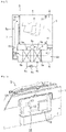
- the pump chamber 16 is opened toward the upper side and defines a space in the form of a horizontally long rectangular parallelepiped which is communicated with the space outside of the body 1 through the opening 15 as shown in FIGS. 4 A and 6.
- the pump chamber 16 is equipped with a removable covering portion 18 configured to close the opening 15 in a substantially sealed manner.
- the covering portion 18 is formed to be fittable around the opening 15 of the pump chamber 16 and the covering portion 18 is mounted to the opening 15 by being coupled to the opening 15.
- a material (not shown) formed of a soft material having a viability such as natural rubber and soft resin is mounted and thus when the covering portion 18 is fitted into the opening 15, the opening 15 is closed in a substantially sealed manner.
- the pump 19 pumping the condensed water W accommodated in the pump chamber 16 is mounted on the right portion of the covering portion 18, and a water level sensor 21 corresponding to a water level detector detecting the water level of the water in the pump chamber 16 is mounted on the left portion of the covering portion 18.
- a hose connecting hole 23 is formed at a substantially central portion on the front portion of the covering portion 18 in the left-right direction.
- a leak-proof hose 24 is inserted in the hose connecting hole 23 in the liquid-tight state (not shown in FIGS. 4B and 6 ).
- the pump 19, the water level sensor 21 and the leak-proof hose 24 may be individually detachable from the covering portion 18, respectively.
- the pump 19 is a water lift type submersible pump and has a pump casing 19a provided with an absorption port and a discharge port (both not shown).
- the pump 19 is fixed to the covering portion 18 such that the absorption port is located near the bottom of the pump chamber 16 while the discharge port is located above the covering portion 18.
- the condensed water W stored in the pump chamber 16 is pumped by the operation of the pump 19.
- a water lift hose 20 (e. g, a synthetic resin product) corresponding to a connecting waterway is connected to the discharge port of the pump 19. As illustrated in FIG. 1 , the other end of the water lift hose 20 is connected to the additional water storage tank 25 and then delivers the condensed water W pumped from the pump chamber 16 to the water storage tank 25.
- the water storage tank 25 is disposed above the drum 4 in the body 1 and thus as needed, the water storage tank 25 may be pulled out from the body 1.
- the water storage tank 25 is installed in a condensed water storage chamber for a storage water tank 26 formed in the accommodation container shape, and the condensed water W overflowing from the water storage tank 25 is stored in the condensed water storage chamber for the water storage tank 26.
- the leak-proof hose 24 is connected to the bottom of the condensed water storage chamber for the water storage tank 26, as illustrated in FIGS. 1 and 2 , and the condensed water W overflowing from the water storage tank 25 is returned to the pump chamber 16 via the leak-proof hose 24.
- the pump chamber 16 and a space A except for the circulation air flow path are communicated with each other through the condensed water storage chamber for the water storage tank 26 and the leak-proof hose 24.
- FIG. 1 illustrates the water lift hose 20 and the leak-proof hose 24 are disposed in the rear side of the intake side duct 7, but the water lift hose 20 and the leak-proof hose 24 may be disposed in the left side or the right side of the intake side duct 7.
- the water level sensor 21 has a tubular stem 21 b hanged on the pump chamber 16 from the covering portion 18 and a float 21 a supported by the stem 21 b to be vertically movable within a predetermined range with respect to the stem 21 b.
- the water level sensor 21 senses the water level by the height of the float 21 a.
- the clothes dryer D includes a controller (not shown). The controller operates the pump 19 when the water level sensed by the water level sensor 21 exceeds a predetermined threshold level L .
- a second communication path 17 is installed in the lower end portion of the rear wall portion 6h of the heat drying duct 6 to which the rear end of the cover base 6a is connected, wherein the second communication path 17 is a through hole type elongating in the left and right direction and extending in the front and back direction.
- the rear end of the second communication path 17 is opened in the pump chamber 16 while the front end of the second communication path 17 is opened in the first air flow path 8a.
- the second communication path 17 allows the first air flow path 8a to be communicated with the pump chamber 16 to reduce the differential pressure between the condensed water storage chamber 11 and the pump chamber 16.
- the second communication path 17 (i.e., a communication path, hereinafter referred to as a second communication path) is opened in the pump chamber 16 in a position higher than a position in which the first communication path 12 is opened in the pump chamber 16, as illustrated in FIGS. 2 and 6 .
- the second communication path 17 is configured such that a height in which the second communication path 17 is opened in the pump chamber 16 and a height in which the second communication path 17 is opened in the condensed water storage chamber 11 are higher than the threshold level L in which the pump 19 starts to operate.
- the second communication path 17 is opened into the first air flow path 8a in the direct downstream than the drain hole 6b.
- the drum rotation motor, the fan device 10 and the heat pump cycle 9 operate.
- a pressure difference occurs such that in the circulation air flow path 8, the first air flow path 8a becomes the negative pressure and the second air path 8b becomes the positive pressure by the operation of the fan device 10.
- the air pressure on the direct upstream side of the fan device 10 may be lower than the atmospheric pressure by 300 Pa or more.
- the air in the drum 4 circulates in the circulation air flow path 8 as the air for drying in accordance with the differential pressure.
- the air for drying in the drum 4 flows into the discharge side duct 5 through the circulation discharge port 31, and then flows toward the lower portion in the front side of the body 1 and then flows into the heat drying duct 6.
- the air introduced into the heat drying duct 6 flows the lower side of the body 1 toward the rear side along the heat drying duct 6.
- the evaporator 9a and the condenser 9b constituting the heat pump cycle 9 are disposed in order in the downstream of the heat drying duct 6. Therefore, as the air for drying passes through the heat drying duct 6, the air for drying is cooled and dehumidified in the evaporator 9a, and then heated in the condenser 9b so as to be adjusted to a state suitable for drying the clothes C.
- the air for drying that is passed through the heat drying duct 6 is passed through inside of the fan device 10 and delivered, and introduced into the intake side duct 7 as illustrated by the arrows A2 and A3 of FIG. 1 .
- the air for drying flowing into the intake side duct 7 flows to the upper portion in the rear side of the body 1 along the intake side duct 7 and then flows into the drum 4 through the circulation intake port 32.
- the air for drying is maintained at a predetermined humidity and temperature while the clothes dryer D operates, thereby drying the clothes C in the drum 4. Since the drum 4 is rotated at a predetermined speed by driving the drum rotation motor (not shown) during the operation of the clothes dryer D, the clothes C in the drum 4 are agitated, so that the air for drying is uniformly supplied to the clothes C in the drum 4.
- the condensed water W in the form of water droplets which is generated by the dehumidification, is attached to the surface of the evaporator 9a.
- the attached condensed water W is dropped and led to the drain hole 6b in accordance with the inclination of the cover base 6a and flows from the drain hole 6b to the condensed water storage chamber 11.
- the condensed water W flowing into the condensed water storage chamber 11 flows to the rear side along the bottom surface 11 a of the condensed water storage chamber 11 and is supplied to and stored in the pump chamber 16 through the first communication path 12 .
- the controller When the circulation process is further repeated, the water level of the condensed water stored in the pump chamber 16, the first communication path 12, and the condensed water storage chamber 11 rises.
- the controller When the water level sensor 21 detects that the water level in the pump chamber 16 has reached the water level equal to or higher than the predetermined threshold level L, the controller operates the pump 19.
- the condensed water W accommodated in the pump chamber 16 and the condensed water storage chamber 11 is pumped by the operated pump 19 and transferred to the water storage tank 25 through the water lift hose 20.
- the pressure in the condensed water storage chamber 11 is adjusted to be close to the negative pressure in the first air flow path 8a. Meanwhile, the condensed water storage chamber 11 is communicated with the pump chamber 16 through the first communication path 12.
- the pump chamber 16 When the first air flow path 8a, the condensed water storage chamber 11, the pump chamber 16 are communicated with each other by using only the drain hole 6b and the first communication path 12 as described in patent document 1, the pressure in the pump chamber 16 becomes larger than the pressure in the condensed water storage chamber 11 (i.e., it is close to the atmospheric pressure) since the pump chamber 16 is communicated with the first air flow path 8a through the condensed water storage chamber 11, and due to the atmosphere flowing into the pump chamber 16 from the space A except for the circulation air flow path (hereinafter referred to as outside A).
- the air pressure in the pump chamber 16 is adjusted to be close to the negative pressure in the first air flow path 8a by the flow of air through the first communication path 12 and further the flow of air through the second communication path 17. Accordingly, the differential pressure between the pump chamber 16 and the condensed water storage chamber 11 is reduced.
- the first communication path 12 is closed by the condensed water W, but the second communication path 17 maintains the communication between the pump chamber 16 and the first air flow path 8a even when the first communication path 12 is closed (submerged), as illustrated in FIGS. 1 and 2 . Therefore, when the first communication path 12 is submerged, the flow of air through the first communication path 12 is prevented but the flow of air through the second communication path 17 is maintained. Accordingly, although the first communication path 12 is submerged, the differential pressure between the pump chamber 16 and the condensed water storage chamber 11 is reduced.
- the clothes dryer D is capable of more reliably preventing the backflow and the scatter of the condensed water W although the fan device 10 having a high air flow rate is provided. That is, it is allowed that the air flow rate of the fan device 10 provided in the clothes dryer D is increased.
- the pump chamber 16 and the first air flow path 8a are directly communicated with each other, when the air is introduced into the pump chamber 16, at least a part of the air flows into the first air flow path 8a through the second communication path 17 to be sucked into the first air flow path 8a. Since the air flowing into the first air flow path 8a increases the pressure in the first air flow path 8a and then the pressure in the condensed water storage chamber 11 in order, when the pressure in the pump chamber 16 is increased by the introduction of the air, it is possible to also increase the pressure in the condensed water storage chamber 11. Therefore, it is possible to prevent the differential pressure between the pump chamber 16 and the condensed water storage chamber 11.
- the atmosphere When the atmosphere is introduced into the pump chamber 16, the atmosphere is introduced into the first air flow path 8a through the second communication path 17 or the increase of the differential pressure is prevented. Therefore, it is possible to prevent the atmosphere introduced into the pump chamber 16 from scattering of the condensed water W caused by a wave on the surface of the condensed W in the condensed water storage chamber 11.
- the condensed water W which is overflowed from the water storage tank 25 due to unforeseen events, falls and flows over the condensed water storage chamber for the water storage tank 26 installed in the lower side of the water storage tank 25, and then returns to the pump chamber 16 through the leak-proof hose 24.
- the height in which the second communication path 17 is opened in the pump chamber 16 is higher than the height in which the first communication path 12 is opened in the pump chamber 16, it is prevented that the condensed water (W) in the pump chamber 16 is reverse-flowed via the second communication path 17 or the condensed water W in the pump chamber 16 submerges the second communication path 17, so that the communication by the second communication path 17 is maintained.
- the second communication path 17 is configured such that the position in which the second communication path 17 is opened in the first air flow path 8a is closer to the direction upstream of the fan device 10 than the drain hole 6b. Particularly, as illustrated in FIGS. 1 and 2 , while the drain hole 6b is installed on the cover base 6a, the second communication path 17 is formed on the rear wall portion 6h which is closer to the fan device 10 than the drain hole 6b. Therefore, since the second communication path 17 is closer to the fan device 10 than the drain hole 6b, the ambient atmospheric pressure of the second communication path 17 is lower than the ambient atmospheric pressure of the drain hole 6b. Accordingly, it is possible to maintain the pump chamber 16 at the low pressure and further it is possible to maintain the high water level of the pump chamber 16.
- both of the height in which the second communication path 17 is opened in the pump chamber 16 and the height in which the second communication path 17 is opened in the condensed water storage chamber 11 are higher than the water level threshold value in which the pump 19 starts to operate and thus it is prevented that the condensed water (W) in the pump chamber 16 is reverse-flowed via the second communication path 17 or the condensed water W in the pump chamber 16 submerges the second communication path 17, so that the communication by the second communication path 17 is maintained.
- the opening 15 of the pump chamber 16 is closed by the cover portion 18 in the substantially sealed manner, the air is prevented from flowing into the pump chamber 16. Therefore, it is possible to prevent the increase of the pressure in the pump chamber 16 and further to maintain the high water level in the pump chamber 16.
- the evaporator 9a and the condenser 9b forming the heat pump cycle 9 are used as a cooling device and a heating device. In this case, since the heat exchange efficiency between the air for drying, and the evaporator 9a and the condenser 9b is improved as the air flow rate of the air flowing in the circulation air flow path 8 is increased, it is possible to obtain the effect of the installation of the fan device 10 having the high air flow rate.
- the condensed water storage chamber 11 and the heat drying duct 6 are separated by the cover base 6a supporting the evaporator 9a and the condenser 9b, it is possible to prevent the flow of the air for drying, wherein the air for drying is introduced from the condensed water storage chamber 11 in the front side of the evaporator 9a and then introduced into the fan device 10 through the condensed water storage chamber 11.
- the height in which the second communication path 17 is opened in the pump chamber 16 is higher the height in which the first communication path 12 is opened in the pump chamber 16, but is not limited thereto.
- a space configured to push the condensed water W flowing into the pump chamber 16 is provided by using a wall portion standing in the pump chamber 16, and the space is communicated with the first air flow path 8a so that the second communication path 17 is formed.
- the second communication path 17 may be opened in the pump chamber 16 in a position lower than a position in which the first communication path 12 is opened in the pump chamber 16.
- the first communication path 12 is recessed downward in the height direction than the first communication path 12 according to the first embodiment, and a partition member 33 as illustrated in FIG. 8B is mounted on the rear wall portion 11 b of the condensed water storage chamber 11.
- the partition member 33 is formed in a box shape similar with the rectangular shape having an opened top surface.
- notch portions 33a are installed in opposite sides of the left and right wall portion thereof, wherein the notch portion 33a has a cross-section in the U shape that is notched from the top to the lower side.
- the partition member 33 is fixed by inserting two notch portions 33a into the lower portion of the rear wall portion 11 b.
- the communication path corresponding to the first communication path according to the first embodiment is divided into a water passage 12 formed by a bottom surface 11 a of the condensed water storage chamber 11, a bottom surface of the pump chamber 16 and an external wall portion of the partition member 33, and a ventilation path 17 formed by an internal wall portion of the partition member 33 and the rear wall portion 11 b, as illustrated in FIGS. 7 and 8A .
- the water passage 12 forms the first communication path 12 according to the second embodiment. That is, the water passage 12 is configured to allow the condensed water storage chamber 11 to be communicated with the pump chamber 16 through each bottom portion thereof, and configured to guide the condensed water W in the condensed water storage chamber 11 into the pump chamber 16.
- the ventilation path 17 forms a path in a " " shape in which the upper side is opened when viewing from the left side or the right side, and is configured to vent between the condensed water storage chamber 11 and the pump chamber 16.
- the ventilation path 17 forms the second communication path 17 according to the second embodiment and is configured to allow the first air flow path 8a to be communicated with the pump chamber 16 through the condensed water storage chamber 11 so as to reduce the differential pressure between the pump chamber 16 and the condensed water storage chamber 11.
- the water passage 12 and the ventilation path 17 will be referred to as the first communication path 12 and the second communication path 17 according to the second embodiment, or just "the first communication path 12 and the second communication path 17"
- the rear end of the second communication path 17 is opened in the pump chamber 16 and the front end of the second communication path 17 is opened in the condensed water storage chamber 11. Accordingly, the first air flow path 8a is communicated with the pump chamber 16 via the condensed water storage chamber 11.
- the opposite ends of the second communication path 17 are opened to the upper side and each height of the opposite ends of the second communication path 17 are higher than the height in which the first communication path 12 is opened in the pump chamber 16 and the condensed water storage chamber 11.
- the opposite ends of the second communication path 17 are opened at a position higher than the threshold level L in which the pump 19 starts to operate.
- the pressure in the pump chamber 16 is adjusted to be close to the negative pressure in the condensed water storage chamber 11 by the flow of air between the pump chamber 16 and the condensed water storage chamber 11 through the first communication path 12 or the second communication path 17. Meanwhile, the pressure in the condensed water storage chamber 11 is adjusted to be close to the negative pressure in the first air flow path 8a through the communication by the drain hole 6b, as illustrated in the first embodiment.
- the first communication path 12 is closed by the condensed water W, but the second communication path 17 is configured to maintain the communication between the pump chamber 16 and the condensed water storage chamber 11.
- the first communication path 12 is submerged, the flow of air through the first communication path 12 is blocked but the flow of air through the second communication path 17 is maintained. Accordingly, the differential pressure between the pump chamber 16 and the condensed water storage chamber 11 is reduced by the flow of air through the second communication path 17.
- the clothes dryer D according to the second embodiment is capable of more reliably preventing the backflow and the scatter of the condensed water (W) although the fan device 10 having a high air flow rate is provided. That is, it is allowed that the air flow rate of the fan device 10 provided in the clothes dryer D is increased.
- the pump chamber 16 and the first air flow path 8a are communicated with each other via the condensed water storage chamber 11, as in the first embodiment, it is possible to prevent the increase of the pressure in the first air flow path 8a and further in the second air flow path 8b. Accordingly, it is possible to prevent the leakage of the air for drying in the each duct 5, 6 and 7 and to prevent the generation of the condensation caused by the leakage.
- the second communication path 17 is configured to allow the flow of air between the pump chamber 16 and the condensed water storage chamber 11 and thus it is possible not to interrupt the flow A2 of the air for dying that flows in the first air flow path 8a.
- the first communication path 12 and the second communication path 17 are configured by the partition member 33 mounted on the rear wall portion 11 b, and thus it is possible to minimize the change in the design around the ducts 5, 6 and 7 forming the circulation air flow path 8, so that the commonization of parts is obtained so as to reduce the manufacturing cost.
- the opposite ends of the second communication path 17 are provided to be higher than the first communication path 12, it is prevented that the condensed water W in the pump chamber 16 is reverse-flowed or the second communication path 17 is submerged. In addition, the communication of the second communication path 17 is maintained.
- the opposite openings of the second communication path 17 are provided to face the upper side, it is prevented that the condensed water W in the pump chamber 16 is reverse-flowed or the second communication path 17 is submerged, and the communication of the second communication path 17 is maintained, in comparison with the configuration in which the opening of the second communication path 17 faces the lower side or the front, back, left and right directions.
- the opposite ends of the second communication path 17 are opened in a position higher than the threshold level L in which the pump 19 starts to operate, it is prevented that the condensed water W in the pump chamber 16 is reverse-flowed or the second communication path 17 is submerged. In addition, the communication of the second communication path 17 is maintained.
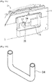
- a tube 34 is inserted and fixed in the first communication path 12, wherein the tube 34 corresponds to a tubular conduit.
- the second communication path 17 is divided by the tube 34.
- the second communication path 17 has a cross section in a U shape when viewing from the front side, and the same as the second communication path 17 according to the second embodiment, one end of the second communication path 17 is opened in the pump chamber 16 while the other end of the second communication path 17 is opened in the condensed water storage chamber 11.
- the opposite ends of the second communication path 17 are opened to the upper side.
- Each height of the opposite ends of the second communication path 17 are higher than the height in which the first communication path 12 is opened in the pump chamber 16 and the condensed water storage chamber 11.
- the clothes dryer D is capable of more reliably preventing the backflow and the scatter of the condensed water (W) although the fan device 10 having a high air flow rate is provided. That is, it is allowed that the air flow rate of the fan device 10 provided in the clothes dryer D is increased.
- the second communication path 17 is configured by the tube 34 mounted on the first communication path 12, and thus it is possible to minimize the change in the design around the ducts 5, 6 and 7 forming the circulation air flow path 8, so that the commonization of parts is obtained so as to reduce the manufacturing cost.
- the second communication path 17 is configured such that one end of the second communication path 17 is opened in the pump chamber 16 while the other end of the second communication path 17 is opened in the condensed water storage chamber 11 by mounting the partition member 33 or inserting the tube 34, but is not limited thereto.
- the second communication path 17 is configured by installing a through-hole on the rear wall portion 11 b.
- a member formed in a box shape similar with the rectangular shape is configured to be inserted and mounted to the rear wall portion 11 b of the condensed water storage chamber 11 has been described as an example of the partition member 33, but is not limited thereto.
- a space configured to push the condensed water W flowing the first communication path 12 is provided by using a wall portion standing adjacent to the first communication path 12, and the space is communicated with the condensed water storage chamber 11 and the pump chamber 16 so that the second communication path 17 is divided.
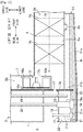
- the second communication path 17 according to the third embodiment is configured to allow the first air flow path 8a to be communicated with a space A except for the circulation air path to reduce the differential pressure between the condensed water storage chamber 11 and the pump chamber 16, which is different from the second communication path 17 according to the first and second embodiment.
- a through hole is installed in the rear wall portion 6h of the heat drying duct 6 to which the rear end of the cover base 6a is connected, and the rear end of the second communication path 17 divided by the through hole is opened to the atmosphere while the front end thereof is opened in the first air flow path 8a.
- the rear end of the second communication path 17 is opened on the rear surface of the body 1 around the pump chamber 16a, as illustrated in FIGS. 13A and13B and thus the first air flow path 8a is communicated with the space A except for the circulation air path in the body 1.
- the second communication path 17 is opened in the first air flow path 8a in the direction downstream than the drain hole 6b.
- the differential pressure is generated such that the pressure in the first air flow path 8a becomes the negative pressure and the pressure in the second air flow path 8b becomes the positive pressure.
- the pressure in the first air flow path 8a is adjusted to be close to the atmospheric pressure.
- the pressure in the condensed water storage chamber 11 is adjusted to be close to the atmospheric pressure by the communication with the first air flow path 8a through the drain hole 6b.
- the pressure in the pump chamber 16 becomes lager than the pressure in the condensed water storage chamber 11 (i.e., it is close to the atmospheric pressure) due to the communication between the pump chamber 16 and the first air flow path 8a through the condensed water storage chamber 11, and the air flowing into the pump chamber 16 from the outside A.
- the pressure in the condensed water storage chamber 11 is adjusted to be close to the atmospheric pressure by the installation of the second communication path 17 and thus the differential pressure between the pump chamber 16 and the condensed water storage chamber 11 is reduced.
- the first communication path 12 is closed by the condensed water W, but the second communication path 17 is configured to maintain the communication the outside A except for the circulation air path and the first air flow path 8a even when the first communication path 12 is closed, as illustrated in FIG. 12 . Therefore, when the first communication path 12 is submerged, the flow of air through the first communication path 12 is prevented but the flow of air through the second communication path 17 is maintained. Accordingly, although the first communication path 12 is submerged, the differential pressure between the pump chamber 16 and the condensed water storage chamber 11 is reduced.
- the first communication path 12 is submerged, it is possible to prevent the increase of the differential pressure between the pump chamber 16 and the condensed water storage chamber 11 and it is possible to prevent the difference in the water level of the condensed water W of the condensed water storage chamber 11 and the pump chamber 16.
- the pump 19 can be operated normally, and the backflow and the scatter of the condensed water W can more reliably be prevented.
- the clothes dryer D is capable of more reliably preventing the backflow and the scatter of the condensed water W although the fan device 10 having a high air flow rate is provided. That is, it is allowed that the air flow rate of the fan device 10 provided in the clothes dryer D is increased.
- the differential pressure between the space A except for the circulation air path and the pump chamber 16 is relatively reduced by maintaining the pressure in the pump chamber 16 at a relatively atmospheric pressure and thus it is possible to prevent the air from flowing from the outside A into the pump chamber 16. Therefore, e.g., when the first communication path 12 is not submerged, it is possible to prevent the atmosphere introduced into the pump chamber 16 from generating a wave on the surface of the condensed W in the condensed water storage chamber 11, which cause scattering of the condensed water W.
- the air flowing from the outside A directly flows into the first air flow path 8a through the second communication path 17 without passing through the condensed water storage chamber 11. Therefore, it is possible to prevent the atmosphere flowing into the pump chamber 16 from generating a wave on the surface of the condensed W in the condensed water storage chamber 11, which cause scattering of the condensed water W.
- the first air flow path 8a and the space A except for the circulation air path is directly connected, it is possible to prevent the condensed water W from back-flowing via the second communication path 17 or from submerging the second communication path 17 when the water level of the condensed water W in the pump chamber 16 is increased.
- the second communication path 17 Since the second communication path 17 is opened in the first air flow path 8a in the direct downstream than the drain hole 6b, the second communication path 17 is installed adjacent to the direct upstream of the fan device 10 than the drain hole 6b. Therefore, the differential pressure between the first air flow path 8a adjacent to the second communication path 17 and the space A except for the circulation air path is not relatively large, and thus it is possible to relatively immediately reduce the differential pressure between the pump chamber 16 and the condensed water storage chamber 11 by immediately allowing the pressure in the first air flow path 8a to be close the atmospheric pressure.
- the second communication path 17 is configured to be opened to the outside of the body 1, as illustrated in FIGS. 12 , 13A and 13B but according to the modification, the second communication path 17 is configured to be opened inside of the body 1, as illustrated in FIG. 14 . Accordingly, the second communication path 17 is not opened to the rear surface of the body 1, as illustrated in FIG. 15 .
- the second communication path 17 is configured to allow the first air flow path 8a to be communicated with a space A except for the circulation air path in the body 1 to reduce the differential pressure between the condensed water storage chamber 11 and the pump chamber 16.
- a through hole is installed in a rear wall portion 11 h of the condensed water storage chamber 11.
- the rear end of the second communication path 17 divided by the through hole is opened to the atmosphere while the front end thereof is opened in the condensed water storage chamber 11.
- the rear end of the second communication path 17 is opened on the rear surface of the body 1 around the pump chamber 16, as illustrated in FIG. 16 and thus the first air flow path 8a is communicated with the space A except for the circulation air path in the body 1.
- a height in which the second communication path 17 is opened in the condensed water storage chamber 11 is higher than a height in which the first communication path 12 is opened in the condensed water storage chamber 11, and the height is higher than the threshold level L in which the pump 19 starts to operate.
- the differential pressure is generated such that the pressure in the first air flow path 8a becomes the negative pressure and the pressure in the second air flow path 8b becomes the positive pressure.
- the pressure in the condensed water storage chamber 11 is adjusted to be close to the atmospheric pressure.
- the pressure in the pump chamber 16 becomes lager than the pressure in the condensed water storage chamber 11 (i.e., it is close to the atmospheric pressure) due to the communication between the pump chamber 16 and the first air flow path 8a through the condensed water storage chamber 11, and the air flowing into the pump chamber 16 from the outside A, as in the third embodiment.
- the pressure in the condensed water storage chamber 11 is adjusted to be close to the atmospheric pressure by the installation of the second communication path 17 and thus the differential pressure between the pump chamber 16 and the condensed water storage chamber 11 is reduced.
- the first communication path 12 is closed by the condensed water W, as illustrated in FIG. 16 , but the second communication path 17 is configured to maintain the communication the outside A except for the circulation air path and the first air flow path 8a even when the first communication path 12 is closed, as in the first to third embodiments. Therefore, when the first communication path 12 is submerged, the flow of air through the first communication path 12 is prevented but the flow of air through the second communication path 17 is maintained. Accordingly, although the first communication path 12 is submerged, the differential pressure between the pump chamber 16 and the condensed water storage chamber 11 is reduced.
- the clothes dryer D according to the fourth embodiment is capable of more reliably preventing the backflow and the scatter of the condensed water (W) although the fan device 10 having a high air flow rate is provided. That is, it is allowed that the air flow rate of the fan device 10 provided in the clothes dryer D is increased.
- the pressure in the condensed water storage chamber 11 is close to the atmospheric pressure by opening the condensed water storage chamber 11 to the atmosphere, it may be possible to maintain the pressure in the pump chamber 16 at the atmospheric pressure. Therefore, it may be possible to reduce the load of the pump 19 as in the third embodiment.
- the differential pressure between the space A except for the circulation air path and the pump chamber 16 is reduced and thus it is possible to prevent the air from flowing from the outside A into the pump chamber 16. Therefore, e.g., when the first communication path 12 is not submerged, it is possible to prevent the atmosphere introduced into the pump chamber 16 from generating a wave on the surface of the condensed W in the condensed water storage chamber 11, which cause scattering of the condensed water W.
- the second communication path 17 is configured to allow the air to flow between the space A except for the circulation air path and the condensed water storage chamber 11, and thus it is possible not to interrupt the flow A2 of the air for dying that flows in the first air flow path 8a.
- the height in which the second communication path 17 is opened in the condensed water storage chamber 11 is higher than the height in which the first communication path 12 is opened in the condensed water storage chamber 11, and the height is higher than the threshold level L in which the pump 19 starts to operate. Therefore, it is possible to prevent the condensed water W in the condensed water storage chamber 11 from flowing in the second communication path 17 or to prevent the second communication path 17 from being submerged. In addition, it is possible to maintain the communication by the second communication path 17.
- the second communication path 17 is configured to be opened to the outside of the body 1, as illustrated in FIG. 16 , but according to modification, the second communication path 17 is configured to be opened inside of the body 1, instead of the configuration thereof.
- the pressure in the condensed water storage chamber 11 may be lower than the pressure in the pump chamber 16.
- the pump 19 is properly operated according to the detection result of the clothes inlet 21 and thus it is prevent the backflow and scatter of the condensed water W.
- the second communication path 17 may be configured by combining the second communication path 17 according to the first to fourth embodiments.
- the shape and the configuration of the second communication path 17 according to the first to fourth embodiments are not limited thereto.
- the condensed water storage chamber 11 and the space A except for the circulation air path may be communicated with each other by a tube inserted into the rear wall portion 11 b instead of the through hole.
- a mesh type member may be mounted to the opening of the second communication path 17 to prevent the foreign material from entering to the pump chamber 16, the condensed water storage chamber 11 and the first air flow path 8a.
- An openable control valve may be installed in the second communication path 17.
- the control valve is configured to be opened or closed by the water level and the air pressure of the pump chamber 16 or the condensed water storage chamber 11, and the control valve is configured to be closed until a predetermined time is expired after the drying process starts.
- a rear side covering portion 36 that is separated from the covering portion 18 closing the pump chamber may be mounted to the rear surface of the body 1.
- the rear side covering portion 36 may be removable the same as the covering portion 18, and thus it is possible to improve the air tightness and to prevent foreign matters from entering into the pump chamber 16.
- the rear end of the second communication path 17 is opened on the rear surface of the body 1 as illustrated in the third and fourth embodiments, it is possible to prevent foreign matters from entering into the first air flow path 8a and the condensed water storage chamber 11 through the second communication path 17 by installing the rear side covering portion 36.
- the number, arrangement and shape of the drain hole 6b may vary. For example, it is possible to install another drain hole in the direct lower portion of the evaporator 9a or the condenser 9b.
- the opening 15 of the pump chamber 16 is closed by the removable covering portion 18, but is not limited thereto.
- the covering portion 18 and the pump chamber 16 are integrally formed.
- the other end of the water lift hose 20 may be connected to a component other than the water storage tank 25.
- the water lift hose 20 may be directly connected to the discharge pipe of the house, and it is possible to discharge the water through discharge pipe.
- the water level sensor 21 is not limited to the float type, and thus various sensors may be used. For example, it is possible to use the electrode sensor.
- the evaporator 9a and the condenser 9b forming the heat pump cycle 9 is used as the cooler and the heater, but is not limited thereto.
- an air cooled heat exchanger 27 may be used instead of the evaporator 9a as illustrated in FIG. 5 and an electric heater 28 may be used instead of the condenser 9b.
- the electric heater 28 may be installed in the second air flow path 8b and thus it is possible to prevent the electric heater 28 from effecting to the operation of the air cooled heat exchanger 27.
- the clothes dryer D configured to dry the clothes C, but is not limited thereto. Things other than the clothes may be an object to be dried.
Abstract
Description
- Embodiments disclosed herein relate to a clothes dryer capable of drying clothes.
- Conventionally, a circulation-type clothes dryer circulating dehumidified and heated air has been widely used. In such a dryer, a fan device for circulating air for drying, a cooling device for cooling and dehumidifying the air for drying, and a heating device for heating the air passing through the cooling device were all disposed in the circulation air flow path.
- In such a dryer, condensed water formed by dehumidification is attached to the surface of the cooling device in the form of droplets. As a result, a technique has been widely used wherein the technique is configured such that a condensed water container (drain pan) for collecting the condensed water is disposed and the condensed water recovered to the condensed water container is discharged to the outside or is stored in a separate water storage tank.
-
Patent document 1 discloses a technique of collecting condensed water dehumidified by a cooling device, in a drain pan and discharging the collected condensed water to the outside of a washing and drying machine by a pump. The drain pan is divided into a portion (hereinafter referred to as a condensed water storage chamber) communicated with an air flow path (hereinafter referred to as a first air flow path) in the side of the upstream of the fan device via a drain hole (opening), and a portion in which a pump is placed (hereinafter referred to as a pump chamber), wherein the condensed water storage chamber and the pump chamber are communicated with each other via a bottom portion thereof. Therefore, the condensed water collected in the condensed water storage chamber via the drain hole is stored in the pump chamber via the communicating portion (hereinafter referred to as a communication path)
Inpatent document 2, as another example of this technique, condensed water (dehumidified water) condensed in a cooling device (dehumidifying means) is recovered to a dehumidifying tank through a recovery flow path provided in the lower part of the cooling device, and the recovered condensed water is transferred to the water storage tank disposed above a body (a body of the clothes dryer) by a pump (water supply pump). Further, in the clothes dryer disclosed inpatent document 2, when it is detected that the condensed water in the tank has reached a certain water level, by a water level sensor provided in the dehumidifying tank, the pump is driven to discharge the condensed water in the dehumidifying tank. - It is conceivable that a wall portion configured to divide the pump chamber is provided with a removable covering portion for each pump section to improve the maintainability when using a pump chamber, as illustrated in patent document 1 (Japanese Patent Application Laid-Open No.
2011-239817 - However, the pump chamber configured as described above may not be constructed in a completely sealed structure, and thus a part of the pump chamber is exposed to the atmosphere. Accordingly, when the washing and drying machine using such a pump chamber starts to operate, the air pressure in both the pump chamber and the condensed water storage chamber becomes negative. However, the air pressure in the pump chamber is higher than the air pressure in the condensed water storage chamber since the pump chamber is communicated with the first air flow path through the condensed water storage chamber, and the atmosphere flows to the pump chamber, and thus the condensed water level stored in the pump chamber may become lower than the condensed water level stored in the condensed water storage chamber.
- Particularly, as the amount of the condensed water stored in the pump chamber increases, the communication path connecting the condensed water storage chamber to the pump chamber is submerged and blocked. Accordingly, the atmosphere flows to the pump chamber but the airflow between the pump chamber and the first air flow path is obstructed, thereby further increasing the differential pressure and the water level difference.
- It is conceivable to configure to lift the condensed water according to the water level sensor detection result provided in the pump chamber, such as a clothes dryer disclosed in patent document 2 (Japanese Patent Application Laid-Open No.
2014-33849 - It may be conceivable to additionally install a material, e.g., a packing, to a covering portion to reduce or to prevent the backflow, but in this case, a relatively high assembly degree is required, which increases the manufacturing cost. In addition, when the disassembled covering portion is assembled again since the assembly is defective when the time of manufacture or when parts are replaced, or for the maintenance, it is difficult to secure the desired airtightness, resulting in the inflow of air into the pump chamber, and further resulting in the backflow of the condensed water.
- Even if a material having a sufficient airtightness is installed, the pump chamber is exposed to the atmosphere through the water storage tank or the hose when the pump chamber is communicated with the additional water storage tank via the hose. Accordingly, the atmosphere flows into the pump chamber.
- That is, it may be difficult to completely prevent the backflow of the condensed water by a strategy of additionally installing the material, but it may cause the increase of the manufacturing cost.
- As another strategy, the length of the communication path connecting the condensed water storage chamber and the pump chamber is widened in the height direction so that the communication path is not submerged even if the condensed water increases. In this case, even when the water level of condensed water is increased, the airflow between the pump chamber and the circulation air flow path is maintained, so that an increase in the differential pressure can be suppressed. However, the air flows from the pump chamber side to the condensed water storage chamber side through the widely secured communication path, thereby causing a wave on the received condensed water surface, which causes scattering of the condensed water.
- In recent years, in order to improve the operating efficiency of the dryer, it is required to increase the air flow rate of the fan device. However, the air pressure at the upstream side of the fan device is further lowered due to the increase in the air flow rate, and thus the backflow of the condensed water easily occurs.
- Such a problem is not limited to a configuration in which the pump chamber is closed by the removable covering portion or a configuration in which the pump chamber is communicated with the water storage tank, and is related to the entirety of a dryer having a pump chamber in which at least a part thereof is communicated with the atmosphere.
- It is an aspect of the present disclosure to provide a clothes dryer capable of reliably preventing the backflow and the scattering of the condensed water generated by the dehumidification, and having a fan device having an increased air flow rate.
- One aspect of the present disclosure provides a clothes dryer including a body, a drum provided inside of the body, a fan device configured to circulate air for drying supplied to the drum, a circulation air flow path communicated with the drum and in which the air for drying is circulated by the fan device, a cooling device configured to dehumidify the air for drying by cooling the air for drying in the circulation air flow path, a condensed water storage chamber communicated with the circulation air flow path and configured to store condensed water generated by the cooling device, a pump chamber communicated with an outside space of the circulation air flow path and configured to accommodate a pump pumping the condensed water, a first communication path configured to flow the condensed water stored in the condensed water storage chamber to the pump chamber by allowing the condensed water storage chamber to be communicated with the pump chamber and a second communication path configured to allow the circulation air flow path to be communicated with at least one of the pump chamber and the outside space of the circulation air flow path.
- The circulation air flow path comprises a first air flow path communicated with the condensed water storage chamber to allow the air for drying passed through the drum to flow to the fan device, and a second air flow path provided to allow the air for drying passed through the fan device to flow to the drum, again.
- the second communication path maintains at least one communication among the first air flow path, the pump chamber and the outside space of the circulation air flow path, when the first air flow path is closed by the condensed water since the condensed water stored in the pump chamber is increased.
an opening of the second communication path is provided in a position higher than a position in which the first communication path is provided. - One end of the second communication path is opened in the pump chamber and other end of the second communication path is opened in the first air flow path.
- A drain portion configured to allow the condensed water storage chamber to be communicated with the first air flow path, and the second communication path is closer to the fan device than the drain portion.
One end of the second communication path is opened in the pump chamber and other end of the second communication path is opened in the condensed water storage chamber so that the pump chamber is communicated with the first air flow path through the condensed water storage chamber. - The second communication path is provided in a position higher than a position in which the first communication path is opened in the condensed water storage chamber.
- A portion of the second communication path penetrates the first communication path.
- The second communication path is formed in a tubular shape, and the second communication path comprises a curved portion so that the curved portion penetrates the first communication path.
- A partition member is provided in the first communication path to partition the first communication path, and thus the second communication path is provided between the first communication path by the partition member.
- One end of the second communication path is opened in the first air flow path and other end of the second communication path is opened in a rear side of the body.
- The second communication path is closer to the fan device than the drain portion configured to allow the condensed water storage chamber to be communicated with the first air flow path.
- One end of the second communication path is opened in the condensed water storage chamber and the other end of the second communication path is opened to the outside space of the body so that the first air flow path is communicated with the outside space of the body through the condensed water storage chamber.
- The pump chamber comprises an opening opened to the atmosphere, and a covering portion removably provided to close the opening of the pump chamber.
- A water storage tank storing condensed water pumped from the pump chamber; a connecting waterway connecting the pump and the water storage tank, and the pump chamber is communicated with the outside space of the circulation air flow path through the connecting waterway.
- One aspect of the present disclosure provides a clothes dryer including a drum, a circulation air flow path communicated with the drum and configured to allow air for drying to be circulated, the circulation air flow path provided with a first air flow path configured to allow the air for drying passed through the drum to be cooled and dehumidified, and a second air flow path configured to allow the dehumidified air for drying to flow to the drum, again, a condensed water storage chamber communicated with the first air flow path and configured to store condensed water generated by a cooling device, a pump chamber provided with an inlet port configured to allow condensed water stored in the condensed water storage chamber to be introduced and a pump configured to pump condensed water, the pump chamber communicated with the outside space of the circulation air flow path, and at least one communication path configured to introduce air to at least one of the first air flow path and the pump chamber to reduce the pressure difference between the condensed water storage chamber and the pump chamber.
- In order to reduce the pressure in the pump chamber by flowing the air to the pump chamber, one end of the at least one communication path is opened in the pump chamber and other end of the at least one communication path is opened in at least one of the inside of the first air flow path and the condensed water storage chamber.
- in order to increase the pressure in the condensed water storage chamber by flowing the air to the condensed water storage chamber, one end of the at least one communication path is opened in the first air flow path and other end of the at least one communication path is communicated with at least one of the inside of the pump chamber and the outside of the circulation air flow path.
- one end of the at least one communication path is opened in the condensed water storage chamber to be communicated with the first air flow path and the other end of the at least one communication path is communicated with the outside of the circulation air flow path.
- According to the proposed clothes dryer, it is possible to reliably prevent the backflow and the scattering of the condensed water, which is generated by the dehumidification, and it is possible to allow a fan device to have an increased air flow rate.
-
-
FIG.1 is longitudinal section views illustrating a clothes dryer with omitting some structure according to a first embodiment of the present disclosure. -
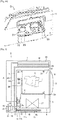
FIG.2 is enlarged longitudinal section views illustrating a condensed water storage chamber and a pump chamber for the clothes dryer according to a first embodiment of the present disclosure. .
.
-
FIG.3 is schematic views illustrating a the main part of the heat pump cycle for the clothes dryer according to a first embodiment of the present disclosure. -
FIG.4a is an enlarged perspective view showing a part of the structure of the pump chamber according to the first embodiment, -
FIG. 4b is an enlarged perspective view showing a state in which a lid is attached to the pump chamber according to the first embodiment. -
FIG. 5 is a view corresponding toFIG. 1 showing a modification of the clothes dryer according to the first embodiment, partially omitted. -
FIG. 6 is an enlarged perspective view showing a part of the bottom structure of the clothes dryer according to the first embodiment. -
FIG. 7 is a view corresponding toFIG. 2 showing a part of the structure of the pump chamber and the condensed water storage chamber according to the second embodiment. -
Fig. 8a is a view corresponding toFIG. 4a showing a part of the pump chamber structure according to the second embodiment -
FIG. 8b is a perspective view schematically showing the structure of the partition member according to the second embodiment. -
FIG. 9 is a view corresponding toFIG. 2 showing a part of the structure of the condensed water storage chamber and the pump chamber according to the first modified example of the second embodiment. -
FIG. 10a is a view corresponding toFIG. 4a showing a part of the structure of the pump chamber according to the first modification of the second embodiment. -
FIG. 10b is a view showing the structure of the tube according to the modification ofFIG 10a . -
FIG. 11 is a view corresponding toFIG. 2 showing a part of the structure of the condensed water storage chamber and the pump chamber according to the second modification of the second embodiment. -
FIG. 12 is a view corresponding toFIG. 2 showing a part of the structure of the condensed water storage chamber and the pump chamber according to the third embodiment. -
FIG. 13a shows a part of the structure of the pump chamber according to the third embodiment. -
FIG. 14 is a view corresponding toFIG. 2 showing a modification of the third embodiment. -
FIG. 15 is a view corresponding toFIG. 4a showing a part of the structure of the pump chamber according to the modification of the third embodiment. -
FIG. 16 is a view corresponding toFIG. 2 showing a part of the structure of the condensed water storage chamber and the pump chamber according to the fourth embodiment. - Hereinafter, embodiments of a dryer will be described with reference to the drawings. The following description of the embodiments is merely exemplary in nature.
- First, a first embodiment will be described.
- As illustrated in
FIG. 1 , a clothes dryer D as a dryer is provided with abody 1 having a vertically elongated rectangular parallelepiped shape extending along the vertical direction. Aclothes inlet 2 is opened in the upper part of the front surface of thebody 1, wherein theclothes inlet 2 is formed in a circular shape when viewing from the front side, and is opened or closed by apivotable covering portion 3. Adrum 4 corresponding to an object accommodating portion is communicated with theclothes inlet 2 to accommodate clothes C that is an object of drying, and thedrum 4 is rotatably supported in the upper portion of the inside of thebody 1. When the coveringportion 3 is opened, thedrum 4 may accommodate the clothes C put through theclothes inlet 2. - The
drum 4 is formed in cylindrical shape having a bottom having a rotary shaft center in the horizontal front and back direction. In a state in which an opening of thedrum 4 is toward theclothes inlet 2, the center of the bottom portion of thedrum 4 may be supported against a side wall portion of anintake side duct 7 to be rotatable via ashaft 30, and thedrum 4 may be rotated with respect to the rotary shaft center. Acirculation discharge port 31 discharging air used for drying the clothes C, and acirculation intake port 32 sucking the air used for drying the clothes C are communicated with thedrum 4. - The
shaft 30 is connected to a drum rotation motor (not shown) disposed in thebody 1 and is driven by the drum rotation motor when the clothes dryer D is operated to rotate thedrum 4 at a predetermined speed. It is possible to directly rotate thedrum 4 via a belt (not shown) by the rotation motor. - In the
body 1, adischarge side duct 5 whose one end is communicated with thecirculation discharge port 31 and theintake side duct 7 whose one end is communicated with thecirculation intake port 32, and aheat drying duct 6 connecting the other end of thedischarge side duct 5 to the other end of theintake side duct 7 are installed. An endless circulationair flow path 8 circulating the air for drying by passing through thedrum 4 is formed by a space in theducts lint filter 29 may be installed between theducts body 1. - Particularly, the
discharge side duct 5 is extended in the vertical direction on the front side in thebody 1. The upper end portion of thedischarge side duct 5 is connected to thecirculation discharge port 31 in a sealed manner. Theheat drying duct 6 is extended in the front and back direction on the bottom side (the lower side of the drum 4) in thebody 1 and an end portion of the front side is connected to the lower end portion of thedischarge side duct 5 in a sealed manner. Theintake side duct 7 is extended in the vertical direction on the rear side in thebody 1 and the lower end portion of theintake side duct 7 is connected to the rear end portion of theheat drying duct 6 in a sealed manner. In addition, the end portion of theintake side duct 7 is connected to thecirculation intake port 32 in a sealed manner. Thedrum 4 is connected to thecirculation discharge port 31 and thecirculation intake port 32 in a sealed manner or a freely rotatable manner. - As illustrated in
FIG. 2 , afan device 10 is installed in a connecting portion between theheat drying duct 6 and theintake side duct 7, which is the circulationair flow path 8 extending in the front and back direction in the lower portion of the clothes dryer D is curved toward the upper portion. Particularly, as illustrated inFIG. 2 , thefan device 10 is provided with acasing 10b and acylindrical impeller 10a rotatably supported in thecasing 10b to have a plurality of blades on a side surface thereof. Thecasing 10b is provided with anintake port 10c that opens in a direction parallel to the rotation axis of theimpeller 10a and adischarge port 10d that opens in a direction perpendicular to the rotation axis. Theintake port 10c and thedischarge port 10d are connected to the rear end of theheat drying duct 6 and the lower end of theintake side duct 7, respectively. In addition, for example, a centrifugal fan device having a multi-blade fan (sirocco fan) may be applied to thefan device 10. - As illustrated in
FIGS. 1 ,2 ,3 and6 , the circulationair flow path 8 is provided with anevaporator 9a composed of a heat exchanger as a cooling device for cooling and dehumidifying air, acondenser 9b as a heater heating the air passed through the cooling device. Theevaporator 9a and thecondenser 9b are installed and supported on acover base 6a corresponding to a supporting plate, in theheat drying duct 6. Theevaporator 9a is installed in the upstream side (front side) of the circulationair flow path 8 and thecondenser 9b is installed in the downstream (rear side) of the evaporator 9a to be apart from theevaporator 9a by a predetermined distance. - The circulation
air flow path 8 is provided with a firstair flow path 8a in which the air for drying passing through thedrum 4 flows to thefan device 10 by passing through theevaporator 9a and thecondenser 9b in order, and a secondair flow path 8b separated from the firstair flow path 8a, and in which the air for drying passing through thefan device 10 flows to thedrum 4. According to the first embodiment, the firstair flow path 8a is formed by thedischarge side duct 5 and theheat drying duct 6 and the secondair flow path 8b is formed by theintake side duct 7. By the operation of thefan device 10, the firstair flow path 8a becomes the negative pressure while the secondair flow path 8b becomes the positive pressure. The size of the negative pressure and the positive pressure, that is the magnitude of the differential pressure between the atmospheric pressure and the air pressure in the firstair flow path 8a or the secondair flow path 8b, increases from thedrum 4 toward thefan device 10, respectively. - As illustrated in
FIG. 3 , in the clothes dryer D, acompressor 9c and adecompressor 9d are provided in thebody 1, theevaporator 9a, thecompressor 9c, and thecondenser 9b, and thedecompressor 9d are connected in order via arefrigeration pipe 9e so that aheat pump cycle 9 is formed. According to the above mentioned configuration, theevaporator 9a and thecondenser 9b exchange heat between the air flowing into theheat drying duct 6. - As illustrated in
FIG. 3 , when theheat pump cycle 9 is operated, gas refrigerant, which is discharged from thecompressor 9c and at a high temperature and a high pressure, becomes liquid refrigerant at a low temperature and a low pressure after being condensed in thecondenser 9b and expanded in thedecompressor 9d. The liquid refrigerant is evaporated in theevaporator 9a and then returns to thecompressor 9c. As a result, the air is cooled and dehumidified by the evaporation heat generated when the refrigerant passes through theevaporator 9a, while the air is heated by the condensation heat generated when the refrigerant passes through thecondenser 9b. - As illustrated in
FIGS. 1 ,2 , and6 , a condensedwater storage chamber 11 collecting and storing the condensed water W generated in theevaporator 9a is provided below theheat drying duct 6. The condensedwater storage chamber 11 is opened upward and an opening thereof is closed by thecover base 6a. Theheat drying duct 6 and the condensedwater storage chamber 11 is partitioned by thecover base 6a. - A
drain hole 6b is formed in thecover base 6a as a drain portion corresponding to a communication path penetrating in the vertical direction directly below theevaporator 9a. The condensed water W, which is generated when the air for drying in the firstair flow path 8a is dehumidified by theevaporator 9a, is discharged to the condensedwater storage chamber 11 through thedrain hole 6b. Thecover base 6a is inclined toward the lower side as it approaches thedrain hole 6b from the lower side of theevaporator 9a (seeFIGS. 2 and6 ), and thecover base 6a guides the condensed water W dropped around thedrain hole 6b to thedrain hole 6b. - The condensed
water storage chamber 11 is communicated with the firstair flow path 8a by thedrain hole 6b and collects the condensed water W through thedrain hole 6b. As illustrated inFIGS. 2 and6 , abottom surface 11 a of the condensedwater storage chamber 11 is inclined downward from the front side toward the rear side, so that the collected condensed water W flows backward. The width of the condensedwater storage chamber 11 in the left-right direction is narrowed as being near the rear side, as shown inFIG. 6 , so that the condensed water W more stably flows as being near the rear side. - According to the embodiment, the clothes dryer (D) includes a
pump chamber 16 containing apump 19 pumping the condensed water W collected in the condensedwater storage chamber 11. Thepump chamber 16 is mounted on the rear lower portion of thebody 1 and communicated with the condensedwater storage chamber 11 through a first communication path 12 (i.e., an inlet, hereinafter referred to as a first communication path). - Particularly, as illustrated in
FIGS. 2 and6 , on awall portion 11 b in the rear side of the condensed water storage chamber 11 (hereinafter referred to as a rear wall portion), thefirst communication path 12 penetrating the lower portion of therear wall portion 11 b is formed and a rear end portion of the condensedwater storage chamber 11 and a front end portion of thepump chamber 16 is integrally connected to each other by thefirst communication path 12. Thefirst communication path 12 is formed as a through-hole extending substantially in the front and back direction and thefirst communication path 12 is configured to allow the condensedwater storage chamber 11 to be communicated with thepump chamber 16 through the bottom portions thereof. The condensed water W flowing from the condensedwater storage chamber 11 is guided to thepump chamber 16 by thefirst communication path 12. As shown inFIGS. 2 and6 , the height at which thefirst communication path 12 is opened in the condensedwater storage chamber 11 is lower than the lower end of thedrain hole 6b. - The
pump chamber 16 is opened toward the upper side and defines a space in the form of a horizontally long rectangular parallelepiped which is communicated with the space outside of thebody 1 through theopening 15 as shown inFIGS. 4 A and 6. Thepump chamber 16 is equipped with aremovable covering portion 18 configured to close theopening 15 in a substantially sealed manner. The coveringportion 18 is formed to be fittable around theopening 15 of thepump chamber 16 and the coveringportion 18 is mounted to theopening 15 by being coupled to theopening 15. In the around of the rear surface of the coveringportion 18, a material (not shown) formed of a soft material having a viability such as natural rubber and soft resin is mounted and thus when the coveringportion 18 is fitted into theopening 15, theopening 15 is closed in a substantially sealed manner. - As illustrated in
FIG. 4B , thepump 19 pumping the condensed water W accommodated in thepump chamber 16 is mounted on the right portion of the coveringportion 18, and awater level sensor 21 corresponding to a water level detector detecting the water level of the water in thepump chamber 16 is mounted on the left portion of the coveringportion 18. In addition, ahose connecting hole 23 is formed at a substantially central portion on the front portion of the coveringportion 18 in the left-right direction. As illustrated inFIGS. 1 and2 , a leak-proof hose 24 is inserted in thehose connecting hole 23 in the liquid-tight state (not shown inFIGS. 4B and6 ). Thepump 19, thewater level sensor 21 and the leak-proof hose 24 may be individually detachable from the coveringportion 18, respectively. - The
pump 19 is a water lift type submersible pump and has apump casing 19a provided with an absorption port and a discharge port (both not shown). Thepump 19 is fixed to the coveringportion 18 such that the absorption port is located near the bottom of thepump chamber 16 while the discharge port is located above the coveringportion 18. The condensed water W stored in thepump chamber 16 is pumped by the operation of thepump 19. - One end of a water lift hose 20 (e. g, a synthetic resin product) corresponding to a connecting waterway is connected to the discharge port of the
pump 19. As illustrated inFIG. 1 , the other end of thewater lift hose 20 is connected to the additionalwater storage tank 25 and then delivers the condensed water W pumped from thepump chamber 16 to thewater storage tank 25. Thewater storage tank 25 is disposed above thedrum 4 in thebody 1 and thus as needed, thewater storage tank 25 may be pulled out from thebody 1. - The
water storage tank 25 is installed in a condensed water storage chamber for astorage water tank 26 formed in the accommodation container shape, and the condensed water W overflowing from thewater storage tank 25 is stored in the condensed water storage chamber for thewater storage tank 26. The leak-proof hose 24 is connected to the bottom of the condensed water storage chamber for thewater storage tank 26, as illustrated inFIGS. 1 and2 , and the condensed water W overflowing from thewater storage tank 25 is returned to thepump chamber 16 via the leak-proof hose 24. In the clothes dryer D according to the embodiment, thepump chamber 16 and a space A except for the circulation air flow path are communicated with each other through the condensed water storage chamber for thewater storage tank 26 and the leak-proof hose 24. In addition, for the convenience of description,FIG. 1 illustrates thewater lift hose 20 and the leak-proof hose 24 are disposed in the rear side of theintake side duct 7, but thewater lift hose 20 and the leak-proof hose 24 may be disposed in the left side or the right side of theintake side duct 7. - The
water level sensor 21 has atubular stem 21 b hanged on thepump chamber 16 from the coveringportion 18 and afloat 21 a supported by thestem 21 b to be vertically movable within a predetermined range with respect to thestem 21 b. Thewater level sensor 21 senses the water level by the height of thefloat 21 a. According to the embodiment, the clothes dryer D includes a controller (not shown). The controller operates thepump 19 when the water level sensed by thewater level sensor 21 exceeds a predetermined threshold level L . - As illustrated in
FIGS. 2 ,4A and6 , asecond communication path 17 is installed in the lower end portion of therear wall portion 6h of theheat drying duct 6 to which the rear end of thecover base 6a is connected, wherein thesecond communication path 17 is a through hole type elongating in the left and right direction and extending in the front and back direction. The rear end of thesecond communication path 17 is opened in thepump chamber 16 while the front end of thesecond communication path 17 is opened in the firstair flow path 8a. Thesecond communication path 17 allows the firstair flow path 8a to be communicated with thepump chamber 16 to reduce the differential pressure between the condensedwater storage chamber 11 and thepump chamber 16. - The second communication path 17 (i.e., a communication path, hereinafter referred to as a second communication path) is opened in the
pump chamber 16 in a position higher than a position in which thefirst communication path 12 is opened in thepump chamber 16, as illustrated inFIGS. 2 and6 . In addition, thesecond communication path 17 is configured such that a height in which thesecond communication path 17 is opened in thepump chamber 16 and a height in which thesecond communication path 17 is opened in the condensedwater storage chamber 11 are higher than the threshold level L in which thepump 19 starts to operate. - As illustrated in
FIGS. 2 and6 , thesecond communication path 17 is opened into the firstair flow path 8a in the direct downstream than thedrain hole 6b. - Next, the operation of the clothes dryer D according to the present embodiment will be described.
- First, when the clothes dryer D starts to operate, the drum rotation motor, the
fan device 10 and theheat pump cycle 9 operate. A pressure difference occurs such that in the circulationair flow path 8, the firstair flow path 8a becomes the negative pressure and thesecond air path 8b becomes the positive pressure by the operation of thefan device 10. For example, the air pressure on the direct upstream side of thefan device 10 may be lower than the atmospheric pressure by 300 Pa or more. The air in thedrum 4 circulates in the circulationair flow path 8 as the air for drying in accordance with the differential pressure. - Particularly, as illustrated by arrows A1 and A 2 in
FIG. 1 , the air for drying in thedrum 4 flows into thedischarge side duct 5 through thecirculation discharge port 31, and then flows toward the lower portion in the front side of thebody 1 and then flows into theheat drying duct 6. - As illustrated by the
arrow A 2 inFIG. 1 , the air introduced into theheat drying duct 6 flows the lower side of thebody 1 toward the rear side along theheat drying duct 6. In theheat drying duct 6, theevaporator 9a and thecondenser 9b constituting theheat pump cycle 9 are disposed in order in the downstream of theheat drying duct 6. Therefore, as the air for drying passes through theheat drying duct 6, the air for drying is cooled and dehumidified in theevaporator 9a, and then heated in thecondenser 9b so as to be adjusted to a state suitable for drying the clothes C. - Since the
intake port 10c and thedischarge port 10d of thefan device 10 face theheat drying duct 6 and theintake side duct 7, the air for drying that is passed through theheat drying duct 6 is passed through inside of thefan device 10 and delivered, and introduced into theintake side duct 7 as illustrated by the arrows A2 and A3 ofFIG. 1 . As illustrated by the arrow A3 ofFIG.1 , the air for drying flowing into theintake side duct 7 flows to the upper portion in the rear side of thebody 1 along theintake side duct 7 and then flows into thedrum 4 through thecirculation intake port 32. - By repeating the circulation process as described above, the air for drying is maintained at a predetermined humidity and temperature while the clothes dryer D operates, thereby drying the clothes C in the
drum 4. Since thedrum 4 is rotated at a predetermined speed by driving the drum rotation motor (not shown) during the operation of the clothes dryer D, the clothes C in thedrum 4 are agitated, so that the air for drying is uniformly supplied to the clothes C in thedrum 4. - When the circulation process is repeated, the condensed water W in the form of water droplets, which is generated by the dehumidification, is attached to the surface of the
evaporator 9a. The attached condensed water W is dropped and led to thedrain hole 6b in accordance with the inclination of thecover base 6a and flows from thedrain hole 6b to the condensedwater storage chamber 11. The condensed water W flowing into the condensedwater storage chamber 11 flows to the rear side along thebottom surface 11 a of the condensedwater storage chamber 11 and is supplied to and stored in thepump chamber 16 through thefirst communication path 12 . - When the circulation process is further repeated, the water level of the condensed water stored in the
pump chamber 16, thefirst communication path 12, and the condensedwater storage chamber 11 rises. When thewater level sensor 21 detects that the water level in thepump chamber 16 has reached the water level equal to or higher than the predetermined threshold level L, the controller operates thepump 19. The condensed water W accommodated in thepump chamber 16 and the condensedwater storage chamber 11 is pumped by the operatedpump 19 and transferred to thewater storage tank 25 through thewater lift hose 20. - Since the first
air flow path 8a is communicated with the condensedwater storage chamber 11 through thedrain hole 6b, the pressure in the condensedwater storage chamber 11 is adjusted to be close to the negative pressure in the firstair flow path 8a. Meanwhile, the condensedwater storage chamber 11 is communicated with thepump chamber 16 through thefirst communication path 12. When the firstair flow path 8a, the condensedwater storage chamber 11, thepump chamber 16 are communicated with each other by using only thedrain hole 6b and thefirst communication path 12 as described inpatent document 1, the pressure in thepump chamber 16 becomes larger than the pressure in the condensed water storage chamber 11 (i.e., it is close to the atmospheric pressure) since thepump chamber 16 is communicated with the firstair flow path 8a through the condensedwater storage chamber 11, and due to the atmosphere flowing into thepump chamber 16 from the space A except for the circulation air flow path (hereinafter referred to as outside A). However, according to the first embodiment, since thepump chamber 16 is provided with thesecond communication path 17, the air pressure in thepump chamber 16 is adjusted to be close to the negative pressure in the firstair flow path 8a by the flow of air through thefirst communication path 12 and further the flow of air through thesecond communication path 17. Accordingly, the differential pressure between thepump chamber 16 and the condensedwater storage chamber 11 is reduced. - As the amount of the condensed water W accommodated in the
pump chamber 16 and the condensedwater storage chamber 11 increases, thefirst communication path 12 is closed by the condensed water W, but thesecond communication path 17 maintains the communication between thepump chamber 16 and the firstair flow path 8a even when thefirst communication path 12 is closed (submerged), as illustrated inFIGS. 1 and2 . Therefore, when thefirst communication path 12 is submerged, the flow of air through thefirst communication path 12 is prevented but the flow of air through thesecond communication path 17 is maintained. Accordingly, although thefirst communication path 12 is submerged, the differential pressure between thepump chamber 16 and the condensedwater storage chamber 11 is reduced. It is possible to prevent the difference in the water level of the condensed water W of the condensedwater storage chamber 11 and thepump chamber 16 so as to prevent the increase of the differential pressure between thepump chamber 16 and the condensedwater storage chamber 11 and to allow the water level in thepump chamber 16 to be relatively high while allowing the water level in the condensedwater storage chamber 11 to be relatively low. As a result, thepump 19 can be operated normally, and the backflow and the scatter of the condensed water W may be more reliably prevented. - As described above, according to the first embodiment, the clothes dryer D is capable of more reliably preventing the backflow and the scatter of the condensed water W although the
fan device 10 having a high air flow rate is provided. That is, it is allowed that the air flow rate of thefan device 10 provided in the clothes dryer D is increased. - Since the
pump chamber 16 and the firstair flow path 8a are directly communicated with each other, when the air is introduced into thepump chamber 16, at least a part of the air flows into the firstair flow path 8a through thesecond communication path 17 to be sucked into the firstair flow path 8a. Since the air flowing into the firstair flow path 8a increases the pressure in the firstair flow path 8a and then the pressure in the condensedwater storage chamber 11 in order, when the pressure in thepump chamber 16 is increased by the introduction of the air, it is possible to also increase the pressure in the condensedwater storage chamber 11. Therefore, it is possible to prevent the differential pressure between thepump chamber 16 and the condensedwater storage chamber 11. - When the atmosphere is introduced into the
pump chamber 16, the atmosphere is introduced into the firstair flow path 8a through thesecond communication path 17 or the increase of the differential pressure is prevented. Therefore, it is possible to prevent the atmosphere introduced into thepump chamber 16 from scattering of the condensed water W caused by a wave on the surface of the condensed W in the condensedwater storage chamber 11. - Further, the condensed water W, which is overflowed from the
water storage tank 25 due to unforeseen events, falls and flows over the condensed water storage chamber for thewater storage tank 26 installed in the lower side of thewater storage tank 25, and then returns to thepump chamber 16 through the leak-proof hose 24. - Since it is possible for the pressure in the
pump chamber 16 to be close to the negative pressure in the firstair flow path 8a since the firstair flow path 8a is communicated with thepump chamber 16, it is possible to prevent the increase of the pressure in the firstair flow path 8a and further in the secondair flow path 8b. Accordingly, it is possible to prevent the leakage of the air for drying in the eachduct - Since the height in which the
second communication path 17 is opened in thepump chamber 16 is higher than the height in which thefirst communication path 12 is opened in thepump chamber 16, it is prevented that the condensed water (W) in thepump chamber 16 is reverse-flowed via thesecond communication path 17 or the condensed water W in thepump chamber 16 submerges thesecond communication path 17, so that the communication by thesecond communication path 17 is maintained. - The
second communication path 17 is configured such that the position in which thesecond communication path 17 is opened in the firstair flow path 8a is closer to the direction upstream of thefan device 10 than thedrain hole 6b. Particularly, as illustrated inFIGS. 1 and2 , while thedrain hole 6b is installed on thecover base 6a, thesecond communication path 17 is formed on therear wall portion 6h which is closer to thefan device 10 than thedrain hole 6b. Therefore, since thesecond communication path 17 is closer to thefan device 10 than thedrain hole 6b, the ambient atmospheric pressure of thesecond communication path 17 is lower than the ambient atmospheric pressure of thedrain hole 6b. Accordingly, it is possible to maintain thepump chamber 16 at the low pressure and further it is possible to maintain the high water level of thepump chamber 16. - Both of the height in which the
second communication path 17 is opened in thepump chamber 16 and the height in which thesecond communication path 17 is opened in the condensedwater storage chamber 11 are higher than the water level threshold value in which thepump 19 starts to operate and thus it is prevented that the condensed water (W) in thepump chamber 16 is reverse-flowed via thesecond communication path 17 or the condensed water W in thepump chamber 16 submerges thesecond communication path 17, so that the communication by thesecond communication path 17 is maintained. - Further, since the
opening 15 of thepump chamber 16 is closed by thecover portion 18 in the substantially sealed manner, the air is prevented from flowing into thepump chamber 16. Therefore, it is possible to prevent the increase of the pressure in thepump chamber 16 and further to maintain the high water level in thepump chamber 16. - The
evaporator 9a and thecondenser 9b forming theheat pump cycle 9 are used as a cooling device and a heating device. In this case, since the heat exchange efficiency between the air for drying, and theevaporator 9a and thecondenser 9b is improved as the air flow rate of the air flowing in the circulationair flow path 8 is increased, it is possible to obtain the effect of the installation of thefan device 10 having the high air flow rate. - Since the condensed
water storage chamber 11 and theheat drying duct 6 are separated by thecover base 6a supporting theevaporator 9a and thecondenser 9b, it is possible to prevent the flow of the air for drying, wherein the air for drying is introduced from the condensedwater storage chamber 11 in the front side of theevaporator 9a and then introduced into thefan device 10 through the condensedwater storage chamber 11. - According to the first embodiment, the height in which the
second communication path 17 is opened in thepump chamber 16 is higher the height in which thefirst communication path 12 is opened in thepump chamber 16, but is not limited thereto. For example, a space configured to push the condensed water W flowing into thepump chamber 16 is provided by using a wall portion standing in thepump chamber 16, and the space is communicated with the firstair flow path 8a so that thesecond communication path 17 is formed. According to the above mentioned configuration, thesecond communication path 17 may be opened in thepump chamber 16 in a position lower than a position in which thefirst communication path 12 is opened in thepump chamber 16. - According to the configuration, it may be possible to adjust the threshold level L in which the
pump 19 starts to operate. - Hereinafter according to the second embodiment, a clothes dryer D will be described. The following description explains the difference in the operation of between the first and second embodiments, and the effect obtained by the difference.
- As illustrated in
FIG. 7 , according to the second embodiment, thefirst communication path 12 is recessed downward in the height direction than thefirst communication path 12 according to the first embodiment, and apartition member 33 as illustrated inFIG. 8B is mounted on therear wall portion 11 b of the condensedwater storage chamber 11. - As illustrated in
FIG. 8B , thepartition member 33 is formed in a box shape similar with the rectangular shape having an opened top surface. In thepartition member 33,notch portions 33a are installed in opposite sides of the left and right wall portion thereof, wherein thenotch portion 33a has a cross-section in the U shape that is notched from the top to the lower side. - The
partition member 33 is fixed by inserting twonotch portions 33a into the lower portion of therear wall portion 11 b. The communication path corresponding to the first communication path according to the first embodiment is divided into awater passage 12 formed by abottom surface 11 a of the condensedwater storage chamber 11, a bottom surface of thepump chamber 16 and an external wall portion of thepartition member 33, and aventilation path 17 formed by an internal wall portion of thepartition member 33 and therear wall portion 11 b, as illustrated inFIGS. 7 and8A . - The
water passage 12 forms thefirst communication path 12 according to the second embodiment. That is, thewater passage 12 is configured to allow the condensedwater storage chamber 11 to be communicated with thepump chamber 16 through each bottom portion thereof, and configured to guide the condensed water W in the condensedwater storage chamber 11 into thepump chamber 16. - As illustrated in
FIG. 7 , theventilation path 17 forms a path in a "" shape in which the upper side is opened when viewing from the left side or the right side, and is configured to vent between the condensed
water storage chamber 11 and thepump chamber 16. Theventilation path 17 forms thesecond communication path 17 according to the second embodiment and is configured to allow the firstair flow path 8a to be communicated with thepump chamber 16 through the condensedwater storage chamber 11 so as to reduce the differential pressure between thepump chamber 16 and the condensedwater storage chamber 11. - Therefore hereinafter, the
water passage 12 and theventilation path 17 will be referred to as thefirst communication path 12 and thesecond communication path 17 according to the second embodiment, or just "thefirst communication path 12 and thesecond communication path 17" - Particularly, according to the second embodiment, the rear end of the
second communication path 17 is opened in thepump chamber 16 and the front end of thesecond communication path 17 is opened in the condensedwater storage chamber 11. Accordingly, the firstair flow path 8a is communicated with thepump chamber 16 via the condensedwater storage chamber 11. - The opposite ends of the
second communication path 17 are opened to the upper side and each height of the opposite ends of thesecond communication path 17 are higher than the height in which thefirst communication path 12 is opened in thepump chamber 16 and the condensedwater storage chamber 11. - The opposite ends of the
second communication path 17 are opened at a position higher than the threshold level L in which thepump 19 starts to operate. - According to the second embodiment, when the clothes dryer D starts to operate, the pressure in the
pump chamber 16 is adjusted to be close to the negative pressure in the condensedwater storage chamber 11 by the flow of air between thepump chamber 16 and the condensedwater storage chamber 11 through thefirst communication path 12 or thesecond communication path 17. Meanwhile, the pressure in the condensedwater storage chamber 11 is adjusted to be close to the negative pressure in the firstair flow path 8a through the communication by thedrain hole 6b, as illustrated in the first embodiment. As in the first embodiment, as the amount of the condensed water W accommodated in thepump chamber 16 and the condensedwater storage chamber 11 increases, thefirst communication path 12 is closed by the condensed water W, but thesecond communication path 17 is configured to maintain the communication between thepump chamber 16 and the condensedwater storage chamber 11. As illustrated inFIG. 7 , when thefirst communication path 12 is submerged, the flow of air through thefirst communication path 12 is blocked but the flow of air through thesecond communication path 17 is maintained. Accordingly, the differential pressure between thepump chamber 16 and the condensedwater storage chamber 11 is reduced by the flow of air through thesecond communication path 17. It is possible to prevent the increase of the differential pressure between thepump chamber 16 and the condensedwater storage chamber 11 and to prevent the difference in the water level of the condensed water W of the condensedwater storage chamber 11 and thepump chamber 16. As a result, thepump 19 can be operated normally, and the backflow and the scatter of the condensed water W can be prevented. - As described above, as in the first embodiment, the clothes dryer D according to the second embodiment is capable of more reliably preventing the backflow and the scatter of the condensed water (W) although the
fan device 10 having a high air flow rate is provided. That is, it is allowed that the air flow rate of thefan device 10 provided in the clothes dryer D is increased. - Since the
pump chamber 16 and the firstair flow path 8a are communicated with each other via the condensedwater storage chamber 11, as in the first embodiment, it is possible to prevent the increase of the pressure in the firstair flow path 8a and further in the secondair flow path 8b. Accordingly, it is possible to prevent the leakage of the air for drying in the eachduct - According to the second embodiment, the
second communication path 17 is configured to allow the flow of air between thepump chamber 16 and the condensedwater storage chamber 11 and thus it is possible not to interrupt the flow A2 of the air for dying that flows in the firstair flow path 8a. - According to the second embodiment, the
first communication path 12 and thesecond communication path 17 are configured by thepartition member 33 mounted on therear wall portion 11 b, and thus it is possible to minimize the change in the design around theducts air flow path 8, so that the commonization of parts is obtained so as to reduce the manufacturing cost. - Since the opposite ends of the
second communication path 17 are provided to be higher than thefirst communication path 12, it is prevented that the condensed water W in thepump chamber 16 is reverse-flowed or thesecond communication path 17 is submerged. In addition, the communication of thesecond communication path 17 is maintained. - Since the opposite openings of the
second communication path 17 are provided to face the upper side, it is prevented that the condensed water W in thepump chamber 16 is reverse-flowed or thesecond communication path 17 is submerged, and the communication of thesecond communication path 17 is maintained, in comparison with the configuration in which the opening of thesecond communication path 17 faces the lower side or the front, back, left and right directions. - Since the opposite ends of the
second communication path 17 are opened in a position higher than the threshold level L in which thepump 19 starts to operate, it is prevented that the condensed water W in thepump chamber 16 is reverse-flowed or thesecond communication path 17 is submerged. In addition, the communication of thesecond communication path 17 is maintained. - Hereinafter a first modification of the second embodiment will be described.
- As illustrated in
FIGS. 9 ,10A and 10B , atube 34 is inserted and fixed in thefirst communication path 12, wherein thetube 34 corresponds to a tubular conduit. According to the first modification, thesecond communication path 17 is divided by thetube 34. - As illustrated in
FIG. 9 , thesecond communication path 17 has a cross section in a U shape when viewing from the front side, and the same as thesecond communication path 17 according to the second embodiment, one end of thesecond communication path 17 is opened in thepump chamber 16 while the other end of thesecond communication path 17 is opened in the condensedwater storage chamber 11. The opposite ends of thesecond communication path 17 are opened to the upper side. Each height of the opposite ends of thesecond communication path 17 are higher than the height in which thefirst communication path 12 is opened in thepump chamber 16 and the condensedwater storage chamber 11. - According to the modification, as in the second embodiment, the clothes dryer D is capable of more reliably preventing the backflow and the scatter of the condensed water (W) although the
fan device 10 having a high air flow rate is provided. That is, it is allowed that the air flow rate of thefan device 10 provided in the clothes dryer D is increased. - According to the modification, the
second communication path 17 is configured by thetube 34 mounted on thefirst communication path 12, and thus it is possible to minimize the change in the design around theducts air flow path 8, so that the commonization of parts is obtained so as to reduce the manufacturing cost. - According to the second embodiment and the first modification of the second embodiment, the
second communication path 17 is configured such that one end of thesecond communication path 17 is opened in thepump chamber 16 while the other end of thesecond communication path 17 is opened in the condensedwater storage chamber 11 by mounting thepartition member 33 or inserting thetube 34, but is not limited thereto. For example, as illustrated inFIG. 11 , thesecond communication path 17 is configured by installing a through-hole on therear wall portion 11 b. - According to the second embodiment, a member formed in a box shape similar with the rectangular shape is configured to be inserted and mounted to the
rear wall portion 11 b of the condensedwater storage chamber 11 has been described as an example of thepartition member 33, but is not limited thereto. For example, a space configured to push the condensed water W flowing thefirst communication path 12 is provided by using a wall portion standing adjacent to thefirst communication path 12, and the space is communicated with the condensedwater storage chamber 11 and thepump chamber 16 so that thesecond communication path 17 is divided. - Hereinafter according to the third embodiment, a clothes dryer D will be described. As illustrated in
FIGS. 12 ,13A and 13B , thesecond communication path 17 according to the third embodiment is configured to allow the firstair flow path 8a to be communicated with a space A except for the circulation air path to reduce the differential pressure between the condensedwater storage chamber 11 and thepump chamber 16, which is different from thesecond communication path 17 according to the first and second embodiment. - Particularly, a through hole is installed in the
rear wall portion 6h of theheat drying duct 6 to which the rear end of thecover base 6a is connected, and the rear end of thesecond communication path 17 divided by the through hole is opened to the atmosphere while the front end thereof is opened in the firstair flow path 8a. Particularly, the rear end of thesecond communication path 17 is opened on the rear surface of thebody 1 around the pump chamber 16a, as illustrated inFIGS. 13A and13B and thus the firstair flow path 8a is communicated with the space A except for the circulation air path in thebody 1. - The
second communication path 17 is opened in the firstair flow path 8a in the direction downstream than thedrain hole 6b. - According to the third embodiment, when the clothes dryer D starts to operate, the differential pressure is generated such that the pressure in the first
air flow path 8a becomes the negative pressure and the pressure in the secondair flow path 8b becomes the positive pressure. However, by the air flowing into the firstair flow path 8a from the space A except for the circulation air path passing through thesecond communication path 17, the pressure in the firstair flow path 8a is adjusted to be close to the atmospheric pressure. Meanwhile, the pressure in the condensedwater storage chamber 11 is adjusted to be close to the atmospheric pressure by the communication with the firstair flow path 8a through thedrain hole 6b. The pressure in thepump chamber 16 becomes lager than the pressure in the condensed water storage chamber 11 (i.e., it is close to the atmospheric pressure) due to the communication between thepump chamber 16 and the firstair flow path 8a through the condensedwater storage chamber 11, and the air flowing into thepump chamber 16 from the outside A. However, the pressure in the condensedwater storage chamber 11 is adjusted to be close to the atmospheric pressure by the installation of thesecond communication path 17 and thus the differential pressure between thepump chamber 16 and the condensedwater storage chamber 11 is reduced. - As the amount of the condensed water W accommodated in the
pump chamber 16 and the condensedwater storage chamber 11 increases, thefirst communication path 12 is closed by the condensed water W, but thesecond communication path 17 is configured to maintain the communication the outside A except for the circulation air path and the firstair flow path 8a even when thefirst communication path 12 is closed, as illustrated inFIG. 12 . Therefore, when thefirst communication path 12 is submerged, the flow of air through thefirst communication path 12 is prevented but the flow of air through thesecond communication path 17 is maintained. Accordingly, although thefirst communication path 12 is submerged, the differential pressure between thepump chamber 16 and the condensedwater storage chamber 11 is reduced. Therefore, although thefirst communication path 12 is submerged, it is possible to prevent the increase of the differential pressure between thepump chamber 16 and the condensedwater storage chamber 11 and it is possible to prevent the difference in the water level of the condensed water W of the condensedwater storage chamber 11 and thepump chamber 16. As a result, thepump 19 can be operated normally, and the backflow and the scatter of the condensed water W can more reliably be prevented. - According to the third embodiment, as in the first embodiment, the clothes dryer D is capable of more reliably preventing the backflow and the scatter of the condensed water W although the
fan device 10 having a high air flow rate is provided. That is, it is allowed that the air flow rate of thefan device 10 provided in the clothes dryer D is increased. - Since the pressure in the first
air flow path 8a and the pressure in the condensedwater storage chamber 11 are is closed to the atmospheric pressure by opening the firstair flow path 8a to the atmosphere, it may be possible to maintain the pressure in thepump chamber 16 at the atmospheric pressure. Therefore, it may be possible to reduce the load of thepump 19. - It is possible to reduce the differential pressure between the
water storage tank 25 and thepump chamber 16 by maintaining the pressure in thepump chamber 16 at a relatively high pressure. Although the pressure in thepump chamber 16 becomes lower than the pressure in thewater storage tank 25 by the operation of thefan device 10, it is possible to reduce the differential pressure between thewater storage tank 25 and thepump chamber 16 by installing thesecond communication path 17. Therefore, it is possible to reduce the load of thepump 19 and to easily pump the condensed water W. - In comparison with the configuration to allow the pressure in the
pump chamber 16 to be close to the negative pressure, the differential pressure between the space A except for the circulation air path and thepump chamber 16 is relatively reduced by maintaining the pressure in thepump chamber 16 at a relatively atmospheric pressure and thus it is possible to prevent the air from flowing from the outside A into thepump chamber 16. Therefore, e.g., when thefirst communication path 12 is not submerged, it is possible to prevent the atmosphere introduced into thepump chamber 16 from generating a wave on the surface of the condensed W in the condensedwater storage chamber 11, which cause scattering of the condensed water W. - Since the first
air flow path 8a and the space A except for the circulation air path is directly connected, the air flowing from the outside A directly flows into the firstair flow path 8a through thesecond communication path 17 without passing through the condensedwater storage chamber 11. Therefore, it is possible to prevent the atmosphere flowing into thepump chamber 16 from generating a wave on the surface of the condensed W in the condensedwater storage chamber 11, which cause scattering of the condensed water W. - Since the first
air flow path 8a and the space A except for the circulation air path is directly connected, it is possible to prevent the condensed water W from back-flowing via thesecond communication path 17 or from submerging thesecond communication path 17 when the water level of the condensed water W in thepump chamber 16 is increased. - Since the
second communication path 17 is opened in the firstair flow path 8a in the direct downstream than thedrain hole 6b, thesecond communication path 17 is installed adjacent to the direct upstream of thefan device 10 than thedrain hole 6b. Therefore, the differential pressure between the firstair flow path 8a adjacent to thesecond communication path 17 and the space A except for the circulation air path is not relatively large, and thus it is possible to relatively immediately reduce the differential pressure between thepump chamber 16 and the condensedwater storage chamber 11 by immediately allowing the pressure in the firstair flow path 8a to be close the atmospheric pressure. - Hereinafter a clothes dryer according to a modification of the third embodiment will be described.
- According to the third embodiment, the
second communication path 17 is configured to be opened to the outside of thebody 1, as illustrated inFIGS. 12 ,13A and 13B but according to the modification, thesecond communication path 17 is configured to be opened inside of thebody 1, as illustrated inFIG. 14 . Accordingly, thesecond communication path 17 is not opened to the rear surface of thebody 1, as illustrated inFIG. 15 . - Hereinafter according to the fourth embodiment, a clothes dryer D will be described. As illustrated in
FIG. 16 , thesecond communication path 17 according to the fourth embodiment is configured to allow the firstair flow path 8a to be communicated with a space A except for the circulation air path in thebody 1 to reduce the differential pressure between the condensedwater storage chamber 11 and thepump chamber 16. - Particularly, a through hole is installed in a rear wall portion 11 h of the condensed
water storage chamber 11. The rear end of thesecond communication path 17 divided by the through hole is opened to the atmosphere while the front end thereof is opened in the condensedwater storage chamber 11. Particularly, the rear end of thesecond communication path 17 is opened on the rear surface of thebody 1 around thepump chamber 16, as illustrated inFIG. 16 and thus the firstair flow path 8a is communicated with the space A except for the circulation air path in thebody 1. - A height in which the
second communication path 17 is opened in the condensedwater storage chamber 11 is higher than a height in which thefirst communication path 12 is opened in the condensedwater storage chamber 11, and the height is higher than the threshold level L in which thepump 19 starts to operate. - According to the fourth embodiment, when the clothes dryer D starts to operate, the differential pressure is generated such that the pressure in the first
air flow path 8a becomes the negative pressure and the pressure in the secondair flow path 8b becomes the positive pressure. However, by the air flowing from the space A except for the circulation air path to the condensedwater storage chamber 11 by passing through thesecond communication path 17, the pressure in the condensedwater storage chamber 11 is adjusted to be close to the atmospheric pressure. The pressure in thepump chamber 16 becomes lager than the pressure in the condensed water storage chamber 11 (i.e., it is close to the atmospheric pressure) due to the communication between thepump chamber 16 and the firstair flow path 8a through the condensedwater storage chamber 11, and the air flowing into thepump chamber 16 from the outside A, as in the third embodiment. However, the pressure in the condensedwater storage chamber 11 is adjusted to be close to the atmospheric pressure by the installation of thesecond communication path 17 and thus the differential pressure between thepump chamber 16 and the condensedwater storage chamber 11 is reduced. - As the amount of the condensed water W accommodated in the
pump chamber 16 and the condensedwater storage chamber 11 increases, thefirst communication path 12 is closed by the condensed water W, as illustrated inFIG. 16 , but thesecond communication path 17 is configured to maintain the communication the outside A except for the circulation air path and the firstair flow path 8a even when thefirst communication path 12 is closed, as in the first to third embodiments. Therefore, when thefirst communication path 12 is submerged, the flow of air through thefirst communication path 12 is prevented but the flow of air through thesecond communication path 17 is maintained. Accordingly, although thefirst communication path 12 is submerged, the differential pressure between thepump chamber 16 and the condensedwater storage chamber 11 is reduced. It is possible to prevent the difference in the water level of the condensed water W of the condensedwater storage chamber 11 and thepump chamber 16 and to prevent the increase of the differential pressure between thepump chamber 16 and the condensedwater storage chamber 11. As a result, thepump 19 can be operated normally, and it is possible to more reliably prevent the backflow and the scatter of the condensed water W. - As in the first embodiment, the clothes dryer D according to the fourth embodiment is capable of more reliably preventing the backflow and the scatter of the condensed water (W) although the
fan device 10 having a high air flow rate is provided. That is, it is allowed that the air flow rate of thefan device 10 provided in the clothes dryer D is increased. - Since the pressure in the condensed
water storage chamber 11 is close to the atmospheric pressure by opening the condensedwater storage chamber 11 to the atmosphere, it may be possible to maintain the pressure in thepump chamber 16 at the atmospheric pressure. Therefore, it may be possible to reduce the load of thepump 19 as in the third embodiment. - As in the third embodiment, the differential pressure between the space A except for the circulation air path and the
pump chamber 16 is reduced and thus it is possible to prevent the air from flowing from the outside A into thepump chamber 16. Therefore, e.g., when thefirst communication path 12 is not submerged, it is possible to prevent the atmosphere introduced into thepump chamber 16 from generating a wave on the surface of the condensed W in the condensedwater storage chamber 11, which cause scattering of the condensed water W. - According to the fourth embodiment, the
second communication path 17 is configured to allow the air to flow between the space A except for the circulation air path and the condensedwater storage chamber 11, and thus it is possible not to interrupt the flow A2 of the air for dying that flows in the firstair flow path 8a. - The height in which the
second communication path 17 is opened in the condensedwater storage chamber 11 is higher than the height in which thefirst communication path 12 is opened in the condensedwater storage chamber 11, and the height is higher than the threshold level L in which thepump 19 starts to operate. Therefore, it is possible to prevent the condensed water W in the condensedwater storage chamber 11 from flowing in thesecond communication path 17 or to prevent thesecond communication path 17 from being submerged. In addition, it is possible to maintain the communication by thesecond communication path 17. - Hereinafter a clothes dryer according to a modification of the fourth embodiment will be described.
- According to the fourth embodiment, the
second communication path 17 is configured to be opened to the outside of thebody 1, as illustrated inFIG. 16 , but according to modification, thesecond communication path 17 is configured to be opened inside of thebody 1, instead of the configuration thereof. - A common modification of the above-described embodiments will be described.
- In each embodiment, it is possible to properly adjust an area of the flow path area or a length of the flow path of the
first communication path 12, thesecond communication path 17 and thedrain hole 6b. Accordingly, it is possible to adjust the size of the differential pressure among thepump chamber 16, the condensedwater storage chamber 11 and the firstair flow path 8a. Therefore, the pressure in the condensedwater storage chamber 11 may be lower than the pressure in thepump chamber 16. In this case, although the water level of the condensedwater storage chamber 11 is higher than the water level of thepump chamber 16, thepump 19 is properly operated according to the detection result of theclothes inlet 21 and thus it is prevent the backflow and scatter of the condensed water W. - The
second communication path 17 may be configured by combining thesecond communication path 17 according to the first to fourth embodiments. - The shape and the configuration of the
second communication path 17 according to the first to fourth embodiments are not limited thereto. For example, in the fourth embodiment, the condensedwater storage chamber 11 and the space A except for the circulation air path may be communicated with each other by a tube inserted into therear wall portion 11 b instead of the through hole. - A mesh type member may be mounted to the opening of the
second communication path 17 to prevent the foreign material from entering to thepump chamber 16, the condensedwater storage chamber 11 and the firstair flow path 8a. - An openable control valve may be installed in the
second communication path 17. In this case, the control valve is configured to be opened or closed by the water level and the air pressure of thepump chamber 16 or the condensedwater storage chamber 11, and the control valve is configured to be closed until a predetermined time is expired after the drying process starts. - As illustrated in
FIG. 6 , a rearside covering portion 36 that is separated from the coveringportion 18 closing the pump chamber may be mounted to the rear surface of thebody 1. The rearside covering portion 36 may be removable the same as the coveringportion 18, and thus it is possible to improve the air tightness and to prevent foreign matters from entering into thepump chamber 16. When the rear end of thesecond communication path 17 is opened on the rear surface of thebody 1 as illustrated in the third and fourth embodiments, it is possible to prevent foreign matters from entering into the firstair flow path 8a and the condensedwater storage chamber 11 through thesecond communication path 17 by installing the rearside covering portion 36. - The number, arrangement and shape of the
drain hole 6b may vary. For example, it is possible to install another drain hole in the direct lower portion of theevaporator 9a or thecondenser 9b. - According to the above mentioned embodiment, the
opening 15 of thepump chamber 16 is closed by theremovable covering portion 18, but is not limited thereto. For example, the coveringportion 18 and thepump chamber 16 are integrally formed. - The other end of the
water lift hose 20 may be connected to a component other than thewater storage tank 25. For example, thewater lift hose 20 may be directly connected to the discharge pipe of the house, and it is possible to discharge the water through discharge pipe. Thewater level sensor 21 is not limited to the float type, and thus various sensors may be used. For example, it is possible to use the electrode sensor. - In the first to fourth embodiments, the
evaporator 9a and thecondenser 9b forming theheat pump cycle 9 is used as the cooler and the heater, but is not limited thereto. For example, an air cooledheat exchanger 27 may be used instead of the evaporator 9a as illustrated inFIG. 5 and anelectric heater 28 may be used instead of thecondenser 9b. In this case, theelectric heater 28 may be installed in the secondair flow path 8b and thus it is possible to prevent theelectric heater 28 from effecting to the operation of the air cooledheat exchanger 27. - In the first to fourth embodiments, the clothes dryer D configured to dry the clothes C, but is not limited thereto. Things other than the clothes may be an object to be dried.
- Although the embodiments of the present disclosure have been shown and described, it would be appreciated by those skilled in the art that changes may be made in these embodiments without departing from the principles and spirit of the present disclosure, the scope of which is defined in the claims and their equivalents.
Claims (20)
- A clothes dryer comprising:a body;a drum provided inside of the body;a fan device configured to circulate air for drying supplied to the drum;a circulation air flow path communicated with the drum and in which the air for drying is circulated by the fan device;a cooling device configured to dehumidify the air for drying by cooling the air for drying in the circulation air flow path;a condensed water storage chamber communicated with the circulation air flow path and configured to store condensed water generated by the cooling device;a pump chamber communicated with an outside space of the circulation air flow path and configured to accommodate a pump pumping the condensed water;a first communication path configured to flow the condensed water stored in the condensed water storage chamber to the pump chamber by allowing the condensed water storage chamber to be communicated with the pump chamber; anda second communication path configured to allow the circulation air flow path to be communicated with at least one of the pump chamber and the outside space of the circulation air flow path.
- The clothes dryer of claim 1, wherein
the circulation air flow path comprises a first air flow path communicated with the condensed water storage chamber to allow the air for drying passed through the drum to flow to the fan device, and a second air flow path provided to allow the air for drying passed through the fan device to flow to the drum, again. - The clothes dryer of claim 2, wherein
the second communication path maintains at least one communication among the first air flow path, the pump chamber and the outside space of the circulation air flow path, when the first air flow path is closed by the condensed water since the condensed water stored in the pump chamber is increased. - The clothes dryer of claim 1, wherein
an opening of the second communication path is provided in a position higher than a position in which the first communication path is provided. - The clothes dryer of claim 2, wherein
one end of the second communication path is opened in the pump chamber and other end of the second communication path is opened in the first air flow path. - The clothes dryer of claim 5, further comprising:a drain portion configured to allow the condensed water storage chamber to be communicated with the first air flow path,wherein the second communication path is closer to the fan device than the drain portion.
- The clothes dryer of claim 2, wherein
one end of the second communication path is opened in the pump chamber and other end of the second communication path is opened in the condensed water storage chamber so that the pump chamber is communicated with the first air flow path through the condensed water storage chamber. - The clothes dryer of claim 7, wherein
the second communication path is provided in a position higher than a position in which the first communication path is opened in the condensed water storage chamber. - The clothes dryer of claim 7, wherein
a portion of the second communication path penetrates the first communication path. - The clothes dryer of claim 9, wherein
the second communication path is formed in a tubular shape, and the second communication path comprises a curved portion so that the curved portion penetrates the first communication path. - The clothes dryer of claim 9, wherein
a partition member is provided in the first communication path to partition the first communication path, and thus the second communication path is provided between the first communication path by the partition member. - The clothes dryer of claim 2, wherein
one end of the second communication path is opened in the first air flow path and other end of the second communication path is opened in the outside and the inside of the body. - The clothes dryer of claim 13, wherein
the second communication path is closer to the fan device than the drain portion configured to allow the condensed water storage chamber to be communicated with the first air flow path. - The clothes dryer of claim 2, wherein
one end of the second communication path is opened in the condensed water storage chamber and the other end of the second communication path is opened to the outside space of the body so that the first air flow path is communicated with the outside space of the body through the condensed water storage chamber. - The clothes dryer of claim 1, wherein
the pump chamber comprises an opening opened to the atmosphere, and a covering portion removably provided to close the opening of the pump chamber. - The clothes dryer of claim 1, further comprising:a water storage tank storing condensed water pumped from the pump chamber; anda connecting waterway connecting the pump and the water storage tank,wherein the pump chamber is communicated with the outside space of the circulation air flow path through the connecting waterway.
- A clothes dryer comprising:a drum;a circulation air flow path communicated with the drum and configured to allow air for drying to be circulated, the circulation air flow path provided with a first air flow path configured to allow the air for drying passed through the drum to be cooled and dehumidified, and a second air flow path configured to allow the dehumidified air for drying to flow to the drum, again;a condensed water storage chamber communicated with the first air flow path and configured to store condensed water generated by the cooling device;a pump chamber provided with an inlet port configured to allow condensed water stored in the condensed water storage chamber to be introduced and a pump configured to pump condensed water, the pump chamber communicated with the outside space of the circulation air flow path; andat least one communication path configured to introduce air to at least one of the first air flow path and the pump chamber to reduce the pressure difference between the condensed water storage chamber and the pump chamber.
- The clothes dryer of claim 17, wherein
in order to reduce the pressure in the pump chamber by flowing the air to the pump chamber, one end of the at least one communication path is opened in the pump chamber and other end of the at least one communication path is opened in at least one of the inside of the first air flow path and the condensed water storage chamber. - The clothes dryer of claim 17, wherein
in order to increase the pressure in the condensed water storage chamber by flowing the air to the condensed water storage chamber, one end of the at least one communication path is opened in the first air flow path and other end of the at least one communication path is communicated with at least one of the inside of the pump chamber and the outside of the circulation air flow path. - The clothes dryer of claim 19, wherein
one end of the at least one communication path is opened in the condensed water storage chamber to be communicated with the first air flow path and the other end of the at least one communication path is communicated with the outside of the circulation air flow path.
Applications Claiming Priority (2)
| Application Number | Priority Date | Filing Date | Title |
|---|---|---|---|
| JP2015101667A JP6616590B2 (en) | 2015-05-19 | 2015-05-19 | Dryer |
| PCT/KR2015/005536 WO2016186235A1 (en) | 2015-05-19 | 2015-06-02 | Clothes dryer |
Publications (3)
| Publication Number | Publication Date |
|---|---|
| EP3299513A1 true EP3299513A1 (en) | 2018-03-28 |
| EP3299513A4 EP3299513A4 (en) | 2018-07-18 |
| EP3299513B1 EP3299513B1 (en) | 2019-05-22 |
Family
ID=57577523
Family Applications (1)
| Application Number | Title | Priority Date | Filing Date |
|---|---|---|---|
| EP15892649.3A Active EP3299513B1 (en) | 2015-05-19 | 2015-06-02 | Clothes dryer |
Country Status (4)
| Country | Link |
|---|---|
| US (1) | US10526746B2 (en) |
| EP (1) | EP3299513B1 (en) |
| JP (1) | JP6616590B2 (en) |
| KR (1) | KR102353915B1 (en) |
Cited By (3)
| Publication number | Priority date | Publication date | Assignee | Title |
|---|---|---|---|---|
| CN111364220A (en) * | 2020-04-21 | 2020-07-03 | 无锡小天鹅电器有限公司 | Liquid drainage partition plate for clothes dryer and clothes dryer |
| CN112088231A (en) * | 2018-05-08 | 2020-12-15 | Lg电子株式会社 | Clothes treating device |
| EP4050144A1 (en) * | 2021-02-24 | 2022-08-31 | LG Electronics Inc. | Laundry treating apparatus |
Families Citing this family (7)
| Publication number | Priority date | Publication date | Assignee | Title |
|---|---|---|---|---|
| JP6616590B2 (en) * | 2015-05-19 | 2019-12-04 | 三星電子株式会社 | Dryer |
| KR101729107B1 (en) * | 2015-08-04 | 2017-04-21 | 엘지전자 주식회사 | Clothes treating apparatus |
| KR102407647B1 (en) * | 2015-08-17 | 2022-06-10 | 엘지전자 주식회사 | Dryer |
| KR102627700B1 (en) * | 2018-08-20 | 2024-01-23 | 삼성전자주식회사 | Clothes care apparatus |
| US11352736B2 (en) * | 2019-07-15 | 2022-06-07 | Lg Electronics Inc. | Laundry processing apparatus |
| JP7457492B2 (en) * | 2019-12-10 | 2024-03-28 | 東芝ライフスタイル株式会社 | clothes dryer |
| KR20220114281A (en) * | 2021-02-08 | 2022-08-17 | 엘지전자 주식회사 | Landaury treating apparatus |
Family Cites Families (19)
| Publication number | Priority date | Publication date | Assignee | Title |
|---|---|---|---|---|
| DE3216592C2 (en) * | 1982-05-04 | 1985-11-21 | Miele & Cie GmbH & Co, 4830 Gütersloh | Pump-out device for the condensation device of a tumble dryer |
| EP0356689A1 (en) * | 1988-08-10 | 1990-03-07 | Hitachi, Ltd. | Clothes dryer |
| KR101155236B1 (en) | 2004-12-14 | 2012-06-13 | 엘지전자 주식회사 | System for drawing off condensed water in a clothes dryer |
| KR101186159B1 (en) | 2006-01-20 | 2012-10-02 | 삼성전자주식회사 | Clothes dry machine |
| EP2471994B1 (en) * | 2011-01-04 | 2019-06-26 | Electrolux Home Products Corporation N.V. | Appliance for drying laundry |
| JP2011194035A (en) * | 2010-03-19 | 2011-10-06 | Toshiba Corp | Washing and drying machine |
| JP5597440B2 (en) | 2010-05-14 | 2014-10-01 | 株式会社東芝 | Washing and drying machine |
| WO2012005533A2 (en) | 2010-07-08 | 2012-01-12 | Lg Electronics Inc. | Clothes dryer |
| KR101158438B1 (en) | 2010-07-08 | 2012-06-22 | 엘지전자 주식회사 | dryer |
| KR101208553B1 (en) | 2010-08-24 | 2012-12-05 | 엘지전자 주식회사 | Laundry machine |
| EP2458073B1 (en) * | 2010-11-29 | 2013-11-20 | Electrolux Home Products Corporation N.V. | Laundry dryer |
| KR101980900B1 (en) * | 2012-07-13 | 2019-05-22 | 삼성전자주식회사 | Clothing Dryer |
| KR101389394B1 (en) | 2012-09-11 | 2014-04-25 | 국방과학연구소 | Infrared Rays Sensor Rear Surface Polishing Method |
| EP3077586B1 (en) * | 2013-12-03 | 2018-08-08 | Arçelik Anonim Sirketi | A heat pump dryer |
| EP3023531B1 (en) * | 2014-11-19 | 2018-06-06 | Samsung Electronics Co., Ltd | Clothes dryer |
| JP6616590B2 (en) * | 2015-05-19 | 2019-12-04 | 三星電子株式会社 | Dryer |
| US9863086B2 (en) * | 2016-05-31 | 2018-01-09 | Wuxi Little Swan Co., Ltd. | Heat pump mounting box and heat pump drier or heat pump washer-drier |
| US10480117B2 (en) * | 2017-02-27 | 2019-11-19 | Whirlpool Corporation | Self cleaning sump cover |
| US10151061B1 (en) * | 2017-07-31 | 2018-12-11 | Haier Us Appliance Solutions, Inc. | Dryer appliances and methods of operation |
-
2015
- 2015-05-19 JP JP2015101667A patent/JP6616590B2/en active Active
- 2015-06-02 KR KR1020150078064A patent/KR102353915B1/en active IP Right Grant
- 2015-06-02 US US15/575,337 patent/US10526746B2/en active Active
- 2015-06-02 EP EP15892649.3A patent/EP3299513B1/en active Active
Cited By (4)
| Publication number | Priority date | Publication date | Assignee | Title |
|---|---|---|---|---|
| CN112088231A (en) * | 2018-05-08 | 2020-12-15 | Lg电子株式会社 | Clothes treating device |
| EP3792389A4 (en) * | 2018-05-08 | 2022-02-16 | LG Electronics Inc. | Clothes processing apparatus |
| CN111364220A (en) * | 2020-04-21 | 2020-07-03 | 无锡小天鹅电器有限公司 | Liquid drainage partition plate for clothes dryer and clothes dryer |
| EP4050144A1 (en) * | 2021-02-24 | 2022-08-31 | LG Electronics Inc. | Laundry treating apparatus |
Also Published As
| Publication number | Publication date |
|---|---|
| EP3299513B1 (en) | 2019-05-22 |
| US20180148885A1 (en) | 2018-05-31 |
| KR20160136197A (en) | 2016-11-29 |
| KR102353915B1 (en) | 2022-01-21 |
| US10526746B2 (en) | 2020-01-07 |
| EP3299513A4 (en) | 2018-07-18 |
| JP2016214488A (en) | 2016-12-22 |
| JP6616590B2 (en) | 2019-12-04 |
Similar Documents
| Publication | Publication Date | Title |
|---|---|---|
| EP3299513B1 (en) | Clothes dryer | |
| US9617680B2 (en) | Clothes dryer and control method thereof | |
| JP4817816B2 (en) | Clothes dryer | |
| EP2386679A1 (en) | Clothes dryer | |
| US20170016637A1 (en) | Dehumidifier | |
| CN103103719B (en) | Drum-type washing drying machine | |
| US20200392664A1 (en) | Clothes care apparatus | |
| JP6630474B2 (en) | Dryer | |
| JP6276012B2 (en) | Dryer | |
| JP4864826B2 (en) | Washing machine | |
| JP2015016186A (en) | Clothes dryer | |
| CN106605019B (en) | Clothesdrier including heat pump system | |
| KR101241899B1 (en) | Lint-free module using wet rotation disk filter for dryer | |
| CN104204339A (en) | Clothes dryer | |
| KR102571333B1 (en) | Apparatus for laundry treatment and fan of the same | |
| KR102505504B1 (en) | Apparatus for laundry treatment | |
| JP7457492B2 (en) | clothes dryer | |
| KR102505485B1 (en) | Apparatus for laundry treatment | |
| KR101241901B1 (en) | Lint free and condensing module using rotation vane for dryer | |
| KR102544464B1 (en) | Apparatus for laundry treatment | |
| KR102505479B1 (en) | Apparatus for laundry treatment and fan of the same | |
| CN116427149A (en) | Clothes hanger device | |
| CN116427143A (en) | Clothes hanger device | |
| JP2021074043A (en) | Clothing dryer | |
| CN116427144A (en) | Clothes hanger device |
Legal Events
| Date | Code | Title | Description |
|---|---|---|---|
| STAA | Information on the status of an ep patent application or granted ep patent |
Free format text: STATUS: THE INTERNATIONAL PUBLICATION HAS BEEN MADE |
|
| PUAI | Public reference made under article 153(3) epc to a published international application that has entered the european phase |
Free format text: ORIGINAL CODE: 0009012 |
|
| STAA | Information on the status of an ep patent application or granted ep patent |
Free format text: STATUS: REQUEST FOR EXAMINATION WAS MADE |
|
| 17P | Request for examination filed |
Effective date: 20171117 |
|
| AK | Designated contracting states |
Kind code of ref document: A1 Designated state(s): AL AT BE BG CH CY CZ DE DK EE ES FI FR GB GR HR HU IE IS IT LI LT LU LV MC MK MT NL NO PL PT RO RS SE SI SK SM TR |
|
| AX | Request for extension of the european patent |
Extension state: BA ME |
|
| A4 | Supplementary search report drawn up and despatched |
Effective date: 20180614 |
|
| RIC1 | Information provided on ipc code assigned before grant |
Ipc: D06F 58/24 20060101AFI20180608BHEP |
|
| DAV | Request for validation of the european patent (deleted) | ||
| DAX | Request for extension of the european patent (deleted) | ||
| GRAP | Despatch of communication of intention to grant a patent |
Free format text: ORIGINAL CODE: EPIDOSNIGR1 |
|
| STAA | Information on the status of an ep patent application or granted ep patent |
Free format text: STATUS: GRANT OF PATENT IS INTENDED |
|
| INTG | Intention to grant announced |
Effective date: 20190129 |
|
| GRAS | Grant fee paid |
Free format text: ORIGINAL CODE: EPIDOSNIGR3 |
|
| GRAA | (expected) grant |
Free format text: ORIGINAL CODE: 0009210 |
|
| STAA | Information on the status of an ep patent application or granted ep patent |
Free format text: STATUS: THE PATENT HAS BEEN GRANTED |
|
| AK | Designated contracting states |
Kind code of ref document: B1 Designated state(s): AL AT BE BG CH CY CZ DE DK EE ES FI FR GB GR HR HU IE IS IT LI LT LU LV MC MK MT NL NO PL PT RO RS SE SI SK SM TR |
|
| REG | Reference to a national code |
Ref country code: GB Ref legal event code: FG4D |
|
| REG | Reference to a national code |
Ref country code: CH Ref legal event code: EP |
|
| REG | Reference to a national code |
Ref country code: IE Ref legal event code: FG4D |
|
| REG | Reference to a national code |
Ref country code: DE Ref legal event code: R096 Ref document number: 602015031009 Country of ref document: DE |
|
| REG | Reference to a national code |
Ref country code: AT Ref legal event code: REF Ref document number: 1136251 Country of ref document: AT Kind code of ref document: T Effective date: 20190615 |
|
| REG | Reference to a national code |
Ref country code: NL Ref legal event code: MP Effective date: 20190522 |
|
| REG | Reference to a national code |
Ref country code: LT Ref legal event code: MG4D |
|
| PG25 | Lapsed in a contracting state [announced via postgrant information from national office to epo] |
Ref country code: NL Free format text: LAPSE BECAUSE OF FAILURE TO SUBMIT A TRANSLATION OF THE DESCRIPTION OR TO PAY THE FEE WITHIN THE PRESCRIBED TIME-LIMIT Effective date: 20190522 Ref country code: SE Free format text: LAPSE BECAUSE OF FAILURE TO SUBMIT A TRANSLATION OF THE DESCRIPTION OR TO PAY THE FEE WITHIN THE PRESCRIBED TIME-LIMIT Effective date: 20190522 Ref country code: HR Free format text: LAPSE BECAUSE OF FAILURE TO SUBMIT A TRANSLATION OF THE DESCRIPTION OR TO PAY THE FEE WITHIN THE PRESCRIBED TIME-LIMIT Effective date: 20190522 Ref country code: AL Free format text: LAPSE BECAUSE OF FAILURE TO SUBMIT A TRANSLATION OF THE DESCRIPTION OR TO PAY THE FEE WITHIN THE PRESCRIBED TIME-LIMIT Effective date: 20190522 Ref country code: PT Free format text: LAPSE BECAUSE OF FAILURE TO SUBMIT A TRANSLATION OF THE DESCRIPTION OR TO PAY THE FEE WITHIN THE PRESCRIBED TIME-LIMIT Effective date: 20190922 Ref country code: NO Free format text: LAPSE BECAUSE OF FAILURE TO SUBMIT A TRANSLATION OF THE DESCRIPTION OR TO PAY THE FEE WITHIN THE PRESCRIBED TIME-LIMIT Effective date: 20190822 Ref country code: FI Free format text: LAPSE BECAUSE OF FAILURE TO SUBMIT A TRANSLATION OF THE DESCRIPTION OR TO PAY THE FEE WITHIN THE PRESCRIBED TIME-LIMIT Effective date: 20190522 Ref country code: ES Free format text: LAPSE BECAUSE OF FAILURE TO SUBMIT A TRANSLATION OF THE DESCRIPTION OR TO PAY THE FEE WITHIN THE PRESCRIBED TIME-LIMIT Effective date: 20190522 Ref country code: LT Free format text: LAPSE BECAUSE OF FAILURE TO SUBMIT A TRANSLATION OF THE DESCRIPTION OR TO PAY THE FEE WITHIN THE PRESCRIBED TIME-LIMIT Effective date: 20190522 |
|
| PG25 | Lapsed in a contracting state [announced via postgrant information from national office to epo] |
Ref country code: GR Free format text: LAPSE BECAUSE OF FAILURE TO SUBMIT A TRANSLATION OF THE DESCRIPTION OR TO PAY THE FEE WITHIN THE PRESCRIBED TIME-LIMIT Effective date: 20190823 Ref country code: BG Free format text: LAPSE BECAUSE OF FAILURE TO SUBMIT A TRANSLATION OF THE DESCRIPTION OR TO PAY THE FEE WITHIN THE PRESCRIBED TIME-LIMIT Effective date: 20190822 Ref country code: RS Free format text: LAPSE BECAUSE OF FAILURE TO SUBMIT A TRANSLATION OF THE DESCRIPTION OR TO PAY THE FEE WITHIN THE PRESCRIBED TIME-LIMIT Effective date: 20190522 Ref country code: LV Free format text: LAPSE BECAUSE OF FAILURE TO SUBMIT A TRANSLATION OF THE DESCRIPTION OR TO PAY THE FEE WITHIN THE PRESCRIBED TIME-LIMIT Effective date: 20190522 |
|
| REG | Reference to a national code |
Ref country code: AT Ref legal event code: MK05 Ref document number: 1136251 Country of ref document: AT Kind code of ref document: T Effective date: 20190522 |
|
| PG25 | Lapsed in a contracting state [announced via postgrant information from national office to epo] |
Ref country code: EE Free format text: LAPSE BECAUSE OF FAILURE TO SUBMIT A TRANSLATION OF THE DESCRIPTION OR TO PAY THE FEE WITHIN THE PRESCRIBED TIME-LIMIT Effective date: 20190522 Ref country code: AT Free format text: LAPSE BECAUSE OF FAILURE TO SUBMIT A TRANSLATION OF THE DESCRIPTION OR TO PAY THE FEE WITHIN THE PRESCRIBED TIME-LIMIT Effective date: 20190522 Ref country code: DK Free format text: LAPSE BECAUSE OF FAILURE TO SUBMIT A TRANSLATION OF THE DESCRIPTION OR TO PAY THE FEE WITHIN THE PRESCRIBED TIME-LIMIT Effective date: 20190522 Ref country code: CZ Free format text: LAPSE BECAUSE OF FAILURE TO SUBMIT A TRANSLATION OF THE DESCRIPTION OR TO PAY THE FEE WITHIN THE PRESCRIBED TIME-LIMIT Effective date: 20190522 Ref country code: RO Free format text: LAPSE BECAUSE OF FAILURE TO SUBMIT A TRANSLATION OF THE DESCRIPTION OR TO PAY THE FEE WITHIN THE PRESCRIBED TIME-LIMIT Effective date: 20190522 Ref country code: SK Free format text: LAPSE BECAUSE OF FAILURE TO SUBMIT A TRANSLATION OF THE DESCRIPTION OR TO PAY THE FEE WITHIN THE PRESCRIBED TIME-LIMIT Effective date: 20190522 |
|
| REG | Reference to a national code |
Ref country code: CH Ref legal event code: PL |
|
| REG | Reference to a national code |
Ref country code: DE Ref legal event code: R097 Ref document number: 602015031009 Country of ref document: DE |
|
| PG25 | Lapsed in a contracting state [announced via postgrant information from national office to epo] |
Ref country code: SM Free format text: LAPSE BECAUSE OF FAILURE TO SUBMIT A TRANSLATION OF THE DESCRIPTION OR TO PAY THE FEE WITHIN THE PRESCRIBED TIME-LIMIT Effective date: 20190522 Ref country code: MC Free format text: LAPSE BECAUSE OF FAILURE TO SUBMIT A TRANSLATION OF THE DESCRIPTION OR TO PAY THE FEE WITHIN THE PRESCRIBED TIME-LIMIT Effective date: 20190522 Ref country code: IT Free format text: LAPSE BECAUSE OF FAILURE TO SUBMIT A TRANSLATION OF THE DESCRIPTION OR TO PAY THE FEE WITHIN THE PRESCRIBED TIME-LIMIT Effective date: 20190522 |
|
| PLBE | No opposition filed within time limit |
Free format text: ORIGINAL CODE: 0009261 |
|
| REG | Reference to a national code |
Ref country code: BE Ref legal event code: MM Effective date: 20190630 |
|
| STAA | Information on the status of an ep patent application or granted ep patent |
Free format text: STATUS: NO OPPOSITION FILED WITHIN TIME LIMIT |
|
| PG25 | Lapsed in a contracting state [announced via postgrant information from national office to epo] |
Ref country code: TR Free format text: LAPSE BECAUSE OF FAILURE TO SUBMIT A TRANSLATION OF THE DESCRIPTION OR TO PAY THE FEE WITHIN THE PRESCRIBED TIME-LIMIT Effective date: 20190522 |
|
| 26N | No opposition filed |
Effective date: 20200225 |
|
| PG25 | Lapsed in a contracting state [announced via postgrant information from national office to epo] |
Ref country code: IE Free format text: LAPSE BECAUSE OF NON-PAYMENT OF DUE FEES Effective date: 20190602 Ref country code: PL Free format text: LAPSE BECAUSE OF FAILURE TO SUBMIT A TRANSLATION OF THE DESCRIPTION OR TO PAY THE FEE WITHIN THE PRESCRIBED TIME-LIMIT Effective date: 20190522 |
|
| PG25 | Lapsed in a contracting state [announced via postgrant information from national office to epo] |
Ref country code: LU Free format text: LAPSE BECAUSE OF NON-PAYMENT OF DUE FEES Effective date: 20190602 Ref country code: SI Free format text: LAPSE BECAUSE OF FAILURE TO SUBMIT A TRANSLATION OF THE DESCRIPTION OR TO PAY THE FEE WITHIN THE PRESCRIBED TIME-LIMIT Effective date: 20190522 Ref country code: BE Free format text: LAPSE BECAUSE OF NON-PAYMENT OF DUE FEES Effective date: 20190630 Ref country code: CH Free format text: LAPSE BECAUSE OF NON-PAYMENT OF DUE FEES Effective date: 20190630 Ref country code: LI Free format text: LAPSE BECAUSE OF NON-PAYMENT OF DUE FEES Effective date: 20190630 |
|
| PG25 | Lapsed in a contracting state [announced via postgrant information from national office to epo] |
Ref country code: FR Free format text: LAPSE BECAUSE OF NON-PAYMENT OF DUE FEES Effective date: 20190722 |
|
| PG25 | Lapsed in a contracting state [announced via postgrant information from national office to epo] |
Ref country code: CY Free format text: LAPSE BECAUSE OF FAILURE TO SUBMIT A TRANSLATION OF THE DESCRIPTION OR TO PAY THE FEE WITHIN THE PRESCRIBED TIME-LIMIT Effective date: 20190522 |
|
| PG25 | Lapsed in a contracting state [announced via postgrant information from national office to epo] |
Ref country code: IS Free format text: LAPSE BECAUSE OF FAILURE TO SUBMIT A TRANSLATION OF THE DESCRIPTION OR TO PAY THE FEE WITHIN THE PRESCRIBED TIME-LIMIT Effective date: 20190922 |
|
| PG25 | Lapsed in a contracting state [announced via postgrant information from national office to epo] |
Ref country code: HU Free format text: LAPSE BECAUSE OF FAILURE TO SUBMIT A TRANSLATION OF THE DESCRIPTION OR TO PAY THE FEE WITHIN THE PRESCRIBED TIME-LIMIT; INVALID AB INITIO Effective date: 20150602 Ref country code: MT Free format text: LAPSE BECAUSE OF FAILURE TO SUBMIT A TRANSLATION OF THE DESCRIPTION OR TO PAY THE FEE WITHIN THE PRESCRIBED TIME-LIMIT Effective date: 20190522 |
|
| PG25 | Lapsed in a contracting state [announced via postgrant information from national office to epo] |
Ref country code: MK Free format text: LAPSE BECAUSE OF FAILURE TO SUBMIT A TRANSLATION OF THE DESCRIPTION OR TO PAY THE FEE WITHIN THE PRESCRIBED TIME-LIMIT Effective date: 20190522 |
|
| PGFP | Annual fee paid to national office [announced via postgrant information from national office to epo] |
Ref country code: DE Payment date: 20230522 Year of fee payment: 9 |
|
| PGFP | Annual fee paid to national office [announced via postgrant information from national office to epo] |
Ref country code: GB Payment date: 20230523 Year of fee payment: 9 |