EP3299297A1 - A rotary wing aircraft with a structural arrangement that comprises an electrically conductive connection - Google Patents
A rotary wing aircraft with a structural arrangement that comprises an electrically conductive connection Download PDFInfo
- Publication number
- EP3299297A1 EP3299297A1 EP16400043.2A EP16400043A EP3299297A1 EP 3299297 A1 EP3299297 A1 EP 3299297A1 EP 16400043 A EP16400043 A EP 16400043A EP 3299297 A1 EP3299297 A1 EP 3299297A1
- Authority
- EP
- European Patent Office
- Prior art keywords
- electrically conductive
- fiber reinforced
- reinforced polymer
- polymer component
- conductive foil
- Prior art date
- Legal status (The legal status is an assumption and is not a legal conclusion. Google has not performed a legal analysis and makes no representation as to the accuracy of the status listed.)
- Granted
Links
Images




Classifications
-
- B—PERFORMING OPERATIONS; TRANSPORTING
- B05—SPRAYING OR ATOMISING IN GENERAL; APPLYING FLUENT MATERIALS TO SURFACES, IN GENERAL
- B05D—PROCESSES FOR APPLYING FLUENT MATERIALS TO SURFACES, IN GENERAL
- B05D5/00—Processes for applying liquids or other fluent materials to surfaces to obtain special surface effects, finishes or structures
- B05D5/12—Processes for applying liquids or other fluent materials to surfaces to obtain special surface effects, finishes or structures to obtain a coating with specific electrical properties
-
- B—PERFORMING OPERATIONS; TRANSPORTING
- B29—WORKING OF PLASTICS; WORKING OF SUBSTANCES IN A PLASTIC STATE IN GENERAL
- B29C—SHAPING OR JOINING OF PLASTICS; SHAPING OF MATERIAL IN A PLASTIC STATE, NOT OTHERWISE PROVIDED FOR; AFTER-TREATMENT OF THE SHAPED PRODUCTS, e.g. REPAIRING
- B29C65/00—Joining or sealing of preformed parts, e.g. welding of plastics materials; Apparatus therefor
- B29C65/56—Joining or sealing of preformed parts, e.g. welding of plastics materials; Apparatus therefor using mechanical means or mechanical connections, e.g. form-fits
- B29C65/562—Joining or sealing of preformed parts, e.g. welding of plastics materials; Apparatus therefor using mechanical means or mechanical connections, e.g. form-fits using extra joining elements, i.e. which are not integral with the parts to be joined
-
- B—PERFORMING OPERATIONS; TRANSPORTING
- B05—SPRAYING OR ATOMISING IN GENERAL; APPLYING FLUENT MATERIALS TO SURFACES, IN GENERAL
- B05D—PROCESSES FOR APPLYING FLUENT MATERIALS TO SURFACES, IN GENERAL
- B05D1/00—Processes for applying liquids or other fluent materials
- B05D1/02—Processes for applying liquids or other fluent materials performed by spraying
- B05D1/025—Processes for applying liquids or other fluent materials performed by spraying using gas close to its critical state
-
- B—PERFORMING OPERATIONS; TRANSPORTING
- B05—SPRAYING OR ATOMISING IN GENERAL; APPLYING FLUENT MATERIALS TO SURFACES, IN GENERAL
- B05D—PROCESSES FOR APPLYING FLUENT MATERIALS TO SURFACES, IN GENERAL
- B05D7/00—Processes, other than flocking, specially adapted for applying liquids or other fluent materials to particular surfaces or for applying particular liquids or other fluent materials
- B05D7/02—Processes, other than flocking, specially adapted for applying liquids or other fluent materials to particular surfaces or for applying particular liquids or other fluent materials to macromolecular substances, e.g. rubber
-
- B—PERFORMING OPERATIONS; TRANSPORTING
- B29—WORKING OF PLASTICS; WORKING OF SUBSTANCES IN A PLASTIC STATE IN GENERAL
- B29C—SHAPING OR JOINING OF PLASTICS; SHAPING OF MATERIAL IN A PLASTIC STATE, NOT OTHERWISE PROVIDED FOR; AFTER-TREATMENT OF THE SHAPED PRODUCTS, e.g. REPAIRING
- B29C66/00—General aspects of processes or apparatus for joining preformed parts
- B29C66/01—General aspects dealing with the joint area or with the area to be joined
- B29C66/05—Particular design of joint configurations
- B29C66/10—Particular design of joint configurations particular design of the joint cross-sections
- B29C66/11—Joint cross-sections comprising a single joint-segment, i.e. one of the parts to be joined comprising a single joint-segment in the joint cross-section
- B29C66/112—Single lapped joints
-
- B—PERFORMING OPERATIONS; TRANSPORTING
- B29—WORKING OF PLASTICS; WORKING OF SUBSTANCES IN A PLASTIC STATE IN GENERAL
- B29C—SHAPING OR JOINING OF PLASTICS; SHAPING OF MATERIAL IN A PLASTIC STATE, NOT OTHERWISE PROVIDED FOR; AFTER-TREATMENT OF THE SHAPED PRODUCTS, e.g. REPAIRING
- B29C66/00—General aspects of processes or apparatus for joining preformed parts
- B29C66/01—General aspects dealing with the joint area or with the area to be joined
- B29C66/05—Particular design of joint configurations
- B29C66/10—Particular design of joint configurations particular design of the joint cross-sections
- B29C66/11—Joint cross-sections comprising a single joint-segment, i.e. one of the parts to be joined comprising a single joint-segment in the joint cross-section
- B29C66/112—Single lapped joints
- B29C66/1122—Single lap to lap joints, i.e. overlap joints
-
- B—PERFORMING OPERATIONS; TRANSPORTING
- B29—WORKING OF PLASTICS; WORKING OF SUBSTANCES IN A PLASTIC STATE IN GENERAL
- B29C—SHAPING OR JOINING OF PLASTICS; SHAPING OF MATERIAL IN A PLASTIC STATE, NOT OTHERWISE PROVIDED FOR; AFTER-TREATMENT OF THE SHAPED PRODUCTS, e.g. REPAIRING
- B29C66/00—General aspects of processes or apparatus for joining preformed parts
- B29C66/01—General aspects dealing with the joint area or with the area to be joined
- B29C66/05—Particular design of joint configurations
- B29C66/10—Particular design of joint configurations particular design of the joint cross-sections
- B29C66/13—Single flanged joints; Fin-type joints; Single hem joints; Edge joints; Interpenetrating fingered joints; Other specific particular designs of joint cross-sections not provided for in groups B29C66/11 - B29C66/12
- B29C66/131—Single flanged joints, i.e. one of the parts to be joined being rigid and flanged in the joint area
-
- B—PERFORMING OPERATIONS; TRANSPORTING
- B29—WORKING OF PLASTICS; WORKING OF SUBSTANCES IN A PLASTIC STATE IN GENERAL
- B29C—SHAPING OR JOINING OF PLASTICS; SHAPING OF MATERIAL IN A PLASTIC STATE, NOT OTHERWISE PROVIDED FOR; AFTER-TREATMENT OF THE SHAPED PRODUCTS, e.g. REPAIRING
- B29C66/00—General aspects of processes or apparatus for joining preformed parts
- B29C66/01—General aspects dealing with the joint area or with the area to be joined
- B29C66/05—Particular design of joint configurations
- B29C66/20—Particular design of joint configurations particular design of the joint lines, e.g. of the weld lines
- B29C66/21—Particular design of joint configurations particular design of the joint lines, e.g. of the weld lines said joint lines being formed by a single dot or dash or by several dots or dashes, i.e. spot joining or spot welding
-
- B—PERFORMING OPERATIONS; TRANSPORTING
- B29—WORKING OF PLASTICS; WORKING OF SUBSTANCES IN A PLASTIC STATE IN GENERAL
- B29C—SHAPING OR JOINING OF PLASTICS; SHAPING OF MATERIAL IN A PLASTIC STATE, NOT OTHERWISE PROVIDED FOR; AFTER-TREATMENT OF THE SHAPED PRODUCTS, e.g. REPAIRING
- B29C66/00—General aspects of processes or apparatus for joining preformed parts
- B29C66/40—General aspects of joining substantially flat articles, e.g. plates, sheets or web-like materials; Making flat seams in tubular or hollow articles; Joining single elements to substantially flat surfaces
- B29C66/41—Joining substantially flat articles ; Making flat seams in tubular or hollow articles
- B29C66/43—Joining a relatively small portion of the surface of said articles
-
- B—PERFORMING OPERATIONS; TRANSPORTING
- B29—WORKING OF PLASTICS; WORKING OF SUBSTANCES IN A PLASTIC STATE IN GENERAL
- B29C—SHAPING OR JOINING OF PLASTICS; SHAPING OF MATERIAL IN A PLASTIC STATE, NOT OTHERWISE PROVIDED FOR; AFTER-TREATMENT OF THE SHAPED PRODUCTS, e.g. REPAIRING
- B29C66/00—General aspects of processes or apparatus for joining preformed parts
- B29C66/40—General aspects of joining substantially flat articles, e.g. plates, sheets or web-like materials; Making flat seams in tubular or hollow articles; Joining single elements to substantially flat surfaces
- B29C66/41—Joining substantially flat articles ; Making flat seams in tubular or hollow articles
- B29C66/43—Joining a relatively small portion of the surface of said articles
- B29C66/434—Joining substantially flat articles for forming corner connections, fork connections or cross connections
- B29C66/4344—Joining substantially flat articles for forming fork connections, e.g. for making Y-shaped pieces
- B29C66/43441—Joining substantially flat articles for forming fork connections, e.g. for making Y-shaped pieces with two right angles, e.g. for making T-shaped pieces, H-shaped pieces
-
- B—PERFORMING OPERATIONS; TRANSPORTING
- B29—WORKING OF PLASTICS; WORKING OF SUBSTANCES IN A PLASTIC STATE IN GENERAL
- B29C—SHAPING OR JOINING OF PLASTICS; SHAPING OF MATERIAL IN A PLASTIC STATE, NOT OTHERWISE PROVIDED FOR; AFTER-TREATMENT OF THE SHAPED PRODUCTS, e.g. REPAIRING
- B29C66/00—General aspects of processes or apparatus for joining preformed parts
- B29C66/50—General aspects of joining tubular articles; General aspects of joining long products, i.e. bars or profiled elements; General aspects of joining single elements to tubular articles, hollow articles or bars; General aspects of joining several hollow-preforms to form hollow or tubular articles
- B29C66/51—Joining tubular articles, profiled elements or bars; Joining single elements to tubular articles, hollow articles or bars; Joining several hollow-preforms to form hollow or tubular articles
- B29C66/52—Joining tubular articles, bars or profiled elements
- B29C66/524—Joining profiled elements
- B29C66/5244—Joining profiled elements for forming fork-shaped connections, e.g. for making window frames or Y-shaped pieces
- B29C66/52441—Joining profiled elements for forming fork-shaped connections, e.g. for making window frames or Y-shaped pieces with two right angles, e.g. for making T-shaped pieces
-
- B—PERFORMING OPERATIONS; TRANSPORTING
- B29—WORKING OF PLASTICS; WORKING OF SUBSTANCES IN A PLASTIC STATE IN GENERAL
- B29C—SHAPING OR JOINING OF PLASTICS; SHAPING OF MATERIAL IN A PLASTIC STATE, NOT OTHERWISE PROVIDED FOR; AFTER-TREATMENT OF THE SHAPED PRODUCTS, e.g. REPAIRING
- B29C66/00—General aspects of processes or apparatus for joining preformed parts
- B29C66/50—General aspects of joining tubular articles; General aspects of joining long products, i.e. bars or profiled elements; General aspects of joining single elements to tubular articles, hollow articles or bars; General aspects of joining several hollow-preforms to form hollow or tubular articles
- B29C66/51—Joining tubular articles, profiled elements or bars; Joining single elements to tubular articles, hollow articles or bars; Joining several hollow-preforms to form hollow or tubular articles
- B29C66/54—Joining several hollow-preforms, e.g. half-shells, to form hollow articles, e.g. for making balls, containers; Joining several hollow-preforms, e.g. half-cylinders, to form tubular articles
-
- B—PERFORMING OPERATIONS; TRANSPORTING
- B29—WORKING OF PLASTICS; WORKING OF SUBSTANCES IN A PLASTIC STATE IN GENERAL
- B29C—SHAPING OR JOINING OF PLASTICS; SHAPING OF MATERIAL IN A PLASTIC STATE, NOT OTHERWISE PROVIDED FOR; AFTER-TREATMENT OF THE SHAPED PRODUCTS, e.g. REPAIRING
- B29C66/00—General aspects of processes or apparatus for joining preformed parts
- B29C66/50—General aspects of joining tubular articles; General aspects of joining long products, i.e. bars or profiled elements; General aspects of joining single elements to tubular articles, hollow articles or bars; General aspects of joining several hollow-preforms to form hollow or tubular articles
- B29C66/51—Joining tubular articles, profiled elements or bars; Joining single elements to tubular articles, hollow articles or bars; Joining several hollow-preforms to form hollow or tubular articles
- B29C66/54—Joining several hollow-preforms, e.g. half-shells, to form hollow articles, e.g. for making balls, containers; Joining several hollow-preforms, e.g. half-cylinders, to form tubular articles
- B29C66/543—Joining several hollow-preforms, e.g. half-shells, to form hollow articles, e.g. for making balls, containers; Joining several hollow-preforms, e.g. half-cylinders, to form tubular articles joining more than two hollow-preforms to form said hollow articles
-
- B—PERFORMING OPERATIONS; TRANSPORTING
- B29—WORKING OF PLASTICS; WORKING OF SUBSTANCES IN A PLASTIC STATE IN GENERAL
- B29C—SHAPING OR JOINING OF PLASTICS; SHAPING OF MATERIAL IN A PLASTIC STATE, NOT OTHERWISE PROVIDED FOR; AFTER-TREATMENT OF THE SHAPED PRODUCTS, e.g. REPAIRING
- B29C66/00—General aspects of processes or apparatus for joining preformed parts
- B29C66/70—General aspects of processes or apparatus for joining preformed parts characterised by the composition, physical properties or the structure of the material of the parts to be joined; Joining with non-plastics material
- B29C66/72—General aspects of processes or apparatus for joining preformed parts characterised by the composition, physical properties or the structure of the material of the parts to be joined; Joining with non-plastics material characterised by the structure of the material of the parts to be joined
- B29C66/721—Fibre-reinforced materials
-
- B—PERFORMING OPERATIONS; TRANSPORTING
- B29—WORKING OF PLASTICS; WORKING OF SUBSTANCES IN A PLASTIC STATE IN GENERAL
- B29C—SHAPING OR JOINING OF PLASTICS; SHAPING OF MATERIAL IN A PLASTIC STATE, NOT OTHERWISE PROVIDED FOR; AFTER-TREATMENT OF THE SHAPED PRODUCTS, e.g. REPAIRING
- B29C66/00—General aspects of processes or apparatus for joining preformed parts
- B29C66/70—General aspects of processes or apparatus for joining preformed parts characterised by the composition, physical properties or the structure of the material of the parts to be joined; Joining with non-plastics material
- B29C66/72—General aspects of processes or apparatus for joining preformed parts characterised by the composition, physical properties or the structure of the material of the parts to be joined; Joining with non-plastics material characterised by the structure of the material of the parts to be joined
- B29C66/721—Fibre-reinforced materials
- B29C66/7212—Fibre-reinforced materials characterised by the composition of the fibres
-
- B—PERFORMING OPERATIONS; TRANSPORTING
- B64—AIRCRAFT; AVIATION; COSMONAUTICS
- B64C—AEROPLANES; HELICOPTERS
- B64C1/00—Fuselages; Constructional features common to fuselages, wings, stabilising surfaces or the like
- B64C1/06—Frames; Stringers; Longerons ; Fuselage sections
- B64C1/12—Construction or attachment of skin panels
-
- B—PERFORMING OPERATIONS; TRANSPORTING
- B64—AIRCRAFT; AVIATION; COSMONAUTICS
- B64D—EQUIPMENT FOR FITTING IN OR TO AIRCRAFT; FLIGHT SUITS; PARACHUTES; ARRANGEMENT OR MOUNTING OF POWER PLANTS OR PROPULSION TRANSMISSIONS IN AIRCRAFT
- B64D45/00—Aircraft indicators or protectors not otherwise provided for
- B64D45/02—Lightning protectors; Static dischargers
-
- C—CHEMISTRY; METALLURGY
- C23—COATING METALLIC MATERIAL; COATING MATERIAL WITH METALLIC MATERIAL; CHEMICAL SURFACE TREATMENT; DIFFUSION TREATMENT OF METALLIC MATERIAL; COATING BY VACUUM EVAPORATION, BY SPUTTERING, BY ION IMPLANTATION OR BY CHEMICAL VAPOUR DEPOSITION, IN GENERAL; INHIBITING CORROSION OF METALLIC MATERIAL OR INCRUSTATION IN GENERAL
- C23C—COATING METALLIC MATERIAL; COATING MATERIAL WITH METALLIC MATERIAL; SURFACE TREATMENT OF METALLIC MATERIAL BY DIFFUSION INTO THE SURFACE, BY CHEMICAL CONVERSION OR SUBSTITUTION; COATING BY VACUUM EVAPORATION, BY SPUTTERING, BY ION IMPLANTATION OR BY CHEMICAL VAPOUR DEPOSITION, IN GENERAL
- C23C24/00—Coating starting from inorganic powder
- C23C24/02—Coating starting from inorganic powder by application of pressure only
- C23C24/04—Impact or kinetic deposition of particles
-
- H—ELECTRICITY
- H01—ELECTRIC ELEMENTS
- H01R—ELECTRICALLY-CONDUCTIVE CONNECTIONS; STRUCTURAL ASSOCIATIONS OF A PLURALITY OF MUTUALLY-INSULATED ELECTRICAL CONNECTING ELEMENTS; COUPLING DEVICES; CURRENT COLLECTORS
- H01R4/00—Electrically-conductive connections between two or more conductive members in direct contact, i.e. touching one another; Means for effecting or maintaining such contact; Electrically-conductive connections having two or more spaced connecting locations for conductors and using contact members penetrating insulation
- H01R4/58—Electrically-conductive connections between two or more conductive members in direct contact, i.e. touching one another; Means for effecting or maintaining such contact; Electrically-conductive connections having two or more spaced connecting locations for conductors and using contact members penetrating insulation characterised by the form or material of the contacting members
- H01R4/64—Connections between or with conductive parts having primarily a non-electric function, e.g. frame, casing, rail
-
- B—PERFORMING OPERATIONS; TRANSPORTING
- B05—SPRAYING OR ATOMISING IN GENERAL; APPLYING FLUENT MATERIALS TO SURFACES, IN GENERAL
- B05D—PROCESSES FOR APPLYING FLUENT MATERIALS TO SURFACES, IN GENERAL
- B05D2201/00—Polymeric substrate or laminate
- B05D2201/02—Polymeric substrate
-
- B—PERFORMING OPERATIONS; TRANSPORTING
- B29—WORKING OF PLASTICS; WORKING OF SUBSTANCES IN A PLASTIC STATE IN GENERAL
- B29K—INDEXING SCHEME ASSOCIATED WITH SUBCLASSES B29B, B29C OR B29D, RELATING TO MOULDING MATERIALS OR TO MATERIALS FOR MOULDS, REINFORCEMENTS, FILLERS OR PREFORMED PARTS, e.g. INSERTS
- B29K2995/00—Properties of moulding materials, reinforcements, fillers, preformed parts or moulds
- B29K2995/0003—Properties of moulding materials, reinforcements, fillers, preformed parts or moulds having particular electrical or magnetic properties, e.g. piezoelectric
- B29K2995/0005—Conductive
-
- B—PERFORMING OPERATIONS; TRANSPORTING
- B29—WORKING OF PLASTICS; WORKING OF SUBSTANCES IN A PLASTIC STATE IN GENERAL
- B29L—INDEXING SCHEME ASSOCIATED WITH SUBCLASS B29C, RELATING TO PARTICULAR ARTICLES
- B29L2031/00—Other particular articles
- B29L2031/30—Vehicles, e.g. ships or aircraft, or body parts thereof
- B29L2031/3076—Aircrafts
- B29L2031/3082—Fuselages
-
- B—PERFORMING OPERATIONS; TRANSPORTING
- B29—WORKING OF PLASTICS; WORKING OF SUBSTANCES IN A PLASTIC STATE IN GENERAL
- B29L—INDEXING SCHEME ASSOCIATED WITH SUBCLASS B29C, RELATING TO PARTICULAR ARTICLES
- B29L2031/00—Other particular articles
- B29L2031/30—Vehicles, e.g. ships or aircraft, or body parts thereof
- B29L2031/3076—Aircrafts
- B29L2031/3088—Helicopters
-
- B—PERFORMING OPERATIONS; TRANSPORTING
- B32—LAYERED PRODUCTS
- B32B—LAYERED PRODUCTS, i.e. PRODUCTS BUILT-UP OF STRATA OF FLAT OR NON-FLAT, e.g. CELLULAR OR HONEYCOMB, FORM
- B32B5/00—Layered products characterised by the non- homogeneity or physical structure, i.e. comprising a fibrous, filamentary, particulate or foam layer; Layered products characterised by having a layer differing constitutionally or physically in different parts
- B32B5/02—Layered products characterised by the non- homogeneity or physical structure, i.e. comprising a fibrous, filamentary, particulate or foam layer; Layered products characterised by having a layer differing constitutionally or physically in different parts characterised by structural features of a fibrous or filamentary layer
- B32B5/022—Non-woven fabric
-
- H—ELECTRICITY
- H10—SEMICONDUCTOR DEVICES; ELECTRIC SOLID-STATE DEVICES NOT OTHERWISE PROVIDED FOR
- H10N—ELECTRIC SOLID-STATE DEVICES NOT OTHERWISE PROVIDED FOR
- H10N30/00—Piezoelectric or electrostrictive devices
- H10N30/01—Manufacture or treatment
- H10N30/07—Forming of piezoelectric or electrostrictive parts or bodies on an electrical element or another base
- H10N30/074—Forming of piezoelectric or electrostrictive parts or bodies on an electrical element or another base by depositing piezoelectric or electrostrictive layers, e.g. aerosol or screen printing
- H10N30/077—Forming of piezoelectric or electrostrictive parts or bodies on an electrical element or another base by depositing piezoelectric or electrostrictive layers, e.g. aerosol or screen printing by liquid phase deposition
Definitions
- the invention is related to a structural arrangement with at least one first fiber reinforced polymer component and at least one second fiber reinforced polymer component that are spaced apart from each other by an interspace and that are rigidly attached to an associated structural component, wherein the at least one first fiber reinforced polymer component and the at least one second fiber reinforced polymer component are at least partly interconnected by means of an electrically conductive connection.
- the invention is further related to a method of manufacturing such a structural arrangement, as well as to a rotary wing aircraft that comprises such a structural arrangement.
- fiber reinforced polymer components have an electrical behavior, in particular with respect to lightning strikes, that significantly differs from a respective electrical behavior of e. g. Aluminum structural arrangements, which were formerly mainly used in implementing aircraft structural arrangements. As a result of this different electrical behavior, a respective possibility of a lightning strike of a given rotary wing aircraft has increased.
- LDEs lightning direct effects
- LIEs lightning indirect effects
- LDEs refer to damages that include burning, eroding, blasting and structural deformation produced by high electrical currents resulting from a lightning flash that passes through a structural arrangement of a given rotary wing aircraft.
- LIEs in turn refer to perturbations, failures, damages of equipment, including ignitions, which result from a respective electrical transient that is generated by a lightning flash and that leads to an electromagnetic coupling with electrical and/or electronical equipment of a given rotary wing aircraft.
- rotary wing aircrafts that are mainly implemented by means of fiber reinforced polymer components, e. g. fiber reinforced polymer panels, are comparatively more prone to lightning strikes, they must be provided with a suitable protection against LDEs and LIEs.
- fiber reinforced polymer components e. g. carbon fiber reinforced polymer components
- have a higher electrical resistance than comparable Aluminum components a proper metallization for electrical bonding and grounding is necessary.
- LIEs such fiber reinforced polymer components must be electrically connected to each other at a predefined distance depending on the installed equipment with a maximum resistance of e. g. 1 m ⁇ .
- an electrical connection of fiber reinforced polymer components is performed by means of copper splices that are mounted to the fiber reinforced polymer components by means of an electrically conductive adhesive and riveting. This is either performed directly on top of the fiber reinforced polymer components, or in respective recesses provided thereon.
- electrical connections are described in the documents US 2010/0320325 A1 , US 2005/0213278 A1 , US 4,888,451 A and WO 2005/032812 A2 .
- an object of the present invention to provide a new rotary wing aircraft with a structural arrangement that comprises at least one first fiber reinforced polymer component and at least one second fiber reinforced polymer component with at least one improved electrical connection between the first and second fiber reinforced polymer components. It is a further object of the present invention to provide a method of manufacturing such a structural arrangement and it is, moreover, an object of the present invention to provide such a structural arrangement as such.
- the structural arrangement comprises at least one first fiber reinforced polymer component and at least one second fiber reinforced polymer component that are spaced apart from each other by an interspace and that are rigidly attached to an associated structural component.
- the at least one first fiber reinforced polymer component and the at least one second fiber reinforced polymer component are at least partly interconnected by means of an electrically conductive connection.
- the electrically conductive connection comprises at least one sprayed layer of electrically conductive particles that is provided in the interspace.
- the at least one first and second fiber reinforced polymer components are preferably attached to structural elements of an aircraft, in particular a rotary wing aircraft, such as e. g. T-shaped stringers, ribs, beams etc.
- a rotary wing aircraft such as e. g. T-shaped stringers, ribs, beams etc.
- an interspace or gap is formed, which leads to an undesired and disadvantageous, comparatively high electrical resistance, which must at least be reduced and, preferably, be avoided.
- each one of the at least one first and second fiber reinforced polymer components is provided with a respective electrically conductive foil at its selvage and an electrically conductive metal mesh on its outer surface, which is preferably made of copper, the interspace or gap that conventionally amounts to approximately 1 mm to 10mm interrupts an underlying electrical conductivity between the fiber reinforced polymer components and leads to a comparatively high electrical resistance between them.
- fiber reinforced polymer components of structural arrangements e. g. fiber reinforced polymer components that are used for constructing aircraft structural arrangements, especially in rotary wing aircrafts, or structural arrangements of other vehicles or machines, are according to one aspect at least partly electrically connected to each other by using a thermal gas spray technology.
- each fiber reinforced polymer component therein is provided with a thin metal foil at its selvage and thin metal foils provided at selvages of adjacent fiber reinforced polymer components are electrically connected to each other.
- a small slot between the thin metal foils may be created, which may lead to a reduced electrical current flow capacity between the thin metal foils and, thus, the respective adjacent fiber reinforced polymer components. Consequently, by building up a metal bridging layer respectively bridging layers at the location of the small slot between the thin metal foils by means of the thermal spray or thermal gas spray technology, at least an improved electrical connection of the thin metal foils can be achieved.
- the thermal gas spray technology by using the thermal gas spray technology, at least an improved and preferably a high and constant quality electrical connection of thin metal foils provided at adjacent fiber reinforced polymer components can be achieved.
- the thermal gas spray technology is preferentially implemented by means of an automated process.
- the thermal gas spray technology and, in particular, a cold gas or metal gas spray technology is applied for finishing an electrically conductive connection between two adjacently mounted fiber reinforced polymer components in order to provide for a comparatively low electrical resistance of preferentially less than 1m ⁇ between these two adjacently mounted fiber reinforced polymer components.
- the at least one sprayed layer of electrically conductive particles fills the interspace at least partly.
- the at least one first fiber reinforced polymer component is electro-conductively connected to a first electrically conductive foil and the at least one second fiber reinforced polymer component is electro-conductively connected to a second electrically conductive foil.
- the at least one sprayed layer of electrically conductive particles is at least partly formed between the first and second electrically conductive foils.
- the first and second electrically conductive foils are separated in the interspace by at least one slot, the at least one sprayed layer of electrically conductive particles being provided for bridging the at least one slot.
- the first electrically conductive foil is at least approximately L-, C- or Z-shaped.
- the second electrically conductive foil is at least approximately L- or C-shaped.
- the associated structural component is connected to a third electrically conductive foil, the third electrically conductive foil being electro-conductively connected to the first electrically conductive foil and the second electrically conductive foil.
- the third electrically conductive foil is at least approximately plate-shaped.
- the electrically conductive connection exhibits an electrical resistance of less than 1m ⁇ between the first electrically conductive foil and the second electrically conductive foil.
- the at least one first fiber reinforced polymer component and the at least one second fiber reinforced polymer component are rigidly attached to the associated structural component by means of associated fixation means that comprise at least one of screws, rivets, bolts and structural bonding.
- the associated structural component is one of a joggled panel, shell, stringer, rib, frame and beam of a rotary wing aircraft and the at least one first fiber reinforced polymer component and the at least one second fiber reinforced polymer component are implemented as panels or shells of the rotary wing aircraft, wherein the interspace exhibits a width that is comprised in a range between 1mm and 10mm.
- the present invention further provides a method of manufacturing a structural arrangement from at least one first fiber reinforced polymer component, at least one second fiber reinforced polymer component and an associated structural component.
- the method comprises:
- spraying of the electrically conductive particles is performed by means of a thermal spray technology.
- the thermal spray technology comprises a cold gas spray method.
- the present invention further provides a rotary wing aircraft with a structural arrangement as described above.
- Figure 1 shows an aircraft 1 that is exemplarily illustrated as a rotary wing aircraft and, more particularly, as a helicopter.
- the aircraft 1 is hereinafter referred to as the "helicopter" 1.
- the helicopter 1 comprises a fuselage 2 that is connected to a landing gear 1f and defines a cabin 2a and a rear fuselage 2b.
- the rear fuselage 2b is connected to a tail boom 3.
- the fuselage 2 comprises at least one structural arrangement 6, or embodies the structural arrangement 6, which is preferably implemented using at least two fiber reinforced polymer components (7a, 7b in Figure 2 ).
- the structural arrangement 6 is exemplarily and representatively described in detail below with respect to Figure 2 to Figure 8 .
- the helicopter 1 further comprises at least one multi-blade main rotor 1a for providing lift and forward or backward thrust during operation.
- the at least one multi-blade main rotor 1a comprises a plurality of rotor blades 1 b, 1 c that are mounted at an associated rotor head 1 d to a rotor shaft 1 e, which rotates in operation of the helicopter 1 around an associated rotor axis.
- the helicopter 1 further comprises at least one preferentially shrouded counter-torque device 4 configured to provide counter-torque during operation, i. e. to counter the torque created by rotation of the at least one multi-blade main rotor 1a for purposes of balancing the helicopter 1 in terms of yaw.
- the at least one counter-torque device 4 is illustratively provided at an aft section of the tail boom 3 and preferably comprises a tail rotor 4a.
- the aft section of the tail boom 3 preferably further comprises a vertical stabilizer 5.
- the tail boom 3 is also provided with a suitable horizontal stabilizer 3a.
- the tail boom 3 is a composite tail boom, i. e. a tail boom that comprises composite material and that is preferably at least essentially manufactured from composite material, preferentially fiber reinforced polymer material.
- the composite tail boom 3 is preferably implemented as a slim beam element that comprises at least partly a tail boom cone 3b, which is preferably tubular.
- the composite tail boom 3 is preferentially a closed structure with a nearly circular cross section.
- Figure 2 shows the structural arrangement 6 of Figure 1 , which is implemented according to a first aspect.
- Figure 2 illustrates an exemplary method of manufacturing the structural arrangement 6.
- the structural arrangement 6 preferably comprises at least one first fiber reinforced polymer component 7a and at least one second fiber reinforced polymer component 7b, which are preferentially implemented as panels or shells of the helicopter 1 of Figure 1 .
- the at least one first fiber reinforced polymer component 7a and the at least one second fiber reinforced polymer component 7b are preferably produced by means of a standard procedure in a preliminary process step, which includes lamination of metal meshes, preferably copper meshes 9d, 9e, on respective - in Figure 2 upper - surfaces of the at least one first fiber reinforced polymer component 7a and the at least one second fiber reinforced polymer component 7b.
- the at least one first fiber reinforced polymer component 7a and the at least one second fiber reinforced polymer component 7b preferably comprise carbon fiber reinforced polymers, but may alternatively comprise also other kinds of reinforcement fibers, such as glass, aramid and so on.
- the present invention is not limited to such fiber reinforced polymer components, but more generally likewise applies to any other nonconductive material.
- fiber reinforced polymer component is construed for designating any component of nonconductive material, comprising components made of fiber reinforced polymers.
- the at least one first fiber reinforced polymer component 7a is electro-conductively connected to a first electrically conductive foil 9a and the at least one second fiber reinforced polymer component 7b is electro-conductively connected to a second electrically conductive foil 9b.
- the first and second electrically conductive foils 9a, 9b are preferably metal foils and, preferentially, copper foils. They are provided for partly interconnecting the at least one first fiber reinforced polymer component 7a and the at least one second fiber reinforced polymer component 7b and, thus, creating an electrically conductive connection 9 there between.
- the first electrically conductive foil 9a is at least approximately Z-shaped, i. e. illustratively comprises two kinks in cross section.
- the second electrically conductive foil 9b is preferentially at least approximately L- or C-shaped, i. e. illustratively comprises not more than a single kink.
- the first and second electrically conductive foils 9a, 9b are laminated into the at least one first fiber reinforced polymer component 7a and the at least one second fiber reinforced polymer component 7b, respectively, at associated locations resp. edges. This is preferentially accomplished during the preliminary process step.
- one or more structural components resp. connecting surfaces of such structural components for attaching the at least one first fiber reinforced polymer component 7a and the at least one second fiber reinforced polymer component 7b can be prepared.
- Such a preparation may include bonding of a metallic foil, preferably a copper foil (9c in Figure 7 ), on respective intended attachment areas, or directly laminating the metallic foil onto the respective connection surfaces of the one or more structural components, if they are made of fiber reinforced polymers.
- an associated structural component 8 is prepared, which is illustratively implemented as a T-shaped stringer of the helicopter 1 of Figure 1 .
- other structural components in particular structural components of the helicopter 1 of Figure 1 , are likewise contemplated, such as e. g. joggled panels, shells, ribs, frames and beams.
- Figure 3 shows the structural arrangement 6 of Figure 2 with the at least one first fiber reinforced polymer component 7a, the at least one second fiber reinforced polymer component 7b and the associated structural component 8.
- the at least one first fiber reinforced polymer component 7a comprises the Z-shaped first electrically conductive foil 9a and the at least one second fiber reinforced polymer component 7b comprises the L- or C-shaped second electrically conductive foil 9b.
- the at least one first fiber reinforced polymer component 7a and the at least one second fiber reinforced polymer component 7b are spaced apart from each other by an interspace 11 and rigidly attached to the associated structural component 8 in an associated assembling process step.
- the interspace 11 exhibits a width D that is preferentially comprised in a range between 1 mm and 10mm.
- the rigid attachment is preferably performed by means of associated fixation means 10 that comprise at least one of screws, rivets, bolts and structural bonding.
- the at least one first fiber reinforced polymer component 7a and the at least one second fiber reinforced polymer component 7b are rigidly attached to the associated structural component 8 such that at least a portion of the Z-shaped first electrically conductive foil 9a is arranged between the at least one second fiber reinforced polymer component 7b and the associated structural component 8.
- the Z-shaped first and L- or C-shaped second electrically conductive foils 9a, 9b may at least partly be separated in the interspace 11 by at least one slot or recess 12. This at least one slot or recess 12, however, interrupts an underling electrical conductivity between the Z-shaped first and L- or C-shaped second electrically conductive foils 9a, 9b.
- Figure 4 shows the structural arrangement 6 of Figure 3 with the at least one first fiber reinforced polymer component 7a and the at least one second fiber reinforced polymer component 7b, which are rigidly attached to the associated structural component 8.
- the at least one first fiber reinforced polymer component 7a comprises the Z-shaped first electrically conductive foil 9a and the at least one second fiber reinforced polymer component 7b comprises the L- or C-shaped second electrically conductive foil 9b, which are provided for creating the electrically conductive connection 9 and which are at least partly separated in the interspace 11 by the at least one slot or recess 12.
- the at least one slot or recess 12 is bridged in an associated bridging process step such that the electrically conductive connection 9 exhibits an electrical resistance of less than 1m ⁇ between the Z-shaped first electrically conductive foil 9a and the L- or C-shaped second electrically conductive foil 9b.
- this associated bridging process step preferably at least one sprayed layer 15 of electrically conductive particles 14 is provided, i. e. created in the interspace 11 for bridging the at least one slot or recess 12.
- the at least one sprayed layer 15 of electrically conductive particles 14 is at least partly formed between the Z-shaped first electrically conductive foil 9a and the L- or C-shaped second electrically conductive foil 9b.
- the at least one sprayed layer 15 of electrically conductive particles 14 is created resp. formed by spraying, in particular thermal spraying of the electrically conductive particles 14 onto the at least one slot or recess 12 by means of a thermal spray technology using a suitable spraying tool 13.
- the thermal spray technology is realized as a metal gas or cold gas spray method.
- the thermal spraying is preferably done by a robot in an automatized process for series production, while repairing of the electrically conductive connection 9 and, more specifically, the at least one sprayed layer 15 could be done manually. This guaranties low production costs and a high quality of the at least one sprayed layer 15.
- thermal spraying is not limited to the above described metal gas or cold gas spray method which is one of many different thermal spray methods that can likewise be applied. It should further be noted that thermal spraying, i. e. the thermal spray technology, as such is not part of the present invention and well-known to the person skilled in the art and, therefore, not described in more detail hereinafter.
- the at least one sprayed layer 15 of electrically conductive particles 14 fills the interspace 11 at least partly.
- the at least one sprayed layer 15 leaves a remaining empty interspace 16 in the interspace 11.
- This remaining empty interspace 16 is preferably filled with a corrosion resistant filler material to smoothen out an outer - in Figure 4 upper - surface of the structural arrangement 6, e. g. prior to a final painting process step thereof.
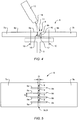
- Figure 4 shows the structural arrangement 6 after manufacturing thereof with the at least one first fiber reinforced polymer component 7a and the at least one second fiber reinforced polymer component 7b that are spaced apart from each other by the interspace 11 and that are rigidly attached to the associated structural component 8, wherein the at least one first fiber reinforced polymer component 7a and the at least one second fiber reinforced polymer component 7b are at least partly interconnected by means of the electrically conductive connection 9, which comprises the at least one sprayed layer 15 of electrically conductive particles 14.
- the at least one sprayed layer 15 of electrically conductive particles 14 is provided in the interspace 11.
- Figure 5 shows the structural arrangement 6 of Figure 4 , which exemplarily comprises a plurality of electrically conductive connections 9.
- electrically conductive connections 9 are provided, wherein adjacent ones thereof are preferably spaced apart from each other by an associated spacing S that is defined according to a necessary protection for respectively installed equipment.
- Figure 6 shows the structural arrangement 6 of Figure 2 in the preliminary process step according to Figure 2 .
- the Z-shaped first electrically conductive foil 9a is now shorter such that it cannot be arranged at least partly between the at least one second fiber reinforced polymer component 7b and the associated structural component 8 of Figure 2 .
- Figure 7 shows the structural arrangement 6 of Figure 2 in the preliminary process step according to Figure 2 .
- the first electrically conductive foil 9a is now also L- or C-shaped.
- the associated structural component 8 of Figure 2 is preferably provided with a third electrically conductive foil 9c that is preferentially electro-conductively connected to the L- or C-shaped first and second electrically conductive foils 9a, 9b.
- the third electrically conductive foil 9c is at least approximately plate-shaped and implemented by means of a metal foil, preferably a copper foil.
- Figure 8 shows the structural arrangement 6 of Figure 2 in the preliminary process step according to Figure 2 .
- the at least one first fiber reinforced polymer component 7a is now also Z-shaped and comprises an extension 8a that is at least partly arranged - in Figure 8 below - the at least one second fiber reinforced polymer component 7b.
- the at least one first fiber reinforced polymer component 7a according to Figure 6 or Figure 7 may be provided with the extension of Figure 8 , and so on.
Landscapes
- Engineering & Computer Science (AREA)
- Mechanical Engineering (AREA)
- Chemical & Material Sciences (AREA)
- Aviation & Aerospace Engineering (AREA)
- Chemical Kinetics & Catalysis (AREA)
- Materials Engineering (AREA)
- Metallurgy (AREA)
- Organic Chemistry (AREA)
- Life Sciences & Earth Sciences (AREA)
- Wood Science & Technology (AREA)
- Laminated Bodies (AREA)
Abstract
Description
- The invention is related to a structural arrangement with at least one first fiber reinforced polymer component and at least one second fiber reinforced polymer component that are spaced apart from each other by an interspace and that are rigidly attached to an associated structural component, wherein the at least one first fiber reinforced polymer component and the at least one second fiber reinforced polymer component are at least partly interconnected by means of an electrically conductive connection. The invention is further related to a method of manufacturing such a structural arrangement, as well as to a rotary wing aircraft that comprises such a structural arrangement.
- Currently, an ever increasing number of rotary wing aircrafts is authorized to fly under Instrument Flight Rules (IFR) in all type of weather conditions, so that operating environments of such rotary wing aircrafts and, consequently, an underlying design philosophy have significantly changed. This particularly applies to respective structural arrangements, especially aircraft airframes resp. fuselages, of the rotary wing aircrafts, which are more and more implemented by means of fiber reinforced polymer components, e. g. fiber reinforced polymer panels.
- However, such fiber reinforced polymer components have an electrical behavior, in particular with respect to lightning strikes, that significantly differs from a respective electrical behavior of e. g. Aluminum structural arrangements, which were formerly mainly used in implementing aircraft structural arrangements. As a result of this different electrical behavior, a respective possibility of a lightning strike of a given rotary wing aircraft has increased.
- As it is well-known, such a lightning strike may have serious consequences. Such consequences are roughly divided into two different categories: lightning direct effects (LDEs) and lightning indirect effects (LIEs).
- More specifically, LDEs refer to damages that include burning, eroding, blasting and structural deformation produced by high electrical currents resulting from a lightning flash that passes through a structural arrangement of a given rotary wing aircraft. LIEs in turn refer to perturbations, failures, damages of equipment, including ignitions, which result from a respective electrical transient that is generated by a lightning flash and that leads to an electromagnetic coupling with electrical and/or electronical equipment of a given rotary wing aircraft.
- In summary, as rotary wing aircrafts that are mainly implemented by means of fiber reinforced polymer components, e. g. fiber reinforced polymer panels, are comparatively more prone to lightning strikes, they must be provided with a suitable protection against LDEs and LIEs. For instance, as such fiber reinforced polymer components, e. g. carbon fiber reinforced polymer components, have a higher electrical resistance than comparable Aluminum components, a proper metallization for electrical bonding and grounding is necessary. Furthermore, with respect to LIEs such fiber reinforced polymer components must be electrically connected to each other at a predefined distance depending on the installed equipment with a maximum resistance of e. g. 1 mΩ.
- Conventionally, an electrical connection of fiber reinforced polymer components is performed by means of copper splices that are mounted to the fiber reinforced polymer components by means of an electrically conductive adhesive and riveting. This is either performed directly on top of the fiber reinforced polymer components, or in respective recesses provided thereon. By way of example, such electrical connections are described in the documents
US 2010/0320325 A1 ,US 2005/0213278 A1 ,US 4,888,451 A andWO 2005/032812 A2 . - However, such conventionally realized electrical connections are usually comparatively costly, e. g. due to a required provision of respective recesses and/or additionally required components. They may also be disadvantageous regarding an undesired increase of a respective aerodynamic resistance of outer surfaces of aircraft structural arrangements.
- It is, therefore, an object of the present invention to provide a new rotary wing aircraft with a structural arrangement that comprises at least one first fiber reinforced polymer component and at least one second fiber reinforced polymer component with at least one improved electrical connection between the first and second fiber reinforced polymer components. It is a further object of the present invention to provide a method of manufacturing such a structural arrangement and it is, moreover, an object of the present invention to provide such a structural arrangement as such.
- This object is solved by a structural arrangement with at least one first fiber reinforced polymer component and at least one second fiber reinforced polymer component, the structural arrangement comprising the features of claim 1.
- More specifically, according to the present invention the structural arrangement comprises at least one first fiber reinforced polymer component and at least one second fiber reinforced polymer component that are spaced apart from each other by an interspace and that are rigidly attached to an associated structural component. The at least one first fiber reinforced polymer component and the at least one second fiber reinforced polymer component are at least partly interconnected by means of an electrically conductive connection. The electrically conductive connection comprises at least one sprayed layer of electrically conductive particles that is provided in the interspace.
- According to one aspect, the at least one first and second fiber reinforced polymer components are preferably attached to structural elements of an aircraft, in particular a rotary wing aircraft, such as e. g. T-shaped stringers, ribs, beams etc. However, between the fiber reinforced polymer components that are attached to such structural elements, usually an interspace or gap is formed, which leads to an undesired and disadvantageous, comparatively high electrical resistance, which must at least be reduced and, preferably, be avoided. Even if each one of the at least one first and second fiber reinforced polymer components is provided with a respective electrically conductive foil at its selvage and an electrically conductive metal mesh on its outer surface, which is preferably made of copper, the interspace or gap that conventionally amounts to approximately 1 mm to 10mm interrupts an underlying electrical conductivity between the fiber reinforced polymer components and leads to a comparatively high electrical resistance between them.
- Therefore, fiber reinforced polymer components of structural arrangements, e. g. fiber reinforced polymer components that are used for constructing aircraft structural arrangements, especially in rotary wing aircrafts, or structural arrangements of other vehicles or machines, are according to one aspect at least partly electrically connected to each other by using a thermal gas spray technology. Preferably, each fiber reinforced polymer component therein is provided with a thin metal foil at its selvage and thin metal foils provided at selvages of adjacent fiber reinforced polymer components are electrically connected to each other. Thereby, a small slot between the thin metal foils may be created, which may lead to a reduced electrical current flow capacity between the thin metal foils and, thus, the respective adjacent fiber reinforced polymer components. Consequently, by building up a metal bridging layer respectively bridging layers at the location of the small slot between the thin metal foils by means of the thermal spray or thermal gas spray technology, at least an improved electrical connection of the thin metal foils can be achieved.
- Advantageously, by using the thermal gas spray technology, at least an improved and preferably a high and constant quality electrical connection of thin metal foils provided at adjacent fiber reinforced polymer components can be achieved. Therein, the thermal gas spray technology is preferentially implemented by means of an automated process. Thus, a significant cost reduction and important time savings can be realized, while generally obtaining a smooth outer surface of electrically connected fiber reinforced polymer components.
- More specifically, the thermal gas spray technology and, in particular, a cold gas or metal gas spray technology, is applied for finishing an electrically conductive connection between two adjacently mounted fiber reinforced polymer components in order to provide for a comparatively low electrical resistance of preferentially less than 1mΩ between these two adjacently mounted fiber reinforced polymer components.
- According to a preferred embodiment, the at least one sprayed layer of electrically conductive particles fills the interspace at least partly.
- According to a further preferred embodiment, the at least one first fiber reinforced polymer component is electro-conductively connected to a first electrically conductive foil and the at least one second fiber reinforced polymer component is electro-conductively connected to a second electrically conductive foil. The at least one sprayed layer of electrically conductive particles is at least partly formed between the first and second electrically conductive foils.
- According to a further preferred embodiment, the first and second electrically conductive foils are separated in the interspace by at least one slot, the at least one sprayed layer of electrically conductive particles being provided for bridging the at least one slot.
- According to a further preferred embodiment, the first electrically conductive foil is at least approximately L-, C- or Z-shaped.
- According to a further preferred embodiment, the second electrically conductive foil is at least approximately L- or C-shaped.
- According to a further preferred embodiment, the associated structural component is connected to a third electrically conductive foil, the third electrically conductive foil being electro-conductively connected to the first electrically conductive foil and the second electrically conductive foil.
- According to a further preferred embodiment, the third electrically conductive foil is at least approximately plate-shaped.
- According to a further preferred embodiment, the electrically conductive connection exhibits an electrical resistance of less than 1mΩ between the first electrically conductive foil and the second electrically conductive foil.
- According to a further preferred embodiment, the at least one first fiber reinforced polymer component and the at least one second fiber reinforced polymer component are rigidly attached to the associated structural component by means of associated fixation means that comprise at least one of screws, rivets, bolts and structural bonding.
- According to a further preferred embodiment, the associated structural component is one of a joggled panel, shell, stringer, rib, frame and beam of a rotary wing aircraft and the at least one first fiber reinforced polymer component and the at least one second fiber reinforced polymer component are implemented as panels or shells of the rotary wing aircraft, wherein the interspace exhibits a width that is comprised in a range between 1mm and 10mm.
- The present invention further provides a method of manufacturing a structural arrangement from at least one first fiber reinforced polymer component, at least one second fiber reinforced polymer component and an associated structural component. The method comprises:
- providing the at least one first fiber reinforced polymer component at least partly with a first electrically conductive foil and the at least one second fiber reinforced polymer component at least partly with a second electrically conductive foil;
- rigidly attaching the at least one first fiber reinforced polymer component and the at least one second fiber reinforced polymer component to the associated structural component, wherein an interspace is created that spaces the at least one first fiber reinforced polymer component and the at least one second fiber reinforced polymer component apart from each other, wherein a slot is at least partly created between the first electrically conductive foil and the second electrically conductive foil; and
- spraying electrically conductive particles in the interspace onto the slot for creating a sprayed layer of electrically conductive particles, the at least one sprayed layer of electrically conductive particles being provided for electro-conductively interconnecting at least partly the first electrically conductive foil and the second electrically conductive foil.
- According to a preferred embodiment, spraying of the electrically conductive particles is performed by means of a thermal spray technology.
- According to a further preferred embodiment, the thermal spray technology comprises a cold gas spray method.
- The present invention further provides a rotary wing aircraft with a structural arrangement as described above.
- Preferred embodiments of the invention are outlined by way of example in the following description with reference to the attached drawings. In these attached drawings, identical or identically functioning components and elements are labelled with identical reference numbers and characters and are, consequently, only described once in the following description.
-
Figure 1 shows a lateral view of a helicopter with a fuselage that comprises a structural arrangement according to the invention, -
Figure 2 to Figure 4 illustrate a method of manufacturing a structural arrangement according to one aspect, -
Figure 5 shows a top view of a structural arrangement that is manufactured according toFigure 2 to Figure 4 , and - Fig.
ure 6 toFigure 8 show alternative structural arrangements. -
Figure 1 shows an aircraft 1 that is exemplarily illustrated as a rotary wing aircraft and, more particularly, as a helicopter. Thus, for purposes of simplicity and clarity, the aircraft 1 is hereinafter referred to as the "helicopter" 1. - Illustratively, the helicopter 1 comprises a
fuselage 2 that is connected to alanding gear 1f and defines acabin 2a and arear fuselage 2b. Therear fuselage 2b is connected to atail boom 3. - According to one aspect, the
fuselage 2 comprises at least onestructural arrangement 6, or embodies thestructural arrangement 6, which is preferably implemented using at least two fiber reinforced polymer components (7a, 7b inFigure 2 ). Thestructural arrangement 6 is exemplarily and representatively described in detail below with respect toFigure 2 to Figure 8 . - Illustratively, the helicopter 1 further comprises at least one multi-blade
main rotor 1a for providing lift and forward or backward thrust during operation. The at least one multi-blademain rotor 1a comprises a plurality ofrotor blades rotor head 1 d to arotor shaft 1 e, which rotates in operation of the helicopter 1 around an associated rotor axis. - By way of example, the helicopter 1 further comprises at least one preferentially shrouded
counter-torque device 4 configured to provide counter-torque during operation, i. e. to counter the torque created by rotation of the at least one multi-blademain rotor 1a for purposes of balancing the helicopter 1 in terms of yaw. The at least onecounter-torque device 4 is illustratively provided at an aft section of thetail boom 3 and preferably comprises atail rotor 4a. The aft section of thetail boom 3 preferably further comprises avertical stabilizer 5. Illustratively, thetail boom 3 is also provided with a suitablehorizontal stabilizer 3a. - Preferably, the
tail boom 3 is a composite tail boom, i. e. a tail boom that comprises composite material and that is preferably at least essentially manufactured from composite material, preferentially fiber reinforced polymer material. Illustratively, thecomposite tail boom 3 is preferably implemented as a slim beam element that comprises at least partly atail boom cone 3b, which is preferably tubular. In other words, thecomposite tail boom 3 is preferentially a closed structure with a nearly circular cross section. -
Figure 2 shows thestructural arrangement 6 ofFigure 1 , which is implemented according to a first aspect. In connection withFigure 3 andFigure 4 ,Figure 2 illustrates an exemplary method of manufacturing thestructural arrangement 6. - The
structural arrangement 6 preferably comprises at least one first fiber reinforcedpolymer component 7a and at least one second fiber reinforcedpolymer component 7b, which are preferentially implemented as panels or shells of the helicopter 1 ofFigure 1 . The at least one first fiber reinforcedpolymer component 7a and the at least one second fiber reinforcedpolymer component 7b are preferably produced by means of a standard procedure in a preliminary process step, which includes lamination of metal meshes, preferably copper meshes 9d, 9e, on respective - inFigure 2 upper - surfaces of the at least one first fiber reinforcedpolymer component 7a and the at least one second fiber reinforcedpolymer component 7b. - The at least one first fiber reinforced
polymer component 7a and the at least one second fiber reinforcedpolymer component 7b preferably comprise carbon fiber reinforced polymers, but may alternatively comprise also other kinds of reinforcement fibers, such as glass, aramid and so on. However, the present invention is not limited to such fiber reinforced polymer components, but more generally likewise applies to any other nonconductive material. Thus, in the context of the present invention the term "fiber reinforced polymer component" is construed for designating any component of nonconductive material, comprising components made of fiber reinforced polymers. - According to one aspect, the at least one first fiber reinforced
polymer component 7a is electro-conductively connected to a first electricallyconductive foil 9a and the at least one second fiber reinforcedpolymer component 7b is electro-conductively connected to a second electricallyconductive foil 9b. The first and second electricallyconductive foils polymer component 7a and the at least one second fiber reinforcedpolymer component 7b and, thus, creating an electricallyconductive connection 9 there between. - Preferably, the first electrically
conductive foil 9a is at least approximately Z-shaped, i. e. illustratively comprises two kinks in cross section. The second electricallyconductive foil 9b is preferentially at least approximately L- or C-shaped, i. e. illustratively comprises not more than a single kink. According to one aspect, the first and second electricallyconductive foils polymer component 7a and the at least one second fiber reinforcedpolymer component 7b, respectively, at associated locations resp. edges. This is preferentially accomplished during the preliminary process step. - In a parallel process step, one or more structural components resp. connecting surfaces of such structural components for attaching the at least one first fiber reinforced
polymer component 7a and the at least one second fiber reinforcedpolymer component 7b can be prepared. Such a preparation may include bonding of a metallic foil, preferably a copper foil (9c inFigure 7 ), on respective intended attachment areas, or directly laminating the metallic foil onto the respective connection surfaces of the one or more structural components, if they are made of fiber reinforced polymers. - By way of example, an associated
structural component 8 is prepared, which is illustratively implemented as a T-shaped stringer of the helicopter 1 ofFigure 1 . However, other structural components, in particular structural components of the helicopter 1 ofFigure 1 , are likewise contemplated, such as e. g. joggled panels, shells, ribs, frames and beams. -
Figure 3 shows thestructural arrangement 6 ofFigure 2 with the at least one first fiber reinforcedpolymer component 7a, the at least one second fiber reinforcedpolymer component 7b and the associatedstructural component 8. The at least one first fiber reinforcedpolymer component 7a comprises the Z-shaped first electricallyconductive foil 9a and the at least one second fiber reinforcedpolymer component 7b comprises the L- or C-shaped second electricallyconductive foil 9b. - According to one aspect, the at least one first fiber reinforced
polymer component 7a and the at least one second fiber reinforcedpolymer component 7b are spaced apart from each other by aninterspace 11 and rigidly attached to the associatedstructural component 8 in an associated assembling process step. Theinterspace 11 exhibits a width D that is preferentially comprised in a range between 1 mm and 10mm. The rigid attachment is preferably performed by means of associated fixation means 10 that comprise at least one of screws, rivets, bolts and structural bonding. - Illustratively, the at least one first fiber reinforced
polymer component 7a and the at least one second fiber reinforcedpolymer component 7b are rigidly attached to the associatedstructural component 8 such that at least a portion of the Z-shaped first electricallyconductive foil 9a is arranged between the at least one second fiber reinforcedpolymer component 7b and the associatedstructural component 8. However, as a result of this rigid attachment, the Z-shaped first and L- or C-shaped second electricallyconductive foils interspace 11 by at least one slot orrecess 12. This at least one slot orrecess 12, however, interrupts an underling electrical conductivity between the Z-shaped first and L- or C-shaped second electricallyconductive foils -
Figure 4 shows thestructural arrangement 6 ofFigure 3 with the at least one first fiber reinforcedpolymer component 7a and the at least one second fiber reinforcedpolymer component 7b, which are rigidly attached to the associatedstructural component 8. The at least one first fiber reinforcedpolymer component 7a comprises the Z-shaped first electricallyconductive foil 9a and the at least one second fiber reinforcedpolymer component 7b comprises the L- or C-shaped second electricallyconductive foil 9b, which are provided for creating the electricallyconductive connection 9 and which are at least partly separated in theinterspace 11 by the at least one slot orrecess 12. - According to one aspect, the at least one slot or
recess 12 is bridged in an associated bridging process step such that the electricallyconductive connection 9 exhibits an electrical resistance of less than 1mΩ between the Z-shaped first electricallyconductive foil 9a and the L- or C-shaped second electricallyconductive foil 9b. During this associated bridging process step, preferably at least one sprayedlayer 15 of electricallyconductive particles 14 is provided, i. e. created in theinterspace 11 for bridging the at least one slot orrecess 12. Preferentially, the at least one sprayedlayer 15 of electricallyconductive particles 14 is at least partly formed between the Z-shaped first electricallyconductive foil 9a and the L- or C-shaped second electricallyconductive foil 9b. - According to one aspect, the at least one sprayed
layer 15 of electricallyconductive particles 14 is created resp. formed by spraying, in particular thermal spraying of the electricallyconductive particles 14 onto the at least one slot orrecess 12 by means of a thermal spray technology using asuitable spraying tool 13. Preferentially, the thermal spray technology is realized as a metal gas or cold gas spray method. - The thermal spraying is preferably done by a robot in an automatized process for series production, while repairing of the electrically
conductive connection 9 and, more specifically, the at least one sprayedlayer 15 could be done manually. This guaranties low production costs and a high quality of the at least one sprayedlayer 15. - However, it should be noted that the thermal spraying is not limited to the above described metal gas or cold gas spray method which is one of many different thermal spray methods that can likewise be applied. It should further be noted that thermal spraying, i. e. the thermal spray technology, as such is not part of the present invention and well-known to the person skilled in the art and, therefore, not described in more detail hereinafter.
- Preferably, the at least one sprayed
layer 15 of electricallyconductive particles 14 fills theinterspace 11 at least partly. Illustratively, but not necessarily, the at least one sprayedlayer 15 leaves a remainingempty interspace 16 in theinterspace 11. This remainingempty interspace 16 is preferably filled with a corrosion resistant filler material to smoothen out an outer - inFigure 4 upper - surface of thestructural arrangement 6, e. g. prior to a final painting process step thereof. - In summary,
Figure 4 shows thestructural arrangement 6 after manufacturing thereof with the at least one first fiber reinforcedpolymer component 7a and the at least one second fiber reinforcedpolymer component 7b that are spaced apart from each other by theinterspace 11 and that are rigidly attached to the associatedstructural component 8, wherein the at least one first fiber reinforcedpolymer component 7a and the at least one second fiber reinforcedpolymer component 7b are at least partly interconnected by means of the electricallyconductive connection 9, which comprises the at least one sprayedlayer 15 of electricallyconductive particles 14. As described above, the at least one sprayedlayer 15 of electricallyconductive particles 14 is provided in theinterspace 11. -
Figure 5 shows thestructural arrangement 6 ofFigure 4 , which exemplarily comprises a plurality of electricallyconductive connections 9. Illustratively, four electricallyconductive connections 9 are provided, wherein adjacent ones thereof are preferably spaced apart from each other by an associated spacing S that is defined according to a necessary protection for respectively installed equipment. - However, it should be noted that the
structural arrangement 6 is represented in a simplified manner inFigure 5 for simplicity and clarity of the drawings. For instance, the electricallyconductive surfaces Figure 4 are not shown, and so on. -
Figure 6 shows thestructural arrangement 6 ofFigure 2 in the preliminary process step according toFigure 2 . However, in contrast toFigure 2 , the Z-shaped first electricallyconductive foil 9a is now shorter such that it cannot be arranged at least partly between the at least one second fiber reinforcedpolymer component 7b and the associatedstructural component 8 ofFigure 2 . -
Figure 7 shows thestructural arrangement 6 ofFigure 2 in the preliminary process step according toFigure 2 . However, in contrast toFigure 2 , the first electricallyconductive foil 9a is now also L- or C-shaped. In this case, the associatedstructural component 8 ofFigure 2 is preferably provided with a third electricallyconductive foil 9c that is preferentially electro-conductively connected to the L- or C-shaped first and second electricallyconductive foils conductive foil 9c is at least approximately plate-shaped and implemented by means of a metal foil, preferably a copper foil. - However, it should be noted that in this case at least two recesses or slots are created in the
interspace 11, one between the L- or C-shaped first electricallyconductive foil 9a and the plate-shaped third electricallyconductive foil 9c, and another one between the L- or C-shaped second electricallyconductive foil 9b and the plate-shaped third electricallyconductive foil 9c. Consequently, at least two sprayed layers according to the sprayedlayer 15 ofFigure 4 must be created. -
Figure 8 shows thestructural arrangement 6 ofFigure 2 in the preliminary process step according toFigure 2 . However, in contrast toFigure 2 , the at least one first fiber reinforcedpolymer component 7a is now also Z-shaped and comprises anextension 8a that is at least partly arranged - inFigure 8 below - the at least one second fiber reinforcedpolymer component 7b. - It should be noted that modifications to the above described embodiments are within the common knowledge of the person skilled in the art and, thus, also considered as being part of the present invention. For instance, the at least one first fiber reinforced
polymer component 7a according toFigure 6 or Figure 7 may be provided with the extension ofFigure 8 , and so on. -
- 1
- rotary wing aircraft
- 1a
- multi-blade main rotor
- 1b, 1c
- rotor blades
- 1 d
- rotor head
- 1e
- rotor shaft
- 1f
- landing gear
- 2
- fuselage
- 2a
- cabin
- 2b
- rear fuselage
- 3
- tail boom
- 3a
- horizontal stabilizer
- 3b
- tail boom cone
- 4
- counter-torque device
- 4a
- tail rotor
- 5
- vertical stabilizer
- 6
- structural arrangement
- 7a, 7b
- nonconductive material
- 8
- aircraft structural component
- 8a
- material extension
- 9
- electrically conductive connection
- 9a
- electrically conductive L- or Z-shaped foil
- 9b
- electrically conductive L- or C-shaped foil
- 9c
- electrically conductive plate-shaped foil
- 9d, 9e
- electrically conductive surfaces
- 10
- fixation means
- 11
- fiber reinforced polymer component interspace
- 12
- slot between conductive materials
- 13
- spraying tool
- 14
- electrically conductive particles
- 15
- sprayed layer of electrically conductive particles
- 16
- remaining empty interspace
- D
- fiber reinforced polymer component interspace width
- S
- electrically conductive foil spacing
Claims (15)
- A structural arrangement (6) with at least one first fiber reinforced polymer component (7a) and at least one second fiber reinforced polymer component (7b) that are spaced apart from each other by an interspace (11) and that are rigidly attached to an associated structural component (8), wherein the at least one first fiber reinforced polymer component (7a) and the at least one second fiber reinforced polymer component (7b) are at least partly interconnected by means of an electrically conductive connection (9), characterized in that the electrically conductive connection (9) comprises at least one sprayed layer (15) of electrically conductive particles (14), the at least one sprayed layer (15) of electrically conductive particles (14) being provided in the interspace (11).
- The structural arrangement (6) of claim 1,
characterized in that the at least one sprayed layer (15) of electrically conductive particles (14) fills the interspace (11) at least partly. - The structural arrangement (6) of claim 1,
characterized in that the at least one first fiber reinforced polymer component (7a) is electro-conductively connected to a first electrically conductive foil (9a) and the at least one second fiber reinforced polymer component (7b) is electro-conductively connected to a second electrically conductive foil (9b), wherein the at least one sprayed layer (15) of electrically conductive particles (14) is at least partly formed between the first and second electrically conductive foils (9a, 9b). - The structural arrangement (6) of claim 3,
characterized in that the first and second electrically conductive foils (9a, 9b) are separated in the interspace (11) by at least one slot (12), the at least one sprayed layer (15) of electrically conductive particles (14) being provided for bridging the at least one slot (12). - The structural arrangement (6) of claim 3,
characterized in that the first electrically conductive foil (9a) is at least approximately L-, C- or Z-shaped. - The structural arrangement (6) of claim 5,
characterized in that the second electrically conductive foil (9b) is at least approximately L- or C-shaped. - The structural arrangement (6) of claim 6,
characterized in that the associated structural component (8) is connected to a third electrically conductive foil (9c), the third electrically conductive foil (9c) being electro-conductively connected to the first electrically conductive foil (9a) and the second electrically conductive foil (9b). - The structural arrangement (6) of claim 7,
characterized in that the third electrically conductive foil (9c) is at least approximately plate-shaped. - The structural arrangement (6) of claim 3,
characterized in that the electrically conductive connection (9) exhibits an electrical resistance of less than 1mΩ between the first electrically conductive foil (9a) and the second electrically conductive foil (9b). - The structural arrangement (6) of claim 1,
characterized in that the at least one first fiber reinforced polymer component (7a) and the at least one second fiber reinforced polymer component (7b) are rigidly attached to the associated structural component (8) by means of associated fixation means (10) that comprise at least one of screws, rivets, bolts and structural bonding. - The structural arrangement (6) of claim 1,
characterized in that the associated structural component (8) is one of a joggled panel, shell, stringer, rib, frame and beam of a rotary wing aircraft (1) and that the at least one first fiber reinforced polymer component (7a) and the at least one second fiber reinforced polymer component (7b) are implemented as panels or shells of the rotary wing aircraft (1), wherein the interspace (11) exhibits a width that is comprised in a range between 1mm and 10mm. - A method of manufacturing a structural arrangement (6) from at least one first fiber reinforced polymer component (7a), at least one second fiber reinforced polymer component (7b) and an associated structural component (8), the method comprising:- providing the at least one first fiber reinforced polymer component (7a) at least partly with a first electrically conductive foil (9a) and the at least one second fiber reinforced polymer component (7b) at least partly with a second electrically conductive foil (9b);- rigidly attaching the at least one first fiber reinforced polymer component (7a) and the at least one second fiber reinforced polymer component (7b) to the associated structural component (8), wherein an interspace (11) is created that spaces the at least one first fiber reinforced polymer component (7a) and the at least one second fiber reinforced polymer component (7b) apart from each other, wherein a slot (12) is at least partly created between the first electrically conductive foil (9a) and the second electrically conductive foil (9b); and- spraying electrically conductive particles (14) in the interspace (11) onto the slot (12) for creating a sprayed layer (15) of electrically conductive particles (14), the at least one sprayed layer (15) of electrically conductive particles (14) being provided for electro-conductively interconnecting at least partly the first electrically conductive foil (9a) and the second electrically conductive foil (9b).
- The method of claim 12,
characterized in that spraying of the electrically conductive particles (14) is performed by means of a thermal spray technology. - The method of claim 13,
characterized in that the thermal spray technology comprises a cold gas spray method. - A rotary wing aircraft (1) with a structural arrangement (6) according to one of claims 1 to 11.
Priority Applications (2)
| Application Number | Priority Date | Filing Date | Title |
|---|---|---|---|
| EP16400043.2A EP3299297B1 (en) | 2016-09-27 | 2016-09-27 | A rotary wing aircraft with a structural arrangement that comprises an electrically conductive connection |
| US15/716,635 US10507491B2 (en) | 2016-09-27 | 2017-09-27 | Rotary wing aircraft with a structural arrangement that comprises an electrically conductive connection |
Applications Claiming Priority (1)
| Application Number | Priority Date | Filing Date | Title |
|---|---|---|---|
| EP16400043.2A EP3299297B1 (en) | 2016-09-27 | 2016-09-27 | A rotary wing aircraft with a structural arrangement that comprises an electrically conductive connection |
Publications (2)
| Publication Number | Publication Date |
|---|---|
| EP3299297A1 true EP3299297A1 (en) | 2018-03-28 |
| EP3299297B1 EP3299297B1 (en) | 2018-12-12 |
Family
ID=57218844
Family Applications (1)
| Application Number | Title | Priority Date | Filing Date |
|---|---|---|---|
| EP16400043.2A Active EP3299297B1 (en) | 2016-09-27 | 2016-09-27 | A rotary wing aircraft with a structural arrangement that comprises an electrically conductive connection |
Country Status (2)
| Country | Link |
|---|---|
| US (1) | US10507491B2 (en) |
| EP (1) | EP3299297B1 (en) |
Families Citing this family (1)
| Publication number | Priority date | Publication date | Assignee | Title |
|---|---|---|---|---|
| EP3281861B1 (en) * | 2016-08-11 | 2019-10-02 | AIRBUS HELICOPTERS DEUTSCHLAND GmbH | A rotary wing aircraft with a fuselage that comprises at least one structural stiffened panel |
Citations (8)
| Publication number | Priority date | Publication date | Assignee | Title |
|---|---|---|---|---|
| US4888451A (en) | 1988-11-29 | 1989-12-19 | United Technologies Corporation | Electrical continuity means for composite joints |
| US6245696B1 (en) * | 1999-06-25 | 2001-06-12 | Honeywell International Inc. | Lasable bond-ply materials for high density printed wiring boards |
| WO2005032812A2 (en) | 2003-09-30 | 2005-04-14 | The Boeing Company | Applique |
| US20050213278A1 (en) | 2004-03-23 | 2005-09-29 | Hawley Arthur V | Lightning damage protection for composite aircraft |
| US20100263898A1 (en) * | 2009-04-17 | 2010-10-21 | 3M Innovative Properties Company | Lightning protection sheet with patterned conductor |
| US20100320325A1 (en) | 2009-06-22 | 2010-12-23 | The Boeing Company | Skin Panel Joint for Improved Airflow |
| US20110297315A1 (en) * | 2009-02-23 | 2011-12-08 | Tomone Kishida | Method for producing resin-based composite |
| US20160107739A1 (en) * | 2012-04-19 | 2016-04-21 | Cytec Technology Corp. | Composite Materials |
Family Cites Families (2)
| Publication number | Priority date | Publication date | Assignee | Title |
|---|---|---|---|---|
| US9643734B2 (en) * | 2013-03-18 | 2017-05-09 | The Boeing Company | Electromagnetic energy surface protection |
| US10343791B2 (en) * | 2016-08-16 | 2019-07-09 | The Boeing Company | Integrated current return network in composite structures |
-
2016
- 2016-09-27 EP EP16400043.2A patent/EP3299297B1/en active Active
-
2017
- 2017-09-27 US US15/716,635 patent/US10507491B2/en active Active
Patent Citations (8)
| Publication number | Priority date | Publication date | Assignee | Title |
|---|---|---|---|---|
| US4888451A (en) | 1988-11-29 | 1989-12-19 | United Technologies Corporation | Electrical continuity means for composite joints |
| US6245696B1 (en) * | 1999-06-25 | 2001-06-12 | Honeywell International Inc. | Lasable bond-ply materials for high density printed wiring boards |
| WO2005032812A2 (en) | 2003-09-30 | 2005-04-14 | The Boeing Company | Applique |
| US20050213278A1 (en) | 2004-03-23 | 2005-09-29 | Hawley Arthur V | Lightning damage protection for composite aircraft |
| US20110297315A1 (en) * | 2009-02-23 | 2011-12-08 | Tomone Kishida | Method for producing resin-based composite |
| US20100263898A1 (en) * | 2009-04-17 | 2010-10-21 | 3M Innovative Properties Company | Lightning protection sheet with patterned conductor |
| US20100320325A1 (en) | 2009-06-22 | 2010-12-23 | The Boeing Company | Skin Panel Joint for Improved Airflow |
| US20160107739A1 (en) * | 2012-04-19 | 2016-04-21 | Cytec Technology Corp. | Composite Materials |
Also Published As
| Publication number | Publication date |
|---|---|
| US10507491B2 (en) | 2019-12-17 |
| US20180085782A1 (en) | 2018-03-29 |
| EP3299297B1 (en) | 2018-12-12 |
Similar Documents
| Publication | Publication Date | Title |
|---|---|---|
| US11629411B2 (en) | Structural arrangement with a fiber reinforced polymer component and a cold gas sprayed electrically conductive layer | |
| EP3153410B1 (en) | Methods for diverting lightning current from skin fasteners in composite, non-metallic structures | |
| EP2130762B1 (en) | Wing and empennage leading edge structure made of thermoplastic material with a stiffened double-shell configuration | |
| US8699203B2 (en) | System for dissipating a lightning current generated by a thunderstorm discharge on an aircraft | |
| EP3318481B1 (en) | Panel structure for an aircraft and manufacturing method thereof | |
| US20170210458A1 (en) | Aircraft frame structure and associated method | |
| EP2716544B1 (en) | Horizontal airfoil tip fairing | |
| EP3501994B1 (en) | Aircraft and method for producing an aircraft | |
| EP2125509B1 (en) | Fuselage of an aircraft or spacecraft of crp/metal hybrid construction with a metal framework | |
| KR20180022609A (en) | Wing and method of manufacturing | |
| EP3083231B1 (en) | Composite structure | |
| EP3156321B1 (en) | Composite stiffener with integral conductive element | |
| US10329030B2 (en) | Conductive radius filler system and method | |
| US20110233338A1 (en) | Joint | |
| EP1549545B1 (en) | Lightning strike protection and grounding of a composite aircraft panel | |
| US10953624B2 (en) | Aircraft airfoil having a stitched trailing edge and manufacturing method thereof | |
| JP2011051517A (en) | Aircraft wing | |
| EP2987562B1 (en) | Methods and apparatus for use in forming a lightning protection system | |
| US10507491B2 (en) | Rotary wing aircraft with a structural arrangement that comprises an electrically conductive connection | |
| EP3597527A1 (en) | Pressure bulkhead and method of installation | |
| EP4302987A1 (en) | Structure with lightning-strike protection layer | |
| EP4685048A1 (en) | A structural panel with carbon composite plies | |
| EP3173328B1 (en) | Leading edge with laminar flow control | |
| EP4257480A1 (en) | Wing-box structure | |
| EP4200203A1 (en) | A cover panel |
Legal Events
| Date | Code | Title | Description |
|---|---|---|---|
| PUAI | Public reference made under article 153(3) epc to a published international application that has entered the european phase |
Free format text: ORIGINAL CODE: 0009012 |
|
| STAA | Information on the status of an ep patent application or granted ep patent |
Free format text: STATUS: THE APPLICATION HAS BEEN PUBLISHED |
|
| STAA | Information on the status of an ep patent application or granted ep patent |
Free format text: STATUS: REQUEST FOR EXAMINATION WAS MADE |
|
| AK | Designated contracting states |
Kind code of ref document: A1 Designated state(s): AL AT BE BG CH CY CZ DE DK EE ES FI FR GB GR HR HU IE IS IT LI LT LU LV MC MK MT NL NO PL PT RO RS SE SI SK SM TR |
|
| AX | Request for extension of the european patent |
Extension state: BA ME |
|
| 17P | Request for examination filed |
Effective date: 20180316 |
|
| RBV | Designated contracting states (corrected) |
Designated state(s): AL AT BE BG CH CY CZ DE DK EE ES FI FR GB GR HR HU IE IS IT LI LT LU LV MC MK MT NL NO PL PT RO RS SE SI SK SM TR |
|
| GRAP | Despatch of communication of intention to grant a patent |
Free format text: ORIGINAL CODE: EPIDOSNIGR1 |
|
| STAA | Information on the status of an ep patent application or granted ep patent |
Free format text: STATUS: GRANT OF PATENT IS INTENDED |
|
| RIC1 | Information provided on ipc code assigned before grant |
Ipc: B05D 5/12 20060101ALI20180704BHEP Ipc: B05D 7/02 20060101ALI20180704BHEP Ipc: B64C 1/12 20060101ALI20180704BHEP Ipc: C23C 24/04 20060101ALI20180704BHEP Ipc: B64D 45/02 20060101AFI20180704BHEP Ipc: B29C 65/56 20060101ALI20180704BHEP Ipc: H01R 4/64 20060101ALI20180704BHEP Ipc: B29C 65/00 20060101ALI20180704BHEP Ipc: B05D 1/02 20060101ALI20180704BHEP Ipc: B29L 31/30 20060101ALI20180704BHEP |
|
| INTG | Intention to grant announced |
Effective date: 20180807 |
|
| GRAS | Grant fee paid |
Free format text: ORIGINAL CODE: EPIDOSNIGR3 |
|
| GRAA | (expected) grant |
Free format text: ORIGINAL CODE: 0009210 |
|
| STAA | Information on the status of an ep patent application or granted ep patent |
Free format text: STATUS: THE PATENT HAS BEEN GRANTED |
|
| AK | Designated contracting states |
Kind code of ref document: B1 Designated state(s): AL AT BE BG CH CY CZ DE DK EE ES FI FR GB GR HR HU IE IS IT LI LT LU LV MC MK MT NL NO PL PT RO RS SE SI SK SM TR |
|
| REG | Reference to a national code |
Ref country code: GB Ref legal event code: FG4D |
|
| REG | Reference to a national code |
Ref country code: CH Ref legal event code: EP |
|
| REG | Reference to a national code |
Ref country code: AT Ref legal event code: REF Ref document number: 1075652 Country of ref document: AT Kind code of ref document: T Effective date: 20181215 |
|
| REG | Reference to a national code |
Ref country code: DE Ref legal event code: R096 Ref document number: 602016008142 Country of ref document: DE |
|
| REG | Reference to a national code |
Ref country code: IE Ref legal event code: FG4D |
|
| REG | Reference to a national code |
Ref country code: NL Ref legal event code: MP Effective date: 20181212 |
|
| REG | Reference to a national code |
Ref country code: LT Ref legal event code: MG4D |
|
| PG25 | Lapsed in a contracting state [announced via postgrant information from national office to epo] |
Ref country code: LT Free format text: LAPSE BECAUSE OF FAILURE TO SUBMIT A TRANSLATION OF THE DESCRIPTION OR TO PAY THE FEE WITHIN THE PRESCRIBED TIME-LIMIT Effective date: 20181212 Ref country code: NO Free format text: LAPSE BECAUSE OF FAILURE TO SUBMIT A TRANSLATION OF THE DESCRIPTION OR TO PAY THE FEE WITHIN THE PRESCRIBED TIME-LIMIT Effective date: 20190312 Ref country code: HR Free format text: LAPSE BECAUSE OF FAILURE TO SUBMIT A TRANSLATION OF THE DESCRIPTION OR TO PAY THE FEE WITHIN THE PRESCRIBED TIME-LIMIT Effective date: 20181212 Ref country code: LV Free format text: LAPSE BECAUSE OF FAILURE TO SUBMIT A TRANSLATION OF THE DESCRIPTION OR TO PAY THE FEE WITHIN THE PRESCRIBED TIME-LIMIT Effective date: 20181212 Ref country code: BG Free format text: LAPSE BECAUSE OF FAILURE TO SUBMIT A TRANSLATION OF THE DESCRIPTION OR TO PAY THE FEE WITHIN THE PRESCRIBED TIME-LIMIT Effective date: 20190312 Ref country code: ES Free format text: LAPSE BECAUSE OF FAILURE TO SUBMIT A TRANSLATION OF THE DESCRIPTION OR TO PAY THE FEE WITHIN THE PRESCRIBED TIME-LIMIT Effective date: 20181212 Ref country code: FI Free format text: LAPSE BECAUSE OF FAILURE TO SUBMIT A TRANSLATION OF THE DESCRIPTION OR TO PAY THE FEE WITHIN THE PRESCRIBED TIME-LIMIT Effective date: 20181212 |
|
| REG | Reference to a national code |
Ref country code: AT Ref legal event code: MK05 Ref document number: 1075652 Country of ref document: AT Kind code of ref document: T Effective date: 20181212 |
|
| PG25 | Lapsed in a contracting state [announced via postgrant information from national office to epo] |
Ref country code: GR Free format text: LAPSE BECAUSE OF FAILURE TO SUBMIT A TRANSLATION OF THE DESCRIPTION OR TO PAY THE FEE WITHIN THE PRESCRIBED TIME-LIMIT Effective date: 20190313 Ref country code: RS Free format text: LAPSE BECAUSE OF FAILURE TO SUBMIT A TRANSLATION OF THE DESCRIPTION OR TO PAY THE FEE WITHIN THE PRESCRIBED TIME-LIMIT Effective date: 20181212 Ref country code: AL Free format text: LAPSE BECAUSE OF FAILURE TO SUBMIT A TRANSLATION OF THE DESCRIPTION OR TO PAY THE FEE WITHIN THE PRESCRIBED TIME-LIMIT Effective date: 20181212 Ref country code: SE Free format text: LAPSE BECAUSE OF FAILURE TO SUBMIT A TRANSLATION OF THE DESCRIPTION OR TO PAY THE FEE WITHIN THE PRESCRIBED TIME-LIMIT Effective date: 20181212 |
|
| PG25 | Lapsed in a contracting state [announced via postgrant information from national office to epo] |
Ref country code: NL Free format text: LAPSE BECAUSE OF FAILURE TO SUBMIT A TRANSLATION OF THE DESCRIPTION OR TO PAY THE FEE WITHIN THE PRESCRIBED TIME-LIMIT Effective date: 20181212 |
|
| PG25 | Lapsed in a contracting state [announced via postgrant information from national office to epo] |
Ref country code: PL Free format text: LAPSE BECAUSE OF FAILURE TO SUBMIT A TRANSLATION OF THE DESCRIPTION OR TO PAY THE FEE WITHIN THE PRESCRIBED TIME-LIMIT Effective date: 20181212 Ref country code: IT Free format text: LAPSE BECAUSE OF FAILURE TO SUBMIT A TRANSLATION OF THE DESCRIPTION OR TO PAY THE FEE WITHIN THE PRESCRIBED TIME-LIMIT Effective date: 20181212 Ref country code: PT Free format text: LAPSE BECAUSE OF FAILURE TO SUBMIT A TRANSLATION OF THE DESCRIPTION OR TO PAY THE FEE WITHIN THE PRESCRIBED TIME-LIMIT Effective date: 20190412 Ref country code: CZ Free format text: LAPSE BECAUSE OF FAILURE TO SUBMIT A TRANSLATION OF THE DESCRIPTION OR TO PAY THE FEE WITHIN THE PRESCRIBED TIME-LIMIT Effective date: 20181212 |
|
| PG25 | Lapsed in a contracting state [announced via postgrant information from national office to epo] |
Ref country code: SM Free format text: LAPSE BECAUSE OF FAILURE TO SUBMIT A TRANSLATION OF THE DESCRIPTION OR TO PAY THE FEE WITHIN THE PRESCRIBED TIME-LIMIT Effective date: 20181212 Ref country code: EE Free format text: LAPSE BECAUSE OF FAILURE TO SUBMIT A TRANSLATION OF THE DESCRIPTION OR TO PAY THE FEE WITHIN THE PRESCRIBED TIME-LIMIT Effective date: 20181212 Ref country code: IS Free format text: LAPSE BECAUSE OF FAILURE TO SUBMIT A TRANSLATION OF THE DESCRIPTION OR TO PAY THE FEE WITHIN THE PRESCRIBED TIME-LIMIT Effective date: 20190412 Ref country code: RO Free format text: LAPSE BECAUSE OF FAILURE TO SUBMIT A TRANSLATION OF THE DESCRIPTION OR TO PAY THE FEE WITHIN THE PRESCRIBED TIME-LIMIT Effective date: 20181212 Ref country code: SK Free format text: LAPSE BECAUSE OF FAILURE TO SUBMIT A TRANSLATION OF THE DESCRIPTION OR TO PAY THE FEE WITHIN THE PRESCRIBED TIME-LIMIT Effective date: 20181212 |
|
| REG | Reference to a national code |
Ref country code: DE Ref legal event code: R097 Ref document number: 602016008142 Country of ref document: DE |
|
| PLBE | No opposition filed within time limit |
Free format text: ORIGINAL CODE: 0009261 |
|
| STAA | Information on the status of an ep patent application or granted ep patent |
Free format text: STATUS: NO OPPOSITION FILED WITHIN TIME LIMIT |
|
| PG25 | Lapsed in a contracting state [announced via postgrant information from national office to epo] |
Ref country code: DK Free format text: LAPSE BECAUSE OF FAILURE TO SUBMIT A TRANSLATION OF THE DESCRIPTION OR TO PAY THE FEE WITHIN THE PRESCRIBED TIME-LIMIT Effective date: 20181212 Ref country code: AT Free format text: LAPSE BECAUSE OF FAILURE TO SUBMIT A TRANSLATION OF THE DESCRIPTION OR TO PAY THE FEE WITHIN THE PRESCRIBED TIME-LIMIT Effective date: 20181212 |
|
| 26N | No opposition filed |
Effective date: 20190913 |
|
| PG25 | Lapsed in a contracting state [announced via postgrant information from national office to epo] |
Ref country code: TR Free format text: LAPSE BECAUSE OF FAILURE TO SUBMIT A TRANSLATION OF THE DESCRIPTION OR TO PAY THE FEE WITHIN THE PRESCRIBED TIME-LIMIT Effective date: 20181212 |
|
| PG25 | Lapsed in a contracting state [announced via postgrant information from national office to epo] |
Ref country code: MC Free format text: LAPSE BECAUSE OF FAILURE TO SUBMIT A TRANSLATION OF THE DESCRIPTION OR TO PAY THE FEE WITHIN THE PRESCRIBED TIME-LIMIT Effective date: 20181212 |
|
| REG | Reference to a national code |
Ref country code: CH Ref legal event code: PL |
|
| PG25 | Lapsed in a contracting state [announced via postgrant information from national office to epo] |
Ref country code: CH Free format text: LAPSE BECAUSE OF NON-PAYMENT OF DUE FEES Effective date: 20190930 Ref country code: LU Free format text: LAPSE BECAUSE OF NON-PAYMENT OF DUE FEES Effective date: 20190927 Ref country code: LI Free format text: LAPSE BECAUSE OF NON-PAYMENT OF DUE FEES Effective date: 20190930 Ref country code: IE Free format text: LAPSE BECAUSE OF NON-PAYMENT OF DUE FEES Effective date: 20190927 |
|
| REG | Reference to a national code |
Ref country code: BE Ref legal event code: MM Effective date: 20190930 |
|
| PG25 | Lapsed in a contracting state [announced via postgrant information from national office to epo] |
Ref country code: BE Free format text: LAPSE BECAUSE OF NON-PAYMENT OF DUE FEES Effective date: 20190930 |
|
| PG25 | Lapsed in a contracting state [announced via postgrant information from national office to epo] |
Ref country code: CY Free format text: LAPSE BECAUSE OF FAILURE TO SUBMIT A TRANSLATION OF THE DESCRIPTION OR TO PAY THE FEE WITHIN THE PRESCRIBED TIME-LIMIT Effective date: 20181212 |
|
| PG25 | Lapsed in a contracting state [announced via postgrant information from national office to epo] |
Ref country code: HU Free format text: LAPSE BECAUSE OF FAILURE TO SUBMIT A TRANSLATION OF THE DESCRIPTION OR TO PAY THE FEE WITHIN THE PRESCRIBED TIME-LIMIT; INVALID AB INITIO Effective date: 20160927 Ref country code: MT Free format text: LAPSE BECAUSE OF FAILURE TO SUBMIT A TRANSLATION OF THE DESCRIPTION OR TO PAY THE FEE WITHIN THE PRESCRIBED TIME-LIMIT Effective date: 20181212 |
|
| PG25 | Lapsed in a contracting state [announced via postgrant information from national office to epo] |
Ref country code: SI Free format text: LAPSE BECAUSE OF FAILURE TO SUBMIT A TRANSLATION OF THE DESCRIPTION OR TO PAY THE FEE WITHIN THE PRESCRIBED TIME-LIMIT Effective date: 20181212 |
|
| PG25 | Lapsed in a contracting state [announced via postgrant information from national office to epo] |
Ref country code: MK Free format text: LAPSE BECAUSE OF FAILURE TO SUBMIT A TRANSLATION OF THE DESCRIPTION OR TO PAY THE FEE WITHIN THE PRESCRIBED TIME-LIMIT Effective date: 20181212 |
|
| P01 | Opt-out of the competence of the unified patent court (upc) registered |
Effective date: 20230530 |
|
| PGFP | Annual fee paid to national office [announced via postgrant information from national office to epo] |
Ref country code: DE Payment date: 20250919 Year of fee payment: 10 |
|
| PGFP | Annual fee paid to national office [announced via postgrant information from national office to epo] |
Ref country code: GB Payment date: 20250919 Year of fee payment: 10 |
|
| PGFP | Annual fee paid to national office [announced via postgrant information from national office to epo] |
Ref country code: FR Payment date: 20250922 Year of fee payment: 10 |