EP3083231B1 - Composite structure - Google Patents
Composite structure Download PDFInfo
- Publication number
- EP3083231B1 EP3083231B1 EP14815712.6A EP14815712A EP3083231B1 EP 3083231 B1 EP3083231 B1 EP 3083231B1 EP 14815712 A EP14815712 A EP 14815712A EP 3083231 B1 EP3083231 B1 EP 3083231B1
- Authority
- EP
- European Patent Office
- Prior art keywords
- reinforcement
- fibre
- pathways
- isolators
- resin matrix
- Prior art date
- Legal status (The legal status is an assumption and is not a legal conclusion. Google has not performed a legal analysis and makes no representation as to the accuracy of the status listed.)
- Active
Links
- 239000002131 composite material Substances 0.000 title claims description 40
- 239000000835 fiber Substances 0.000 claims description 55
- 239000011347 resin Substances 0.000 claims description 36
- 229920005989 resin Polymers 0.000 claims description 36
- 230000002787 reinforcement Effects 0.000 claims description 32
- 230000037361 pathway Effects 0.000 claims description 27
- 229910052751 metal Inorganic materials 0.000 claims description 24
- 239000011159 matrix material Substances 0.000 claims description 21
- 239000002184 metal Substances 0.000 claims description 19
- 238000000034 method Methods 0.000 claims description 13
- 239000000463 material Substances 0.000 claims description 10
- OKTJSMMVPCPJKN-UHFFFAOYSA-N Carbon Chemical compound [C] OKTJSMMVPCPJKN-UHFFFAOYSA-N 0.000 claims description 8
- 229910052799 carbon Inorganic materials 0.000 claims description 7
- 239000010410 layer Substances 0.000 description 23
- 229910052782 aluminium Inorganic materials 0.000 description 12
- XAGFODPZIPBFFR-UHFFFAOYSA-N aluminium Chemical compound [Al] XAGFODPZIPBFFR-UHFFFAOYSA-N 0.000 description 12
- 229920000049 Carbon (fiber) Polymers 0.000 description 11
- 239000004917 carbon fiber Substances 0.000 description 11
- RYGMFSIKBFXOCR-UHFFFAOYSA-N Copper Chemical compound [Cu] RYGMFSIKBFXOCR-UHFFFAOYSA-N 0.000 description 10
- PXHVJJICTQNCMI-UHFFFAOYSA-N Nickel Chemical compound [Ni] PXHVJJICTQNCMI-UHFFFAOYSA-N 0.000 description 10
- 229910052802 copper Inorganic materials 0.000 description 9
- 239000010949 copper Substances 0.000 description 9
- VNWKTOKETHGBQD-UHFFFAOYSA-N methane Chemical compound C VNWKTOKETHGBQD-UHFFFAOYSA-N 0.000 description 9
- 239000011888 foil Substances 0.000 description 8
- 238000000576 coating method Methods 0.000 description 5
- 238000004519 manufacturing process Methods 0.000 description 5
- 229910052759 nickel Inorganic materials 0.000 description 5
- 230000005672 electromagnetic field Effects 0.000 description 4
- 239000004744 fabric Substances 0.000 description 4
- 239000002828 fuel tank Substances 0.000 description 4
- 230000008569 process Effects 0.000 description 4
- 230000007797 corrosion Effects 0.000 description 3
- 238000005260 corrosion Methods 0.000 description 3
- 238000011161 development Methods 0.000 description 3
- 230000018109 developmental process Effects 0.000 description 3
- 230000000694 effects Effects 0.000 description 3
- 239000011152 fibreglass Substances 0.000 description 3
- 239000000446 fuel Substances 0.000 description 3
- 229920001187 thermosetting polymer Polymers 0.000 description 3
- 229910000906 Bronze Inorganic materials 0.000 description 2
- KDLHZDBZIXYQEI-UHFFFAOYSA-N Palladium Chemical compound [Pd] KDLHZDBZIXYQEI-UHFFFAOYSA-N 0.000 description 2
- 239000000853 adhesive Substances 0.000 description 2
- 230000001070 adhesive effect Effects 0.000 description 2
- 230000004888 barrier function Effects 0.000 description 2
- 239000010974 bronze Substances 0.000 description 2
- 230000015556 catabolic process Effects 0.000 description 2
- 239000011248 coating agent Substances 0.000 description 2
- KUNSUQLRTQLHQQ-UHFFFAOYSA-N copper tin Chemical compound [Cu].[Sn] KUNSUQLRTQLHQQ-UHFFFAOYSA-N 0.000 description 2
- 238000005553 drilling Methods 0.000 description 2
- 239000011521 glass Substances 0.000 description 2
- 238000003698 laser cutting Methods 0.000 description 2
- 150000002739 metals Chemical class 0.000 description 2
- 238000010422 painting Methods 0.000 description 2
- BASFCYQUMIYNBI-UHFFFAOYSA-N platinum Chemical compound [Pt] BASFCYQUMIYNBI-UHFFFAOYSA-N 0.000 description 2
- 229920000728 polyester Polymers 0.000 description 2
- 238000009966 trimming Methods 0.000 description 2
- IJGRMHOSHXDMSA-UHFFFAOYSA-N Atomic nitrogen Chemical compound N#N IJGRMHOSHXDMSA-UHFFFAOYSA-N 0.000 description 1
- 239000004593 Epoxy Substances 0.000 description 1
- 239000004831 Hot glue Substances 0.000 description 1
- OAICVXFJPJFONN-UHFFFAOYSA-N Phosphorus Chemical compound [P] OAICVXFJPJFONN-UHFFFAOYSA-N 0.000 description 1
- BQCADISMDOOEFD-UHFFFAOYSA-N Silver Chemical compound [Ag] BQCADISMDOOEFD-UHFFFAOYSA-N 0.000 description 1
- RTAQQCXQSZGOHL-UHFFFAOYSA-N Titanium Chemical compound [Ti] RTAQQCXQSZGOHL-UHFFFAOYSA-N 0.000 description 1
- 239000000654 additive Substances 0.000 description 1
- 229920006223 adhesive resin Polymers 0.000 description 1
- 239000004411 aluminium Substances 0.000 description 1
- -1 carbon fiber) Chemical class 0.000 description 1
- 239000011231 conductive filler Substances 0.000 description 1
- 239000004020 conductor Substances 0.000 description 1
- 239000011889 copper foil Substances 0.000 description 1
- 229910003460 diamond Inorganic materials 0.000 description 1
- 239000010432 diamond Substances 0.000 description 1
- 229910001873 dinitrogen Inorganic materials 0.000 description 1
- 230000009977 dual effect Effects 0.000 description 1
- 230000005684 electric field Effects 0.000 description 1
- 230000005611 electricity Effects 0.000 description 1
- 238000005516 engineering process Methods 0.000 description 1
- 230000007613 environmental effect Effects 0.000 description 1
- 239000000945 filler Substances 0.000 description 1
- 238000009432 framing Methods 0.000 description 1
- 239000007789 gas Substances 0.000 description 1
- 239000003365 glass fiber Substances 0.000 description 1
- PCHJSUWPFVWCPO-UHFFFAOYSA-N gold Chemical compound [Au] PCHJSUWPFVWCPO-UHFFFAOYSA-N 0.000 description 1
- 229910052737 gold Inorganic materials 0.000 description 1
- 239000010931 gold Substances 0.000 description 1
- 229910002804 graphite Inorganic materials 0.000 description 1
- 239000010439 graphite Substances 0.000 description 1
- 231100001261 hazardous Toxicity 0.000 description 1
- 230000036541 health Effects 0.000 description 1
- BHEPBYXIRTUNPN-UHFFFAOYSA-N hydridophosphorus(.) (triplet) Chemical compound [PH] BHEPBYXIRTUNPN-UHFFFAOYSA-N 0.000 description 1
- 239000004615 ingredient Substances 0.000 description 1
- 239000000203 mixture Substances 0.000 description 1
- 238000012544 monitoring process Methods 0.000 description 1
- 229910052763 palladium Inorganic materials 0.000 description 1
- 239000002245 particle Substances 0.000 description 1
- 239000004033 plastic Substances 0.000 description 1
- 229910052697 platinum Inorganic materials 0.000 description 1
- 239000005077 polysulfide Substances 0.000 description 1
- 229920001021 polysulfide Polymers 0.000 description 1
- 150000008117 polysulfides Polymers 0.000 description 1
- 238000002360 preparation method Methods 0.000 description 1
- 230000001681 protective effect Effects 0.000 description 1
- 239000002994 raw material Substances 0.000 description 1
- 230000003014 reinforcing effect Effects 0.000 description 1
- 239000004576 sand Substances 0.000 description 1
- 229910010271 silicon carbide Inorganic materials 0.000 description 1
- HBMJWWWQQXIZIP-UHFFFAOYSA-N silicon carbide Chemical compound [Si+]#[C-] HBMJWWWQQXIZIP-UHFFFAOYSA-N 0.000 description 1
- 229910052709 silver Inorganic materials 0.000 description 1
- 239000004332 silver Substances 0.000 description 1
- 239000007787 solid Substances 0.000 description 1
- 239000007921 spray Substances 0.000 description 1
- 239000003381 stabilizer Substances 0.000 description 1
- 229910001220 stainless steel Inorganic materials 0.000 description 1
- 239000010935 stainless steel Substances 0.000 description 1
- 230000001629 suppression Effects 0.000 description 1
- 239000002344 surface layer Substances 0.000 description 1
- 229920002994 synthetic fiber Polymers 0.000 description 1
- 239000012209 synthetic fiber Substances 0.000 description 1
- 239000004753 textile Substances 0.000 description 1
- 229920001169 thermoplastic Polymers 0.000 description 1
- 239000004416 thermosoftening plastic Substances 0.000 description 1
- 239000010936 titanium Substances 0.000 description 1
- 229910052719 titanium Inorganic materials 0.000 description 1
- 230000001052 transient effect Effects 0.000 description 1
- 238000009834 vaporization Methods 0.000 description 1
- 230000008016 vaporization Effects 0.000 description 1
- 238000009941 weaving Methods 0.000 description 1
- 239000002759 woven fabric Substances 0.000 description 1
Images
Classifications
-
- B—PERFORMING OPERATIONS; TRANSPORTING
- B29—WORKING OF PLASTICS; WORKING OF SUBSTANCES IN A PLASTIC STATE IN GENERAL
- B29C—SHAPING OR JOINING OF PLASTICS; SHAPING OF MATERIAL IN A PLASTIC STATE, NOT OTHERWISE PROVIDED FOR; AFTER-TREATMENT OF THE SHAPED PRODUCTS, e.g. REPAIRING
- B29C70/00—Shaping composites, i.e. plastics material comprising reinforcements, fillers or preformed parts, e.g. inserts
- B29C70/88—Shaping composites, i.e. plastics material comprising reinforcements, fillers or preformed parts, e.g. inserts characterised primarily by possessing specific properties, e.g. electrically conductive or locally reinforced
- B29C70/882—Shaping composites, i.e. plastics material comprising reinforcements, fillers or preformed parts, e.g. inserts characterised primarily by possessing specific properties, e.g. electrically conductive or locally reinforced partly or totally electrically conductive, e.g. for EMI shielding
-
- B—PERFORMING OPERATIONS; TRANSPORTING
- B32—LAYERED PRODUCTS
- B32B—LAYERED PRODUCTS, i.e. PRODUCTS BUILT-UP OF STRATA OF FLAT OR NON-FLAT, e.g. CELLULAR OR HONEYCOMB, FORM
- B32B5/00—Layered products characterised by the non- homogeneity or physical structure, i.e. comprising a fibrous, filamentary, particulate or foam layer; Layered products characterised by having a layer differing constitutionally or physically in different parts
- B32B5/02—Layered products characterised by the non- homogeneity or physical structure, i.e. comprising a fibrous, filamentary, particulate or foam layer; Layered products characterised by having a layer differing constitutionally or physically in different parts characterised by structural features of a fibrous or filamentary layer
- B32B5/12—Layered products characterised by the non- homogeneity or physical structure, i.e. comprising a fibrous, filamentary, particulate or foam layer; Layered products characterised by having a layer differing constitutionally or physically in different parts characterised by structural features of a fibrous or filamentary layer characterised by the relative arrangement of fibres or filaments of different layers, e.g. the fibres or filaments being parallel or perpendicular to each other
-
- B—PERFORMING OPERATIONS; TRANSPORTING
- B29—WORKING OF PLASTICS; WORKING OF SUBSTANCES IN A PLASTIC STATE IN GENERAL
- B29C—SHAPING OR JOINING OF PLASTICS; SHAPING OF MATERIAL IN A PLASTIC STATE, NOT OTHERWISE PROVIDED FOR; AFTER-TREATMENT OF THE SHAPED PRODUCTS, e.g. REPAIRING
- B29C70/00—Shaping composites, i.e. plastics material comprising reinforcements, fillers or preformed parts, e.g. inserts
- B29C70/04—Shaping composites, i.e. plastics material comprising reinforcements, fillers or preformed parts, e.g. inserts comprising reinforcements only, e.g. self-reinforcing plastics
- B29C70/28—Shaping operations therefor
- B29C70/30—Shaping by lay-up, i.e. applying fibres, tape or broadsheet on a mould, former or core; Shaping by spray-up, i.e. spraying of fibres on a mould, former or core
-
- B—PERFORMING OPERATIONS; TRANSPORTING
- B29—WORKING OF PLASTICS; WORKING OF SUBSTANCES IN A PLASTIC STATE IN GENERAL
- B29C—SHAPING OR JOINING OF PLASTICS; SHAPING OF MATERIAL IN A PLASTIC STATE, NOT OTHERWISE PROVIDED FOR; AFTER-TREATMENT OF THE SHAPED PRODUCTS, e.g. REPAIRING
- B29C70/00—Shaping composites, i.e. plastics material comprising reinforcements, fillers or preformed parts, e.g. inserts
- B29C70/04—Shaping composites, i.e. plastics material comprising reinforcements, fillers or preformed parts, e.g. inserts comprising reinforcements only, e.g. self-reinforcing plastics
- B29C70/28—Shaping operations therefor
- B29C70/54—Component parts, details or accessories; Auxiliary operations, e.g. feeding or storage of prepregs or SMC after impregnation or during ageing
- B29C70/545—Perforating, cutting or machining during or after moulding
-
- B—PERFORMING OPERATIONS; TRANSPORTING
- B29—WORKING OF PLASTICS; WORKING OF SUBSTANCES IN A PLASTIC STATE IN GENERAL
- B29C—SHAPING OR JOINING OF PLASTICS; SHAPING OF MATERIAL IN A PLASTIC STATE, NOT OTHERWISE PROVIDED FOR; AFTER-TREATMENT OF THE SHAPED PRODUCTS, e.g. REPAIRING
- B29C70/00—Shaping composites, i.e. plastics material comprising reinforcements, fillers or preformed parts, e.g. inserts
- B29C70/88—Shaping composites, i.e. plastics material comprising reinforcements, fillers or preformed parts, e.g. inserts characterised primarily by possessing specific properties, e.g. electrically conductive or locally reinforced
- B29C70/882—Shaping composites, i.e. plastics material comprising reinforcements, fillers or preformed parts, e.g. inserts characterised primarily by possessing specific properties, e.g. electrically conductive or locally reinforced partly or totally electrically conductive, e.g. for EMI shielding
- B29C70/885—Shaping composites, i.e. plastics material comprising reinforcements, fillers or preformed parts, e.g. inserts characterised primarily by possessing specific properties, e.g. electrically conductive or locally reinforced partly or totally electrically conductive, e.g. for EMI shielding with incorporated metallic wires, nets, films or plates
-
- B—PERFORMING OPERATIONS; TRANSPORTING
- B32—LAYERED PRODUCTS
- B32B—LAYERED PRODUCTS, i.e. PRODUCTS BUILT-UP OF STRATA OF FLAT OR NON-FLAT, e.g. CELLULAR OR HONEYCOMB, FORM
- B32B5/00—Layered products characterised by the non- homogeneity or physical structure, i.e. comprising a fibrous, filamentary, particulate or foam layer; Layered products characterised by having a layer differing constitutionally or physically in different parts
- B32B5/02—Layered products characterised by the non- homogeneity or physical structure, i.e. comprising a fibrous, filamentary, particulate or foam layer; Layered products characterised by having a layer differing constitutionally or physically in different parts characterised by structural features of a fibrous or filamentary layer
- B32B5/08—Layered products characterised by the non- homogeneity or physical structure, i.e. comprising a fibrous, filamentary, particulate or foam layer; Layered products characterised by having a layer differing constitutionally or physically in different parts characterised by structural features of a fibrous or filamentary layer the fibres or filaments of a layer being of different substances, e.g. conjugate fibres, mixture of different fibres
-
- B—PERFORMING OPERATIONS; TRANSPORTING
- B32—LAYERED PRODUCTS
- B32B—LAYERED PRODUCTS, i.e. PRODUCTS BUILT-UP OF STRATA OF FLAT OR NON-FLAT, e.g. CELLULAR OR HONEYCOMB, FORM
- B32B5/00—Layered products characterised by the non- homogeneity or physical structure, i.e. comprising a fibrous, filamentary, particulate or foam layer; Layered products characterised by having a layer differing constitutionally or physically in different parts
- B32B5/22—Layered products characterised by the non- homogeneity or physical structure, i.e. comprising a fibrous, filamentary, particulate or foam layer; Layered products characterised by having a layer differing constitutionally or physically in different parts characterised by the presence of two or more layers which are next to each other and are fibrous, filamentary, formed of particles or foamed
-
- B—PERFORMING OPERATIONS; TRANSPORTING
- B64—AIRCRAFT; AVIATION; COSMONAUTICS
- B64D—EQUIPMENT FOR FITTING IN OR TO AIRCRAFT; FLIGHT SUITS; PARACHUTES; ARRANGEMENTS OR MOUNTING OF POWER PLANTS OR PROPULSION TRANSMISSIONS IN AIRCRAFT
- B64D45/00—Aircraft indicators or protectors not otherwise provided for
- B64D45/02—Lightning protectors; Static dischargers
-
- C—CHEMISTRY; METALLURGY
- C08—ORGANIC MACROMOLECULAR COMPOUNDS; THEIR PREPARATION OR CHEMICAL WORKING-UP; COMPOSITIONS BASED THEREON
- C08J—WORKING-UP; GENERAL PROCESSES OF COMPOUNDING; AFTER-TREATMENT NOT COVERED BY SUBCLASSES C08B, C08C, C08F, C08G or C08H
- C08J5/00—Manufacture of articles or shaped materials containing macromolecular substances
- C08J5/04—Reinforcing macromolecular compounds with loose or coherent fibrous material
-
- H—ELECTRICITY
- H01—ELECTRIC ELEMENTS
- H01B—CABLES; CONDUCTORS; INSULATORS; SELECTION OF MATERIALS FOR THEIR CONDUCTIVE, INSULATING OR DIELECTRIC PROPERTIES
- H01B1/00—Conductors or conductive bodies characterised by the conductive materials; Selection of materials as conductors
- H01B1/20—Conductive material dispersed in non-conductive organic material
- H01B1/24—Conductive material dispersed in non-conductive organic material the conductive material comprising carbon-silicon compounds, carbon or silicon
-
- H—ELECTRICITY
- H01—ELECTRIC ELEMENTS
- H01B—CABLES; CONDUCTORS; INSULATORS; SELECTION OF MATERIALS FOR THEIR CONDUCTIVE, INSULATING OR DIELECTRIC PROPERTIES
- H01B3/00—Insulators or insulating bodies characterised by the insulating materials; Selection of materials for their insulating or dielectric properties
- H01B3/002—Inhomogeneous material in general
- H01B3/004—Inhomogeneous material in general with conductive additives or conductive layers
-
- B—PERFORMING OPERATIONS; TRANSPORTING
- B29—WORKING OF PLASTICS; WORKING OF SUBSTANCES IN A PLASTIC STATE IN GENERAL
- B29C—SHAPING OR JOINING OF PLASTICS; SHAPING OF MATERIAL IN A PLASTIC STATE, NOT OTHERWISE PROVIDED FOR; AFTER-TREATMENT OF THE SHAPED PRODUCTS, e.g. REPAIRING
- B29C2793/00—Shaping techniques involving a cutting or machining operation
- B29C2793/0009—Cutting out
- B29C2793/0018—Cutting out for making a hole
-
- B—PERFORMING OPERATIONS; TRANSPORTING
- B29—WORKING OF PLASTICS; WORKING OF SUBSTANCES IN A PLASTIC STATE IN GENERAL
- B29C—SHAPING OR JOINING OF PLASTICS; SHAPING OF MATERIAL IN A PLASTIC STATE, NOT OTHERWISE PROVIDED FOR; AFTER-TREATMENT OF THE SHAPED PRODUCTS, e.g. REPAIRING
- B29C2793/00—Shaping techniques involving a cutting or machining operation
- B29C2793/0045—Perforating
-
- B—PERFORMING OPERATIONS; TRANSPORTING
- B29—WORKING OF PLASTICS; WORKING OF SUBSTANCES IN A PLASTIC STATE IN GENERAL
- B29K—INDEXING SCHEME ASSOCIATED WITH SUBCLASSES B29B, B29C OR B29D, RELATING TO MOULDING MATERIALS OR TO MATERIALS FOR MOULDS, REINFORCEMENTS, FILLERS OR PREFORMED PARTS, e.g. INSERTS
- B29K2705/00—Use of metals, their alloys or their compounds, for preformed parts, e.g. for inserts
- B29K2705/08—Transition metals
- B29K2705/10—Copper
-
- B—PERFORMING OPERATIONS; TRANSPORTING
- B29—WORKING OF PLASTICS; WORKING OF SUBSTANCES IN A PLASTIC STATE IN GENERAL
- B29K—INDEXING SCHEME ASSOCIATED WITH SUBCLASSES B29B, B29C OR B29D, RELATING TO MOULDING MATERIALS OR TO MATERIALS FOR MOULDS, REINFORCEMENTS, FILLERS OR PREFORMED PARTS, e.g. INSERTS
- B29K2995/00—Properties of moulding materials, reinforcements, fillers, preformed parts or moulds
- B29K2995/0003—Properties of moulding materials, reinforcements, fillers, preformed parts or moulds having particular electrical or magnetic properties, e.g. piezoelectric
- B29K2995/0005—Conductive
-
- B—PERFORMING OPERATIONS; TRANSPORTING
- B32—LAYERED PRODUCTS
- B32B—LAYERED PRODUCTS, i.e. PRODUCTS BUILT-UP OF STRATA OF FLAT OR NON-FLAT, e.g. CELLULAR OR HONEYCOMB, FORM
- B32B2260/00—Layered product comprising an impregnated, embedded, or bonded layer wherein the layer comprises an impregnation, embedding, or binder material
- B32B2260/02—Composition of the impregnated, bonded or embedded layer
- B32B2260/021—Fibrous or filamentary layer
- B32B2260/023—Two or more layers
-
- B—PERFORMING OPERATIONS; TRANSPORTING
- B32—LAYERED PRODUCTS
- B32B—LAYERED PRODUCTS, i.e. PRODUCTS BUILT-UP OF STRATA OF FLAT OR NON-FLAT, e.g. CELLULAR OR HONEYCOMB, FORM
- B32B2260/00—Layered product comprising an impregnated, embedded, or bonded layer wherein the layer comprises an impregnation, embedding, or binder material
- B32B2260/04—Impregnation, embedding, or binder material
- B32B2260/046—Synthetic resin
-
- B—PERFORMING OPERATIONS; TRANSPORTING
- B32—LAYERED PRODUCTS
- B32B—LAYERED PRODUCTS, i.e. PRODUCTS BUILT-UP OF STRATA OF FLAT OR NON-FLAT, e.g. CELLULAR OR HONEYCOMB, FORM
- B32B2262/00—Composition or structural features of fibres which form a fibrous or filamentary layer or are present as additives
- B32B2262/10—Inorganic fibres
- B32B2262/106—Carbon fibres, e.g. graphite fibres
-
- B—PERFORMING OPERATIONS; TRANSPORTING
- B32—LAYERED PRODUCTS
- B32B—LAYERED PRODUCTS, i.e. PRODUCTS BUILT-UP OF STRATA OF FLAT OR NON-FLAT, e.g. CELLULAR OR HONEYCOMB, FORM
- B32B2305/00—Condition, form or state of the layers or laminate
- B32B2305/07—Parts immersed or impregnated in a matrix
- B32B2305/076—Prepregs
-
- B—PERFORMING OPERATIONS; TRANSPORTING
- B32—LAYERED PRODUCTS
- B32B—LAYERED PRODUCTS, i.e. PRODUCTS BUILT-UP OF STRATA OF FLAT OR NON-FLAT, e.g. CELLULAR OR HONEYCOMB, FORM
- B32B2307/00—Properties of the layers or laminate
- B32B2307/20—Properties of the layers or laminate having particular electrical or magnetic properties, e.g. piezoelectric
- B32B2307/202—Conductive
-
- B—PERFORMING OPERATIONS; TRANSPORTING
- B32—LAYERED PRODUCTS
- B32B—LAYERED PRODUCTS, i.e. PRODUCTS BUILT-UP OF STRATA OF FLAT OR NON-FLAT, e.g. CELLULAR OR HONEYCOMB, FORM
- B32B2605/00—Vehicles
- B32B2605/18—Aircraft
-
- B—PERFORMING OPERATIONS; TRANSPORTING
- B64—AIRCRAFT; AVIATION; COSMONAUTICS
- B64C—AEROPLANES; HELICOPTERS
- B64C1/00—Fuselages; Constructional features common to fuselages, wings, stabilising surfaces or the like
- B64C2001/0054—Fuselage structures substantially made from particular materials
- B64C2001/0072—Fuselage structures substantially made from particular materials from composite materials
Definitions
- the present invention relates to a composite structure and a method for providing electrically conductive pathways in the composite, particularly but not exclusively for airframe structures.
- Aircraft are vulnerable to lightning strike.
- Commercial aircraft for example, are typically struck once or twice a year.
- composite structures in aircraft do not readily conduct away the extreme electrical currents and electromagnetic forces generated by lightning strikes.
- Composite materials are either not conductive at all (e.g., fiberglass) or are significantly less conductive than metals (e.g., carbon fiber), so current from a lightning strike seeks the metal paths available. For that reason, lightning strike protection (LSP) has been a significant concern since the first composites were used on aircraft more than 30 years ago.
- LSP lightning strike protection
- a lightning bolt strikes an unprotected structure, up to 200,000 A of electric current seeks the path of least resistance. In the process, it may vaporize metal control cables, weld hinges on control surfaces and explode fuel vapors within fuel tanks if current arcs through gaps around fasteners and also between areas of exposed edges which are at different electrical potentials (known as edge glow). These direct effects also typically include vaporization of resin in the immediate strike area, with possible burn-through of the laminate. Other potentially hazardous direct effects of a strike can include, ejection of hot gases or hot particles into the body of an aircraft structure and sparking.
- LSP strategies have three goals: provide adequate conductive paths so that lightning current remains on the structure's exterior; eliminate gaps in this conductive path to prevent arcing at attachment points and ignition of fuel vapors; and protect wiring, cables and sensitive equipment from damaging surges or transients through careful grounding, EMF shielding and application of surge suppression devices where necessary.
- conductive paths in composite structures have been established in one of the following ways: (1) bonding metal foil to the structure as the outside ply; (2) bonding aluminium or copper mesh to the structure either as the outside ply or embedded one ply down; or (3) incorporating strands of conductive material into the laminate. All require connecting the conductive pathways to the rest of the aircraft in order to give the current an ample number of routes to safely exit the aircraft. This is typically achieved by using metal bonding strips (i.e., electrical bonding) to connect the conductive surface layer to an internal "ground plane," which includes metal components such as engines, conduit, etc. Because lightning strikes can attach to metal fasteners in composite structures, it may be desirable to prevent arcing or sparking between them by encapsulating fastener nuts or sleeves with plastic caps or polysulfide coatings.
- Astrostrike aluminum mesh is produced by Astroseal Products (Chester, Conn.) from a solid foil, which is then perforated and expanded to increase formability and augment adhesion to composite structures.
- Dexmet (Naugatuck, Conn.) supplies a large variety of conductive metal products for aircraft, including aluminum, copper, phosphorous bronze, titanium and other materials.
- Strikegrid is a phosphoric acid-anodized continuous expanded aluminum foil (CEAF) product supplied by Alcore (Edgewood, Md.), part of the M.C. Gill Corp. group of companies. It claims superior corrosion resistance and environmental longevity due to a proprietary coating. It is supplied on continuous rolls in 24 inch to 36 inch (610 mm to 914 mm) widths and in 2-mil and 4-mil thicknesses.
- CEAF continuous expanded aluminum foil
- Aluminum LSP mesh is also supplied by ECC GmbH & Co. KG (formerly C. Cramer & Co., Heek-Nienborg, Germany).
- Strike Guard LSP prepreg is manufactured by APCM (Plainfield, Conn.), and sold through and supported by partner/distributor Advanced Materials and Equipment (Barkhamsted, Conn.).
- APCM's LSP prepregs are made from either woven or nonwoven metal mesh impregnated with hot-melt adhesive resins that are modified with additives to enhance conductivity of the matrix, making the entire prepreg a conductive system.
- Metal mesh options include copper, aluminum, phosphor bronze and nickel/copper-coated polyester fiber in various sizes, ranging in weight from 0.08 Ib/ft2 to 0.060 Ib/ft2.
- Prepregs also are available with a lightweight nonwoven fiberglass veil that enhances surface finish, reducing porosity and secondary finishing required prior to painting.
- LSP surfacing film combines its SynSkin composite surfacing film and Hysol film adhesives with Astroseal's lightweight conductive Astrostrike screens to provide a family of lightning strike surfacing layers.
- the screens also reduce the cost of surface preparation for painting, lower raw material part numbers and kitting time, and can be cocured with prepregs.
- SynSkin's unique combination of filler materials and resin matrix reportedly makes it nearly impossible to sand through once cured, offering dramatically better protection of the conductive screen during sand-and-fill operations than all-epoxy film adhesives.
- Cytec Engineered Materials (Tempe, Ariz.) also produces LSP products in the form of SURFACE MASTER 905 composite surfacing film.
- LSP products provide sufficient protection only when adequately incorporated into an aircraft's overall protective system.
- a copper tang (a thin or pointed projection that serves as an attachment point) is placed as a conductive hard point within the laminate, contacting not only the embedded copper mesh but also the bonding straps that bridge the gap between fuselage and wing.
- the Boeing Co. (Seattle, Wash.) has developed a multilayered approach to its lightning strike protection strategy.
- Boeing uses a thin metal mesh or foil in the outer layers of the composite fuselage and wings to quickly dissipate and route charge overboard and shield onboard electronics.
- Boeing installs each fastener precisely and then seal it on the inside.
- Boeing uses non-conductive filler or glass fiber to seal edges where wing skins meet internal spars in order to prevent gaps, which could permit electrons to spray out during a lightning strike, a phenomenon referred to as "edge glow.”
- edge glow a phenomenon referred to as "edge glow.”
- Boeing eliminates the threat of exploding fuel vapors by installing a nitrogen-generating system (NGS) that minimizes flammable vapors in wing tanks by filling the space with inert nitrogen gas.
- NGS nitrogen-generating system
- WO2010035021 discloses a prepreg comprising resin and at least one fibre layer, and further comprising an electrically insulating layer and an electrically conducting layer, and particularly wherein the conductive layer is at or near the top surface, beneath that is the insulating layer and beneath that is a fibre/resin interleaf structure.
- WO2011114140 discloses a prepreg comprising a structural layer of conductive fibres comprising thermosetting resin in the interstices, and a first outer layer of resin comprising thermosetting resin, and comprising a population of conductive free filaments located at the interface between the structural layer and the outer resin layer which, when cured under elevated temperature, produces a cured composite material comprising a cured structural layer of packed conductive fibres and a first outer layer of cured resin, the outer layer of cured resin comprising a proportion of the population of conductive free filaments dispersed therein; and also a process for manufacturing prepregs wherein the electrically conductive fibres pass a fibre disrupting means to cause a proportion of the fibres on an external face of the sheet to become free filaments.
- the present invention aims to obviate and/or mitigate the above described problems and/or to provide improvements generally.
- the fibre reinforced structure is a wing and the internal surface comprises part of an aircraft fuel tank
- edge glow can potentially result in a fuel tank ignition which is a threat to the safety of an aircraft. For this reason there are stringent requirements for the management of this phenomenon.
- a composite structure comprising one or more electrically conductive pathways and one or more isolators for isolating the pathways from the bulk of the structure, the structure comprising fibre reinforcement and a reinforcement resin matrix, said pathways being formed from said fibre reinforcement and said reinforcement resin matrix; wherein the pathways are discrete and the one or more isolators comprise discontinuities in the fibre reinforcement.
- the pathways enable the protection of composite aircraft structures from electrical discharge phenomena such as edge glow by conducting the electricity away from critical parts.
- the pathways enable control of the direction of electrical conductivity.
- the pathways are formed from the same fibre reinforcement and the same resin matrix as the fibre reinforcement and matrix of the bulk of the structure.
- the isolators comprise discontinuities in the fibre reinforcement.
- the fibre discontinuities may be introduced in specific locations of a ply during the laminate layup process to form the composite structure. This is done in such as way so as to ensure that the distance between discontinuities is longer than the critical fibre length for the resin/fibre combination to avoid compromising mechanical properties.
- the isolators are formed by an isolator resin matrix.
- a method of controlling current paths in a composite structure comprising one or more discrete electrically conductive pathways in the structure, the structure comprising fibre reinforcement and a reinforcement resin matrix, said pathways being formed from said fibre reinforcement and said reinforcement resin matrix; said method comprising providing one or more isolators isolating the pathways from the bulk of the structure, said one or more isolators comprising discontinuities in the fibre reinforcement.
- the composite structure is prepared from a lay-up of resin preimpregnated fibrous reinforcement material layers (or prepreg layers).
- the layers or plies are arranged to connect metallic elements directly to the internal surface of structure.
- One or more cuts are introduced in one or more plies to ensure that the pathway is isolated.
- the structure is then cured which results in the cut discontinuities or isolators being filled with resin.
- the cut or discontinuity may be introduced in any conceivable way including slitting with a blade, laser cutting, stretching, ultrasonic disruption of the fibres. It may also be introduced automatically with attachments to robotic equipment such as ATL, AFP or other systems, or even by a manual operation.
- composite structure may comprise other equipment for sensing or structural health monitoring.
- the present invention provides a composite structure comprising pathways for connecting connecting metallic elements to one another.
- the pathways are isolated from the bulk of the composite structure by means of isolators. These isolators are preferably formed by the reinforcement resin of the structure.
- pathways may preferably be provided between mechanical fasteners and/or framing and/or LSP surface structures and/or engines and/or other metallic elements such as bond straps.
- the pathways may be formed from conductive reinforcement fibers such as carbon fiber.
- Diamond Fiber Composites (Cincinnati, Ohio) coats carbon fibers with a wide variety of metals including nickel, copper, silver, gold, palladium, platinum and metal hybrids (multilayer coatings) using a chemically based coating process that provides a uniform coating. These coated fibers may be obtained as continuous fiber lengths, chopped fibers, woven fabrics and nonwoven veils/mats.
- Electro Fiber Technologies offers single or dual metal hybrids coated onto carbon, graphite, glass, polyester and other synthetic fibers.
- the company supplies chopped fibers (down to 1 mm/0.04 inch in length) and continuous tows from 3K to 80K as well as nonwoven veils and mats.
- Technical Fibre Products supplies electrically conductive nonwoven mats and veils using carbon, nickel-coated carbon, aluminized glass, silicon carbide, stainless steel and nickel fibers.
- Textile Products Inc. (Anaheim, Calif.) supplies a Style #4607 216 g/m2 carbon/aluminum hybrid fabric made with AS4-3K carbon fiber and aluminum wire. It also supplies a Style #4608 218 g/m2 hybrid with T650/35-3K carbon fiber and aluminum wire. Both are plain weaves, 14 mils thick and 107 cm/42 inches wide.
- Varinit (Greenville, S.C.) supplies electrically conductive reinforcing fabrics, developing and manufacturing products to meet customer specifications.
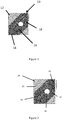
- Figure 1 shows a composite structure 10 which consists of a lay-up of multiple unidirectional carbon fiber reinforcement layers 12,14,18 which are impregnated with a resin matrix to form prepregs.
- the prepreg layers consist of prepreg without a conducting surface material 12, prepreg with a conducting surface material in the form of an expanded copper foil (ECF) 14 and a prepreg with a continuous conducting layer 18 in the form of carbon fiber tows.
- ECF expanded copper foil
- a bolt hole 16 is drilled into the composite structure and is arranged such that a mechanical fastener inserted in the hole 16 is in direct contact with the layer 18. This allows currents due to a lightning strike on or near the fastener to be conducted away from the fastener.
- Isolators 20 in the form of cuts of the carbon fiber tows 18 are present to control the direction of conduction of currents away from the fastener to a desired location in the composite structure to a point via which the current can be removed from the structure following a lightning strike.
- the composite structure of Figure 2 may be formed by providing cuts into the reinforcement fiber tows.
- the cuts or discontinuities are introduced by laser cutting during the lay-up phase of the structure. Following lay-up as the resin cures, it flows into the gap and cures thereby forming a resilient insulative barrier to electrical charges and currents.
- fibre discontinuites can be introduced per layer to either increase the efficacy of protection or to ensure that a safe zone is created which will accommodate tolerances in position of the discontinuities relative to the protected surface introduced through tolerances in manufacturing due to trimming and drilling operations.
- the isolating discontinuities are several times the critical fiber length to ensure that the mechanical performance of the composite structure is not reduced.
- the resin matrix as hereinbefore described may comprise any suitable resin including thermosets, thermoplastics or mixtures of the two.
- the resin is free from conductive ingredients which may accumulate in the fibre discontinuity and would reduce its isolating properties.
Description
- The present invention relates to a composite structure and a method for providing electrically conductive pathways in the composite, particularly but not exclusively for airframe structures.
- Aircraft are vulnerable to lightning strike. Commercial aircraft, for example, are typically struck once or twice a year. Unlike their metal counterparts, composite structures in aircraft do not readily conduct away the extreme electrical currents and electromagnetic forces generated by lightning strikes. Composite materials are either not conductive at all (e.g., fiberglass) or are significantly less conductive than metals (e.g., carbon fiber), so current from a lightning strike seeks the metal paths available. For that reason, lightning strike protection (LSP) has been a significant concern since the first composites were used on aircraft more than 30 years ago.
- If a lightning bolt strikes an unprotected structure, up to 200,000 A of electric current seeks the path of least resistance. In the process, it may vaporize metal control cables, weld hinges on control surfaces and explode fuel vapors within fuel tanks if current arcs through gaps around fasteners and also between areas of exposed edges which are at different electrical potentials (known as edge glow). These direct effects also typically include vaporization of resin in the immediate strike area, with possible burn-through of the laminate. Other potentially hazardous direct effects of a strike can include, ejection of hot gases or hot particles into the body of an aircraft structure and sparking. Indirect effects occur when magnetic fields and electrical potential differences in the structure induce transient voltages, which can damage and even destroy onboard electronics that have not been EMF (electromagnetic field) shielded or lightning protected. The need for protection of composite structures has prompted development of a number of specialized LSP materials.
- Conventional LSP strategies have three goals: provide adequate conductive paths so that lightning current remains on the structure's exterior; eliminate gaps in this conductive path to prevent arcing at attachment points and ignition of fuel vapors; and protect wiring, cables and sensitive equipment from damaging surges or transients through careful grounding, EMF shielding and application of surge suppression devices where necessary.
- Traditionally, conductive paths in composite structures have been established in one of the following ways: (1) bonding metal foil to the structure as the outside ply; (2) bonding aluminium or copper mesh to the structure either as the outside ply or embedded one ply down; or (3) incorporating strands of conductive material into the laminate. All require connecting the conductive pathways to the rest of the aircraft in order to give the current an ample number of routes to safely exit the aircraft. This is typically achieved by using metal bonding strips (i.e., electrical bonding) to connect the conductive surface layer to an internal "ground plane," which includes metal components such as engines, conduit, etc. Because lightning strikes can attach to metal fasteners in composite structures, it may be desirable to prevent arcing or sparking between them by encapsulating fastener nuts or sleeves with plastic caps or polysulfide coatings.
- For external surface protection, a number of metal and metallized fiber products have been developed, typically woven and nonwoven screens and expanded foils. These mesh-like products enable the lightning's current to quickly transmit across the structure's surface, reducing its focus. Aluminum wire was one of the first LSP materials, interwoven with carbon fiber as part of the laminate. However, using aluminum with carbon fiber risked galvanic corrosion. Copper wires relieve the threat of galvanic corrosion but are three times as heavy as aluminum. As fiberglass composites gained usage in aircraft, the industry investigated foils and then expanded foils, which can be cocured with the laminate's exterior ply. Coated fibers (nickel or copper electrodeposited onto carbon and other fibers) also are used but perform much better in EMF shielding applications than as direct lightning strike protection.
- Astrostrike aluminum mesh is produced by Astroseal Products (Chester, Conn.) from a solid foil, which is then perforated and expanded to increase formability and augment adhesion to composite structures.
- A number of suppliers provide expanded foils, which do not require a more costly weaving process to produce and reportedly offer greater drapability and conformability than wovens. Dexmet (Naugatuck, Conn.) supplies a large variety of conductive metal products for aircraft, including aluminum, copper, phosphorous bronze, titanium and other materials.
- Strikegrid is a phosphoric acid-anodized continuous expanded aluminum foil (CEAF) product supplied by Alcore (Edgewood, Md.), part of the M.C. Gill Corp. group of companies. It claims superior corrosion resistance and environmental longevity due to a proprietary coating. It is supplied on continuous rolls in 24 inch to 36 inch (610 mm to 914 mm) widths and in 2-mil and 4-mil thicknesses.
- Aluminum LSP mesh is also supplied by ECC GmbH & Co. KG (formerly C. Cramer & Co., Heek-Nienborg, Germany).
- Among the more recent developments are "all-in-one" LSP prepregs, which contain pre-embedded woven or nonwoven metal meshes. Applied first-down in layups, the products significantly reduce kitting and manufacturing costs, according to their suppliers.
- Strike Guard LSP prepreg is manufactured by APCM (Plainfield, Conn.), and sold through and supported by partner/distributor Advanced Materials and Equipment (Barkhamsted, Conn.). APCM's LSP prepregs are made from either woven or nonwoven metal mesh impregnated with hot-melt adhesive resins that are modified with additives to enhance conductivity of the matrix, making the entire prepreg a conductive system. Metal mesh options include copper, aluminum, phosphor bronze and nickel/copper-coated polyester fiber in various sizes, ranging in weight from 0.08 Ib/ft2 to 0.060 Ib/ft2. Prepregs also are available with a lightweight nonwoven fiberglass veil that enhances surface finish, reducing porosity and secondary finishing required prior to painting.
- Henkel Corp.'s (Bay Point, Calif.) LSP surfacing film combines its SynSkin composite surfacing film and Hysol film adhesives with Astroseal's lightweight conductive Astrostrike screens to provide a family of lightning strike surfacing layers. The screens also reduce the cost of surface preparation for painting, lower raw material part numbers and kitting time, and can be cocured with prepregs. SynSkin's unique combination of filler materials and resin matrix reportedly makes it nearly impossible to sand through once cured, offering dramatically better protection of the conductive screen during sand-and-fill operations than all-epoxy film adhesives.
- Cytec Engineered Materials (Tempe, Ariz.) also produces LSP products in the form of SURFACE MASTER 905 composite surfacing film.
- LSP products provide sufficient protection only when adequately incorporated into an aircraft's overall protective system. When the composite wings, fuselage skins and horizontal stabilizers are layed up, a copper tang (a thin or pointed projection that serves as an attachment point) is placed as a conductive hard point within the laminate, contacting not only the embedded copper mesh but also the bonding straps that bridge the gap between fuselage and wing.
- For its composites-intensive midsize 787 commercial passenger jet, The Boeing Co. (Seattle, Wash.) has developed a multilayered approach to its lightning strike protection strategy. Boeing uses a thin metal mesh or foil in the outer layers of the composite fuselage and wings to quickly dissipate and route charge overboard and shield onboard electronics. To avoid slight gaps between wing-skin fasteners and their holes, which could enable sparking, Boeing installs each fastener precisely and then seal it on the inside. Boeing uses non-conductive filler or glass fiber to seal edges where wing skins meet internal spars in order to prevent gaps, which could permit electrons to spray out during a lightning strike, a phenomenon referred to as "edge glow." In the fuel tanks, Boeing eliminates the threat of exploding fuel vapors by installing a nitrogen-generating system (NGS) that minimizes flammable vapors in wing tanks by filling the space with inert nitrogen gas.
-
WO2010035021 discloses a prepreg comprising resin and at least one fibre layer, and further comprising an electrically insulating layer and an electrically conducting layer, and particularly wherein the conductive layer is at or near the top surface, beneath that is the insulating layer and beneath that is a fibre/resin interleaf structure. -
WO2011114140 discloses a prepreg comprising a structural layer of conductive fibres comprising thermosetting resin in the interstices, and a first outer layer of resin comprising thermosetting resin, and comprising a population of conductive free filaments located at the interface between the structural layer and the outer resin layer which, when cured under elevated temperature, produces a cured composite material comprising a cured structural layer of packed conductive fibres and a first outer layer of cured resin, the outer layer of cured resin comprising a proportion of the population of conductive free filaments dispersed therein; and also a process for manufacturing prepregs wherein the electrically conductive fibres pass a fibre disrupting means to cause a proportion of the fibres on an external face of the sheet to become free filaments. - Conventionally the focus in LSP has been to increase the electrical conductivity of the composite structure. However, it is also important to protect critical parts of the aircraft.
- The present invention aims to obviate and/or mitigate the above described problems and/or to provide improvements generally.
- According to the invention there is provided a composite structure and a method as defined in any one of the accompanying claims.
- When fibre reinforced parts containing conductive fibres such as carbon fibers are assembled into composite structures with metallic fasteners, there is potential for lightning strike discharges directly onto any fastener exposed to the outside of the aircraft. Conductive fibres which are directly in contact with a struck fastener can therefore experience a very rapid increase in electrical charge. This can in some instances result in the development of very strong electrical fields and potentials at any exposed fibre ends present on internal surfaces of the structure. If the field is high enough to exceed the dielectric breakdown threshold of the atmosphere inside the structure, dielectric breakdown can occur allowing electrical discharge to another part of the surface at lower potential. This phenomenon is called 'edge-glow'
- When the fibre reinforced structure is a wing and the internal surface comprises part of an aircraft fuel tank, edge glow can potentially result in a fuel tank ignition which is a threat to the safety of an aircraft. For this reason there are stringent requirements for the management of this phenomenon.
- According to the present invention there is provided a composite structure comprising one or more electrically conductive pathways and one or more isolators for isolating the pathways from the bulk of the structure, the structure comprising fibre reinforcement and a reinforcement resin matrix, said pathways being formed from said fibre reinforcement and said reinforcement resin matrix; wherein the pathways are discrete and the one or more isolators comprise discontinuities in the fibre reinforcement.
- The pathways enable the protection of composite aircraft structures from electrical discharge phenomena such as edge glow by conducting the electricity away from critical parts. In addition the pathways enable control of the direction of electrical conductivity.
- In an embodiment, the pathways are formed from the same fibre reinforcement and the same resin matrix as the fibre reinforcement and matrix of the bulk of the structure.
- The introduction of one or more discontinuities into the fibres which connect a metal element of the composite structure which may be susceptible to lightning strike protects any internal surface from edge glow.
- The isolators comprise discontinuities in the fibre reinforcement. The fibre discontinuities may be introduced in specific locations of a ply during the laminate layup process to form the composite structure. This is done in such as way so as to ensure that the distance between discontinuities is longer than the critical fibre length for the resin/fibre combination to avoid compromising mechanical properties.
- The critical fiber length (Lc) is defined as

- One dimension of the isolator which extends in the direction of the fibers may correspond to n x critical fibre length wherein n = 1 to 100, preferably n = 1 to 50, more preferably n = 1 to 10.
- In a further embodiment of the invention, the isolators are formed by an isolator resin matrix.
- In another embodiment of the invention, there is provided a method of controlling current paths in a composite structure comprising one or more discrete electrically conductive pathways in the structure, the structure comprising fibre reinforcement and a reinforcement resin matrix, said pathways being formed from said fibre reinforcement and said reinforcement resin matrix; said method comprising providing one or more isolators isolating the pathways from the bulk of the structure, said one or more isolators comprising discontinuities in the fibre reinforcement.
- In a preferred embodiment, the composite structure is prepared from a lay-up of resin preimpregnated fibrous reinforcement material layers (or prepreg layers). The layers or plies are arranged to connect metallic elements directly to the internal surface of structure. One or more cuts are introduced in one or more plies to ensure that the pathway is isolated. The structure is then cured which results in the cut discontinuities or isolators being filled with resin.
- The cut or discontinuity may be introduced in any conceivable way including slitting with a blade, laser cutting, stretching, ultrasonic disruption of the fibres. It may also be introduced automatically with attachments to robotic equipment such as ATL, AFP or other systems, or even by a manual operation.
- During cure the resin from the composite flows into the cut and cures thereby forming a resilient insulative barrier to charge being conducted from the metallic element to the surface. This protects against edge glow. Several fibre discontinuites can be introduced per layer to either increase the efficacy of protection or to ensure that a safe zone is created which will accommodate tolerances in the position of the discontinuities relative to the protected surface introduced through tolerances in manufacturing due to trimming and drilling operations
- Finally the composite structure may comprise other equipment for sensing or structural health monitoring.
- Specific embodiments of the invention will now be described by way of Example only and with reference to the accompanying drawings in which:
-
Figure 1 presents a diagrammatic plan view of a structure not according to an embodiment of the invention; and -
Figure 2 presents a diagrammatic plan view of another structure according to an embodiment of the invention. - The present invention provides a composite structure comprising pathways for connecting connecting metallic elements to one another. The pathways are isolated from the bulk of the composite structure by means of isolators. These isolators are preferably formed by the reinforcement resin of the structure.
- In aircraft, pathways may preferably be provided between mechanical fasteners and/or framing and/or LSP surface structures and/or engines and/or other metallic elements such as bond straps.
- The pathways may be formed from conductive reinforcement fibers such as carbon fiber.
- Alternatively, metallized fabrics and/or metallized fibers may be used. Examples of such fibers and/or fabrics will now be briefly disclosed. Diamond Fiber Composites (Cincinnati, Ohio) coats carbon fibers with a wide variety of metals including nickel, copper, silver, gold, palladium, platinum and metal hybrids (multilayer coatings) using a chemically based coating process that provides a uniform coating. These coated fibers may be obtained as continuous fiber lengths, chopped fibers, woven fabrics and nonwoven veils/mats.
- Electro Fiber Technologies (Stratford, Conn.) offers single or dual metal hybrids coated onto carbon, graphite, glass, polyester and other synthetic fibers. The company supplies chopped fibers (down to 1 mm/0.04 inch in length) and continuous tows from 3K to 80K as well as nonwoven veils and mats.
- Technical Fibre Products (Newburgh, N.Y.) supplies electrically conductive nonwoven mats and veils using carbon, nickel-coated carbon, aluminized glass, silicon carbide, stainless steel and nickel fibers.
- Textile Products Inc. (Anaheim, Calif.) supplies a Style #4607 216 g/m2 carbon/aluminum hybrid fabric made with AS4-3K carbon fiber and aluminum wire. It also supplies a Style #4608 218 g/m2 hybrid with T650/35-3K carbon fiber and aluminum wire. Both are plain weaves, 14 mils thick and 107 cm/42 inches wide.
- Varinit (Greenville, S.C.) supplies electrically conductive reinforcing fabrics, developing and manufacturing products to meet customer specifications.
- An embodiment of the invention is illustrated with respect to
Figures 1 and 2. Figure 1 shows acomposite structure 10 which consists of a lay-up of multiple unidirectional carbon fiber reinforcement layers 12,14,18 which are impregnated with a resin matrix to form prepregs. The prepreg layers consist of prepreg without a conductingsurface material 12, prepreg with a conducting surface material in the form of an expanded copper foil (ECF) 14 and a prepreg with acontinuous conducting layer 18 in the form of carbon fiber tows. Abolt hole 16 is drilled into the composite structure and is arranged such that a mechanical fastener inserted in thehole 16 is in direct contact with thelayer 18. This allows currents due to a lightning strike on or near the fastener to be conducted away from the fastener. - In
Figure 2 , the reference numerals correspond to the same parts ofFigure 1 .Isolators 20 in the form of cuts of the carbon fiber tows 18 are present to control the direction of conduction of currents away from the fastener to a desired location in the composite structure to a point via which the current can be removed from the structure following a lightning strike. - The composite structure of
Figure 2 may be formed by providing cuts into the reinforcement fiber tows. The cuts or discontinuities are introduced by laser cutting during the lay-up phase of the structure. Following lay-up as the resin cures, it flows into the gap and cures thereby forming a resilient insulative barrier to electrical charges and currents. - Several fibre discontinuites can be introduced per layer to either increase the efficacy of protection or to ensure that a safe zone is created which will accommodate tolerances in position of the discontinuities relative to the protected surface introduced through tolerances in manufacturing due to trimming and drilling operations.
- The isolating discontinuities are several times the critical fiber length to ensure that the mechanical performance of the composite structure is not reduced.
- The resin matrix as hereinbefore described may comprise any suitable resin including thermosets, thermoplastics or mixtures of the two. Preferably the resin is free from conductive ingredients which may accumulate in the fibre discontinuity and would reduce its isolating properties.
- There is thus provided a structure and a method which enables effective control of electrical charges and/or currents in composite structures, particularly but not exclusively in composite aircraft or windenergy structures.
Claims (11)
- A composite structure (10) comprising one or more electrically conductive pathways (18) and one or more isolators (20) for isolating the pathways (18) from the bulk of the structure (10), the structure (10) comprising fibre reinforcement and a reinforcement resin matrix, said pathways (18) being formed from said fibre reinforcement and said reinforcement resin matrix; wherein the pathways (18) are discrete and the one or more isolators (20) comprise discontinuities in the fibre reinforcement
- A structure (10) according to claim 1, wherein the pathways (18) are formed from the same fibre reinforcement and the same resin matrix as the bulk of the structure.
- A structure (10) according to claim 1 or claim 2, wherein the one or more isolators (20) are formed by an isolator resin matrix.
- A structure (10) of claim 3, wherein the isolator resin matrix comprises the reinforcement resin matrix.
- A structure (10) according to any of claims 1 to 4, wherein the structure (10) comprises multiple ply layers of fibre reinforcement, the one or more isolators (20) extending across at least two ply layers.
- A structure (10) according to any of the preceding claims, wherein the length of the one or more isolators (20) corresponds to the n x critical fibre length wherein n = 1 to 10, preferably n = 1 to 5.
- A structure (10) according to any of the preceding claims, wherein the conductive pathways are formed by unidirectional carbon fibre.
- A structure according (10) to claim 8, wherein the carbon fibre is coated with a metal.
- A method of controlling current paths in a composite structure comprising a one or more discrete electrically conductive pathways in the structure, the structure comprising fibre reinforcement and a reinforcement resin matrix, said pathways being formed from said fibre reinforcement and said reinforcement resin matrix; said method comprising providing one or more isolators isolating the pathways from the bulk of the structure, said one or more isolators comprising discontinuities in the fibre reinforcement.
- A method of claim 9, wherein the composite structure is prepared from a lay-up of resin preimpregnated fibrous reinforcement material layers, the layers being arranged to connect metallic elements directly to the internal pathway of the structure.
- A method according to any of claims 9 or 10, wherein, following cure, the one or more isolators comprise resin filled discontinuities.
Applications Claiming Priority (2)
| Application Number | Priority Date | Filing Date | Title |
|---|---|---|---|
| GB1322767.3A GB2522841B (en) | 2013-12-20 | 2013-12-20 | Composite structure |
| PCT/EP2014/078456 WO2015091794A1 (en) | 2013-12-20 | 2014-12-18 | Composite structure |
Publications (2)
| Publication Number | Publication Date |
|---|---|
| EP3083231A1 EP3083231A1 (en) | 2016-10-26 |
| EP3083231B1 true EP3083231B1 (en) | 2020-06-03 |
Family
ID=50071298
Family Applications (1)
| Application Number | Title | Priority Date | Filing Date |
|---|---|---|---|
| EP14815712.6A Active EP3083231B1 (en) | 2013-12-20 | 2014-12-18 | Composite structure |
Country Status (7)
| Country | Link |
|---|---|
| US (1) | US20170028673A1 (en) |
| EP (1) | EP3083231B1 (en) |
| CN (1) | CN105829092A (en) |
| ES (1) | ES2805365T3 (en) |
| GB (1) | GB2522841B (en) |
| RU (1) | RU2676623C1 (en) |
| WO (1) | WO2015091794A1 (en) |
Families Citing this family (10)
| Publication number | Priority date | Publication date | Assignee | Title |
|---|---|---|---|---|
| JP6263504B2 (en) | 2015-08-25 | 2018-01-17 | 矢崎総業株式会社 | Conductive resin body and vehicle ground structure |
| US10329030B2 (en) * | 2016-03-04 | 2019-06-25 | The Boeing Company | Conductive radius filler system and method |
| US10921859B2 (en) * | 2017-04-10 | 2021-02-16 | Securaplane Technologies, Inc. | Composite electronics cases and methods of making and using the same |
| CA3087205A1 (en) * | 2017-12-29 | 2019-07-04 | Henkel IP & Holding GmbH | Multifunctional surfacing films |
| CN110444320B (en) * | 2019-08-09 | 2020-10-09 | 大连理工大学 | High-strength high-conductivity carbon fiber reinforced aluminum-based composite wire and preparation method thereof |
| US11376812B2 (en) | 2020-02-11 | 2022-07-05 | Helicoid Industries Inc. | Shock and impact resistant structures |
| GB202018581D0 (en) * | 2020-11-26 | 2021-01-13 | Bae Systems Plc | Enhanced automated fibre placement method |
| WO2022256022A1 (en) | 2021-06-01 | 2022-12-08 | Helicoid Industries Inc. | Containers and methods for protecting pressure vessels |
| US11852297B2 (en) | 2021-06-01 | 2023-12-26 | Helicoid Industries Inc. | Containers and methods for protecting pressure vessels |
| WO2024006078A1 (en) | 2022-06-27 | 2024-01-04 | Helicoid Industries Inc. | High impact-resistant, reinforced fiber for leading edge protection of aerodynamic structures |
Family Cites Families (14)
| Publication number | Priority date | Publication date | Assignee | Title |
|---|---|---|---|---|
| GB8628555D0 (en) * | 1986-11-28 | 1987-01-07 | British Aerospace | Anti lightning strike fasteners |
| DK178207B1 (en) * | 2004-01-23 | 2015-08-17 | Lm Wind Power As | Wing for a wind power plant comprising segmented lightning conductors and method of manufacturing them |
| DE05819580T1 (en) * | 2004-09-01 | 2008-04-24 | Bell Helicopter Textron, Inc., Fort Worth | Press-formed parts with an embedded conductor layer and manufacturing method therefor |
| EP2363429A1 (en) * | 2006-03-10 | 2011-09-07 | Goodrich Corporation | Low density lightining strike protection for use in airplanes |
| US7277266B1 (en) * | 2006-03-29 | 2007-10-02 | The Boeing Company | Lightning protection system for composite structure |
| WO2007130979A2 (en) * | 2006-05-02 | 2007-11-15 | Rohr, Inc. | Modification of reinforcing fiber tows used in composite materials by using nanoreinforcements |
| GB2473226A (en) * | 2009-09-04 | 2011-03-09 | Hexcel Composites Ltd | Composite materials |
| GB0622060D0 (en) * | 2006-11-06 | 2006-12-13 | Hexcel Composites Ltd | Improved composite materials |
| NZ577811A (en) * | 2006-11-30 | 2011-04-29 | Ducane Res And Dev Pty And Ltd | Sanitary water conservation device |
| US20080173060A1 (en) * | 2006-12-14 | 2008-07-24 | Undultec, Inc. | Method and apparatus for forming undulating conduit |
| GB0805640D0 (en) * | 2008-03-28 | 2008-04-30 | Hexcel Composites Ltd | Improved composite materials |
| GB0817591D0 (en) * | 2008-09-26 | 2008-11-05 | Hexcel Composites Ltd | Improvements in composite materials |
| US10090076B2 (en) * | 2009-06-22 | 2018-10-02 | Condalign As | Anisotropic conductive polymer material |
| GB2478749A (en) * | 2010-03-17 | 2011-09-21 | Hexcel Composites Ltd | Composite materials of reduced electrical resistance |
-
2013
- 2013-12-20 GB GB1322767.3A patent/GB2522841B/en active Active
-
2014
- 2014-12-18 WO PCT/EP2014/078456 patent/WO2015091794A1/en active Application Filing
- 2014-12-18 US US15/100,301 patent/US20170028673A1/en not_active Abandoned
- 2014-12-18 RU RU2016129268A patent/RU2676623C1/en active
- 2014-12-18 ES ES14815712T patent/ES2805365T3/en active Active
- 2014-12-18 CN CN201480068612.2A patent/CN105829092A/en active Pending
- 2014-12-18 EP EP14815712.6A patent/EP3083231B1/en active Active
Non-Patent Citations (1)
| Title |
|---|
| None * |
Also Published As
| Publication number | Publication date |
|---|---|
| EP3083231A1 (en) | 2016-10-26 |
| GB2522841A (en) | 2015-08-12 |
| US20170028673A1 (en) | 2017-02-02 |
| RU2676623C1 (en) | 2019-01-09 |
| ES2805365T3 (en) | 2021-02-11 |
| WO2015091794A1 (en) | 2015-06-25 |
| RU2016129268A (en) | 2018-01-25 |
| GB2522841B (en) | 2018-08-15 |
| GB201322767D0 (en) | 2014-02-05 |
| CN105829092A (en) | 2016-08-03 |
Similar Documents
| Publication | Publication Date | Title |
|---|---|---|
| EP3083231B1 (en) | Composite structure | |
| AU655463B2 (en) | A structural component | |
| EP3153410B1 (en) | Methods for diverting lightning current from skin fasteners in composite, non-metallic structures | |
| US8146861B2 (en) | Component with carbon nanotubes | |
| EP2432634B1 (en) | Method for forming a structure having a lightning strike protection and lightning strike protection structure | |
| CN103842168B (en) | Molybdenum composite mixed layer casting die and method | |
| EP2143638A2 (en) | Lightning protection system for an aircraft composite structure | |
| EP2401195B1 (en) | Distributing power in systems having a composite structure | |
| WO2006086083A2 (en) | Method and system for lightning current conduction protection using foil bonded strips | |
| EP1935631B1 (en) | Electrical connects for charge distribution applique | |
| EP3156321B1 (en) | Composite stiffener with integral conductive element | |
| EP1549545B1 (en) | Lightning strike protection and grounding of a composite aircraft panel | |
| EP3106291B1 (en) | Enhancing z-conductivity in carbon fiber reinforced plastic composite layups | |
| WO1984001487A1 (en) | Integral lightning protection system for composite aircraft skins | |
| EP0835049A2 (en) | Apparatus and methods of providing corrosion resistant conductive path across non conductive joints or gaps | |
| US20110318981A1 (en) | Composite material structure protected against the effects of lightning | |
| EP2465776B1 (en) | Lightning and corrosion protection arrangement in an aircraft structural component | |
| EP2979976B1 (en) | Fuel tank, main wings, aircraft fuselage, aircraft, and moving body | |
| EP2628589B1 (en) | Composite layers with exposed reinforcement | |
| EP3000736A1 (en) | Method for mitigating edge glow and resulting composite structure | |
| Fei et al. | Certification of Radome Lightning Direct Effects Protection |
Legal Events
| Date | Code | Title | Description |
|---|---|---|---|
| PUAI | Public reference made under article 153(3) epc to a published international application that has entered the european phase |
Free format text: ORIGINAL CODE: 0009012 |
|
| 17P | Request for examination filed |
Effective date: 20160527 |
|
| AK | Designated contracting states |
Kind code of ref document: A1 Designated state(s): AL AT BE BG CH CY CZ DE DK EE ES FI FR GB GR HR HU IE IS IT LI LT LU LV MC MK MT NL NO PL PT RO RS SE SI SK SM TR |
|
| AX | Request for extension of the european patent |
Extension state: BA ME |
|
| DAX | Request for extension of the european patent (deleted) | ||
| STAA | Information on the status of an ep patent application or granted ep patent |
Free format text: STATUS: EXAMINATION IS IN PROGRESS |
|
| 17Q | First examination report despatched |
Effective date: 20181123 |
|
| GRAP | Despatch of communication of intention to grant a patent |
Free format text: ORIGINAL CODE: EPIDOSNIGR1 |
|
| STAA | Information on the status of an ep patent application or granted ep patent |
Free format text: STATUS: GRANT OF PATENT IS INTENDED |
|
| INTG | Intention to grant announced |
Effective date: 20200110 |
|
| GRAS | Grant fee paid |
Free format text: ORIGINAL CODE: EPIDOSNIGR3 |
|
| GRAA | (expected) grant |
Free format text: ORIGINAL CODE: 0009210 |
|
| STAA | Information on the status of an ep patent application or granted ep patent |
Free format text: STATUS: THE PATENT HAS BEEN GRANTED |
|
| AK | Designated contracting states |
Kind code of ref document: B1 Designated state(s): AL AT BE BG CH CY CZ DE DK EE ES FI FR GB GR HR HU IE IS IT LI LT LU LV MC MK MT NL NO PL PT RO RS SE SI SK SM TR |
|
| RAP1 | Party data changed (applicant data changed or rights of an application transferred) |
Owner name: HEXCEL COMPOSITES LIMITED |
|
| REG | Reference to a national code |
Ref country code: GB Ref legal event code: FG4D |
|
| REG | Reference to a national code |
Ref country code: AT Ref legal event code: REF Ref document number: 1276596 Country of ref document: AT Kind code of ref document: T Effective date: 20200615 Ref country code: CH Ref legal event code: EP |
|
| REG | Reference to a national code |
Ref country code: DE Ref legal event code: R096 Ref document number: 602014066289 Country of ref document: DE |
|
| REG | Reference to a national code |
Ref country code: LT Ref legal event code: MG4D |
|
| PG25 | Lapsed in a contracting state [announced via postgrant information from national office to epo] |
Ref country code: GR Free format text: LAPSE BECAUSE OF FAILURE TO SUBMIT A TRANSLATION OF THE DESCRIPTION OR TO PAY THE FEE WITHIN THE PRESCRIBED TIME-LIMIT Effective date: 20200904 Ref country code: NO Free format text: LAPSE BECAUSE OF FAILURE TO SUBMIT A TRANSLATION OF THE DESCRIPTION OR TO PAY THE FEE WITHIN THE PRESCRIBED TIME-LIMIT Effective date: 20200903 Ref country code: SE Free format text: LAPSE BECAUSE OF FAILURE TO SUBMIT A TRANSLATION OF THE DESCRIPTION OR TO PAY THE FEE WITHIN THE PRESCRIBED TIME-LIMIT Effective date: 20200603 Ref country code: LT Free format text: LAPSE BECAUSE OF FAILURE TO SUBMIT A TRANSLATION OF THE DESCRIPTION OR TO PAY THE FEE WITHIN THE PRESCRIBED TIME-LIMIT Effective date: 20200603 Ref country code: FI Free format text: LAPSE BECAUSE OF FAILURE TO SUBMIT A TRANSLATION OF THE DESCRIPTION OR TO PAY THE FEE WITHIN THE PRESCRIBED TIME-LIMIT Effective date: 20200603 |
|
| REG | Reference to a national code |
Ref country code: NL Ref legal event code: MP Effective date: 20200603 |
|
| PG25 | Lapsed in a contracting state [announced via postgrant information from national office to epo] |
Ref country code: LV Free format text: LAPSE BECAUSE OF FAILURE TO SUBMIT A TRANSLATION OF THE DESCRIPTION OR TO PAY THE FEE WITHIN THE PRESCRIBED TIME-LIMIT Effective date: 20200603 Ref country code: HR Free format text: LAPSE BECAUSE OF FAILURE TO SUBMIT A TRANSLATION OF THE DESCRIPTION OR TO PAY THE FEE WITHIN THE PRESCRIBED TIME-LIMIT Effective date: 20200603 Ref country code: RS Free format text: LAPSE BECAUSE OF FAILURE TO SUBMIT A TRANSLATION OF THE DESCRIPTION OR TO PAY THE FEE WITHIN THE PRESCRIBED TIME-LIMIT Effective date: 20200603 Ref country code: BG Free format text: LAPSE BECAUSE OF FAILURE TO SUBMIT A TRANSLATION OF THE DESCRIPTION OR TO PAY THE FEE WITHIN THE PRESCRIBED TIME-LIMIT Effective date: 20200903 |
|
| REG | Reference to a national code |
Ref country code: AT Ref legal event code: MK05 Ref document number: 1276596 Country of ref document: AT Kind code of ref document: T Effective date: 20200603 |
|
| PG25 | Lapsed in a contracting state [announced via postgrant information from national office to epo] |
Ref country code: NL Free format text: LAPSE BECAUSE OF FAILURE TO SUBMIT A TRANSLATION OF THE DESCRIPTION OR TO PAY THE FEE WITHIN THE PRESCRIBED TIME-LIMIT Effective date: 20200603 Ref country code: AL Free format text: LAPSE BECAUSE OF FAILURE TO SUBMIT A TRANSLATION OF THE DESCRIPTION OR TO PAY THE FEE WITHIN THE PRESCRIBED TIME-LIMIT Effective date: 20200603 |
|
| PG25 | Lapsed in a contracting state [announced via postgrant information from national office to epo] |
Ref country code: RO Free format text: LAPSE BECAUSE OF FAILURE TO SUBMIT A TRANSLATION OF THE DESCRIPTION OR TO PAY THE FEE WITHIN THE PRESCRIBED TIME-LIMIT Effective date: 20200603 Ref country code: PT Free format text: LAPSE BECAUSE OF FAILURE TO SUBMIT A TRANSLATION OF THE DESCRIPTION OR TO PAY THE FEE WITHIN THE PRESCRIBED TIME-LIMIT Effective date: 20201006 Ref country code: CZ Free format text: LAPSE BECAUSE OF FAILURE TO SUBMIT A TRANSLATION OF THE DESCRIPTION OR TO PAY THE FEE WITHIN THE PRESCRIBED TIME-LIMIT Effective date: 20200603 Ref country code: SM Free format text: LAPSE BECAUSE OF FAILURE TO SUBMIT A TRANSLATION OF THE DESCRIPTION OR TO PAY THE FEE WITHIN THE PRESCRIBED TIME-LIMIT Effective date: 20200603 Ref country code: AT Free format text: LAPSE BECAUSE OF FAILURE TO SUBMIT A TRANSLATION OF THE DESCRIPTION OR TO PAY THE FEE WITHIN THE PRESCRIBED TIME-LIMIT Effective date: 20200603 Ref country code: EE Free format text: LAPSE BECAUSE OF FAILURE TO SUBMIT A TRANSLATION OF THE DESCRIPTION OR TO PAY THE FEE WITHIN THE PRESCRIBED TIME-LIMIT Effective date: 20200603 |
|
| REG | Reference to a national code |
Ref country code: ES Ref legal event code: FG2A Ref document number: 2805365 Country of ref document: ES Kind code of ref document: T3 Effective date: 20210211 |
|
| PG25 | Lapsed in a contracting state [announced via postgrant information from national office to epo] |
Ref country code: IS Free format text: LAPSE BECAUSE OF FAILURE TO SUBMIT A TRANSLATION OF THE DESCRIPTION OR TO PAY THE FEE WITHIN THE PRESCRIBED TIME-LIMIT Effective date: 20201003 Ref country code: PL Free format text: LAPSE BECAUSE OF FAILURE TO SUBMIT A TRANSLATION OF THE DESCRIPTION OR TO PAY THE FEE WITHIN THE PRESCRIBED TIME-LIMIT Effective date: 20200603 Ref country code: SK Free format text: LAPSE BECAUSE OF FAILURE TO SUBMIT A TRANSLATION OF THE DESCRIPTION OR TO PAY THE FEE WITHIN THE PRESCRIBED TIME-LIMIT Effective date: 20200603 |
|
| REG | Reference to a national code |
Ref country code: DE Ref legal event code: R097 Ref document number: 602014066289 Country of ref document: DE |
|
| PLBE | No opposition filed within time limit |
Free format text: ORIGINAL CODE: 0009261 |
|
| STAA | Information on the status of an ep patent application or granted ep patent |
Free format text: STATUS: NO OPPOSITION FILED WITHIN TIME LIMIT |
|
| PG25 | Lapsed in a contracting state [announced via postgrant information from national office to epo] |
Ref country code: DK Free format text: LAPSE BECAUSE OF FAILURE TO SUBMIT A TRANSLATION OF THE DESCRIPTION OR TO PAY THE FEE WITHIN THE PRESCRIBED TIME-LIMIT Effective date: 20200603 |
|
| 26N | No opposition filed |
Effective date: 20210304 |
|
| PG25 | Lapsed in a contracting state [announced via postgrant information from national office to epo] |
Ref country code: SI Free format text: LAPSE BECAUSE OF FAILURE TO SUBMIT A TRANSLATION OF THE DESCRIPTION OR TO PAY THE FEE WITHIN THE PRESCRIBED TIME-LIMIT Effective date: 20200603 |
|
| REG | Reference to a national code |
Ref country code: CH Ref legal event code: PL |
|
| PG25 | Lapsed in a contracting state [announced via postgrant information from national office to epo] |
Ref country code: MC Free format text: LAPSE BECAUSE OF FAILURE TO SUBMIT A TRANSLATION OF THE DESCRIPTION OR TO PAY THE FEE WITHIN THE PRESCRIBED TIME-LIMIT Effective date: 20200603 |
|
| REG | Reference to a national code |
Ref country code: BE Ref legal event code: MM Effective date: 20201231 |
|
| PG25 | Lapsed in a contracting state [announced via postgrant information from national office to epo] |
Ref country code: LU Free format text: LAPSE BECAUSE OF NON-PAYMENT OF DUE FEES Effective date: 20201218 Ref country code: IE Free format text: LAPSE BECAUSE OF NON-PAYMENT OF DUE FEES Effective date: 20201218 |
|
| PG25 | Lapsed in a contracting state [announced via postgrant information from national office to epo] |
Ref country code: CH Free format text: LAPSE BECAUSE OF NON-PAYMENT OF DUE FEES Effective date: 20201231 Ref country code: LI Free format text: LAPSE BECAUSE OF NON-PAYMENT OF DUE FEES Effective date: 20201231 |
|
| PG25 | Lapsed in a contracting state [announced via postgrant information from national office to epo] |
Ref country code: TR Free format text: LAPSE BECAUSE OF FAILURE TO SUBMIT A TRANSLATION OF THE DESCRIPTION OR TO PAY THE FEE WITHIN THE PRESCRIBED TIME-LIMIT Effective date: 20200603 Ref country code: MT Free format text: LAPSE BECAUSE OF FAILURE TO SUBMIT A TRANSLATION OF THE DESCRIPTION OR TO PAY THE FEE WITHIN THE PRESCRIBED TIME-LIMIT Effective date: 20200603 Ref country code: CY Free format text: LAPSE BECAUSE OF FAILURE TO SUBMIT A TRANSLATION OF THE DESCRIPTION OR TO PAY THE FEE WITHIN THE PRESCRIBED TIME-LIMIT Effective date: 20200603 |
|
| PG25 | Lapsed in a contracting state [announced via postgrant information from national office to epo] |
Ref country code: MK Free format text: LAPSE BECAUSE OF FAILURE TO SUBMIT A TRANSLATION OF THE DESCRIPTION OR TO PAY THE FEE WITHIN THE PRESCRIBED TIME-LIMIT Effective date: 20200603 |
|
| PG25 | Lapsed in a contracting state [announced via postgrant information from national office to epo] |
Ref country code: BE Free format text: LAPSE BECAUSE OF NON-PAYMENT OF DUE FEES Effective date: 20201231 |
|
| PGFP | Annual fee paid to national office [announced via postgrant information from national office to epo] |
Ref country code: ES Payment date: 20230110 Year of fee payment: 9 |
|
| P01 | Opt-out of the competence of the unified patent court (upc) registered |
Effective date: 20230530 |
|
| PGFP | Annual fee paid to national office [announced via postgrant information from national office to epo] |
Ref country code: GB Payment date: 20231026 Year of fee payment: 10 |
|
| PGFP | Annual fee paid to national office [announced via postgrant information from national office to epo] |
Ref country code: IT Payment date: 20231110 Year of fee payment: 10 Ref country code: FR Payment date: 20231009 Year of fee payment: 10 Ref country code: DE Payment date: 20231024 Year of fee payment: 10 |