EP3299288B1 - Hochgeschwindigkeitsmotoruntersetzungsgetriebe - Google Patents
Hochgeschwindigkeitsmotoruntersetzungsgetriebe Download PDFInfo
- Publication number
- EP3299288B1 EP3299288B1 EP17192688.4A EP17192688A EP3299288B1 EP 3299288 B1 EP3299288 B1 EP 3299288B1 EP 17192688 A EP17192688 A EP 17192688A EP 3299288 B1 EP3299288 B1 EP 3299288B1
- Authority
- EP
- European Patent Office
- Prior art keywords
- engine
- main rotor
- gearbox
- gear
- speed
- Prior art date
- Legal status (The legal status is an assumption and is not a legal conclusion. Google has not performed a legal analysis and makes no representation as to the accuracy of the status listed.)
- Active
Links
Images




Classifications
-
- F—MECHANICAL ENGINEERING; LIGHTING; HEATING; WEAPONS; BLASTING
- F16—ENGINEERING ELEMENTS AND UNITS; GENERAL MEASURES FOR PRODUCING AND MAINTAINING EFFECTIVE FUNCTIONING OF MACHINES OR INSTALLATIONS; THERMAL INSULATION IN GENERAL
- F16H—GEARING
- F16H37/00—Combinations of mechanical gearings, not provided for in groups F16H1/00 - F16H35/00
- F16H37/02—Combinations of mechanical gearings, not provided for in groups F16H1/00 - F16H35/00 comprising essentially only toothed or friction gearings
- F16H37/04—Combinations of toothed gearings only
- F16H37/042—Combinations of toothed gearings only change gear transmissions in group arrangement
-
- B—PERFORMING OPERATIONS; TRANSPORTING
- B64—AIRCRAFT; AVIATION; COSMONAUTICS
- B64C—AEROPLANES; HELICOPTERS
- B64C27/00—Rotorcraft; Rotors peculiar thereto
- B64C27/04—Helicopters
- B64C27/12—Rotor drives
- B64C27/14—Direct drive between power plant and rotor hub
-
- B—PERFORMING OPERATIONS; TRANSPORTING
- B64—AIRCRAFT; AVIATION; COSMONAUTICS
- B64D—EQUIPMENT FOR FITTING IN OR TO AIRCRAFT; FLIGHT SUITS; PARACHUTES; ARRANGEMENT OR MOUNTING OF POWER PLANTS OR PROPULSION TRANSMISSIONS IN AIRCRAFT
- B64D35/00—Transmitting power from power plants to propellers or rotors; Arrangements of transmissions
-
- B—PERFORMING OPERATIONS; TRANSPORTING
- B64—AIRCRAFT; AVIATION; COSMONAUTICS
- B64D—EQUIPMENT FOR FITTING IN OR TO AIRCRAFT; FLIGHT SUITS; PARACHUTES; ARRANGEMENT OR MOUNTING OF POWER PLANTS OR PROPULSION TRANSMISSIONS IN AIRCRAFT
- B64D35/00—Transmitting power from power plants to propellers or rotors; Arrangements of transmissions
- B64D35/08—Transmitting power from power plants to propellers or rotors; Arrangements of transmissions characterised by the transmission being driven by a plurality of power plants
-
- F—MECHANICAL ENGINEERING; LIGHTING; HEATING; WEAPONS; BLASTING
- F16—ENGINEERING ELEMENTS AND UNITS; GENERAL MEASURES FOR PRODUCING AND MAINTAINING EFFECTIVE FUNCTIONING OF MACHINES OR INSTALLATIONS; THERMAL INSULATION IN GENERAL
- F16H—GEARING
- F16H57/00—General details of gearing
- F16H57/02—Gearboxes; Mounting gearing therein
-
- F—MECHANICAL ENGINEERING; LIGHTING; HEATING; WEAPONS; BLASTING
- F16—ENGINEERING ELEMENTS AND UNITS; GENERAL MEASURES FOR PRODUCING AND MAINTAINING EFFECTIVE FUNCTIONING OF MACHINES OR INSTALLATIONS; THERMAL INSULATION IN GENERAL
- F16H—GEARING
- F16H57/00—General details of gearing
- F16H57/02—Gearboxes; Mounting gearing therein
- F16H2057/02013—Extension units for gearboxes, e.g. additional units attached to a main gear
-
- F—MECHANICAL ENGINEERING; LIGHTING; HEATING; WEAPONS; BLASTING
- F16—ENGINEERING ELEMENTS AND UNITS; GENERAL MEASURES FOR PRODUCING AND MAINTAINING EFFECTIVE FUNCTIONING OF MACHINES OR INSTALLATIONS; THERMAL INSULATION IN GENERAL
- F16H—GEARING
- F16H57/00—General details of gearing
- F16H57/02—Gearboxes; Mounting gearing therein
- F16H2057/02039—Gearboxes for particular applications
- F16H2057/02043—Gearboxes for particular applications for vehicle transmissions
-
- F—MECHANICAL ENGINEERING; LIGHTING; HEATING; WEAPONS; BLASTING
- F16—ENGINEERING ELEMENTS AND UNITS; GENERAL MEASURES FOR PRODUCING AND MAINTAINING EFFECTIVE FUNCTIONING OF MACHINES OR INSTALLATIONS; THERMAL INSULATION IN GENERAL
- F16H—GEARING
- F16H2702/00—Combinations of two or more transmissions
Definitions
- the present invention relates in general to the field of gears for rotorcraft, and more particularly, to high-speed gearing and continued torque transmission in the event of a gear failure, including a loss-of-lubrication event.
- rotorcraft and rotorcraft drive systems have been improved to reduce the possibility of failure during flight.
- a number of modifications have been made to drive systems to improve reliability.
- a number of failures continue to occur that affect rotorcraft performance.
- One example of a problem with current rotorcraft drive systems is that, in some instances, the failure of single drive system component leads to failure of the entire drive system.
- Another example is a loss of lubrication event that causes the seizing of drive system subcomponents such as gearboxes or accessories connected to the main rotor gearbox.
- the failure of a single gearbox or shaft connected to the main rotor gearbox can significantly impact operations. For example, if there is a loss of lubrication to a gearbox, the gearbox seizes up causing damage to upstream or downstream components. The same can occur when a shaft becomes unbalanced (or breaks), which can damage couplings, gearboxes and even the main rotor gearbox.
- a portion of a drive system experiences a failure or reduction in performance, the concomitant reduction in power leads to challenges with flight performance.
- Prior art gearboxes typically require external oil coolers and have pressurized oil leak paths. Further, they typically have external grease packed bearings. All of these features are potential failure points and require frequent maintenance and servicing. Systems and methods that reduce or eliminate dependence on such features are desirable.
- Prior art rotorcraft drive systems use high-speed gearing systems that are susceptible to inabilities to continue torque transmission, particularly in a loss-of-lubrication scenario, and that provide potential failure points that decrease safety.
- One such gearbox is taught in U.S. Patent No. 8,740,565 , issued to Perkinson, and entitled, "Modular Counter Rotating Propeller System.” Briefly, this inventor teaches a self-contained counter rotating turbo prop system that is driven by a gas turbine engine through a reduction gearbox. A gear train is housed separately from the reduction gearbox that provides the counter-rotation of a first and a second plurality of propeller blades. The entire counter-rotating propeller system is disposed within cowlings and is separate from the gas turbine engine and reduction gearbox.
- Helicopter Drive System On-condition Maintenance Capability (USAAMRDL-TR-75-57, ADA028414, https://apps.dtic.mil/dtic/tr/fulltext/u2/a028414.pdf) discloses the drive train system of a CH53/CH54 rotorcraft including the main gearbox and the two reduction gearboxes, also called nose gearboxes.
- US6302356B1 discloses a twin turbine engine helicopter having a two-stage main reduction gearbox, the input stage having a speed reduction ratio exceeding 5.5:1, into an epicyclic gear train second stage ratio about 6:1 for approximately 30:1 or higher overall ratio output to the main rotor.
- the first stage uses face gears, or bevel gears, with a reduction greater than 5.5:1 and a second stage epicyclic gear train using single or double row helical or spur gears.
- the first stage gears are straddle mounted in the housing.
- EP0739815A1 discloses engines directly coupled to an engine deceleration device composed of a traction speed change mechanism and a planetary speed change mechanism, and is decelerated at a desired speed change ratio, and rotate and drive a collector gear and a main rotor shaft.
- the collector gear rotates and drives accessories and a tail rotor through a second traction speed change mechanism changing speed in inverse number of the speed change ratio of the traction speed change mechanisms.
- the rotating speed of the engines can be continuously decelerated at an arbitrary speed change ratio, and an engine deceleration device of small size, light weight, and low loss is realized.
- WO2008/091341A2 discloses a lubrication system including an external pump system which pumps air out of the housing and develop negative pressure therein in response to a loss of lubrication condition.
- the negative pressure operates as an air lock to minimize or prevent lubricating oil loss from the housing while an internal lubrication system continues to distribute lubricating oil - which although now increasing in temperature - still operates to lubricate the gearbox components.
- the housing is a compound housing that reduces or closes the penetration and further minimizes lubricating oil and negative pressure loss.
- WO02061298A1 discloses an anti-flail cup having a flange attachable to an end of a shaft.
- the flange has a perimeter and a face.
- a shoulder extends from the perimeter of the flange and generally perpendicularly to the face of the flange.
- the shoulder of the anti-flail cup surrounds a coupling between two shafts and retains the shaft ends if the coupling fails.
- US2006/266883A1 discloses a gearbox of a high speed compound rotary-wing aircraft including a main module, an input module and a translational thrust module.
- the input module receives power from the engines to drive a dual, contra-rotating, coaxial main rotor system and a translational thrust system which provides significant translational thrust generally parallel to an aircraft longitudinal axis.
- Each of a multiple of engine drives the input module such that power is distributed to the main module and the translational thrust module.
- US2005/201863A1 discloses an active vibration control (AVC) system includes a shaft-driven gearbox mounted force generator (GMFG) mounted to a main rotor transmission.
- GMFG shaft-driven gearbox mounted force generator
- the GMFGs receive shaft power from an output shaft driven by the main rotor transmission and/or engine-to-transmission gearbox to avoid separate drive motors.
- each shaft connects via a clutch to the main rotor gearbox, wherein each engine reduction gearbox can be separately connected and disconnected from the main rotor gearbox by the clutch.
- each shaft is defined further as comprising a one-piece shaft with integral couplings and an anti-flail protection system.
- the three or more gears comprise a two mesh reduction for reducing engine output speed to a lower main rotor gearbox input speed.
- a flexible coupling is positioned between one of the engine reduction gearboxes and the main rotor gearbox.
- each of the two engine reduction gearboxes, the shafts, or both are connected to the main rotor gearbox via a clutch.
- at least one gear of each of the two engine reduction gearboxes connects to the engine via a one-piece splined shaft piloted at each end.
- a method of providing redundant power to a main rotor gearbox from two or more engines further comprises connecting each shaft to the main rotor gearbox via a clutch, wherein each engine reduction gearbox can be separately connected and disconnected from the main rotor gearbox by the clutch.
- each shaft is defined further as comprising a one-piece shaft with integral couplings and an anti-flail protection system.
- the three or more gears comprise a two mesh reduction for reducing engine output speed to a lower main rotor gearbox input speed.
- the method further comprises positioning a flexible coupling between one of the engine reduction gearboxes and the main rotor gearbox.
- the method further comprises positioning one or more clutches between each input of the main rotor gearbox and its respective engine reduction gearboxes, the shafts, or both.
- at least one gear of each of the two engine reduction gearboxes connects to the engine via a one-piece splined shaft piloted at each end.
- the present invention includes a rotorcraft, comprising: a fuselage; one or more aircraft engines in or on the fuselage; at least two self-contained, independent engine reduction gearboxes, each capable of connecting to at least one aircraft engine, wherein each of the engine reduction gearboxes provides redundant, reduced speed to a main rotor gearbox via a shaft, wherein the engine speed is reduced prior to entering the main rotor gearbox.
- the present invention addresses the problems with drive systems in use today that are known to lead to rotorcraft failure. More particularly, the drive system of the present invention was designed to overcome drive system failures by including one or more of the following design features: (1) minimize the number of single drive system components; (2) provide maximum system separation and redundancy; (3) minimize maintenance requirements and maintenance related incidents; (4) minimize the potential of loss of lubrication events; and/or (5) maximize main rotor gearbox loss of lubrication capability.
- the rotorcraft drive system described herein includes, e.g., dual engine reduction gearboxes completely isolated from the remainder of drive system via freewheeling clutches in the main rotor gearbox, dual accessory gearboxes separate from the main rotor gearbox, and the distribution of the gearbox driven accessories among the separate systems, among other improvements.
- the present invention was developed to address the failures common to rotorcraft drive systems and is based on a completely new design and application of new technology to rotorcraft safety. More particularly, the new rotorcraft drive system is focused in an unparalleled manner on safety.
- the goal of safety drove the design and development of the unique layout and configuration of the rotorcraft drive system described herein, which incorporates unique features and system separation that protects primary aircraft systems from the most common drive system failures.
- the drive system has also been designed to maximize the operational capability in the event of an uncommon failure, such as a loss of lubrication.
- the present inventors recognized that high-speed gearing and the associated heat generation is always an area of concern for gearbox survivability.
- the ability to continue torque transmission, particularly in a loss of lubrication scenario, is of great importance.
- the drive system described herein includes two separate engine revolution per minute (RPM) reduction gearboxes (RGB's), each one connected to a separate engine.
- the reduction gearboxes are fully self-contained and separate from each other, each reducing the engine output speed from 21,000 RPM to approximately 6,000 RPM prior to transmitting torque to the Main Rotor Gearbox (MRGB).
- MRGB Main Rotor Gearbox
- the MRGB has additional unique features including with the low speed (approx. 6,000 RPM) input.
- the use of independent RGBs that connect to a single low speed overhung planetary gear system in the MRGB reduces rotating part count and heat generation.
- Low gear count is achieved by the use of compound gears that incorporate compartmentalized lubrication recovery elements and one or more independent and monitored chip detectors.
- the drive system allows for a short mast top case assembly that can also be used that allows swapping of the top case and mast without removal of the main rotor gearbox from the aircraft.
- the present invention includes a powertrain for a rotorcraft that includes two separate engine reduction gearboxes (RGB), e.g., one RGB for each engine of a two-engine rotorcraft.
- RGB engine reduction gearboxes
- the reduction gearboxes are fully self-contained and separate from each other, reducing the engine output speed from 21,000 RPM to approximately 6000 RPM prior to transmitting torque to the main rotor gearbox (MRGB).
- MRGB main rotor gearbox
- the rotational reduction can be accomplished with 3, 4, 5, 6 or more gears; however, a three gear system provided the requisite reduction.
- Each RGB has its own self-contained lubrication system consisting of pump, filter, oil monitoring sensors, and a unique core in the aircraft cooler assembly.
- the Main Rotor Gearbox transmits torque from the Reduction Gearboxes (RGB) to the main rotor mast, the accessory gearboxes, the hydraulic pump and generator that is mounted to the MRGB, and to the tail rotor drive shaft.
- the drive system of the present invention can also take advantage of a number of additional features that minimize the possibility of loss of lubricant and to maximize the operational time if a loss of lubricant event does occur.
- the drive system can also include one or more of the following: (1) the use of transfer tubes for cooler and filter mounting to eliminate the loss of lubricant in the event of loss of attachment fastener torque; (2) using an oil cooler mounted directly to the main rotor gearbox eliminating external hoses; (3) the use of all oil filter bowls are screw-on instead of held-on with small fasteners eliminating fastener failure issue from repeated removals; (4) the elimination of a high speed planetary and the heat generation associated with it during a loss of lubrication event; (5) the use of gear tooth geometry specifically designed to minimize sliding reducing heat generation at the teeth and the tendency to score during a loss of lubrication event; (6) the use of coarse pitch power gears with clearance or backlash allowing for the expansion during high heat loss of lubrication events; (7) the use of high hot
- FIG. 1 shows an aircraft 100 in accordance with a preferred embodiment of the present application.
- aircraft 100 is a helicopter having a fuselage 102 and a rotor system 104 carried thereon.
- a plurality of rotor blades 106 is operably associated with a rotor system 104 for creating flight.
- a tail boom 108 is depicted that further includes tail rotor 110.
- FIG. 2 shows a partial cross-section perspective view of aircraft 100 that includes additional detail of an embodiment of the present invention.
- Aircraft 100 further includes a rotor mast 112, which is connected to the main rotor gearbox 114.
- the main rotor gearbox 114 is connected to one or more accessory gear boxes 116 and one or more reduction gearboxes 216a, 216b.
- Each reduction gearbox 216a, 216b is connected to one or more engines 120a, 120b, which are within an engine compartment 118.
- a tail rotor drive shaft 122 transmits mechanical rotation from the main rotor gearbox 114 to the tail rotor gear box 124, which is connected via tail rotor drive shaft 126 and intermediate gear box 128.
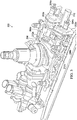
- FIG. 3 shows an isometric view of a drive system 200 that provides maximum system separation and redundancy.
- Drive system 200 include two engine reduction gearboxes 202a, 202b, that are each depicted with an engine connection shaft 204a, 204b. Further, as depicted, the engine reduction gearboxes 202a, 202b are not connected to accessory, such as a generator, a blower, a pump or other accessory that draws power from the engine reduction gearboxes 202a, 202b.
- accessory such as a generator, a blower, a pump or other accessory that draws power from the engine reduction gearboxes 202a, 202b.
- Each of the engine reduction gearboxes 202a, 202b is connected via a shaft 206a, 206b, to the main rotor gear box 208.
- each of the engine connection shaft 204a, 204b provides a single load path from the engines to the main rotor gear box 208.
- each of the engine reduction gearboxes 202a, 202b reduces the speed of rotation from the engine (e.g., up to about 21,000 RPM) to a lower speed (e.g., 6,000 RPM) prior to entering the main rotor gear box 208.
- the main rotor gearbox 208 can be designed to operate with components that are turning at a much lower speed.
- the drive system 200 also connects to the rail rotor via a tail rotor shaft 210.
- Each of the engine connection shaft 204a, 204b can further include, e.g., a brake, a clutch, or other mechanisms for connecting and disconnecting the engine reduction gearboxes 202a, 202b from the main rotor gear box 208.
- Each of the shafts 206a, 206b can connect via clutches 212a, 212b, depicted here on the main rotor gear box 208, however, the skilled artisan will recognize that the clutches 212a, 212b could also be positioned on the engine reduction gearboxes 202a, 202b or even between the engine reduction gearboxes 202a, 202b and the main rotor gear box 208, or combinations of the same.
- the shafts 206a, 206b can be, e.g., a one-piece drive shaft with integral couplings and anti-flail protection.
- the shafts 206a, 206b can be a single material or be a composite material.
- FIG. 4 shows an isometric view of the gears 300, 302, 304, and shaft 306 of the first engine reduction gearbox.
- Input shaft 306 connects to the engine.
- Input shaft 306 is the same for either a right or left engine reduction gearbox.
- Shaft 306 connects to gear 300.
- the gear 300 connects to gear 302, which is an idler gear.
- gear 304 is an output gear, that when connected via gear 302 (idler gear), reduces the speed of rotation from gear 300 (input gear) to gear 304 (output gear).
- Gears 300 through 304 allow for control of speed and torque exiting the engine reduction gearbox.
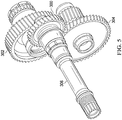
- FIG. 5 shows a contralateral, isometric view of the gears 300, 302, 304, and shaft 306 of the second engine reduction gearbox.
- Input shaft 306 connects to the engine.
- Input shaft 306 is the same for either a right or left engine reduction gearbox.
- Shaft 306 connects to gear 300.
- the gear 300 connects to gear 302, which is an idler gear.
- gear 304 is an output gear, that when connected via gear 302 (idler gear), reduces the speed of rotation from gear 300 (input gear) to gear 304 (output gear).
- Gears 300 through 304 allow for control of speed and torque exiting the engine reduction gearbox.
- each reduction gearbox includes 3 gears, supporting bearings, and an internal oil pump.
- the reduction gearbox has no accessories driven by gearbox (e.g., generators, fans, pumps, etc.).
- the reduction gearbox can also include, e.g., a fuzz burning chip detector at oil pump inlet.
- Another advantage of the present invention includes that each Reduction Gearbox contains its own independent lube system, thereby providing a redundant fail-safe in case of lubrication failure.
- engine input can include a one piece splined shaft 306 piloted at each end.
- each of the independent reduction gearboxes transmit torque from the engines to the main rotor gearbox while reducing speed from, e.g., 21,000, or less, to 6,000, or less, RPM.
- the RGB's transmit torque from the engines to the main rotor gearbox while reducing speed from, e.g., 21,000, or more, to 6,000, or more, RPM. This removes high speed gears and bearings from the main rotor gearbox, and also provide independent power to the main rotor gearbox if either the engine or a reduction gearbox fails. Removing high speed gears from the main rotor gearbox increases the performance of the gearbox in a loss of lube situation.
- FIG. 6 shows a method 600 of providing redundant power to a main rotor gearbox from two or more engines of the present invention.
- a self-contained, independent engine reduction gearbox is connected to each engine is provided in block 602. Redundant, reduced speed is provided to the main rotor gearbox via a shaft using each of the engine reduction gearboxes in block 604.
- each shaft is connected to the main rotor gearbox via a clutch in block 606.
- Each engine reduction gearbox can be separately connected and disconnected from the main rotor gearbox using the clutch.
- a flexible coupling is positioned between one of the engine reduction gearboxes and the main rotor gearbox in block 608.
- one or more clutches are positioned between each input of the main rotor gearbox and its respective engine reduction gearboxes, the shafts, or both in block 610.
- Each shaft can be a one-piece shaft with integral couplings and an anti-flail protection system.
- the two engine reduction gearboxes do not provide power to any accessories.
- At least one gear of each of the two engine reduction gearboxes can connect to the engine via a one-piece splined shaft piloted at each end.
Landscapes
- Engineering & Computer Science (AREA)
- Mechanical Engineering (AREA)
- General Engineering & Computer Science (AREA)
- Aviation & Aerospace Engineering (AREA)
- General Details Of Gearings (AREA)
Claims (9)
- Triebwerks-Untersetzungsgetriebesystem (200), umfassend:mindestens zwei eigenständige, unabhängige Triebwerks-Untersetzungsgetriebe (202a, 202b), die jeweils in der Lage sind, an ein Flugtriebwerk (120a, 120b) angeschlossen zu werden, wobei jedes der Triebwerks-Untersetzungsgetriebe (202a, 202b) eine redundante, reduzierte Drehzahl an ein Hauptrotorgetriebe (114, 208) über eine Rotorwelle (206a, 206b) bereitstellt;wobei jedes der eigenständigen, unabhängigen Triebwerks-Untersetzungsgetriebe (202a, 202b) weiter als Folgendes umfassend definiert ist:ein eigenständiges Schmierstoffsystem;ein internes Ölpumpen-, Ölfilter- und Ölüberwachungssystem;wobei jedes Triebwerks-Untersetzungsgetriebe (202a, 202b) unabhängig von dem Hauptrotorgetriebe (114, 208) angeschlossen und abgetrennt werden kann; undwobei die beiden Triebwerks-Untersetzungsgetriebe (202a, 202b) keinen Strom an irgendwelche Zubehörteile bereitstellen und dadurch gekennzeichnet, das sie weiter ein Antriebsstirnrad (300), ein Laufrad (302), das an dem Antriebsstirnrad (300) angeschlossen ist, ein Abtriebsstirnrad (304), das an dem Laufrad (302) angeschlossen ist, welche die Drehzahl und das Drehmoment steuern, die aus jedem der Triebwerks-Untersetzungsgetriebe austreten, und welche die Drehzahl der Rotation von dem Triebwerk (120a, 120b) vor dem Eintreten in das Hauptrotorgetriebe (114, 208) reduzieren, und Stützlager umfassen.
- Verfahren zum Bereitstellen von redundantem Strom an ein Hauptrotorgetriebe (114, 208) von zwei oder mehrTriebwerken (120a, 120b), umfassend:Anschließen eines eigenständigen, unabhängigen Triebwerks-Untersetzungsgetriebes (202a, 202b) an jedes Triebwerk (120a, 120b); undBereitstellen einer redundanten, reduzierten Drehzahl an das Hauptrotorgetriebe (114, 208) über eine Rotorwelle (206a, 206b) unter Verwendung von jedem der Triebwerks-Untersetzungsgetriebe (202a, 202b); undwobei jedes Triebwerks-Untersetzungsgetriebe (202a, 202b) weiter Folgendes umfasst:ein Antriebsstirnrad (300), ein Laufrad (302), das an dem Antriebsstirnrad (300) angeschlossen ist, und ein Abtriebsstirnrad (304), das an dem Laufrad (302) angeschlossen ist, welche die Drehzahl und das Drehmoment steuern, die aus jedem der Triebwerks-Untersetzungsgetriebe austreten und welche die Drehzahl der Rotation von dem Triebwerk (120a, 120b) vor dem Eintreten in das Hauptrotorgetriebe (114, 208) reduzieren, und Stützlager;ein eigenständiges Schmierstoffsystem;ein internes Ölpumpen-, Ölfilter- und Ölüberwachungssystem;wobei jedes Triebwerks-Untersetzungsgetriebe (202a, 202b) unabhängig von dem Hauptrotorgetriebe (114, 208) angeschlossen und abgetrennt werden kann; undwobei die beiden Triebwerks-Untersetzungsgetriebe (202a, 202b) keinen Strom an irgendwelche Zubehörteile bereitstellen.
- System nach Anspruch 1, wobei jede Rotorwelle (206a, 206b) über eine Kupplung (212a, 212b) an das Hauptrotorgetriebe (114, 208) angeschlossen werden kann, wobei jedes Triebwerks-Untersetzungsgetriebe (202a, 202b) durch die Kupplung (212a, 212b) separat an das Hauptrotorgetriebe (114, 208) angeschlossen und von diesem abgetrennt werden kann; oder
Verfahren nach Anspruch 2, weiter umfassend das Anschließen von jeder Rotorwelle (206a, 206b) an das Hauptrotorgetriebe (114, 208) über eine Kupplung (212a, 212b), wobei jedes Triebwerks-Untersetzungsgetriebe (202a, 202b) unter Verwendung der Kupplung (212a, 212b) separat an das Hauptrotorgetriebe (114, 208) angeschlossen und von diesem abgetrennt werden kann. - System nach Anspruch 1 oder nach einem vorstehenden Anspruch oder Verfahren nach Anspruch 2 oder nach einem vorstehenden Verfahrensanspruch, wobei jede Rotorwelle (206a, 206b) weiter als eine einteilige Rotorwelle mit integrierten Kupplungsverbindungen und einem Ausschlagschutzsystem umfassend definiert ist.
- System nach Anspruch 1 oder nach einem vorstehenden Anspruch oder Verfahren nach Anspruch 2 oder nach einem vorstehenden Verfahrensanspruch, wobei die drei oder mehr Antriebsräder (300, 302, 304) eine Zweizahnradreduktion für eine Reduktion der Triebwerks-Abtriebsdrehzahl auf eine niedrigere Hauptrotorgetriebedrehzahl umfassen.
- System nach Anspruch 1 oder nach einem vorstehenden Anspruch, wobei eine flexible Kupplungsverbindung zwischen einem der Triebwerks-Untersetzungsgetrieben (202a, 202b) und dem Hauptrotorgetriebe (114, 208) positioniert ist; oder
Verfahren nach Anspruch 2 oder nach einem vorstehenden Verfahrensanspruch, weiter umfassend das Positionieren einer flexiblen Kupplungsverbindung zwischen einem der Triebwerks-Untersetzungsgetriebe (202a, 202b) und dem Hauptrotorgetriebe (114, 208). - System nach Anspruch 1 oder nach einem vorstehenden Anspruch, wobei jedes der beiden Triebwerks-Untersetzungsgetriebe (202a, 202b), der Rotorwellen (206a, 206b) oder beide über eine Kupplung (212a, 212b) an dem Hauptrotorgetriebe (114, 208) angeschlossen ist/sind; oder
Verfahren nach Anspruch 2 oder nach einem vorstehenden Verfahrensanspruch, weiter umfassend das Positionieren von einer oder mehreren Kupplungen (212a, 212b) zwischen jedem Antrieb des Hauptrotorgetriebes (114, 208) und seinen entsprechenden Triebwerks-Untersetzungsgetrieben (202a, 202b), den Rotorwellen (206a, 206b) oder beiden. - System nach Anspruch 1 oder nach einem vorstehenden Anspruch oder Verfahren nach Anspruch 2 oder nach einem vorstehenden Verfahrensanspruch, wobei mindestens ein Antriebsstirnrad (300, 302, 304) von jedem der beiden Triebwerks-Untersetzungsgetrieben (202a, 202b) über eine einteilige Keilwelle, die an jedem Ende gelenkt wird, an das Triebwerk (120a, 120b) angeschlossen werden kann.
- System nach Anspruch 1 oder nach einem vorstehenden Anspruch, weiter umfassend:ein Rumpfwerk (102); undein oder mehrere Flugtriebwerke (120a, 120b) in oder an dem Rumpfwerk (102);wobei die Triebwerksdrehzahl vor dem Eintritt in das Hauptrotorgetriebe (114, 208) reduziert wird.
Applications Claiming Priority (3)
| Application Number | Priority Date | Filing Date | Title |
|---|---|---|---|
| US201662399097P | 2016-09-23 | 2016-09-23 | |
| US201662423371P | 2016-11-17 | 2016-11-17 | |
| US15/709,548 US20180087639A1 (en) | 2016-09-23 | 2017-09-20 | High Speed Engine Reduction Gearboxes |
Publications (2)
| Publication Number | Publication Date |
|---|---|
| EP3299288A1 EP3299288A1 (de) | 2018-03-28 |
| EP3299288B1 true EP3299288B1 (de) | 2021-05-26 |
Family
ID=59955461
Family Applications (1)
| Application Number | Title | Priority Date | Filing Date |
|---|---|---|---|
| EP17192688.4A Active EP3299288B1 (de) | 2016-09-23 | 2017-09-22 | Hochgeschwindigkeitsmotoruntersetzungsgetriebe |
Country Status (2)
| Country | Link |
|---|---|
| US (1) | US20180087639A1 (de) |
| EP (1) | EP3299288B1 (de) |
Families Citing this family (1)
| Publication number | Priority date | Publication date | Assignee | Title |
|---|---|---|---|---|
| FR3047471B1 (fr) * | 2016-02-08 | 2018-02-16 | Safran Transmission Systems | Chaine motrice |
Citations (1)
| Publication number | Priority date | Publication date | Assignee | Title |
|---|---|---|---|---|
| EP0023393A1 (de) * | 1979-07-26 | 1981-02-04 | WESTLAND plc | Freilaufvorrichtungen |
Family Cites Families (14)
| Publication number | Priority date | Publication date | Assignee | Title |
|---|---|---|---|---|
| FR1325704A (fr) * | 1962-03-14 | 1963-05-03 | Sud Aviation | Perfectionnement apporté aux boîtes de transmission pour hélicoptères monorotor à plusieurs turbines |
| US5271295A (en) * | 1990-12-12 | 1993-12-21 | Aerospatiale Societe Nationale Industrielle | Mechanism for transmitting power between a driving shaft and two assemblies to be driven |
| JP3029976B2 (ja) * | 1995-01-27 | 2000-04-10 | 株式会社コミュータヘリコプタ先進技術研究所 | ヘリコプタの動力伝達装置 |
| JP3029981B2 (ja) * | 1995-04-27 | 2000-04-10 | 株式会社コミュータヘリコプタ先進技術研究所 | ヘリコプタの動力伝達装置 |
| US6302356B1 (en) * | 1998-08-21 | 2001-10-16 | Rolls-Royce Corporation | Helicopter two stage main reduction gearbox |
| JP3280633B2 (ja) * | 1999-03-24 | 2002-05-13 | 株式会社コミュータヘリコプタ先進技術研究所 | ヘリコプタの動力伝達装置 |
| US6676526B1 (en) * | 2000-10-17 | 2004-01-13 | Bell Helicopter Textron, Inc. | Coupling anti-flail cup |
| US7118328B2 (en) * | 2004-03-12 | 2006-10-10 | Sikorsky Aircraft Corporation | Gearbox mounted force generator |
| US7413142B2 (en) * | 2005-05-31 | 2008-08-19 | Sikorsky Aircraft Corporation | Split torque gearbox for rotary wing aircraft with translational thrust system |
| FR2900386B1 (fr) * | 2006-04-28 | 2008-06-20 | Eurocopter France | Installation motrice pour aeronef a voilure tournante |
| ATE533929T1 (de) * | 2007-01-19 | 2011-12-15 | Sikorsky Aircraft Corp | Schmiersystem mit verlängertem lol-betrieb (lol - loss of lubricant) |
| US8740565B2 (en) | 2011-08-12 | 2014-06-03 | Hamilton Sundstrand Corporation | Modular counter rotating propeller system |
| US10850863B2 (en) * | 2014-03-04 | 2020-12-01 | Pratt & Whitney Canada Corp. | System and method for operating a multi-engine aircraft in an auxiliary power unit mode |
| US9611789B2 (en) | 2015-03-27 | 2017-04-04 | Pratt & Whitney Canada Corp. | Reduction gearbox for a gas turbine engine |
-
2017
- 2017-09-20 US US15/709,548 patent/US20180087639A1/en not_active Abandoned
- 2017-09-22 EP EP17192688.4A patent/EP3299288B1/de active Active
Patent Citations (1)
| Publication number | Priority date | Publication date | Assignee | Title |
|---|---|---|---|---|
| EP0023393A1 (de) * | 1979-07-26 | 1981-02-04 | WESTLAND plc | Freilaufvorrichtungen |
Non-Patent Citations (3)
| Title |
|---|
| ANONYMOUS: "CH-53E New Ep's Flashcards", 1 November 2016 (2016-11-01), XP055591788, Retrieved from the Internet <URL:https://www.flashcardmachine.com/ch-53eneweps.html> [retrieved on 20190524] * |
| ANONYMOUS: "Sikorsky Archives | S-65/H-53A/D Sea Stallion/ H-53E Super Stallion", 31 July 2013 (2013-07-31), XP055591783, Retrieved from the Internet <URL:https://www.sikorskyarchives.com/S-65H-53D%20SEA%20STALLION.php> [retrieved on 20190524] * |
| XP055592953 * |
Also Published As
| Publication number | Publication date |
|---|---|
| EP3299288A1 (de) | 2018-03-28 |
| US20180087639A1 (en) | 2018-03-29 |
Similar Documents
| Publication | Publication Date | Title |
|---|---|---|
| EP3299286B1 (de) | Flugzeugantriebssystem | |
| EP3299283B1 (de) | Druckloses hilfsgetriebe | |
| US7918146B2 (en) | Multi-path rotary wing aircraft gearbox | |
| US7168913B2 (en) | Twin-spool turbojet with means for driving ancillary machines | |
| CN101501367B (zh) | 用于带平移推进系统的旋翼飞机的分流转矩式变速箱 | |
| US5823470A (en) | Split torque proprotor transmission | |
| US20050011307A1 (en) | Split-torque gear box | |
| US12030662B2 (en) | Propulsion system for a helicopter | |
| US20190257249A1 (en) | Engine accessory drives systems and methods | |
| US10006361B2 (en) | Multi-fan engine with an enhanced power transmission | |
| EP3038906B1 (de) | Gewichtsreduziertes antriebsgetriebe | |
| EP3567282A1 (de) | Verwendung der dosierbohrung im ummantelung eines spritzgeschmierten getriebes zum ausgeben von schmierstoff im getriebe | |
| US20180087420A1 (en) | Oil-level sensor for a gearbox | |
| US10385959B2 (en) | Flange-mounted ring gear for improved heat management | |
| US6443035B1 (en) | Hybrid power input quill for transmissions | |
| US10724625B2 (en) | Torsionally compliant geartrain carrier assembly | |
| US11498670B2 (en) | Coaxial split torque gear box | |
| EP3299676B1 (de) | Angeflanschtes hohlrad für verbesserte wärmeverwaltung | |
| EP3299288A1 (de) | Hochgeschwindigkeitsmotoruntersetzungsgetriebe | |
| EP3564558A1 (de) | Überbrückungselement für ungeregelte getriebe | |
| RU2749965C1 (ru) | Редуктор вертолета | |
| US20250122841A1 (en) | Lubrication system for aircraft powerplant and clutch system | |
| EP3564120A1 (de) | Getriebefüllanordnung |
Legal Events
| Date | Code | Title | Description |
|---|---|---|---|
| PUAI | Public reference made under article 153(3) epc to a published international application that has entered the european phase |
Free format text: ORIGINAL CODE: 0009012 |
|
| STAA | Information on the status of an ep patent application or granted ep patent |
Free format text: STATUS: EXAMINATION IS IN PROGRESS |
|
| 17P | Request for examination filed |
Effective date: 20170922 |
|
| AK | Designated contracting states |
Kind code of ref document: A1 Designated state(s): AL AT BE BG CH CY CZ DE DK EE ES FI FR GB GR HR HU IE IS IT LI LT LU LV MC MK MT NL NO PL PT RO RS SE SI SK SM TR |
|
| AX | Request for extension of the european patent |
Extension state: BA ME |
|
| REG | Reference to a national code |
Ref country code: DE Ref legal event code: R079 Ref document number: 602017039170 Country of ref document: DE Free format text: PREVIOUS MAIN CLASS: B64C0027140000 Ipc: B64D0035080000 |
|
| GRAP | Despatch of communication of intention to grant a patent |
Free format text: ORIGINAL CODE: EPIDOSNIGR1 |
|
| STAA | Information on the status of an ep patent application or granted ep patent |
Free format text: STATUS: GRANT OF PATENT IS INTENDED |
|
| RIC1 | Information provided on ipc code assigned before grant |
Ipc: B64D 35/08 20060101AFI20201009BHEP Ipc: B64C 27/14 20060101ALI20201009BHEP |
|
| INTG | Intention to grant announced |
Effective date: 20201106 |
|
| RIN1 | Information on inventor provided before grant (corrected) |
Inventor name: SPELLER JR., CHARLES HUBERT Inventor name: POSTER, SCOTT DAVID Inventor name: RILEY, WALTER Inventor name: COPE, GARY |
|
| GRAJ | Information related to disapproval of communication of intention to grant by the applicant or resumption of examination proceedings by the epo deleted |
Free format text: ORIGINAL CODE: EPIDOSDIGR1 |
|
| STAA | Information on the status of an ep patent application or granted ep patent |
Free format text: STATUS: EXAMINATION IS IN PROGRESS |
|
| GRAJ | Information related to disapproval of communication of intention to grant by the applicant or resumption of examination proceedings by the epo deleted |
Free format text: ORIGINAL CODE: EPIDOSDIGR1 |
|
| STAA | Information on the status of an ep patent application or granted ep patent |
Free format text: STATUS: GRANT OF PATENT IS INTENDED |
|
| GRAP | Despatch of communication of intention to grant a patent |
Free format text: ORIGINAL CODE: EPIDOSNIGR1 |
|
| INTC | Intention to grant announced (deleted) | ||
| INTG | Intention to grant announced |
Effective date: 20210217 |
|
| GRAS | Grant fee paid |
Free format text: ORIGINAL CODE: EPIDOSNIGR3 |
|
| GRAA | (expected) grant |
Free format text: ORIGINAL CODE: 0009210 |
|
| STAA | Information on the status of an ep patent application or granted ep patent |
Free format text: STATUS: THE PATENT HAS BEEN GRANTED |
|
| AK | Designated contracting states |
Kind code of ref document: B1 Designated state(s): AL AT BE BG CH CY CZ DE DK EE ES FI FR GB GR HR HU IE IS IT LI LT LU LV MC MK MT NL NO PL PT RO RS SE SI SK SM TR |
|
| REG | Reference to a national code |
Ref country code: GB Ref legal event code: FG4D |
|
| REG | Reference to a national code |
Ref country code: CH Ref legal event code: EP |
|
| REG | Reference to a national code |
Ref country code: AT Ref legal event code: REF Ref document number: 1396012 Country of ref document: AT Kind code of ref document: T Effective date: 20210615 |
|
| REG | Reference to a national code |
Ref country code: DE Ref legal event code: R096 Ref document number: 602017039170 Country of ref document: DE |
|
| REG | Reference to a national code |
Ref country code: IE Ref legal event code: FG4D |
|
| REG | Reference to a national code |
Ref country code: LT Ref legal event code: MG9D |
|
| REG | Reference to a national code |
Ref country code: AT Ref legal event code: MK05 Ref document number: 1396012 Country of ref document: AT Kind code of ref document: T Effective date: 20210526 |
|
| PG25 | Lapsed in a contracting state [announced via postgrant information from national office to epo] |
Ref country code: AT Free format text: LAPSE BECAUSE OF FAILURE TO SUBMIT A TRANSLATION OF THE DESCRIPTION OR TO PAY THE FEE WITHIN THE PRESCRIBED TIME-LIMIT Effective date: 20210526 Ref country code: BG Free format text: LAPSE BECAUSE OF FAILURE TO SUBMIT A TRANSLATION OF THE DESCRIPTION OR TO PAY THE FEE WITHIN THE PRESCRIBED TIME-LIMIT Effective date: 20210826 Ref country code: HR Free format text: LAPSE BECAUSE OF FAILURE TO SUBMIT A TRANSLATION OF THE DESCRIPTION OR TO PAY THE FEE WITHIN THE PRESCRIBED TIME-LIMIT Effective date: 20210526 Ref country code: LT Free format text: LAPSE BECAUSE OF FAILURE TO SUBMIT A TRANSLATION OF THE DESCRIPTION OR TO PAY THE FEE WITHIN THE PRESCRIBED TIME-LIMIT Effective date: 20210526 Ref country code: FI Free format text: LAPSE BECAUSE OF FAILURE TO SUBMIT A TRANSLATION OF THE DESCRIPTION OR TO PAY THE FEE WITHIN THE PRESCRIBED TIME-LIMIT Effective date: 20210526 |
|
| REG | Reference to a national code |
Ref country code: NL Ref legal event code: MP Effective date: 20210526 |
|
| PG25 | Lapsed in a contracting state [announced via postgrant information from national office to epo] |
Ref country code: GR Free format text: LAPSE BECAUSE OF FAILURE TO SUBMIT A TRANSLATION OF THE DESCRIPTION OR TO PAY THE FEE WITHIN THE PRESCRIBED TIME-LIMIT Effective date: 20210827 Ref country code: LV Free format text: LAPSE BECAUSE OF FAILURE TO SUBMIT A TRANSLATION OF THE DESCRIPTION OR TO PAY THE FEE WITHIN THE PRESCRIBED TIME-LIMIT Effective date: 20210526 Ref country code: IS Free format text: LAPSE BECAUSE OF FAILURE TO SUBMIT A TRANSLATION OF THE DESCRIPTION OR TO PAY THE FEE WITHIN THE PRESCRIBED TIME-LIMIT Effective date: 20210926 Ref country code: PT Free format text: LAPSE BECAUSE OF FAILURE TO SUBMIT A TRANSLATION OF THE DESCRIPTION OR TO PAY THE FEE WITHIN THE PRESCRIBED TIME-LIMIT Effective date: 20210927 Ref country code: PL Free format text: LAPSE BECAUSE OF FAILURE TO SUBMIT A TRANSLATION OF THE DESCRIPTION OR TO PAY THE FEE WITHIN THE PRESCRIBED TIME-LIMIT Effective date: 20210526 Ref country code: NO Free format text: LAPSE BECAUSE OF FAILURE TO SUBMIT A TRANSLATION OF THE DESCRIPTION OR TO PAY THE FEE WITHIN THE PRESCRIBED TIME-LIMIT Effective date: 20210826 Ref country code: SE Free format text: LAPSE BECAUSE OF FAILURE TO SUBMIT A TRANSLATION OF THE DESCRIPTION OR TO PAY THE FEE WITHIN THE PRESCRIBED TIME-LIMIT Effective date: 20210526 Ref country code: RS Free format text: LAPSE BECAUSE OF FAILURE TO SUBMIT A TRANSLATION OF THE DESCRIPTION OR TO PAY THE FEE WITHIN THE PRESCRIBED TIME-LIMIT Effective date: 20210526 |
|
| PG25 | Lapsed in a contracting state [announced via postgrant information from national office to epo] |
Ref country code: NL Free format text: LAPSE BECAUSE OF FAILURE TO SUBMIT A TRANSLATION OF THE DESCRIPTION OR TO PAY THE FEE WITHIN THE PRESCRIBED TIME-LIMIT Effective date: 20210526 |
|
| PG25 | Lapsed in a contracting state [announced via postgrant information from national office to epo] |
Ref country code: CZ Free format text: LAPSE BECAUSE OF FAILURE TO SUBMIT A TRANSLATION OF THE DESCRIPTION OR TO PAY THE FEE WITHIN THE PRESCRIBED TIME-LIMIT Effective date: 20210526 Ref country code: DK Free format text: LAPSE BECAUSE OF FAILURE TO SUBMIT A TRANSLATION OF THE DESCRIPTION OR TO PAY THE FEE WITHIN THE PRESCRIBED TIME-LIMIT Effective date: 20210526 Ref country code: EE Free format text: LAPSE BECAUSE OF FAILURE TO SUBMIT A TRANSLATION OF THE DESCRIPTION OR TO PAY THE FEE WITHIN THE PRESCRIBED TIME-LIMIT Effective date: 20210526 Ref country code: RO Free format text: LAPSE BECAUSE OF FAILURE TO SUBMIT A TRANSLATION OF THE DESCRIPTION OR TO PAY THE FEE WITHIN THE PRESCRIBED TIME-LIMIT Effective date: 20210526 Ref country code: ES Free format text: LAPSE BECAUSE OF FAILURE TO SUBMIT A TRANSLATION OF THE DESCRIPTION OR TO PAY THE FEE WITHIN THE PRESCRIBED TIME-LIMIT Effective date: 20210526 Ref country code: SM Free format text: LAPSE BECAUSE OF FAILURE TO SUBMIT A TRANSLATION OF THE DESCRIPTION OR TO PAY THE FEE WITHIN THE PRESCRIBED TIME-LIMIT Effective date: 20210526 Ref country code: SK Free format text: LAPSE BECAUSE OF FAILURE TO SUBMIT A TRANSLATION OF THE DESCRIPTION OR TO PAY THE FEE WITHIN THE PRESCRIBED TIME-LIMIT Effective date: 20210526 |
|
| REG | Reference to a national code |
Ref country code: DE Ref legal event code: R097 Ref document number: 602017039170 Country of ref document: DE |
|
| PLBE | No opposition filed within time limit |
Free format text: ORIGINAL CODE: 0009261 |
|
| STAA | Information on the status of an ep patent application or granted ep patent |
Free format text: STATUS: NO OPPOSITION FILED WITHIN TIME LIMIT |
|
| 26N | No opposition filed |
Effective date: 20220301 |
|
| REG | Reference to a national code |
Ref country code: CH Ref legal event code: PL |
|
| REG | Reference to a national code |
Ref country code: BE Ref legal event code: MM Effective date: 20210930 |
|
| PG25 | Lapsed in a contracting state [announced via postgrant information from national office to epo] |
Ref country code: IS Free format text: LAPSE BECAUSE OF FAILURE TO SUBMIT A TRANSLATION OF THE DESCRIPTION OR TO PAY THE FEE WITHIN THE PRESCRIBED TIME-LIMIT Effective date: 20210926 Ref country code: MC Free format text: LAPSE BECAUSE OF FAILURE TO SUBMIT A TRANSLATION OF THE DESCRIPTION OR TO PAY THE FEE WITHIN THE PRESCRIBED TIME-LIMIT Effective date: 20210526 Ref country code: AL Free format text: LAPSE BECAUSE OF FAILURE TO SUBMIT A TRANSLATION OF THE DESCRIPTION OR TO PAY THE FEE WITHIN THE PRESCRIBED TIME-LIMIT Effective date: 20210526 |
|
| PG25 | Lapsed in a contracting state [announced via postgrant information from national office to epo] |
Ref country code: LU Free format text: LAPSE BECAUSE OF NON-PAYMENT OF DUE FEES Effective date: 20210922 Ref country code: IE Free format text: LAPSE BECAUSE OF NON-PAYMENT OF DUE FEES Effective date: 20210922 Ref country code: BE Free format text: LAPSE BECAUSE OF NON-PAYMENT OF DUE FEES Effective date: 20210930 |
|
| PG25 | Lapsed in a contracting state [announced via postgrant information from national office to epo] |
Ref country code: LI Free format text: LAPSE BECAUSE OF NON-PAYMENT OF DUE FEES Effective date: 20210930 Ref country code: CH Free format text: LAPSE BECAUSE OF NON-PAYMENT OF DUE FEES Effective date: 20210930 |
|
| PG25 | Lapsed in a contracting state [announced via postgrant information from national office to epo] |
Ref country code: HU Free format text: LAPSE BECAUSE OF FAILURE TO SUBMIT A TRANSLATION OF THE DESCRIPTION OR TO PAY THE FEE WITHIN THE PRESCRIBED TIME-LIMIT; INVALID AB INITIO Effective date: 20170922 |
|
| PG25 | Lapsed in a contracting state [announced via postgrant information from national office to epo] |
Ref country code: CY Free format text: LAPSE BECAUSE OF FAILURE TO SUBMIT A TRANSLATION OF THE DESCRIPTION OR TO PAY THE FEE WITHIN THE PRESCRIBED TIME-LIMIT Effective date: 20210526 |
|
| P01 | Opt-out of the competence of the unified patent court (upc) registered |
Effective date: 20230602 |
|
| PG25 | Lapsed in a contracting state [announced via postgrant information from national office to epo] |
Ref country code: MK Free format text: LAPSE BECAUSE OF FAILURE TO SUBMIT A TRANSLATION OF THE DESCRIPTION OR TO PAY THE FEE WITHIN THE PRESCRIBED TIME-LIMIT Effective date: 20210526 |
|
| PG25 | Lapsed in a contracting state [announced via postgrant information from national office to epo] |
Ref country code: TR Free format text: LAPSE BECAUSE OF FAILURE TO SUBMIT A TRANSLATION OF THE DESCRIPTION OR TO PAY THE FEE WITHIN THE PRESCRIBED TIME-LIMIT Effective date: 20210526 |
|
| PG25 | Lapsed in a contracting state [announced via postgrant information from national office to epo] |
Ref country code: MT Free format text: LAPSE BECAUSE OF FAILURE TO SUBMIT A TRANSLATION OF THE DESCRIPTION OR TO PAY THE FEE WITHIN THE PRESCRIBED TIME-LIMIT Effective date: 20210526 |
|
| PGFP | Annual fee paid to national office [announced via postgrant information from national office to epo] |
Ref country code: DE Payment date: 20250929 Year of fee payment: 9 |
|
| PGFP | Annual fee paid to national office [announced via postgrant information from national office to epo] |
Ref country code: IT Payment date: 20250919 Year of fee payment: 9 |
|
| PGFP | Annual fee paid to national office [announced via postgrant information from national office to epo] |
Ref country code: GB Payment date: 20250929 Year of fee payment: 9 |
|
| PGFP | Annual fee paid to national office [announced via postgrant information from national office to epo] |
Ref country code: FR Payment date: 20250925 Year of fee payment: 9 |