EP3299285A1 - Active thermal management for fire-tolerant drive systems - Google Patents
Active thermal management for fire-tolerant drive systems Download PDFInfo
- Publication number
- EP3299285A1 EP3299285A1 EP17192697.5A EP17192697A EP3299285A1 EP 3299285 A1 EP3299285 A1 EP 3299285A1 EP 17192697 A EP17192697 A EP 17192697A EP 3299285 A1 EP3299285 A1 EP 3299285A1
- Authority
- EP
- European Patent Office
- Prior art keywords
- drive shaft
- impellers
- fans
- baffles
- shaft
- Prior art date
- Legal status (The legal status is an assumption and is not a legal conclusion. Google has not performed a legal analysis and makes no representation as to the accuracy of the status listed.)
- Granted
Links
Images



Classifications
-
- F—MECHANICAL ENGINEERING; LIGHTING; HEATING; WEAPONS; BLASTING
- F16—ENGINEERING ELEMENTS AND UNITS; GENERAL MEASURES FOR PRODUCING AND MAINTAINING EFFECTIVE FUNCTIONING OF MACHINES OR INSTALLATIONS; THERMAL INSULATION IN GENERAL
- F16C—SHAFTS; FLEXIBLE SHAFTS; ELEMENTS OR CRANKSHAFT MECHANISMS; ROTARY BODIES OTHER THAN GEARING ELEMENTS; BEARINGS
- F16C3/00—Shafts; Axles; Cranks; Eccentrics
- F16C3/04—Crankshafts, eccentric-shafts; Cranks, eccentrics
- F16C3/06—Crankshafts
- F16C3/16—Features relating to cooling
-
- B—PERFORMING OPERATIONS; TRANSPORTING
- B64—AIRCRAFT; AVIATION; COSMONAUTICS
- B64C—AEROPLANES; HELICOPTERS
- B64C27/00—Rotorcraft; Rotors peculiar thereto
- B64C27/04—Helicopters
- B64C27/12—Rotor drives
- B64C27/14—Direct drive between power plant and rotor hub
-
- B—PERFORMING OPERATIONS; TRANSPORTING
- B64—AIRCRAFT; AVIATION; COSMONAUTICS
- B64C—AEROPLANES; HELICOPTERS
- B64C27/00—Rotorcraft; Rotors peculiar thereto
- B64C27/04—Helicopters
- B64C27/12—Rotor drives
-
- B—PERFORMING OPERATIONS; TRANSPORTING
- B64—AIRCRAFT; AVIATION; COSMONAUTICS
- B64C—AEROPLANES; HELICOPTERS
- B64C27/00—Rotorcraft; Rotors peculiar thereto
- B64C27/82—Rotorcraft; Rotors peculiar thereto characterised by the provision of an auxiliary rotor or fluid-jet device for counter-balancing lifting rotor torque or changing direction of rotorcraft
-
- B—PERFORMING OPERATIONS; TRANSPORTING
- B64—AIRCRAFT; AVIATION; COSMONAUTICS
- B64D—EQUIPMENT FOR FITTING IN OR TO AIRCRAFT; FLIGHT SUITS; PARACHUTES; ARRANGEMENT OR MOUNTING OF POWER PLANTS OR PROPULSION TRANSMISSIONS IN AIRCRAFT
- B64D35/00—Transmitting power from power plants to propellers or rotors; Arrangements of transmissions
-
- B—PERFORMING OPERATIONS; TRANSPORTING
- B64—AIRCRAFT; AVIATION; COSMONAUTICS
- B64D—EQUIPMENT FOR FITTING IN OR TO AIRCRAFT; FLIGHT SUITS; PARACHUTES; ARRANGEMENT OR MOUNTING OF POWER PLANTS OR PROPULSION TRANSMISSIONS IN AIRCRAFT
- B64D45/00—Aircraft indicators or protectors not otherwise provided for
-
- F—MECHANICAL ENGINEERING; LIGHTING; HEATING; WEAPONS; BLASTING
- F16—ENGINEERING ELEMENTS AND UNITS; GENERAL MEASURES FOR PRODUCING AND MAINTAINING EFFECTIVE FUNCTIONING OF MACHINES OR INSTALLATIONS; THERMAL INSULATION IN GENERAL
- F16C—SHAFTS; FLEXIBLE SHAFTS; ELEMENTS OR CRANKSHAFT MECHANISMS; ROTARY BODIES OTHER THAN GEARING ELEMENTS; BEARINGS
- F16C3/00—Shafts; Axles; Cranks; Eccentrics
- F16C3/02—Shafts; Axles
-
- F—MECHANICAL ENGINEERING; LIGHTING; HEATING; WEAPONS; BLASTING
- F16—ENGINEERING ELEMENTS AND UNITS; GENERAL MEASURES FOR PRODUCING AND MAINTAINING EFFECTIVE FUNCTIONING OF MACHINES OR INSTALLATIONS; THERMAL INSULATION IN GENERAL
- F16C—SHAFTS; FLEXIBLE SHAFTS; ELEMENTS OR CRANKSHAFT MECHANISMS; ROTARY BODIES OTHER THAN GEARING ELEMENTS; BEARINGS
- F16C3/00—Shafts; Axles; Cranks; Eccentrics
- F16C3/02—Shafts; Axles
- F16C3/026—Shafts made of fibre reinforced resin
-
- B—PERFORMING OPERATIONS; TRANSPORTING
- B64—AIRCRAFT; AVIATION; COSMONAUTICS
- B64D—EQUIPMENT FOR FITTING IN OR TO AIRCRAFT; FLIGHT SUITS; PARACHUTES; ARRANGEMENT OR MOUNTING OF POWER PLANTS OR PROPULSION TRANSMISSIONS IN AIRCRAFT
- B64D45/00—Aircraft indicators or protectors not otherwise provided for
- B64D2045/009—Fire detection or protection; Erosion protection, e.g. from airborne particles
-
- F—MECHANICAL ENGINEERING; LIGHTING; HEATING; WEAPONS; BLASTING
- F16—ENGINEERING ELEMENTS AND UNITS; GENERAL MEASURES FOR PRODUCING AND MAINTAINING EFFECTIVE FUNCTIONING OF MACHINES OR INSTALLATIONS; THERMAL INSULATION IN GENERAL
- F16C—SHAFTS; FLEXIBLE SHAFTS; ELEMENTS OR CRANKSHAFT MECHANISMS; ROTARY BODIES OTHER THAN GEARING ELEMENTS; BEARINGS
- F16C2326/00—Articles relating to transporting
- F16C2326/01—Parts of vehicles in general
- F16C2326/06—Drive shafts
-
- F—MECHANICAL ENGINEERING; LIGHTING; HEATING; WEAPONS; BLASTING
- F16—ENGINEERING ELEMENTS AND UNITS; GENERAL MEASURES FOR PRODUCING AND MAINTAINING EFFECTIVE FUNCTIONING OF MACHINES OR INSTALLATIONS; THERMAL INSULATION IN GENERAL
- F16C—SHAFTS; FLEXIBLE SHAFTS; ELEMENTS OR CRANKSHAFT MECHANISMS; ROTARY BODIES OTHER THAN GEARING ELEMENTS; BEARINGS
- F16C2326/00—Articles relating to transporting
- F16C2326/43—Aeroplanes; Helicopters
-
- F—MECHANICAL ENGINEERING; LIGHTING; HEATING; WEAPONS; BLASTING
- F16—ENGINEERING ELEMENTS AND UNITS; GENERAL MEASURES FOR PRODUCING AND MAINTAINING EFFECTIVE FUNCTIONING OF MACHINES OR INSTALLATIONS; THERMAL INSULATION IN GENERAL
- F16D—COUPLINGS FOR TRANSMITTING ROTATION; CLUTCHES; BRAKES
- F16D2300/00—Special features for couplings or clutches
- F16D2300/02—Overheat protection, i.e. means for protection against overheating
- F16D2300/021—Cooling features not provided for in group F16D13/72 or F16D25/123, e.g. heat transfer details
- F16D2300/0212—Air cooling
-
- F—MECHANICAL ENGINEERING; LIGHTING; HEATING; WEAPONS; BLASTING
- F16—ENGINEERING ELEMENTS AND UNITS; GENERAL MEASURES FOR PRODUCING AND MAINTAINING EFFECTIVE FUNCTIONING OF MACHINES OR INSTALLATIONS; THERMAL INSULATION IN GENERAL
- F16H—GEARING
- F16H57/00—General details of gearing
- F16H57/04—Features relating to lubrication or cooling or heating
- F16H57/0412—Cooling or heating; Control of temperature
- F16H57/0415—Air cooling or ventilation; Heat exchangers; Thermal insulations
- F16H57/0416—Air cooling or ventilation
Definitions
- the present invention relates in general to the field of thermal management of drive systems, and more particularly, to a novel system for active thermal management for fire-tolerant drive systems for use in an aircraft.
- a rotorcraft may include one or more rotor systems.
- a rotorcraft rotor system is a main rotor system.
- a main rotor system may generate aerodynamic lift to support the weight of the rotorcraft in flight and thrust to counteract aerodynamic drag and move the rotorcraft in forward flight.
- a tail rotor system is another example of a rotorcraft rotor system.
- a tail rotor system may generate thrust in the same direction as the main rotor system's rotation to counter the torque effect created by the main rotor system.
- a tail rotor drive system requires a mechanical coupling to an engine and transmission.
- a drive shaft of a tail rotor drive system is vulnerable to damage. If a drive shaft is damaged in flight, the tail rotor's operation may be compromised, reducing or eliminating a pilot's ability to control the rotorcraft and placing the craft and its crew and occupants in danger.
- the present invention includes a thermal management system, including a drive shaft; one or more fans or impellers in fluid communication with at least a portion of the drive shaft; and one or more air management baffles configured to direct air flow between the impeller and the at least a portion of the drive shaft.
- the portion in fluid communication with the one or more fans or impellers is at least one of a proximate portion, a distal portion, or an intermediate portion of the drive shaft.
- the one or more fans or impellers are connected to the drive shaft, or are powered independently of the drive shaft.
- the drive shaft is a tail rotor drive shaft, a main rotor shaft, a proprotor shaft, a propeller shaft, or a wind-turbine shaft.
- the system further includes the one or more air management baffles that surround at least a portion of the drive shaft.
- the one or more air management baffles include a rigid material, a flexible material, or combinations thereof.
- at least a portion of the draft shaft includes a composite material.
- the system further includes insulation positioned about at least a portion of the drive shaft.
- the system further includes the insulation surrounds the portion of the drive shaft adjacent an engine compartment.
- the insulation surrounds at least a portion of the one or more air management baffles.
- the present invention includes a method of managing the thermal condition of a drive system, including placing one or more fans or impellers in fluid communication with a portion of a drive shaft; and configuring one or more air management baffles to direct air between the one or more fans or impellers and the drive shaft.
- the method further includes placing the one or more fans or impellers in fluid communication with at least one of a proximate portion, a distal portion, or an intermediate portion of the drive shaft.
- the method further includes connecting the one or more fans or impellers to the drive shaft.
- the method further includes powering the one or more fans or impellers independently from the drive shaft.
- the drive shaft is a tail rotor drive shaft, a main rotor drive shaft, a proprotor drive shaft, a propeller drive shaft, or a wind-turbine drive shaft.
- the method further includes configuring one or more air management baffles to surround at least a portion of the drive shaft.
- the one or more air management baffles include a rigid material, a flexible material, or combinations thereof.
- the drive shaft, the one or more fans or impellers, or both include a composite material.
- the method further includes positioning insulation about at least a portion of the drive shaft.
- the method further includes positioning insulation about at least a portion of the drive shaft adjacent to an engine compartment.
- the present invention includes a rotorcraft including a fuselage; an engine compartment coupled to the fuselage; an engine coupled to the engine compartment and disposed within the engine compartment; a transmission coupled to the fuselage; the engine coupled to the transmission; a drive shaft coupled to the transmission; one or more fans or impellers in fluid communication with at least a portion of the drive shaft; and one or more air management baffles configured to direct air flow between the one or more fans or impellers and the at least a portion of the drive shaft.
- the rotorcraft further includes insulation between the tail rotor drive shaft and the engine compartment.
- the present invention is directed to a thermal management system for drive shafts that include one or more fans or impellers in fluid communication with at least a portion of the drive shaft.
- the thermal management system may also include one or more air management baffles configured to direct air flow between the impeller and the drive shaft.
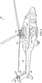
- FIG. 1 shows an aircraft 100 in accordance with a preferred embodiment of the present application.
- aircraft 100 is a helicopter having a fuselage 102 and a rotor system 104 carried thereon.
- a plurality of rotor blades 106 is operably associated with a rotor system 104 for creating flight.
- a tail boom 108 is depicted that further includes tail rotor 110.
- FIG. 2 shows a partial cross-section isometric view of aircraft 100 that includes additional detail of an embodiment of the present invention.
- Aircraft 100 further includes a rotor mast 112, which is connected to the main transmission 114.
- the main transmission 114 is connected to one or more accessory gear boxes 116.
- the engine compartment 118 contains engine 120, and the main transmission 114 is connected to engine 120.
- a tail rotor drive shaft 122 transmits mechanical rotation to the tail rotor gear box 124, which is connected via tail rotor drive shaft 126, via intermediate gear box 128.
- FIGS. 3A , 3B, and 3C show cross-sectional views of portions of an active thermal management system 130 that illustrate various embodiments of the present invention.
- FIG. 3A shows a cross-sectional view of the length of tail rotor drive shaft 122.
- the tail rotor drive shaft 122 may be composed of a metal or composite material that is resistant to heat.
- Tail rotor drive shaft 122 can be a single shaft or can be made from various connected shafts.
- the tail rotor drive shaft 122 has, in relation to the front of the aircraft, proximate portion 132; a portion distant from the front of the aircraft, distal portion 136; and one or more intermediate portions 134 between proximate portion 132 and distal portion 136, an engine compartment 118 and an engine 120.
- One or more fans or impellers 138a, 138b, 138c are placed in fluid communication with tail rotor drive shaft 122.
- One or more fans or impellers 138a, 138b, 138c may be connected to the proximate portion 132, the intermediate portion 134, the distal portion 136, or any combination thereof, of tail rotor drive shaft 122 so that the fans or impellers 138a, 138b, 138c rotate when the tail rotor drive shaft 122 rotates, causing air to flow across the surface of tail rotor drive shaft 122.
- the fans or impellers 138a, 138b, 138c may be directly connected to the tail rotor drive shaft 122 or powered independently of the tail rotor drive shaft 122.
- the fans or impellers 138a, 138b, 138c are shown fixed to a variety of locations on or about tail rotor drive shaft 122 to illustrate a number of possible location(s) for the fans or impellers 138a, 138b, 138c.
- One or more air management baffles 140 may also be included and configured to direct air moved to, or from, the one or more fans or impellers 138a, 138b, 138c, over the tail rotor drive shaft 122 to cool it.
- Insulation 142 may also be included and is positioned to protect the tail rotor drive shaft 122 from heat or fire in the engine compartment 118, which insulation 142 may also be cylindrical and surround the entire tail rotor drive shaft 122.
- Insulation 142 may be positioned near the tail rotor drive shaft 122, the air management baffle 140, or both between the engine compartment 118 and the tail rotor drive shaft 122. Insulation 142 will generally be positioned to surround tail rotor drive shaft 122 or air management baffle 140 or both, and may be rigid, flexible or combinations thereof.
- FIG. 3B shows a cross-sectional view of the distal portion 136 of tail rotor drive shaft 122 with fan or impeller 138c.
- fan or impeller 138c is within the air management baffle 140 compartment of distal portion 136, with air management baffle 140 surrounding distal portion 136, and within insulation 142 positioned at distal portion 136 as described in FIG. 3A .
- a similar configuration may be used at the proximal end of the tail rotor drive shaft 122.
- FIG. 3C shows a cross-sectional view of the distal portion 136 of tail rotor drive shaft 122 with fan or impeller 138c fixed outside the distal portion 136 and the air management baffle 140 compartment. Insulation 142 is positioned near distal portion 136 as described in FIG. 3A . A similar configuration may be used at the proximal end of the tail rotor drive shaft 122.
- an isometric cut-away view of a portion of an active thermal management system 130 illustrates an embodiment of the present invention.
- distal portion 136 of tail rotor drive shaft 122 is surrounded by one or more air management baffles 140, in which a fan or impeller 138c is fixed to the distal portion 136 of tail rotor drive shaft 122, such that they turn together to provide air flow to cool tail rotor drive shaft 122.
- Insulation 142 is around the tail rotor drive shaft 122 and air management baffle 140.
- Similar arrangements of component elements, not shown, may be disposed at the proximate portion 132, or the intermediate portion 134, or any combination thereof, of tail rotor drive shaft 122.
- the insulation 142 would also serve to protect the tail rotor drive shaft 122 to ensure continued safe flight at least for period of time sufficient for a safe landing.
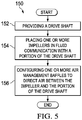
- a flowchart 150 of a method for managing the thermal condition of a drive system illustrates an embodiment of the present invention.
- the method 150 begins at block 152 by providing a drive shaft and at block 154 by placing one or more fans or impellers in fluid communication with a portion of a drive shaft such as tail rotor drive shaft.
- the method 150 concludes at block 156 by configuring one or more air management baffles to direct air between the one or more fans or impellers and the drive shaft. If the fans or impellers are driven separately from the tail rotor drive shaft
- novel active thermal management system 130 of the present invention provides independent methods of rendering a drive system tolerant to the excessive heat that may occur in an engine compartment: use of fire-tolerant composite material for a drive shaft such as tail rotor drive shaft 122; one or more fans or impellers 138a, 138b, and/or 138c connected to the drive shaft to move air over the shaft through one or air management baffles 140; and insulation 142 around the drive shaft.
- Non-limiting examples of composite materials for use with the drive shafts include, e.g., metals, carbon fiber, metal-carbon fiber, fiber reinforcement unidirectional layers embedded in the thermoplastic polymer, or combinations thereof.
- the composite drive shafts may be a composite tube that is a braided fiber and resin transfer molded component. Such components are typically more damage tolerant and have a higher ballistic survivability.
- the braided fiber may be either a two-dimensional or a three-dimensional braided fiber.
- the composite shaft may also be manufactured by filament winding, fiber placement, or any other processes that are deemed appropriate.
- the drive shafts can also include end adapters, which can be formed from a metallic material, such as aluminum, titanium, or steel, but may be formed from any other suitable rigid material, including non-metallic material.
- end adapters can be formed from a metallic material, such as aluminum, titanium, or steel, but may be formed from any other suitable rigid material, including non-metallic material.
- Composite materials and manufacturing of composite drive shafts are taught in, e.g., U.S. Patent No. 7,335,108 , relevant portions incorporated herein by reference.
- Insulation that is normally used to insulate aircraft engine compartments and components therein may be used in embodiments of the present invention.
- the words “comprising” (and any form of comprising, such as “comprise” and “comprises”), “having” (and any form of having, such as “have” and “has”), "including” (and any form of including, such as “includes” and “include”) or “containing” (and any form of containing, such as “contains” and “contain”) are inclusive or open-ended and do not exclude additional, unrecited elements or method steps.
- compositions and methods comprising
- comprising may be replaced with “consisting essentially of” or “consisting of.”
- the phrase “consisting essentially of” requires the specified integer(s) or steps as well as those that do not materially affect the character or function of the claimed invention.
- the term “consisting” is used to indicate the presence of the recited integer (e.g., a feature, an element, a characteristic, a property, a method/process step, or a limitation) or group of integers (e.g., feature(s), element(s), characteristic(s), property(ies), method/process(s) steps, or limitation(s)) only.
- words of approximation such as, without limitation, "about,” “substantial” or “substantially” refers to a condition that when so modified is understood to not necessarily be absolute or perfect but would be considered close enough to those of ordinary skill in the art to warrant designating the condition as being present.
- the extent to which the description may vary will depend on how great a change can be instituted and still have one of ordinary skill in the art recognize the modified feature as still having the required characteristics and capabilities of the unmodified feature.
- a numerical value herein that is modified by a word of approximation such as "about” may vary from the stated value by at least ⁇ 1, 2, 3, 4, 5, 6, 7, 10, 12 or 15%.
Landscapes
- Engineering & Computer Science (AREA)
- Mechanical Engineering (AREA)
- General Engineering & Computer Science (AREA)
- Aviation & Aerospace Engineering (AREA)
- Ocean & Marine Engineering (AREA)
- Structures Of Non-Positive Displacement Pumps (AREA)
Abstract
Description
- This patent application claims priority to
U.S. provisional patent application serial number 62/399,097 filed on September 23, 2016 U.S. provisional patent application serial number 62/423,371 filed on November 17, 2016 - Not applicable.
- The present invention relates in general to the field of thermal management of drive systems, and more particularly, to a novel system for active thermal management for fire-tolerant drive systems for use in an aircraft.
- Without limiting the scope of the invention, its background is described in connection with thermal management of tail rotor drive systems of rotorcrafts.
- One example of an aircraft is a rotorcraft. A rotorcraft may include one or more rotor systems. One example of a rotorcraft rotor system is a main rotor system. A main rotor system may generate aerodynamic lift to support the weight of the rotorcraft in flight and thrust to counteract aerodynamic drag and move the rotorcraft in forward flight. Another example of a rotorcraft rotor system is a tail rotor system. A tail rotor system may generate thrust in the same direction as the main rotor system's rotation to counter the torque effect created by the main rotor system.
- A tail rotor drive system requires a mechanical coupling to an engine and transmission. In the event of excessive heat, for example, from a fire in an engine compartment, a drive shaft of a tail rotor drive system is vulnerable to damage. If a drive shaft is damaged in flight, the tail rotor's operation may be compromised, reducing or eliminating a pilot's ability to control the rotorcraft and placing the craft and its crew and occupants in danger.
- One approach to protecting a tail rotor draft system from such excessive heat is the passive method of using high-temperature-capable metallic drive shafts. In the event of excessive heat in the engine compartment, the system would be protected from damage by the heat- and fire-tolerant material of the shafts. Such protection ensures safe flight and gives a rotorcraft's operator more time to land the craft safely. To further increase aircraft safety, an improved system and method for active thermal management for fire-tolerant drive systems is desirable.
- In one embodiment, the present invention includes a thermal management system, including a drive shaft; one or more fans or impellers in fluid communication with at least a portion of the drive shaft; and one or more air management baffles configured to direct air flow between the impeller and the at least a portion of the drive shaft. In one aspect, the portion in fluid communication with the one or more fans or impellers is at least one of a proximate portion, a distal portion, or an intermediate portion of the drive shaft. In another aspect, the one or more fans or impellers are connected to the drive shaft, or are powered independently of the drive shaft. In another aspect, the drive shaft is a tail rotor drive shaft, a main rotor shaft, a proprotor shaft, a propeller shaft, or a wind-turbine shaft. In another aspect, the system further includes the one or more air management baffles that surround at least a portion of the drive shaft. In some aspects, the one or more air management baffles include a rigid material, a flexible material, or combinations thereof. In another aspect, at least a portion of the draft shaft includes a composite material. In some aspects, the system further includes insulation positioned about at least a portion of the drive shaft. In another aspect, the system further includes the insulation surrounds the portion of the drive shaft adjacent an engine compartment. In another aspect, the insulation surrounds at least a portion of the one or more air management baffles.
- In another embodiment, the present invention includes a method of managing the thermal condition of a drive system, including placing one or more fans or impellers in fluid communication with a portion of a drive shaft; and configuring one or more air management baffles to direct air between the one or more fans or impellers and the drive shaft. In one aspect, the method further includes placing the one or more fans or impellers in fluid communication with at least one of a proximate portion, a distal portion, or an intermediate portion of the drive shaft. In another aspect, the method further includes connecting the one or more fans or impellers to the drive shaft. In another aspect, the method further includes powering the one or more fans or impellers independently from the drive shaft. In another aspect, the drive shaft is a tail rotor drive shaft, a main rotor drive shaft, a proprotor drive shaft, a propeller drive shaft, or a wind-turbine drive shaft. In another aspect, the method further includes configuring one or more air management baffles to surround at least a portion of the drive shaft. In another aspect, the one or more air management baffles include a rigid material, a flexible material, or combinations thereof. In another aspect, the drive shaft, the one or more fans or impellers, or both include a composite material. In another aspect, the method further includes positioning insulation about at least a portion of the drive shaft. In another aspect, the method further includes positioning insulation about at least a portion of the drive shaft adjacent to an engine compartment.
- In another embodiment, the present invention includes a rotorcraft including a fuselage; an engine compartment coupled to the fuselage; an engine coupled to the engine compartment and disposed within the engine compartment; a transmission coupled to the fuselage; the engine coupled to the transmission; a drive shaft coupled to the transmission; one or more fans or impellers in fluid communication with at least a portion of the drive shaft; and one or more air management baffles configured to direct air flow between the one or more fans or impellers and the at least a portion of the drive shaft. In one aspect, the rotorcraft further includes insulation between the tail rotor drive shaft and the engine compartment.
- In addition to the foregoing, various other method, system, and apparatus aspects are set forth in the teachings of the present disclosure, such as the claims, text, and drawings forming a part of the present disclosure.
- The foregoing is a summary and thus contains, by necessity, simplifications, generalizations, and omissions of detail. Consequently, those skilled in the art will appreciate that this summary is illustrative only and is not intended to be in any way limiting. There aspects, features, and advantages of the devices, processes, and other subject matter described herein will be become apparent in the teachings set forth herein.
- For a more complete understanding of the features and advantages of the present invention, reference is now made to the detailed description of the invention along with the accompanying figures, in which:
-
FIG. 1 shows a side view of a helicopter according to a particular embodiment of the present application; -
FIG. 2 shows a partial cross-section, perspective view of helicopter aircraft according to an embodiment of the present application; -
FIG. 3A shows a cross-sectional view of a portion of a drive system that depicts an embodiment of the present invention; -
FIG. 3B shows a cross-sectional view of a portion of a drive system that depicts an embodiment of the present invention; -
FIG. 3C shows a cross-sectional view of a portion of a drive system that depicts an embodiment of the present invention; -
FIG. 4 shows an isometric cut-away view of a portion of a drive system that depicts an embodiment of present invention; and -
FIG. 5 shows a flowchart of a method of managing the thermal condition of a drive system that depicts an embodiment of the present invention. - Illustrative embodiments of the system of the present application are described below. In the interest of clarity, not all features of an actual implementation are described in this specification. It will of course be appreciated that in the development of any such actual embodiment, numerous implementation-specific decisions must be made to achieve the developer's specific goals, such as compliance with system-related and business-related constraints, which will vary from one implementation to another. Moreover, it will be appreciated that such a development effort might be complex and time-consuming but would nevertheless be a routine undertaking for those of ordinary skill in the art having the benefit of this disclosure.
- In the specification, reference may be made to the spatial relationships between various components and to the spatial orientation of various aspects of components as the devices are depicted in the attached drawings. However, as will be recognized by those skilled in the art after a complete reading of the present application, the devices, members, apparatuses, etc. described herein may be positioned in any desired orientation. Thus, the use of terms such as "above," "below," "upper," "lower," or other like terms to describe a spatial relationship between various components or to describe the spatial orientation of aspects of such components should be understood to describe a relative relationship between the components or a spatial orientation of aspects of such components, respectively, as the device described herein may be oriented in any desired direction.
- The present invention is directed to a thermal management system for drive shafts that include one or more fans or impellers in fluid communication with at least a portion of the drive shaft. The thermal management system may also include one or more air management baffles configured to direct air flow between the impeller and the drive shaft.
-
FIG. 1 shows anaircraft 100 in accordance with a preferred embodiment of the present application. In the exemplary embodiment,aircraft 100 is a helicopter having afuselage 102 and arotor system 104 carried thereon. A plurality ofrotor blades 106 is operably associated with arotor system 104 for creating flight. Atail boom 108 is depicted that further includestail rotor 110. - For example,
FIG. 2 shows a partial cross-section isometric view ofaircraft 100 that includes additional detail of an embodiment of the present invention.Aircraft 100 further includes arotor mast 112, which is connected to themain transmission 114. Themain transmission 114 is connected to one or moreaccessory gear boxes 116. Theengine compartment 118 containsengine 120, and themain transmission 114 is connected toengine 120. A tailrotor drive shaft 122 transmits mechanical rotation to the tailrotor gear box 124, which is connected via tailrotor drive shaft 126, viaintermediate gear box 128. - Referring now to
FIGS. 3A ,3B, and 3C , these figures show cross-sectional views of portions of an activethermal management system 130 that illustrate various embodiments of the present invention.FIG. 3A shows a cross-sectional view of the length of tailrotor drive shaft 122. The tailrotor drive shaft 122 may be composed of a metal or composite material that is resistant to heat. Tailrotor drive shaft 122 can be a single shaft or can be made from various connected shafts. In this illustration, the tailrotor drive shaft 122 has, in relation to the front of the aircraft,proximate portion 132; a portion distant from the front of the aircraft,distal portion 136; and one or moreintermediate portions 134 betweenproximate portion 132 anddistal portion 136, anengine compartment 118 and anengine 120. One or more fans orimpellers rotor drive shaft 122. One or more fans orimpellers proximate portion 132, theintermediate portion 134, thedistal portion 136, or any combination thereof, of tailrotor drive shaft 122 so that the fans orimpellers rotor drive shaft 122 rotates, causing air to flow across the surface of tailrotor drive shaft 122. The fans orimpellers rotor drive shaft 122 or powered independently of the tailrotor drive shaft 122. The fans orimpellers rotor drive shaft 122 to illustrate a number of possible location(s) for the fans orimpellers impellers rotor drive shaft 122 to cool it.Insulation 142 may also be included and is positioned to protect the tailrotor drive shaft 122 from heat or fire in theengine compartment 118, whichinsulation 142 may also be cylindrical and surround the entire tailrotor drive shaft 122.Insulation 142 may be positioned near the tailrotor drive shaft 122, theair management baffle 140, or both between theengine compartment 118 and the tailrotor drive shaft 122.Insulation 142 will generally be positioned to surround tailrotor drive shaft 122 orair management baffle 140 or both, and may be rigid, flexible or combinations thereof. -
FIG. 3B shows a cross-sectional view of thedistal portion 136 of tailrotor drive shaft 122 with fan orimpeller 138c. In this embodiment, fan orimpeller 138c is within theair management baffle 140 compartment ofdistal portion 136, withair management baffle 140 surroundingdistal portion 136, and withininsulation 142 positioned atdistal portion 136 as described inFIG. 3A . A similar configuration may be used at the proximal end of the tailrotor drive shaft 122. -
FIG. 3C shows a cross-sectional view of thedistal portion 136 of tailrotor drive shaft 122 with fan orimpeller 138c fixed outside thedistal portion 136 and theair management baffle 140 compartment.Insulation 142 is positioned neardistal portion 136 as described inFIG. 3A . A similar configuration may be used at the proximal end of the tailrotor drive shaft 122. - Referring now to
FIG. 4 , an isometric cut-away view of a portion of an activethermal management system 130 illustrates an embodiment of the present invention. In this illustration,distal portion 136 of tailrotor drive shaft 122 is surrounded by one or more air management baffles 140, in which a fan orimpeller 138c is fixed to thedistal portion 136 of tailrotor drive shaft 122, such that they turn together to provide air flow to cool tailrotor drive shaft 122.Insulation 142 is around the tailrotor drive shaft 122 andair management baffle 140. Similar arrangements of component elements, not shown, may be disposed at theproximate portion 132, or theintermediate portion 134, or any combination thereof, of tailrotor drive shaft 122. - In the event of an engine fire involving engine in
engine compartment 118, the combination of the composite material of the tailrotor drive shaft 122, air driven by fan orimpeller rotor drive shaft 122 to carry heat away. Theinsulation 142 would also serve to protect the tailrotor drive shaft 122 to ensure continued safe flight at least for period of time sufficient for a safe landing. - Referring now to
FIG. 5 , aflowchart 150 of a method for managing the thermal condition of a drive system illustrates an embodiment of the present invention. Themethod 150 begins atblock 152 by providing a drive shaft and atblock 154 by placing one or more fans or impellers in fluid communication with a portion of a drive shaft such as tail rotor drive shaft. Themethod 150 concludes atblock 156 by configuring one or more air management baffles to direct air between the one or more fans or impellers and the drive shaft. If the fans or impellers are driven separately from the tail rotor drive shaft - The skilled artisan will recognize that the novel active
thermal management system 130 of the present invention provides independent methods of rendering a drive system tolerant to the excessive heat that may occur in an engine compartment: use of fire-tolerant composite material for a drive shaft such as tailrotor drive shaft 122; one or more fans orimpellers insulation 142 around the drive shaft. - Non-limiting examples of composite materials for use with the drive shafts include, e.g., metals, carbon fiber, metal-carbon fiber, fiber reinforcement unidirectional layers embedded in the thermoplastic polymer, or combinations thereof. For example, the composite drive shafts may be a composite tube that is a braided fiber and resin transfer molded component. Such components are typically more damage tolerant and have a higher ballistic survivability. The braided fiber may be either a two-dimensional or a three-dimensional braided fiber. However, it should be understood that the composite shaft may also be manufactured by filament winding, fiber placement, or any other processes that are deemed appropriate. The drive shafts can also include end adapters, which can be formed from a metallic material, such as aluminum, titanium, or steel, but may be formed from any other suitable rigid material, including non-metallic material. Composite materials and manufacturing of composite drive shafts are taught in, e.g.,
U.S. Patent No. 7,335,108 , relevant portions incorporated herein by reference. - Insulation that is normally used to insulate aircraft engine compartments and components therein may be used in embodiments of the present invention.
- It will be understood that particular embodiments described herein are shown by way of illustration and not as limitations of the invention. The principal features of this invention can be employed in various embodiments without departing from the scope of the invention. Those skilled in the art will recognize, or be able to ascertain using no more than routine experimentation, numerous equivalents to the specific procedures described herein. Such equivalents are considered to be within the scope of this invention and are covered by the claims.
- All publications and patent applications mentioned in the specification are indicative of the level of skill of those skilled in the art to which this invention pertains. All publications and patent applications are herein incorporated by reference to the same extent as if each individual publication or patent application was specifically and individually indicated to be incorporated by reference.
- The use of the word "a" or "an" when used in conjunction with the term "comprising" in the claims and/or the specification may mean "one," but it is also consistent with the meaning of "one or more," "at least one," and "one or more than one." The use of the term "or" in the claims is used to mean "and/or" unless explicitly indicated to refer to alternatives only or the alternatives are mutually exclusive, although the disclosure supports a definition that refers to only alternatives and "and/or." Throughout this application, the term "about" is used to indicate that a value includes the inherent variation of error for the device, the method being employed to determine the value, or the variation that exists among the study subjects.
- As used in this specification and claim(s), the words "comprising" (and any form of comprising, such as "comprise" and "comprises"), "having" (and any form of having, such as "have" and "has"), "including" (and any form of including, such as "includes" and "include") or "containing" (and any form of containing, such as "contains" and "contain") are inclusive or open-ended and do not exclude additional, unrecited elements or method steps. In embodiments of any of the compositions and methods provided herein, "comprising" may be replaced with "consisting essentially of" or "consisting of." As used herein, the phrase "consisting essentially of" requires the specified integer(s) or steps as well as those that do not materially affect the character or function of the claimed invention. As used herein, the term "consisting" is used to indicate the presence of the recited integer (e.g., a feature, an element, a characteristic, a property, a method/process step, or a limitation) or group of integers (e.g., feature(s), element(s), characteristic(s), property(ies), method/process(s) steps, or limitation(s)) only.
- The term "or combinations thereof" as used herein refers to all permutations and combinations of the listed items preceding the term. For example, "A, B, C, or combinations thereof" is intended to include at least one of: A, B, C, AB, AC, BC, or ABC, and if order is important in a particular context, also BA, CA, CB, CBA, BCA, ACB, BAC, or CAB. Continuing with this example, expressly included are combinations that contain repeats of one or more item or term, such as BB, AAA, AB, BBC, AAABCCCC, CBBAAA, CABABB, and so forth. The skilled artisan will understand that typically there is no limit on the number of items or terms in any combination, unless otherwise apparent from the context.
- As used herein, words of approximation such as, without limitation, "about," "substantial" or "substantially" refers to a condition that when so modified is understood to not necessarily be absolute or perfect but would be considered close enough to those of ordinary skill in the art to warrant designating the condition as being present. The extent to which the description may vary will depend on how great a change can be instituted and still have one of ordinary skill in the art recognize the modified feature as still having the required characteristics and capabilities of the unmodified feature. In general, but subject to the preceding discussion, a numerical value herein that is modified by a word of approximation such as "about" may vary from the stated value by at least ±1, 2, 3, 4, 5, 6, 7, 10, 12 or 15%.
- All of the devices and/or methods disclosed and claimed herein can be made and executed without undue experimentation in light of the present disclosure. While the devices and/or methods of this invention have been described in terms of particular embodiments, it will be apparent to those of skill in the art that variations may be applied to the compositions and/or methods and in the steps or in the sequence of steps of the method described herein without departing from the concept, spirit and scope of the invention. All such similar substitutes and modifications apparent to those skilled in the art are deemed to be within the spirit, scope, and concept of the invention as defined by the appended claims.
- Furthermore, no limitations are intended to the details of construction or design herein shown, other than as described in the claims below. It is therefore evident that the particular embodiments disclosed above may be altered or modified and all such variations are considered within the scope and spirit of the disclosure. Accordingly, the protection sought herein is as set forth in the claims below.
- Modifications, additions, or omissions may be made to the systems and apparatuses described herein without departing from the scope of the invention. The components of the systems and apparatuses may be integrated or separated. Moreover, the operations of the systems and apparatuses may be performed by more, fewer, or other components. The methods may include more, fewer, or other steps. Additionally, steps may be performed in any suitable order.
- To aid the Patent Office, and any readers of any patent issued on this application in interpreting the claims appended hereto, applicants wish to note that they do not intend any of the appended claims to invoke paragraph 6 of 35 U.S.C. § 112 as it exists on the date of filing hereof unless the words "means for" or "step for" are explicitly used in the particular claim.
Claims (15)
- A thermal management system, comprising:a drive shaft;one or more fans or impellers in fluid communication with at least a portion of the drive shaft; andone or more air management baffles configured to direct air flow between the impeller and the at least a portion of the drive shaft.
- A method of managing the thermal condition of a drive system, comprising:placing one or more fans or impellers in fluid communication with a portion of a drive shaft; andconfiguring one or more air management baffles to direct air between the one or more fans or impellers and the drive shaft.
- The system of claim 1, wherein the portion in fluid communication with the one or more fans or impellers is at least one of a proximate portion, a distal portion, or an intermediate portion of the drive shaft; or
the method of claim 2, further comprising placing the one or more fans or impellers in fluid communication with at least one of a proximate portion, a distal portion, or an intermediate portion of the drive shaft. - The system of claim 1 or of claim 3, wherein the one or more fans or impellers are connected to the drive shaft, or are powered independently of the drive shaft.
- The system of claim 1 or of claim 3 or of claim 4, or the method of claim 2 or of claim 3, wherein the drive shaft is a tail rotor drive shaft, a main rotor shaft, a proprotor shaft, a propeller shaft, or a wind-turbine shaft.
- The system of claim 1 or of any preceding system claim, further comprising the one or more air management baffles that surround at least a portion of the drive shaft; or
the method of claim 2 or of any preceding method claim, further comprising configuring one or more air management baffles to surround at least a portion of the drive shaft. - The system or method of claim 6, wherein the one or more air management baffles comprise a rigid material, a flexible material, or combinations thereof.
- The system of claim 1 or of any preceding system claim, or the method of claim 2 or of any preceding method claim, wherein at least a portion of the draft shaft comprises a composite material; or
the system of claim 1 or of any preceding system claim, or the method of claim 2, or of any preceding method claim, wherein the drive shaft, the one or more fans or impellers, or both comprise a composite material. - The system of claim 1 or of any preceding system claim, further comprising insulation positioned about at least a portion of the drive shaft; or
the method of claim 2 or of any preceding method claim, further comprising positioning insulation about at least a portion of the drive shaft. - The system of claim 9, wherein the insulation surrounds the portion of the drive shaft adjacent an engine compartment; or
the method of claim 9, further comprising positioning insulation about at least a portion of the drive shaft adjacent to an engine compartment. - The system of claim 9 or of claim 10, or the method of claim 9 or of claim 10, wherein the insulation surrounds at least a portion of the one or more air management baffles.
- The method of claim 2 or of any preceding method claim, further comprising connecting the one or more fans or impellers to the drive shaft.
- The method of claim 12, further comprising powering the one or more fans or impellers independently from the drive shaft.
- A rotorcraft, comprising:a fuselage;an engine compartment coupled to the fuselage;an engine coupled to the engine compartment and disposed within the engine compartment;a transmission coupled to the fuselage;the engine coupled to the transmission;a drive shaft coupled to the transmission;one or more fans or impellers in fluid communication with at least a portion of the drive shaft; andone or more air management baffles configured to direct air flow between the one or more fans or impellers and the portion of the drive shaft.
- The rotorcraft of claim 14, further comprising insulation between the tail rotor drive shaft and the engine compartment.
Applications Claiming Priority (3)
| Application Number | Priority Date | Filing Date | Title |
|---|---|---|---|
| US201662399097P | 2016-09-23 | 2016-09-23 | |
| US201662423371P | 2016-11-17 | 2016-11-17 | |
| US15/702,958 US11255373B2 (en) | 2016-09-23 | 2017-09-13 | Active thermal management for fire-tolerant drive systems |
Publications (2)
| Publication Number | Publication Date |
|---|---|
| EP3299285A1 true EP3299285A1 (en) | 2018-03-28 |
| EP3299285B1 EP3299285B1 (en) | 2021-08-18 |
Family
ID=59955470
Family Applications (1)
| Application Number | Title | Priority Date | Filing Date |
|---|---|---|---|
| EP17192697.5A Active EP3299285B1 (en) | 2016-09-23 | 2017-09-22 | Active thermal management for fire-tolerant drive systems |
Country Status (2)
| Country | Link |
|---|---|
| US (1) | US11255373B2 (en) |
| EP (1) | EP3299285B1 (en) |
Cited By (1)
| Publication number | Priority date | Publication date | Assignee | Title |
|---|---|---|---|---|
| US11255373B2 (en) | 2016-09-23 | 2022-02-22 | Textron Innovations Inc. | Active thermal management for fire-tolerant drive systems |
Families Citing this family (1)
| Publication number | Priority date | Publication date | Assignee | Title |
|---|---|---|---|---|
| US10633086B2 (en) * | 2017-03-23 | 2020-04-28 | Bell Helicopter Textron Inc. | Rotorcraft anti-torque and directional control using a centrifugal blower |
Citations (7)
| Publication number | Priority date | Publication date | Assignee | Title |
|---|---|---|---|---|
| DE2836903A1 (en) * | 1978-08-23 | 1980-02-28 | Siemens Ag | CLOSED ELECTRIC MACHINE WITH TUBE COOLING |
| US7335108B2 (en) | 2002-04-19 | 2008-02-26 | Bell Helicopter Textron Inc. | Composite drive shaft with captured end adapters |
| EP2412995A1 (en) * | 2010-07-30 | 2012-02-01 | Eurocopter Deutschland GmbH | Drive train |
| US20140090820A1 (en) * | 2012-09-28 | 2014-04-03 | Agustawestland S.P.A. | System and method for cooling a hover-capable aircraft transmission |
| US20140217231A1 (en) * | 2012-10-10 | 2014-08-07 | Sikorsky Aircraft Corporation | Rotary wing aircraft having collocated exhaust duct and propeller shaft |
| WO2015047496A2 (en) * | 2013-08-28 | 2015-04-02 | Sikorsky Aircraft Corporation | Propeller gearbox oil cooler for a rotary wing aircraft |
| EP3056423A1 (en) * | 2015-02-16 | 2016-08-17 | AIRBUS HELICOPTERS DEUTSCHLAND GmbH | An aircraft with a fuselage that defines at least an interior region and a drive system accommodating region |
Family Cites Families (7)
| Publication number | Priority date | Publication date | Assignee | Title |
|---|---|---|---|---|
| US2355103A (en) * | 1943-11-27 | 1944-08-08 | Charles D Otto | Apparatus for reducing fire hazard of engine compartments |
| US2439775A (en) * | 1944-06-17 | 1948-04-13 | Barber Colman Co | Heat exchanger |
| US2775104A (en) * | 1952-03-12 | 1956-12-25 | Gen Motors Corp | Engine extension shaft |
| US3696730A (en) * | 1969-11-18 | 1972-10-10 | Nissan Motor | Air cooling system of automotive engine |
| US9488231B2 (en) * | 2014-03-26 | 2016-11-08 | Ford Global Technologies, Llc | Cooling assembly and method for providing cooling air flow in region of constant velocity joint |
| US11255373B2 (en) | 2016-09-23 | 2022-02-22 | Textron Innovations Inc. | Active thermal management for fire-tolerant drive systems |
| US20180142776A1 (en) * | 2016-11-21 | 2018-05-24 | GM Global Technology Operations LLC | Air cooling device for a rotating member of a vehicle |
-
2017
- 2017-09-13 US US15/702,958 patent/US11255373B2/en active Active
- 2017-09-22 EP EP17192697.5A patent/EP3299285B1/en active Active
Patent Citations (7)
| Publication number | Priority date | Publication date | Assignee | Title |
|---|---|---|---|---|
| DE2836903A1 (en) * | 1978-08-23 | 1980-02-28 | Siemens Ag | CLOSED ELECTRIC MACHINE WITH TUBE COOLING |
| US7335108B2 (en) | 2002-04-19 | 2008-02-26 | Bell Helicopter Textron Inc. | Composite drive shaft with captured end adapters |
| EP2412995A1 (en) * | 2010-07-30 | 2012-02-01 | Eurocopter Deutschland GmbH | Drive train |
| US20140090820A1 (en) * | 2012-09-28 | 2014-04-03 | Agustawestland S.P.A. | System and method for cooling a hover-capable aircraft transmission |
| US20140217231A1 (en) * | 2012-10-10 | 2014-08-07 | Sikorsky Aircraft Corporation | Rotary wing aircraft having collocated exhaust duct and propeller shaft |
| WO2015047496A2 (en) * | 2013-08-28 | 2015-04-02 | Sikorsky Aircraft Corporation | Propeller gearbox oil cooler for a rotary wing aircraft |
| EP3056423A1 (en) * | 2015-02-16 | 2016-08-17 | AIRBUS HELICOPTERS DEUTSCHLAND GmbH | An aircraft with a fuselage that defines at least an interior region and a drive system accommodating region |
Cited By (1)
| Publication number | Priority date | Publication date | Assignee | Title |
|---|---|---|---|---|
| US11255373B2 (en) | 2016-09-23 | 2022-02-22 | Textron Innovations Inc. | Active thermal management for fire-tolerant drive systems |
Also Published As
| Publication number | Publication date |
|---|---|
| EP3299285B1 (en) | 2021-08-18 |
| US20180087561A1 (en) | 2018-03-29 |
| US11255373B2 (en) | 2022-02-22 |
Similar Documents
| Publication | Publication Date | Title |
|---|---|---|
| US8733706B1 (en) | Transformable and reconfigurable entry, descent and landing systems and methods | |
| EP3441310B1 (en) | Variable directional thrust for helicopter tail anti-torque system | |
| US10801624B2 (en) | Protective labyrinth over mast seal to protect from water intrusion | |
| US10279901B2 (en) | Rotating proprotor arrangement for a tiltrotor aircraft | |
| EP2778052B1 (en) | Flexing clevis arrangement bolted joint attachment for flexible rotor hub with high offset and high flapping | |
| EP3299286A1 (en) | Aircraft drive system | |
| US11560220B2 (en) | Sensor for monitoring rotors | |
| EP2846047A1 (en) | Rotor blade and fan | |
| US11255373B2 (en) | Active thermal management for fire-tolerant drive systems | |
| JP2010132273A (en) | Uav ducted fan swept and lean stator design | |
| EP3243745A1 (en) | Forward folding rotor blades | |
| US20210380230A1 (en) | Tilted propellers for enhanced distributed propulsion control authority | |
| EP3437992B1 (en) | Rotor span-balance pocket | |
| US10907723B2 (en) | Redundant cooling system | |
| EP3038904B1 (en) | Propeller gearbox oil cooler for a rotary wing aircraft | |
| US9701403B2 (en) | Broad goods composite yoke for rotor system | |
| US20210277988A1 (en) | Redundant fans for cooling system | |
| EP3415425A1 (en) | Tiltrotor outboard fixed engine configuration with offset rotation spindle and interconnect drive shaft | |
| US20200115044A1 (en) | Erosion protection coating with screen | |
| EP3299667A1 (en) | Fan with labyrinth seal for prevention of water damage to a gearbox | |
| US10435136B2 (en) | Driveshaft thermal barrier | |
| US10718225B2 (en) | Passive gas-leak management system | |
| EP3560816B1 (en) | Sail fairing edge handhold | |
| EP3299673B1 (en) | Fan mounted on gearshaft | |
| EP3299671A1 (en) | Convective cooling of a pressurized gearbox |
Legal Events
| Date | Code | Title | Description |
|---|---|---|---|
| PUAI | Public reference made under article 153(3) epc to a published international application that has entered the european phase |
Free format text: ORIGINAL CODE: 0009012 |
|
| STAA | Information on the status of an ep patent application or granted ep patent |
Free format text: STATUS: EXAMINATION IS IN PROGRESS |
|
| 17P | Request for examination filed |
Effective date: 20170922 |
|
| AK | Designated contracting states |
Kind code of ref document: A1 Designated state(s): AL AT BE BG CH CY CZ DE DK EE ES FI FR GB GR HR HU IE IS IT LI LT LU LV MC MK MT NL NO PL PT RO RS SE SI SK SM TR |
|
| AX | Request for extension of the european patent |
Extension state: BA ME |
|
| RIN1 | Information on inventor provided before grant (corrected) |
Inventor name: BIRKENHEUER, ANDREW JORDAN Inventor name: BENNETT, JON DAMON Inventor name: WEAVER, KEITH DAVID |
|
| RIC1 | Information provided on ipc code assigned before grant |
Ipc: B64D 35/00 20060101ALN20201119BHEP Ipc: B64C 27/12 20060101AFI20201119BHEP Ipc: F16C 3/02 20060101ALN20201119BHEP Ipc: B64D 45/00 20060101ALN20201119BHEP Ipc: B64D 33/00 20060101ALN20201119BHEP Ipc: B64C 27/14 20060101ALI20201119BHEP Ipc: F16H 57/04 20100101ALN20201119BHEP Ipc: B64C 27/82 20060101ALN20201119BHEP |
|
| RIC1 | Information provided on ipc code assigned before grant |
Ipc: B64C 27/14 20060101ALI20201203BHEP Ipc: B64C 27/12 20060101AFI20201203BHEP Ipc: F16C 3/02 20060101ALN20201203BHEP Ipc: B64D 33/00 20060101ALN20201203BHEP Ipc: B64D 45/00 20060101ALN20201203BHEP Ipc: F16H 57/04 20100101ALN20201203BHEP Ipc: B64C 27/82 20060101ALN20201203BHEP Ipc: B64D 35/00 20060101ALN20201203BHEP |
|
| GRAP | Despatch of communication of intention to grant a patent |
Free format text: ORIGINAL CODE: EPIDOSNIGR1 |
|
| STAA | Information on the status of an ep patent application or granted ep patent |
Free format text: STATUS: GRANT OF PATENT IS INTENDED |
|
| RIC1 | Information provided on ipc code assigned before grant |
Ipc: B64D 45/00 20060101ALN20201210BHEP Ipc: B64C 27/14 20060101ALI20201210BHEP Ipc: B64C 27/12 20060101AFI20201210BHEP Ipc: B64D 35/00 20060101ALN20201210BHEP Ipc: B64C 27/82 20060101ALN20201210BHEP Ipc: F16H 57/04 20100101ALN20201210BHEP Ipc: F16C 3/02 20060101ALN20201210BHEP Ipc: B64D 33/00 20060101ALN20201210BHEP |
|
| INTG | Intention to grant announced |
Effective date: 20210113 |
|
| GRAJ | Information related to disapproval of communication of intention to grant by the applicant or resumption of examination proceedings by the epo deleted |
Free format text: ORIGINAL CODE: EPIDOSDIGR1 |
|
| STAA | Information on the status of an ep patent application or granted ep patent |
Free format text: STATUS: EXAMINATION IS IN PROGRESS |
|
| GRAP | Despatch of communication of intention to grant a patent |
Free format text: ORIGINAL CODE: EPIDOSNIGR1 |
|
| STAA | Information on the status of an ep patent application or granted ep patent |
Free format text: STATUS: GRANT OF PATENT IS INTENDED |
|
| INTC | Intention to grant announced (deleted) | ||
| RIC1 | Information provided on ipc code assigned before grant |
Ipc: F16C 3/02 20060101ALN20210225BHEP Ipc: B64D 45/00 20060101ALN20210225BHEP Ipc: B64C 27/14 20060101ALI20210225BHEP Ipc: B64D 35/00 20060101ALN20210225BHEP Ipc: B64D 33/00 20060101ALN20210225BHEP Ipc: B64C 27/12 20060101AFI20210225BHEP Ipc: F16H 57/04 20100101ALN20210225BHEP Ipc: B64C 27/82 20060101ALN20210225BHEP |
|
| INTG | Intention to grant announced |
Effective date: 20210319 |
|
| GRAS | Grant fee paid |
Free format text: ORIGINAL CODE: EPIDOSNIGR3 |
|
| GRAA | (expected) grant |
Free format text: ORIGINAL CODE: 0009210 |
|
| STAA | Information on the status of an ep patent application or granted ep patent |
Free format text: STATUS: THE PATENT HAS BEEN GRANTED |
|
| AK | Designated contracting states |
Kind code of ref document: B1 Designated state(s): AL AT BE BG CH CY CZ DE DK EE ES FI FR GB GR HR HU IE IS IT LI LT LU LV MC MK MT NL NO PL PT RO RS SE SI SK SM TR |
|
| REG | Reference to a national code |
Ref country code: GB Ref legal event code: FG4D |
|
| REG | Reference to a national code |
Ref country code: CH Ref legal event code: EP |
|
| REG | Reference to a national code |
Ref country code: DE Ref legal event code: R096 Ref document number: 602017044172 Country of ref document: DE |
|
| REG | Reference to a national code |
Ref country code: IE Ref legal event code: FG4D Ref country code: AT Ref legal event code: REF Ref document number: 1421420 Country of ref document: AT Kind code of ref document: T Effective date: 20210915 |
|
| REG | Reference to a national code |
Ref country code: LT Ref legal event code: MG9D |
|
| REG | Reference to a national code |
Ref country code: NL Ref legal event code: MP Effective date: 20210818 |
|
| REG | Reference to a national code |
Ref country code: AT Ref legal event code: MK05 Ref document number: 1421420 Country of ref document: AT Kind code of ref document: T Effective date: 20210818 |
|
| PG25 | Lapsed in a contracting state [announced via postgrant information from national office to epo] |
Ref country code: LT Free format text: LAPSE BECAUSE OF FAILURE TO SUBMIT A TRANSLATION OF THE DESCRIPTION OR TO PAY THE FEE WITHIN THE PRESCRIBED TIME-LIMIT Effective date: 20210818 Ref country code: AT Free format text: LAPSE BECAUSE OF FAILURE TO SUBMIT A TRANSLATION OF THE DESCRIPTION OR TO PAY THE FEE WITHIN THE PRESCRIBED TIME-LIMIT Effective date: 20210818 Ref country code: BG Free format text: LAPSE BECAUSE OF FAILURE TO SUBMIT A TRANSLATION OF THE DESCRIPTION OR TO PAY THE FEE WITHIN THE PRESCRIBED TIME-LIMIT Effective date: 20211118 Ref country code: NO Free format text: LAPSE BECAUSE OF FAILURE TO SUBMIT A TRANSLATION OF THE DESCRIPTION OR TO PAY THE FEE WITHIN THE PRESCRIBED TIME-LIMIT Effective date: 20211118 Ref country code: PT Free format text: LAPSE BECAUSE OF FAILURE TO SUBMIT A TRANSLATION OF THE DESCRIPTION OR TO PAY THE FEE WITHIN THE PRESCRIBED TIME-LIMIT Effective date: 20211220 Ref country code: FI Free format text: LAPSE BECAUSE OF FAILURE TO SUBMIT A TRANSLATION OF THE DESCRIPTION OR TO PAY THE FEE WITHIN THE PRESCRIBED TIME-LIMIT Effective date: 20210818 Ref country code: ES Free format text: LAPSE BECAUSE OF FAILURE TO SUBMIT A TRANSLATION OF THE DESCRIPTION OR TO PAY THE FEE WITHIN THE PRESCRIBED TIME-LIMIT Effective date: 20210818 Ref country code: HR Free format text: LAPSE BECAUSE OF FAILURE TO SUBMIT A TRANSLATION OF THE DESCRIPTION OR TO PAY THE FEE WITHIN THE PRESCRIBED TIME-LIMIT Effective date: 20210818 Ref country code: RS Free format text: LAPSE BECAUSE OF FAILURE TO SUBMIT A TRANSLATION OF THE DESCRIPTION OR TO PAY THE FEE WITHIN THE PRESCRIBED TIME-LIMIT Effective date: 20210818 Ref country code: SE Free format text: LAPSE BECAUSE OF FAILURE TO SUBMIT A TRANSLATION OF THE DESCRIPTION OR TO PAY THE FEE WITHIN THE PRESCRIBED TIME-LIMIT Effective date: 20210818 |
|
| PG25 | Lapsed in a contracting state [announced via postgrant information from national office to epo] |
Ref country code: PL Free format text: LAPSE BECAUSE OF FAILURE TO SUBMIT A TRANSLATION OF THE DESCRIPTION OR TO PAY THE FEE WITHIN THE PRESCRIBED TIME-LIMIT Effective date: 20210818 Ref country code: LV Free format text: LAPSE BECAUSE OF FAILURE TO SUBMIT A TRANSLATION OF THE DESCRIPTION OR TO PAY THE FEE WITHIN THE PRESCRIBED TIME-LIMIT Effective date: 20210818 Ref country code: GR Free format text: LAPSE BECAUSE OF FAILURE TO SUBMIT A TRANSLATION OF THE DESCRIPTION OR TO PAY THE FEE WITHIN THE PRESCRIBED TIME-LIMIT Effective date: 20211119 |
|
| PG25 | Lapsed in a contracting state [announced via postgrant information from national office to epo] |
Ref country code: NL Free format text: LAPSE BECAUSE OF FAILURE TO SUBMIT A TRANSLATION OF THE DESCRIPTION OR TO PAY THE FEE WITHIN THE PRESCRIBED TIME-LIMIT Effective date: 20210818 |
|
| PG25 | Lapsed in a contracting state [announced via postgrant information from national office to epo] |
Ref country code: DK Free format text: LAPSE BECAUSE OF FAILURE TO SUBMIT A TRANSLATION OF THE DESCRIPTION OR TO PAY THE FEE WITHIN THE PRESCRIBED TIME-LIMIT Effective date: 20210818 |
|
| REG | Reference to a national code |
Ref country code: CH Ref legal event code: PL |
|
| REG | Reference to a national code |
Ref country code: DE Ref legal event code: R097 Ref document number: 602017044172 Country of ref document: DE |
|
| REG | Reference to a national code |
Ref country code: BE Ref legal event code: MM Effective date: 20210930 |
|
| PG25 | Lapsed in a contracting state [announced via postgrant information from national office to epo] |
Ref country code: SM Free format text: LAPSE BECAUSE OF FAILURE TO SUBMIT A TRANSLATION OF THE DESCRIPTION OR TO PAY THE FEE WITHIN THE PRESCRIBED TIME-LIMIT Effective date: 20210818 Ref country code: SK Free format text: LAPSE BECAUSE OF FAILURE TO SUBMIT A TRANSLATION OF THE DESCRIPTION OR TO PAY THE FEE WITHIN THE PRESCRIBED TIME-LIMIT Effective date: 20210818 Ref country code: RO Free format text: LAPSE BECAUSE OF FAILURE TO SUBMIT A TRANSLATION OF THE DESCRIPTION OR TO PAY THE FEE WITHIN THE PRESCRIBED TIME-LIMIT Effective date: 20210818 Ref country code: MC Free format text: LAPSE BECAUSE OF FAILURE TO SUBMIT A TRANSLATION OF THE DESCRIPTION OR TO PAY THE FEE WITHIN THE PRESCRIBED TIME-LIMIT Effective date: 20210818 Ref country code: EE Free format text: LAPSE BECAUSE OF FAILURE TO SUBMIT A TRANSLATION OF THE DESCRIPTION OR TO PAY THE FEE WITHIN THE PRESCRIBED TIME-LIMIT Effective date: 20210818 Ref country code: CZ Free format text: LAPSE BECAUSE OF FAILURE TO SUBMIT A TRANSLATION OF THE DESCRIPTION OR TO PAY THE FEE WITHIN THE PRESCRIBED TIME-LIMIT Effective date: 20210818 Ref country code: AL Free format text: LAPSE BECAUSE OF FAILURE TO SUBMIT A TRANSLATION OF THE DESCRIPTION OR TO PAY THE FEE WITHIN THE PRESCRIBED TIME-LIMIT Effective date: 20210818 |
|
| PLBE | No opposition filed within time limit |
Free format text: ORIGINAL CODE: 0009261 |
|
| STAA | Information on the status of an ep patent application or granted ep patent |
Free format text: STATUS: NO OPPOSITION FILED WITHIN TIME LIMIT |
|
| 26N | No opposition filed |
Effective date: 20220519 |
|
| PG25 | Lapsed in a contracting state [announced via postgrant information from national office to epo] |
Ref country code: LU Free format text: LAPSE BECAUSE OF NON-PAYMENT OF DUE FEES Effective date: 20210922 Ref country code: IE Free format text: LAPSE BECAUSE OF NON-PAYMENT OF DUE FEES Effective date: 20210922 Ref country code: BE Free format text: LAPSE BECAUSE OF NON-PAYMENT OF DUE FEES Effective date: 20210930 |
|
| PG25 | Lapsed in a contracting state [announced via postgrant information from national office to epo] |
Ref country code: SI Free format text: LAPSE BECAUSE OF FAILURE TO SUBMIT A TRANSLATION OF THE DESCRIPTION OR TO PAY THE FEE WITHIN THE PRESCRIBED TIME-LIMIT Effective date: 20210818 Ref country code: LI Free format text: LAPSE BECAUSE OF NON-PAYMENT OF DUE FEES Effective date: 20210930 Ref country code: CH Free format text: LAPSE BECAUSE OF NON-PAYMENT OF DUE FEES Effective date: 20210930 |
|
| PG25 | Lapsed in a contracting state [announced via postgrant information from national office to epo] |
Ref country code: HU Free format text: LAPSE BECAUSE OF FAILURE TO SUBMIT A TRANSLATION OF THE DESCRIPTION OR TO PAY THE FEE WITHIN THE PRESCRIBED TIME-LIMIT; INVALID AB INITIO Effective date: 20170922 |
|
| PG25 | Lapsed in a contracting state [announced via postgrant information from national office to epo] |
Ref country code: CY Free format text: LAPSE BECAUSE OF FAILURE TO SUBMIT A TRANSLATION OF THE DESCRIPTION OR TO PAY THE FEE WITHIN THE PRESCRIBED TIME-LIMIT Effective date: 20210818 |
|
| P01 | Opt-out of the competence of the unified patent court (upc) registered |
Effective date: 20230602 |
|
| PG25 | Lapsed in a contracting state [announced via postgrant information from national office to epo] |
Ref country code: MK Free format text: LAPSE BECAUSE OF FAILURE TO SUBMIT A TRANSLATION OF THE DESCRIPTION OR TO PAY THE FEE WITHIN THE PRESCRIBED TIME-LIMIT Effective date: 20210818 |
|
| PG25 | Lapsed in a contracting state [announced via postgrant information from national office to epo] |
Ref country code: MT Free format text: LAPSE BECAUSE OF FAILURE TO SUBMIT A TRANSLATION OF THE DESCRIPTION OR TO PAY THE FEE WITHIN THE PRESCRIBED TIME-LIMIT Effective date: 20210818 |
|
| PGFP | Annual fee paid to national office [announced via postgrant information from national office to epo] |
Ref country code: DE Payment date: 20250929 Year of fee payment: 9 |
|
| PGFP | Annual fee paid to national office [announced via postgrant information from national office to epo] |
Ref country code: IT Payment date: 20250919 Year of fee payment: 9 |
|
| PGFP | Annual fee paid to national office [announced via postgrant information from national office to epo] |
Ref country code: GB Payment date: 20250929 Year of fee payment: 9 |
|
| PGFP | Annual fee paid to national office [announced via postgrant information from national office to epo] |
Ref country code: FR Payment date: 20250925 Year of fee payment: 9 |
|
| PG25 | Lapsed in a contracting state [announced via postgrant information from national office to epo] |
Ref country code: TR Free format text: LAPSE BECAUSE OF FAILURE TO SUBMIT A TRANSLATION OF THE DESCRIPTION OR TO PAY THE FEE WITHIN THE PRESCRIBED TIME-LIMIT Effective date: 20210818 |