EP3299250B1 - Onboard-based electronic interlocking system and method therefor for inter-train connection-based autonomous train control system - Google Patents
Onboard-based electronic interlocking system and method therefor for inter-train connection-based autonomous train control system Download PDFInfo
- Publication number
- EP3299250B1 EP3299250B1 EP16869387.7A EP16869387A EP3299250B1 EP 3299250 B1 EP3299250 B1 EP 3299250B1 EP 16869387 A EP16869387 A EP 16869387A EP 3299250 B1 EP3299250 B1 EP 3299250B1
- Authority
- EP
- European Patent Office
- Prior art keywords
- train
- electronic interlocking
- point machine
- onboard
- state
- Prior art date
- Legal status (The legal status is an assumption and is not a legal conclusion. Google has not performed a legal analysis and makes no representation as to the accuracy of the status listed.)
- Active
Links
Images




Classifications
-
- B—PERFORMING OPERATIONS; TRANSPORTING
- B61—RAILWAYS
- B61L—GUIDING RAILWAY TRAFFIC; ENSURING THE SAFETY OF RAILWAY TRAFFIC
- B61L23/00—Control, warning or like safety means along the route or between vehicles or trains
- B61L23/22—Control, warning or like safety means along the route or between vehicles or trains for controlling traffic in two directions over the same pair of rails
-
- B—PERFORMING OPERATIONS; TRANSPORTING
- B61—RAILWAYS
- B61L—GUIDING RAILWAY TRAFFIC; ENSURING THE SAFETY OF RAILWAY TRAFFIC
- B61L27/00—Central railway traffic control systems; Trackside control; Communication systems specially adapted therefor
- B61L27/20—Trackside control of safe travel of vehicle or train, e.g. braking curve calculation
-
- B—PERFORMING OPERATIONS; TRANSPORTING
- B61—RAILWAYS
- B61C—LOCOMOTIVES; MOTOR RAILCARS
- B61C17/00—Arrangement or disposition of parts; Details or accessories not otherwise provided for; Use of control gear and control systems
- B61C17/12—Control gear; Arrangements for controlling locomotives from remote points in the train or when operating in multiple units
-
- B—PERFORMING OPERATIONS; TRANSPORTING
- B61—RAILWAYS
- B61L—GUIDING RAILWAY TRAFFIC; ENSURING THE SAFETY OF RAILWAY TRAFFIC
- B61L11/00—Operation of points from the vehicle or by the passage of the vehicle
-
- B—PERFORMING OPERATIONS; TRANSPORTING
- B61—RAILWAYS
- B61L—GUIDING RAILWAY TRAFFIC; ENSURING THE SAFETY OF RAILWAY TRAFFIC
- B61L15/00—Indicators provided on the vehicle or train for signalling purposes
-
- B—PERFORMING OPERATIONS; TRANSPORTING
- B61—RAILWAYS
- B61L—GUIDING RAILWAY TRAFFIC; ENSURING THE SAFETY OF RAILWAY TRAFFIC
- B61L23/00—Control, warning or like safety means along the route or between vehicles or trains
- B61L23/22—Control, warning or like safety means along the route or between vehicles or trains for controlling traffic in two directions over the same pair of rails
- B61L23/24—Control, warning or like safety means along the route or between vehicles or trains for controlling traffic in two directions over the same pair of rails using token systems, e.g. train staffs, tablets
-
- B—PERFORMING OPERATIONS; TRANSPORTING
- B61—RAILWAYS
- B61L—GUIDING RAILWAY TRAFFIC; ENSURING THE SAFETY OF RAILWAY TRAFFIC
- B61L23/00—Control, warning or like safety means along the route or between vehicles or trains
- B61L23/34—Control, warning or like safety means along the route or between vehicles or trains for indicating the distance between vehicles or trains by the transmission of signals therebetween
-
- B—PERFORMING OPERATIONS; TRANSPORTING
- B61—RAILWAYS
- B61L—GUIDING RAILWAY TRAFFIC; ENSURING THE SAFETY OF RAILWAY TRAFFIC
- B61L27/00—Central railway traffic control systems; Trackside control; Communication systems specially adapted therefor
- B61L27/04—Automatic systems, e.g. controlled by train; Change-over to manual control
-
- B—PERFORMING OPERATIONS; TRANSPORTING
- B61—RAILWAYS
- B61L—GUIDING RAILWAY TRAFFIC; ENSURING THE SAFETY OF RAILWAY TRAFFIC
- B61L27/00—Central railway traffic control systems; Trackside control; Communication systems specially adapted therefor
- B61L27/20—Trackside control of safe travel of vehicle or train, e.g. braking curve calculation
- B61L2027/204—Trackside control of safe travel of vehicle or train, e.g. braking curve calculation using Communication-based Train Control [CBTC]
Definitions
- the present invention relates to a train-centric electronic interlocking system and method for an autonomous train control system based on connection between trains.
- a railroad vehicle is large-scale transportation machine that transports large amounts of freight or many passengers, and a railroad vehicle is equipped with various types of train control systems having various degrees of complexity so that the vehicle can be safely driven along a track.
- train control systems utilize complicated system configurations where various types of supervisions and controls are possible to take charge of safe operation of the train.
- it is extremely important to secure a safe distance between preceding and following trains and a safe speed, and an example thereof is proposed in Korean Patent No. 10-1449742 that relates to a device for controlling a distance between trains.
- Korean Patent No. 10-1449742 Korean Patent No. 10-1449742 that relates to a device for controlling a distance between trains.
- a device for measuring a position and a speed of a preceding train in real time is provided in a train, and an onboard system is configured to calculate a safe distance between trains by using movement authority received from a wayside system and speed and position values of the preceding train measured in the train, whereby it is proposed that train distance control between the preceding train and the following train is automatically performed in a range where the proximate driving is possible without human intervention.
- a wayside-centric wireless communications-based train control system such as a communications-based train control (CBTC) system performs wayside-centric distance control based on control information between an onboard system and a wayside system.
- CBTC communications-based train control
- Document EP 1 695 890 A1 describes a signalling system for ensuring the protection of a train, comprising an interlocking device.
- an object of the present invention is to provide a train-centric electronic interlocking system and method for an autonomous train control system based on connection between trains, the train-centric electronic interlocking system and method reducing system installation and maintenance costs by reducing wayside EIS facilities.
- an object of the present invention is to provide a train-centric electronic interlocking system and method for an autonomous train control system based on connection between trains, the train-centric electronic interlocking system and method simplifying a control path by enhancing flexibility and scalability of the system based on an onboard EIS.
- the present invention provides: a train-centric electronic interlocking system for an autonomous train control system based on connection between trains, the train-centric electronic interlocking system including: a control automatic train supervision (ATS) configured to perform a path command according to a unique schedule of a train; an onboard electronic interlocking system (EIS) configured to control a path of the train according to the command of the control ATS, and identifying integrity of the control; a point machine (PM) configured to switch a track of a switching area; and an object controller (OC) configured to control the PM according to a command of the onboard EIS, and providing state information of the PM to the onboard EIS.
- ATS control automatic train supervision
- EIS onboard electronic interlocking system
- PM point machine
- OC object controller
- the state information of the point machine managed by the onboard electronic interlocking system includes a unique ID of the point machine, the switching area, a nominal or reverse state, a lock or unlock state of the point machine, and a key value for accessing the point machine.
- the object controller is configured to change the state of the point machine to the lock state while generating a unique key value and providing the unique key value to the onboard electronic interlocking system.
- the OC may identify the state information of the PM and may provide the state information to the onboard EIS, the state information including a nominal or reverse state, a lock or unlock state, a fault or normal state of the PM.
- the PM may have the switching area to which a fouling point is applied
- the onboard EIS may receive an operation state of the PM from the OC to identify the operation state, and may provide the path as much as the switching area of the secured PM to an onboard automatic train protection (ATP).
- ATP onboard automatic train protection
- the present invention provides: a train-centric electronic interlocking method for an autonomous train control system based on connection between trains, the train-centric electronic interlocking method including: receiving, by an onboard electronic interlocking system (EIS) of a train at step 1, state information of a point machine (PM) list of multiple PMs composing a path based on a path command of a control automatic train supervision (ATS) from an object controller (OC) of a PM to identify the state information of the point machines of said list; identifying, by the onboard EIS at step 2, whether a particular PM in said list is in an unlock or lock state, and requesting a change of the state of the particular PM to the lock state, from the OC connected to the particular PM when determining the particular PM is in the unlock state; receiving, by the onboard EIS at step 3, a unique key value required for accessing the particular PM from the OC, the unique key value being generated while changing the state of the particular PM to the lock state; and transmitting, by the onboard EIS at step 4, an unlock command
- the step 1 may include: transmitting, by the onboard EIS of the train at step 1_1, a state request message requesting the state information of the particular PM to all OCs of a route; and receiving, by the onboard EIS at step 1_2, the state information of the particular PM from the OC of the particular PM.
- the onboard EIS of the train may receive supervised state information of the PMs from all OCs that are individually connected with the PMs.
- the method may include receiving, by the onboard EIS at step 5, the path command from the control ATS according to a unique schedule of the train, and storing IDs of all PMs of a route and switching areas of the PMs.
- the state information of the PM managed by the onboard EIS may include a unique ID of the PM, a switching area, a nominal or reverse state, a lock or unlock state of the PM, and a key value for accessing the PM.
- the path of the train may be postponed until all PMs in the PM list requested by the onboard EIS are in the unlock state.
- the step 4 may include: continuously receiving, by the onboard EIS at step 4_1, the position of the train and an occupied section of the track from an onboard automatic train protection (ATP), and when a rear end portion of the train moves out of a PM area, commanding the OC of the PM to unlock the PM; and receiving, by the onboard EIS at step 4_2, state information after changing the state of the PM to the unlock state, from the OC that received the unlock command for the PM.
- ATP onboard automatic train protection
- the onboard EIS may transmit unlock impossibility information to the control center or the OC.
- the forced unlock command for the particular PM may be transmitted from a control center to the OC connected with the particular PM and to the onboard EIS; and the onboard EIS having the key of the particular PM may identify whether the particular PM can be unlocked, and may return the key to the OC of the particular PM, whereby the particular PM is unlocked.
- ATP automatic train protection
- a system for the autonomous train control system based on connection between trains is simplified based on the onboard EIS without requiring wayside EIS facilities, whereby installation and maintenance costs of the system can be reduced.
- the present invention can provide onboard facilities that were used as wayside facilities in a conventional wayside-centric wireless communications-based train driving safety system, whereby a control path can be simplified and can flexibly reply to operational change.
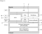
- a train control system based on connection between trains is broadly composed of wayside facilities and onboard equipment.
- the wayside facilities are composed of a control automatic train supervision (ATS) 1, a wayside data communication network, a precision stop marker (PSM) 2, and a trackside beacon 3 such as TAG/Balise.
- Onboard facilities are composed of an onboard wireless communication device 4, a PSM sensor 5, a beacon reader and antenna 6, the onboard equipment 7 such as onboard automatic train protection (ATP)/ onboard automatic train operation (ATO)/ onboard electronic interlocking system (EIS), etc., and a traction/braking system 8 of a train as a sub-system.
- a platform screen door (PSD) 9, a point machine (PM) 10, and an onboard ATP of the adjacent train transmit and receive control information therebetween through a wireless communication network.
- the onboard equipment 7 such as onboard ATP/ATO, etc. interfaces with the traction/braking system 8 of a train to control acceleration and deceleration of the train so as to secure a safe distance.
- the onboard equipment 7 calculates a track occupied section of a train and movement authority of a train by itself, and provides them to an adjacent train (following train).
- real-time information such as acceleration and deceleration control information, etc. including train characteristics.
- an object controller (OC) 20 performs wireless communication with the control ATS 1 and an onboard EIS 30.
- the OC 20 performs wired communication with the control ATS 1 and the onboard EIS 30 through the trackside wireless communication network base station 15.
- the OC 20 autonomously has wireless facilities, and thus the OC transmits and receives control information to and from the control ATS 1 and the onboard EIS 30 through wireless communication.
- the OC 20 is connected to the trackside wireless communication facilities through a cable, and thus control information is transmitted and received through wireless communication between the onboard EIS 30 and the trackside wireless communication base station 15.
- Such electronic interlocking system includes: the control ATS 1 performing a path command according to a unique schedule of a train; the onboard EIS 30 controlling the path of the train according to the command of the control ATS, and identifying integrity of the control; the PM 10 switching the track; and the OC 20 controlling the PM 10 according to a command of the onboard EIS 30, and providing state information of the PM 10 to the onboard EIS 30.
- the OC 20 is connected with at least one PM 10, and identifies state information of the PM such as a nominal or reverse state, a lock or unlock state, a fault or normal state, etc. of the PM, and provides the state information of the PM to the onboard EIS 30 or the control ATS 1.
- lock or unlock means that in order to control a particular PM 10 by the onboard EIS 30 through the OC 20, lock or unlock is performed on the resource (here, the PM) so as to prevent the particular PM 10 from being duplicately controlled by an onboard EIS 30 of another train.
- all PMs 10 at the trackside have a switching area 10a to which a fouling point is applied.
- the switching area is meaningful.
- the onboard EIS 30 of a train commands the OC 20 to lock and operate the PM 10.
- the onboard EIS 30 receives an operation state of the PM 10 from the OC 20 to identify the operation state, and provides the path as much as the switching area 10a of the secured PM 10 to the onboard ATP 32.
- FIG. 5 A process of transmitting and receiving information between components of each part of the train-centric electronic interlocking system is shown in FIG. 5 .
- the onboard EIS 30 receives a position, a travel direction of a train T, train route section occupancy information, and movement authority from the onboard ATP 32.
- the onboard EIS 30 receives a braking distance based on a current position and a current speed of the train in order to decide a lock condition.
- the onboard EIS 30 provides the end of the safe path to the onboard ATP 32.
- the onboard EIS 30 identifies a state of a PM 10 and commands control of the PM 10 through the OC 20.
- the OC 20 receives real-time state information of the PM 10 and provides the information to the onboard EIS 30.
- An onboard EIS 30 of every train T running on the route and wayside OCs 20 are respectively registered at single and multicast addresses.
- the onboard EIS 30 transmits and receives control information to and from the OC 20 through the communication addresses.
- the first method is receiving state information of the PM 10 from the OC 20 in response to a request of the onboard EIS 30, and the second method is periodically reporting supervised state information of the PM 10 by each OC 20, to the onboard EIS 30.
- FIG. 6 is a view for explaining request and response of the onboard EIS 30.
- the onboard EIS 30 receives the state information from a particular OC 20 connected with the particular PM 10 among all OCs.
- all trains running on the route receive the state information of the particular PM 10.
- an onboard EIS 30 that does not request the state information of the particular PM 10 among multiple onboard EISs 30 ignores the state information of the PM regardless of the reception.
- FIG. 7 shows a case where all PMs on the route periodically provide state information of themselves to all trains.
- an onboard EIS 30 of a particular train does not request state information of a particular PM 10.
- All OCs 20 periodically transmit supervised state information of the PMs 10 individually connected therewith, to onboard EIS 30s of all trains running on the route.
- the onboard EIS 30 stores IDs of all PMs 10 on the route and switching areas 10a of all PMs 10.
- an OC corresponding to a PM may be configured to provide a switching area of the PM.
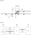
- the switching area 10a of the PM 10 is indicated as a distance from the trackside beacon 3 such as trackside TAG/Balise. That is, as shown in FIG. 8 , the switching area 10a may be indicated by using distances x and y from a random reference TAG. Therefore, the start point of the switching area may be indicated as a point spaced apart from TG_K that is an ID of the reference TAG by distance y, and the end point of the switching area may be indicated as a point spaced apart from TG_K by distance x.
- state information of a PM 10 managed by the onboard EIS 30 may be composed of as follows: a unique ID of the PM 10, a switching area, a nominal or reverse state, a lock or unlock state of the PM 10, a key value for accessing the PM, and an ID of the PM 10 in a case of twins.
- the values thereof may be set.
- Such state information of the PM 10 is composed as " ⁇ PM_ID, [TG_K + y, TG_K + x], Nominal/Reverse, Lock/Unlock, Key, Twin PM_ID>.”
- a method of locking an unlocked PM 10 by an onboard EIS 30 of a train through the OC 20 to secure the unlocked PM for its own resources is as follows.
- the onboard EIS 30 identifies whether a particular PM 10 is in an unlock state.
- the onboard EIS requests a change of the state of the particular PM 10 to a lock state, from an OC 20 connected to the particular PM 10. Accordingly, the OC 20 changes the state of the particular PM 10 to the lock state while generating a unique key value and providing the unique key value to the onboard EIS 30.
- the OC 20 receives state information from the PM 10 and identifies whether the PM is in a lock state, and generates a unique key value and provides the unique key value to the onboard EIS 30.
- the OC 20 when the PM 10 is in an unlock state and whenever the onboard EIS 30 has a lock request for the PM 10, the OC 20 always generates a new key value and provides the key value to the onboard EIS 30.
- the key value generated by the OC 20 should be long enough so as to prevent the onboard EIS 30 from being operated by an existing value and to prevent several OCs 20 from generating duplicate values.
- the onboard EIS 30 of a train postpones configuration of the path until all PMs that exist within the path received from the ATS 1 are secured. That is, only when all PMs are secured, a key value is obtained.
- the onboard EIS 30 transmits an unlock command to the OC 20 by using a key value received from the OC 20. Accordingly, the OC 20 enables the PM 10 to be unlock only by a command of an onboard EIS 30 that locked the PM 10.
- Such locking and unlocking of the PM 10 may be performed by manual handling of an operator of a control center besides the onboard EIS 30.
- the operator may identify the state of the PM 10 to be handled, through an operation monitor.
- a lock or unlock process is performed in the same manner as the case of the onboard EIS 30.
- track sections are separated into a switching area and a non-switching area that is not the switching area.
- Path information provided to the onboard ATP 32 by the onboard EIS 30 manages only the switching area of the PM 10. That is, as shown in FIG. 11 , in a case of all track sections except for the switching area 10a (non-switching area), the onboard EIS 30 provides a path to the onboard ATP 32 without any conditions.
- the path provided by the onboard EIS 30 to the onboard ATP 32 is configured based on a schedule command of the control ATS 1.
- a path to be provided includes a switching area 10a
- the onboard EIS 30 should identify a list of PMs 10 composing the path and a condition of each PM 10.
- the onboard EIS 30 receives the state by using the multicast address of the OC 20.
- the onboard EIS 30 of a train provided the path before a switching area corresponding to PM 21A and PM 21B, to the onboard ATP 32, and thus movement authority of the train may be extended to the X point as maximum.
- a train A receives the schedule command of the control ATS 1, and intends to enter a station in the direction of the red arrow.
- the control ATS 1 commands the onboard EIS 30 of the train A for a path related to the red arrow.
- the onboard EIS 30 of the train A requests state information of PM list ⁇ 21A, 21B, 23, 25> composing the path or receives a periodical report on the PM state from the OC 20.
- the onboard EIS 30 of the train A locks the PM list (the train A performs locking before performing unlocking so as to prevent the PM list from being occupied by another train), and next, a PM control command is transmitted to each OC 20 by using a control key value received from each PM and a multicast communication address.
- PM 21A and PM 21B are twin PMs, and thus when PM 21B is nominal, PM 21A is also nominal.
- the OC 20 of the PM 10 controls the PM 10 according to the command of the onboard EIS 30.
- the onboard EIS 30 of the train A receives state information of the PM from the OC 20 with respect to the control command, and identifies that the control of the PM is faultlessly performed.
- the onboard EIS 30 of the train A postpones the path of the train until all PMs in the requested list are in the unlock state. That is, the train A is unable to receive a path after the X point.
- the onboard EIS 30 identifies that the control of the PM 10 is faultlessly performed, and next, provides the path including switching areas of the PM list to the onboard ATP of the train.
- the onboard EIS 30 secured switching areas required to move from the X point to the Y point, namely, all switching areas of PM 21A & 21B, PM 23, and PM 25, whereby the end of the path that is safe to the Y point may be provided to the onboard ATP. Accordingly, the onboard ATP allows the onboard ATO (or the driver) to move the train to the Y point.
- the onboard EIS 30 when unlocking the path of the train, the onboard EIS 30 continuously receives the position of the train and an occupied section of the track from the onboard ATP 32. Therefore, whenever the rear end portion of the train moves out of the PM area while the train travels to the Y point, the onboard EIS 30 commands the OC 20 to unlock the PM 10 in order. Accordingly, the OC 20 that received the unlock command of the PM 10 unlocks the PM 10, and next, transmits the state information to the onboard EIS 30.
- detector locking means that when the train exists in the switching area of the track, namely, when the occupied section of the train exists in the switching area, the PM 10 is locked to be prevented from being arbitrarily switched. In a normal situation, the OC 20 does not allow another train to access, and thus when the train T exists in the switching area 10a of the PM 10, unlocking is not performed.
- the ID of the PM 10 and the unlock command for the PM 10 that the operator requires to unlock are transmitted to all onboard EISs 30 through the multicast communication address.
- the onboard EIS 30 occupying the PM 10 continuously receives the position of the train and the occupied section of the track from the onboard ATP 32.
- the onboard EIS 30 exists in the switching area 10a of the PM 10, and thus the onboard EIS 30 transmits unlock impossibility information to the control center or the OC 20 for the cognition of the operator. Otherwise, namely, when a train does not exist in the switching area of the PM and there is enough distance not to enter the switching area by a current train being stopping, a control key of the PM is returned to the OC 20 and the state of the PM is changed to the unlock state.
- the control ATS has a right to control the PM by obtaining the key returned to the OC 20.
- approach (stick) locking means that when the train T enters the switching area 10a, the PM handling the switching area 10a is locked to be prevented from being arbitrarily switched.
- the onboard EIS 30, from the ATP 32 may receive real-time position and occupancy information of the train, a current braking distance, and movement authority.
- movement authority of the ATP 32 and a limit speed may be set to stop the train T in front of an unauthorized PM 10 without fail.
- the onboard EIS 30 of the train having the key identifies whether the current braking distance of the train reaches the switching area 10a (namely, whether derailment may occur when the train brakes now), whereby whether the command is applied is decided.
- FIG. 13 is a view showing a case where it is impossible for the operator to force to implement unlocking when determining whether approach (stick) locking is performed.
- FIG. 14 is a view showing a case where it is possible for the operator to force to implement unlocking when determining whether approach (stick) locking is performed.
- the onboard EIS 30 accepts the request of the operator, and unlocks the PM 10.
- movement authority of the train is shortened as shown in FIG. 15 , and the train T stops outside of the switching area 10a.
- the path of the train T means a list of PMs in series.
- Path locking means that start and end PMs composing the path of the train should not be unlocked until the train requests unlock while passing.
- a general track section may exist between the PMs of the list.
- the present invention relates to a train-centric electronic interlocking system and method for an autonomous train control system based on connection between trains.
Landscapes
- Engineering & Computer Science (AREA)
- Mechanical Engineering (AREA)
- Automation & Control Theory (AREA)
- Transportation (AREA)
- Electric Propulsion And Braking For Vehicles (AREA)
- Train Traffic Observation, Control, And Security (AREA)
Description
- The present invention relates to a train-centric electronic interlocking system and method for an autonomous train control system based on connection between trains.
- Generally, a railroad vehicle is large-scale transportation machine that transports large amounts of freight or many passengers, and a railroad vehicle is equipped with various types of train control systems having various degrees of complexity so that the vehicle can be safely driven along a track.
- Here, train control systems utilize complicated system configurations where various types of supervisions and controls are possible to take charge of safe operation of the train. For safe operation of two trains, it is extremely important to secure a safe distance between preceding and following trains and a safe speed, and an example thereof is proposed in
Korean Patent No. 10-1449742 - Therefore, a device for measuring a position and a speed of a preceding train in real time is provided in a train, and an onboard system is configured to calculate a safe distance between trains by using movement authority received from a wayside system and speed and position values of the preceding train measured in the train, whereby it is proposed that train distance control between the preceding train and the following train is automatically performed in a range where the proximate driving is possible without human intervention.
- Among such conventional wireless communications-based train control systems, a wayside-centric wireless communications-based train control system such as a communications-based train control (CBTC) system performs wayside-centric distance control based on control information between an onboard system and a wayside system.
-
Document EP 1 695 890 A1 describes a signalling system for ensuring the protection of a train, comprising an interlocking device. - However, all trains of the control area at the wayside are controlled depending on centralized control systems such as a wayside automatic train protection (ATP), a wayside electronic interlocking system (EIS), etc., and thus when more than the predetermined number of trains are deployed, there is a limit to the processing capacity. Therefore, it is required to establish more facilities depending on a predetermined section or the processing capacity. For example, document
EP-A-1695890 discloses signaling system, train with control apparatus and point protection apparatus. - In order to solve such problems, it is required that a new autonomous train control system based on communication connection between trains performs safe train operation through control information interchange between trains without wayside facilities such as wayside ATP, EIS, etc.
- Accordingly, the present invention has been made keeping in mind the above problems occurring in the related art, and an object of the present invention is to provide a train-centric electronic interlocking system and method for an autonomous train control system based on connection between trains, the train-centric electronic interlocking system and method reducing system installation and maintenance costs by reducing wayside EIS facilities.
- Particularly, an object of the present invention is to provide a train-centric electronic interlocking system and method for an autonomous train control system based on connection between trains, the train-centric electronic interlocking system and method simplifying a control path by enhancing flexibility and scalability of the system based on an onboard EIS.
- In order to accomplish the above object, the present invention provides:
a train-centric electronic interlocking system for an autonomous train control system based on connection between trains, the train-centric electronic interlocking system including: a control automatic train supervision (ATS) configured to perform a path command according to a unique schedule of a train; an onboard electronic interlocking system (EIS) configured to control a path of the train according to the command of the control ATS, and identifying integrity of the control; a point machine (PM) configured to switch a track of a switching area; and an object controller (OC) configured to control the PM according to a command of the onboard EIS, and providing state information of the PM to the onboard EIS. The state information of the point machine managed by the onboard electronic interlocking system includes a unique ID of the point machine, the switching area, a nominal or reverse state, a lock or unlock state of the point machine, and a key value for accessing the point machine. The object controller is configured to change the state of the point machine to the lock state while generating a unique key value and providing the unique key value to the onboard electronic interlocking system. - Here, the OC may identify the state information of the PM and may provide the state information to the onboard EIS, the state information including a nominal or reverse state, a lock or unlock state, a fault or normal state of the PM.
- In addition, the PM may have the switching area to which a fouling point is applied, and the onboard EIS may receive an operation state of the PM from the OC to identify the operation state, and may provide the path as much as the switching area of the secured PM to an onboard automatic train protection (ATP).
- In addition, the present invention provides:
a train-centric electronic interlocking method for an autonomous train control system based on connection between trains, the train-centric electronic interlocking method including: receiving, by an onboard electronic interlocking system (EIS) of a train atstep 1, state information of a point machine (PM) list of multiple PMs composing a path based on a path command of a control automatic train supervision (ATS) from an object controller (OC) of a PM to identify the state information of the point machines of said list; identifying, by the onboard EIS atstep 2, whether a particular PM in said list is in an unlock or lock state, and requesting a change of the state of the particular PM to the lock state, from the OC connected to the particular PM when determining the particular PM is in the unlock state; receiving, by the onboard EIS atstep 3, a unique key value required for accessing the particular PM from the OC, the unique key value being generated while changing the state of the particular PM to the lock state; and transmitting, by the onboard EIS atstep 4, an unlock command to the OC connected with the particular PM by using the key value received from the OC, whereby the particular PM is unlocked. - Here, the
step 1 may include: transmitting, by the onboard EIS of the train at step 1_1, a state request message requesting the state information of the particular PM to all OCs of a route; and receiving, by the onboard EIS at step 1_2, the state information of the particular PM from the OC of the particular PM. - In addition, at the
step 1, the onboard EIS of the train may receive supervised state information of the PMs from all OCs that are individually connected with the PMs. - Furthermore, before the
step 1, the method may include receiving, by the onboard EIS atstep 5, the path command from the control ATS according to a unique schedule of the train, and storing IDs of all PMs of a route and switching areas of the PMs. - Also, the state information of the PM managed by the onboard EIS may include a unique ID of the PM, a switching area, a nominal or reverse state, a lock or unlock state of the PM, and a key value for accessing the PM.
- Furthermore, at the
step 2, the path of the train may be postponed until all PMs in the PM list requested by the onboard EIS are in the unlock state. - In addition, the
step 4 may include: continuously receiving, by the onboard EIS at step 4_1, the position of the train and an occupied section of the track from an onboard automatic train protection (ATP), and when a rear end portion of the train moves out of a PM area, commanding the OC of the PM to unlock the PM; and receiving, by the onboard EIS at step 4_2, state information after changing the state of the PM to the unlock state, from the OC that received the unlock command for the PM. - Furthermore, at the
step 4, when the onboard EIS receives the forced unlock command for the locked PM from the OC of the PM in the lock state or from a control center while the train exists in a switching area, the onboard EIS may transmit unlock impossibility information to the control center or the OC. - In addition, at the
step 4, when a current braking distance of the train received from an automatic train protection (ATP) exists in a non-switching area of the particular PM, the forced unlock command for the particular PM may be transmitted from a control center to the OC connected with the particular PM and to the onboard EIS; and the onboard EIS having the key of the particular PM may identify whether the particular PM can be unlocked, and may return the key to the OC of the particular PM, whereby the particular PM is unlocked. - As described above, according to the present invention, a system for the autonomous train control system based on connection between trains is simplified based on the onboard EIS without requiring wayside EIS facilities, whereby installation and maintenance costs of the system can be reduced.
- In addition, according to the present invention, it is possible to enhance flexibility and scalability of a system based on the onboard EIS. That is, the present invention can provide onboard facilities that were used as wayside facilities in a conventional wayside-centric wireless communications-based train driving safety system, whereby a control path can be simplified and can flexibly reply to operational change.
-
-
FIG. 1 is a block diagram showing an autonomous train control system based on connection between trains for the present invention. -
FIG. 2 is a configuration diagram showing a train-centric electronic interlocking system for an autonomous train control system based on connection between trains according for an embodiment of the present invention. -
FIG. 3 is a configuration diagram showing a train-centric electronic interlocking system for an autonomous train control system based on connection between trains for another embodiment of the present invention. -
FIG. 4 is a view showing an example of a switching area of an object controller (OC) and a point machine (PM) for the present invention. -
FIG. 5 is a view for explaining a process of transmitting and receiving information between components of a train-centric electronic interlocking system for to the present invention. -
FIGS. 6a and6b are views for explaining processes of requesting and responding to state information of a PM by an onboard electronic interlocking system (EIS) for the present invention. -
FIG. 7 is a view for explaining a process of periodically reporting state information of a PM to an onboard EIS for the present invention. -
FIG. 8 is a view for explaining a switching area of a PM for the present invention. -
FIG. 9 is a view for explaining a lock process of a PM through an OC for the present invention. -
FIG. 10 is a view for explaining an unlock process of a PM through an OC of the present invention. -
FIG. 11 is a view for explaining an example of separation of a track section managed by an onboard EIS for the present invention. -
FIG. 12 is a view for explaining an example of train path configurations for the present invention. -
FIGS. 13 and 14 are views for explaining a process of determining whether approach (stick) locking is performed by an onboard EIS for the present invention. -
FIG. 15 is a view for explaining a situation where movement authority (MA) is shortened by reducing a path due to forced unlock by an operator for the present invention. - Hereinafter, features of a train-centric electronic interlocking system and method for an autonomous train control system based on connection between trains according to the present invention will be understood through a detailed description of the embodiment of the present invention with reference to the accompanying drawings.
- First, referring to
FIG. 1 , a train control system based on connection between trains is broadly composed of wayside facilities and onboard equipment. - Here, the wayside facilities are composed of a control automatic train supervision (ATS) 1, a wayside data communication network, a precision stop marker (PSM) 2, and a
trackside beacon 3 such as TAG/Balise. Onboard facilities are composed of an onboardwireless communication device 4, aPSM sensor 5, a beacon reader andantenna 6, theonboard equipment 7 such as onboard automatic train protection (ATP)/ onboard automatic train operation (ATO)/ onboard electronic interlocking system (EIS), etc., and a traction/braking system 8 of a train as a sub-system. - In the meantime, there are no wayside control facilities in the present invention, and thus a platform screen door (PSD) 9, a point machine (PM) 10, and an onboard ATP of the adjacent train transmit and receive control information therebetween through a wireless communication network. The
onboard equipment 7 such as onboard ATP/ATO, etc. interfaces with the traction/braking system 8 of a train to control acceleration and deceleration of the train so as to secure a safe distance. - In such a train control system based on connection between trains, the
onboard equipment 7 calculates a track occupied section of a train and movement authority of a train by itself, and provides them to an adjacent train (following train). In addition, it is possible to provide real-time information such as acceleration and deceleration control information, etc. including train characteristics. - Hereinafter, configurations of the train-centric electronic interlocking system for the autonomous train control system based on connection between trains according to the present invention will be described.
- Here, in the electronic interlocking system of the train control system based on connection between trains, as shown in
FIG. 2 , an object controller (OC) 20 performs wireless communication with thecontrol ATS 1 and anonboard EIS 30. Alternatively, as shown inFIG. 3 , when it is easy to connect the point machine (PM) (track switch) 10 to a trackside wireless communicationnetwork base station 15, theOC 20 performs wired communication with thecontrol ATS 1 and theonboard EIS 30 through the trackside wireless communicationnetwork base station 15. - More specifically, in a case of
FIG. 2 , theOC 20 autonomously has wireless facilities, and thus the OC transmits and receives control information to and from thecontrol ATS 1 and theonboard EIS 30 through wireless communication. In contrast, in a case ofFIG. 3 , theOC 20 is connected to the trackside wireless communication facilities through a cable, and thus control information is transmitted and received through wireless communication between theonboard EIS 30 and the trackside wirelesscommunication base station 15. - Such electronic interlocking system includes: the
control ATS 1 performing a path command according to a unique schedule of a train; theonboard EIS 30 controlling the path of the train according to the command of the control ATS, and identifying integrity of the control; thePM 10 switching the track; and theOC 20 controlling thePM 10 according to a command of theonboard EIS 30, and providing state information of thePM 10 to theonboard EIS 30. - Here, the
OC 20 is connected with at least onePM 10, and identifies state information of the PM such as a nominal or reverse state, a lock or unlock state, a fault or normal state, etc. of the PM, and provides the state information of the PM to theonboard EIS 30 or thecontrol ATS 1. - In the concept of Mutex, lock or unlock means that in order to control a
particular PM 10 by theonboard EIS 30 through theOC 20, lock or unlock is performed on the resource (here, the PM) so as to prevent theparticular PM 10 from being duplicately controlled by anonboard EIS 30 of another train. - Here, as shown in
FIG. 4 , allPMs 10 at the trackside have aswitching area 10a to which a fouling point is applied. Here, for example, in a case of twin PMs such asPM 21A andPM 21B, and a reverse state, the switching area is meaningful. Through this, theonboard EIS 30 of a train commands theOC 20 to lock and operate thePM 10. In addition, theonboard EIS 30 receives an operation state of thePM 10 from theOC 20 to identify the operation state, and provides the path as much as theswitching area 10a of thesecured PM 10 to theonboard ATP 32. - A process of transmitting and receiving information between components of each part of the train-centric electronic interlocking system is shown in
FIG. 5 . According to this, theonboard EIS 30 receives a position, a travel direction of a train T, train route section occupancy information, and movement authority from theonboard ATP 32. In addition, theonboard EIS 30 receives a braking distance based on a current position and a current speed of the train in order to decide a lock condition. In addition, theonboard EIS 30 provides the end of the safe path to theonboard ATP 32. Also, theonboard EIS 30 identifies a state of aPM 10 and commands control of thePM 10 through theOC 20. Furthermore, theOC 20 receives real-time state information of thePM 10 and provides the information to theonboard EIS 30. - Hereinafter, an operation process of the train-centric electronic interlocking system for the autonomous train control system based on connection between trains according to the present invention will be described with reference to
FIGS. 6 to 15 . - First, a communication method between the
onboard EIS 30 and theOC 20 will be described with reference toFIGS. 6 and7 . - An
onboard EIS 30 of every train T running on the route andwayside OCs 20 are respectively registered at single and multicast addresses. Theonboard EIS 30 transmits and receives control information to and from theOC 20 through the communication addresses. - Here, there are two methods of identifying the state of the
PM 10 by theonboard EIS 30 as shown inFIGS. 6 to 7 . The first method is receiving state information of thePM 10 from theOC 20 in response to a request of theonboard EIS 30, and the second method is periodically reporting supervised state information of thePM 10 by eachOC 20, to theonboard EIS 30. - First,
FIG. 6 is a view for explaining request and response of theonboard EIS 30. - According to this, assuming that K trains T and
N PMs 10 exist on the route, for example, as shown inFIG. 6a , when anonboard EIS 30 oftrain # 1, which is a particular train, requests state information of aparticular PM 10, a state request message is transmitted to allOCs 20. - In the meantime, as shown in
FIG. 6b , in response to the state request message, theonboard EIS 30 receives the state information from aparticular OC 20 connected with theparticular PM 10 among all OCs. Here, all trains running on the route receive the state information of theparticular PM 10. However, anonboard EIS 30 that does not request the state information of theparticular PM 10 among multipleonboard EISs 30 ignores the state information of the PM regardless of the reception. - That is, when an
onboard EIS 30 of a particular train requests state information of aparticular PM 10, a state request message is transmitted to allOCs 20, and the state information is received from aparticular OC 20 connected to theparticular PM 10 among all OCs. - In addition,
FIG. 7 shows a case where all PMs on the route periodically provide state information of themselves to all trains. According to this, assuming that K trains T andN PMs 10 exist on the route, anonboard EIS 30 of a particular train does not request state information of aparticular PM 10. AllOCs 20 periodically transmit supervised state information of thePMs 10 individually connected therewith, to onboard EIS 30s of all trains running on the route. - Hereinafter, a process of storing state information of a PM by an onboard EIS will be described with reference to
FIG. 8 . - The
onboard EIS 30 stores IDs of allPMs 10 on the route and switchingareas 10a of allPMs 10. Alternatively, an OC corresponding to a PM may be configured to provide a switching area of the PM. - Here, the switching
area 10a of thePM 10 is indicated as a distance from thetrackside beacon 3 such as trackside TAG/Balise. That is, as shown inFIG. 8 , the switchingarea 10a may be indicated by using distances x and y from a random reference TAG. Therefore, the start point of the switching area may be indicated as a point spaced apart from TG_K that is an ID of the reference TAG by distance y, and the end point of the switching area may be indicated as a point spaced apart from TG_K by distance x. - In the meantime, state information of a
PM 10 managed by theonboard EIS 30 may be composed of as follows: a unique ID of thePM 10, a switching area, a nominal or reverse state, a lock or unlock state of thePM 10, a key value for accessing the PM, and an ID of thePM 10 in a case of twins. - Here, in the state information of the
PM 10 managed by theonboard EIS 30, only when the nominal or reverse state and the lock or unlock state of thePM 10 are received through theOC 20, the values thereof may be set. - Such state information of the
PM 10 is composed as "<PM_ID, [TG_K + y, TG_K + x], Nominal/Reverse, Lock/Unlock, Key, Twin PM_ID>." - Next, lock and unlock processes of a single PM will be described with reference to
FIGS. 9 and10 . - First, a method of locking an
unlocked PM 10 by anonboard EIS 30 of a train through theOC 20 to secure the unlocked PM for its own resources is as follows. - Referring to
FIG. 9 , theonboard EIS 30 identifies whether aparticular PM 10 is in an unlock state. When theparticular PM 10 is identified as in the unlock state, the onboard EIS requests a change of the state of theparticular PM 10 to a lock state, from anOC 20 connected to theparticular PM 10. Accordingly, theOC 20 changes the state of theparticular PM 10 to the lock state while generating a unique key value and providing the unique key value to theonboard EIS 30. - The
OC 20 receives state information from thePM 10 and identifies whether the PM is in a lock state, and generates a unique key value and provides the unique key value to theonboard EIS 30. - Here, when the
PM 10 is in an unlock state and whenever theonboard EIS 30 has a lock request for thePM 10, theOC 20 always generates a new key value and provides the key value to theonboard EIS 30. - In addition, the key value generated by the
OC 20 should be long enough so as to prevent theonboard EIS 30 from being operated by an existing value and to preventseveral OCs 20 from generating duplicate values. - When several PMs exist within the path rather than a single PM, the
onboard EIS 30 of a train postpones configuration of the path until all PMs that exist within the path received from theATS 1 are secured. That is, only when all PMs are secured, a key value is obtained. - In the meantime, referring to
FIG. 10 , in order to unlock thePM 10 secured by theonboard EIS 30, theonboard EIS 30 transmits an unlock command to theOC 20 by using a key value received from theOC 20. Accordingly, theOC 20 enables thePM 10 to be unlock only by a command of anonboard EIS 30 that locked thePM 10. - In the locking of the PM, the path is postponed until all PMs received from an ATS path command are secured. In contrast, in the unlock state, whenever a train moves out of a PM area, each PM is unlocked in order.
- Such locking and unlocking of the
PM 10 may be performed by manual handling of an operator of a control center besides theonboard EIS 30. The operator may identify the state of thePM 10 to be handled, through an operation monitor. When thePM 10 is in the unlock state by another train, a lock or unlock process is performed in the same manner as the case of theonboard EIS 30. - In addition, separation of a track section will be described with reference to
FIG. 11 . - In the train-centric electronic interlocking system according to the present invention, track sections are separated into a switching area and a non-switching area that is not the switching area. Path information provided to the
onboard ATP 32 by theonboard EIS 30 manages only the switching area of thePM 10. That is, as shown inFIG. 11 , in a case of all track sections except for theswitching area 10a (non-switching area), theonboard EIS 30 provides a path to theonboard ATP 32 without any conditions. - Next, train path configurations and provisions, and unlocking will be described with reference to
FIG. 12 . - The path provided by the
onboard EIS 30 to theonboard ATP 32 is configured based on a schedule command of thecontrol ATS 1. Here, when a path to be provided includes aswitching area 10a, theonboard EIS 30 should identify a list ofPMs 10 composing the path and a condition of eachPM 10. - Here, in order to secure the PM list, the
onboard EIS 30 receives the state by using the multicast address of theOC 20. InFIG. 12 , theonboard EIS 30 of a train provided the path before a switching area corresponding toPM 21A andPM 21B, to theonboard ATP 32, and thus movement authority of the train may be extended to the X point as maximum. - For example, a train A receives the schedule command of the
control ATS 1, and intends to enter a station in the direction of the red arrow. Thecontrol ATS 1 commands theonboard EIS 30 of the train A for a path related to the red arrow. Based on the path command of thecontrol ATS 1, theonboard EIS 30 of the train A requests state information of PM list <21A, 21B, 23, 25> composing the path or receives a periodical report on the PM state from theOC 20. - Here, for example, when all
PMs 10 in the PM list namely, all states of <21A, 21B, 23, 25> are the unlock state (resource not occupied by another train), theonboard EIS 30 of the train A locks the PM list (the train A performs locking before performing unlocking so as to prevent the PM list from being occupied by another train), and next, a PM control command is transmitted to eachOC 20 by using a control key value received from each PM and a multicast communication address. - That is, <21A-nominal, 21B-nominal, 23-reverse, 25-nominal> command is transmitted.
PM 21A andPM 21B are twin PMs, and thus whenPM 21B is nominal,PM 21A is also nominal. TheOC 20 of thePM 10 controls thePM 10 according to the command of theonboard EIS 30. Theonboard EIS 30 of the train A receives state information of the PM from theOC 20 with respect to the control command, and identifies that the control of the PM is faultlessly performed. - Here, when any PM in the requested PM list is not in the unlock state, the
onboard EIS 30 of the train A postpones the path of the train until all PMs in the requested list are in the unlock state. That is, the train A is unable to receive a path after the X point. - In the meantime, when providing the path of the train, the
onboard EIS 30 identifies that the control of thePM 10 is faultlessly performed, and next, provides the path including switching areas of the PM list to the onboard ATP of the train. InFIG. 12 , when the end of the path to be provided to the train A is the Y point, theonboard EIS 30 secured switching areas required to move from the X point to the Y point, namely, all switching areas ofPM 21A & 21B,PM 23, and PM 25, whereby the end of the path that is safe to the Y point may be provided to the onboard ATP. Accordingly, the onboard ATP allows the onboard ATO (or the driver) to move the train to the Y point. - In addition, when unlocking the path of the train, the
onboard EIS 30 continuously receives the position of the train and an occupied section of the track from theonboard ATP 32. Therefore, whenever the rear end portion of the train moves out of the PM area while the train travels to the Y point, theonboard EIS 30 commands theOC 20 to unlock thePM 10 in order. Accordingly, theOC 20 that received the unlock command of thePM 10 unlocks thePM 10, and next, transmits the state information to theonboard EIS 30. - Hereinafter, a process of performing lock logic will be described with reference to
FIGS. 13 to 15 . - First, detector locking means that when the train exists in the switching area of the track, namely, when the occupied section of the train exists in the switching area, the
PM 10 is locked to be prevented from being arbitrarily switched. In a normal situation, theOC 20 does not allow another train to access, and thus when the train T exists in theswitching area 10a of thePM 10, unlocking is not performed. - When the operator uses the
OC 20 to unlock aPM 10 that is already locked by anonboard EIS 30 of a particular train T, the information of the command is transmitted to allOCs 20 on the route andonboard EISs 30 of all trains. - That is, the ID of the
PM 10 and the unlock command for thePM 10 that the operator requires to unlock are transmitted to allonboard EISs 30 through the multicast communication address. Theonboard EIS 30 occupying thePM 10 continuously receives the position of the train and the occupied section of the track from theonboard ATP 32. Theonboard EIS 30 exists in theswitching area 10a of thePM 10, and thus theonboard EIS 30 transmits unlock impossibility information to the control center or theOC 20 for the cognition of the operator. Otherwise, namely, when a train does not exist in the switching area of the PM and there is enough distance not to enter the switching area by a current train being stopping, a control key of the PM is returned to theOC 20 and the state of the PM is changed to the unlock state. Next, the control ATS has a right to control the PM by obtaining the key returned to theOC 20. - Next, approach (stick) locking means that when the train T enters the
switching area 10a, the PM handling theswitching area 10a is locked to be prevented from being arbitrarily switched. In the train-centric electronic interlocking system, theonboard EIS 30, from theATP 32, may receive real-time position and occupancy information of the train, a current braking distance, and movement authority. In addition, movement authority of theATP 32 and a limit speed may be set to stop the train T in front of anunauthorized PM 10 without fail. - When the operator forces to implement unlocking while the train T normally approaches to the switching area, information is transmitted to all
OCs 20 on the route and theonboard EIS 30 of the train. Based on the ID of thePM 10, theonboard EIS 30 of the train having the key identifies whether the current braking distance of the train reaches theswitching area 10a (namely, whether derailment may occur when the train brakes now), whereby whether the command is applied is decided. -
FIG. 13 is a view showing a case where it is impossible for the operator to force to implement unlocking when determining whether approach (stick) locking is performed. When the train approaches the switching area and the operator intends to unlock thePM 10 through theOC 20, the request of the operator is transmitted to theonboard EIS 30 occupying thePM 10. However, the current braking distance of the train T reaches theswitching area 10a, and thus theonboard EIS 30 may refuse the command of the operator. -
FIG. 14 is a view showing a case where it is possible for the operator to force to implement unlocking when determining whether approach (stick) locking is performed. When the current braking distance of the train received from theATP 32 exists outside of theswitching area 10a, theonboard EIS 30 accepts the request of the operator, and unlocks thePM 10. In response to the unlock, movement authority of the train is shortened as shown inFIG. 15 , and the train T stops outside of theswitching area 10a. - Next, in the train-centric electronic interlocking system, the path of the train T means a list of PMs in series. Path locking means that start and end PMs composing the path of the train should not be unlocked until the train requests unlock while passing. As shown in
FIG. 11 , rather than the switching section, a general track section (non-switching area) may exist between the PMs of the list. - When the operator forces the
particular PM 10 to be unlocked after the path for the train T is configured, the request of the operator is transmitted to theonboard EIS 30 occupying the resource of theparticular PM 10. An unlock request is decided in the same manner as the case of the approach (stick) locking. - Although exemplary embodiments of the present invention have been described for illustrative purposes, the invention is defined by the features of the independent claims.
- The present invention relates to a train-centric electronic interlocking system and method for an autonomous train control system based on connection between trains.
Claims (12)
- A train-centric electronic interlocking method for an autonomous train control system based on connection between trains, the train-centric electronic interlocking method comprising:receiving, by an onboard electronic interlocking system (30) of a train at step 1, state information of a point machine (10) list of multiple point machines (10) composing a path based on a path command of a control automatic train supervision (1) from an object controller (20) of a point machine (10) to identify the state information of the point machines (10) of said list;identifying, by the onboard electronic interlocking system (30) at step 2, whether a particular point machine (10) in said list is in an unlock or lock state, and requesting a change of the state of the particular point machine (10) to the lock state, from the object controller (20) connected to the particular point machine (10) when determining the particular point machine (10) is in the unlock state;characterised byreceiving, by the onboard electronic interlocking system (30) at step 3, a unique key value required for accessing the particular point machine (10) from the object controller (20), the unique key value being generated while changing the state of the particular point machine (10) to the lock state; andtransmitting, by the onboard electronic interlocking system (30) at step 4, an unlock command to the object controller (20) connected with the particular point machine (10) by using the key value received from the object controller (20), whereby the particular point machine (10) is unlocked.
- The train-centric electronic interlocking method of claim 1, wherein the step 1 comprises:transmitting, by the onboard electronic interlocking system (30) of the train at step 1_1, a state request message requesting the state information of the particular point machine (10) to all object controllers (20) of a route; andreceiving, by the onboard electronic interlocking system (30) at step 1_2, the state information of the particular point machine (10) from the object controller (20) of the particular point machine (10).
- The train-centric electronic interlocking method of claim 1, wherein at the step 1, the onboard electronic interlocking system (30) of the train receives supervised state information of the point machines (10) from all object controllers (20) that are individually connected with the point machines (10).
- The train-centric electronic interlocking method of claim 1, further comprising, before the step 1:
receiving, by the onboard electronic interlocking system (30) at step 5, the path command from the control automatic train supervision (1) according to a unique schedule of the train, and storing IDs of all point machines (10) of a route and switching areas of the point machines (10). - The train-centric electronic interlocking method of claim 1, wherein the state information of the point machine (10) managed by the onboard electronic interlocking system (30) includes a unique ID of the point machine (10), a switching area, a nominal or reverse state, a lock or unlock state of the point machine (10), and a key value for accessing the point machine (10).
- The train-centric electronic interlocking method of claim 1, wherein at the step 2, the path of the train is postponed until all point machines (10) in the point machine (10) list requested by the onboard electronic interlocking system (30) are in the unlock state.
- The train-centric electronic interlocking method of claim 1, wherein the step 4 comprises:continuously receiving, by the onboard electronic interlocking system (30) at step 4_1, the position of the train and an occupied section of the track from an onboard automatic train protection (32), and when a rear end portion of the train moves out of a point machine (10) area, commanding the object controller (20) of the point machine (10) to unlock the point machine (10); andreceiving, by the onboard electronic interlocking system (30) at step 4_2, state information after changing the state of the point machine (10) to the unlock state, from the object controller (20) that received the unlock command for the point machine (10).
- The train-centric electronic interlocking method of claim 1, wherein at the step 4, when the onboard electronic interlocking system (30) receives the forced unlock command for the locked point machine (10) from the object controller (20) of the point machine (10) in the lock state or from a control center while the train exists in a switching area, the onboard electronic interlocking system (30) transmits unlock impossibility information to the control center or the object controller (20).
- The train-centric electronic interlocking method of claim 1, wherein at the step 4,when a current braking distance of the train received from an automatic train protection (32) exists in a non-switching area of the particular point machine (10), the onboard electronic interlocking system (30) transmits the forced unlock command for the particular point machine (10) from a control center to the object controller (20) connected with the particular point machine (10) and to the onboard electronic interlocking system (30); andthe onboard electronic interlocking system (30) having the key of the particular point machine (10) identifies whether the particular point machine (10) can be unlocked, and returns the key to the object controller (20) of the particular point machine (10), whereby the particular point machine (10) is unlocked.
- A train-centric electronic interlocking system for an autonomous train control system based on connection between trains, the train-centric electronic interlocking system being suitable for carrying out a train-centric electronic interlocking method according to any preceding claims and comprising:a control automatic train supervision (1) configured to perform a path command according to a unique schedule of a train;an onboard electronic interlocking system (30) configured to control a path of the train according to the command of the control automatic train supervision (1), and identifying integrity of the control;a point machine (10) configured to switch a track of a switching area; andan object controller (20) configured to control the point machine (10) according to a command of the onboard electronic interlocking system (30), and providing state information of the point machine (10) to the onboard electronic interlocking system (30),wherein the state information of the point machine (10) managed by the onboard electronic interlocking system (30) includes a unique ID of the point machine (10), the switching area, a nominal or reverse state, a lock or unlock state of the point machine (10), and a key value for accessing the point machine (10), andwherein the object controller (20) is configured to change the state of the point machine (10) to the lock state while generating a unique key value and providing the unique key value to the onboard electronic interlocking system (30) .
- The train-centric electronic interlocking system of claim 10, wherein the object controller (20) is configured to identify the state information of the point machine (10) and to provide the state information to the onboard electronic interlocking system (30), the state information including a nominal or reverse state, a lock or unlock state, a fault or normal state of the point machine (10).
- The train-centric electronic interlocking system of claim 10, wherein the point machine (10) has the switching area to which a fouling point is applied, andthe onboard electronic interlocking system (30) is configured to receive an operation state of the point machine (10) from the object controller (20) to identify the operation state, and to providethe path as much as the switching area of the secured point machine (10) to an onboard automatic train protection (32).
Applications Claiming Priority (2)
| Application Number | Priority Date | Filing Date | Title |
|---|---|---|---|
| KR1020160096257A KR101834854B1 (en) | 2016-07-28 | 2016-07-28 | train-centric electronic interlocking system for connected train based autonomous train control system and the method thereof |
| PCT/KR2016/008548 WO2018021606A1 (en) | 2016-07-28 | 2016-08-03 | Onboard-based electronic interlocking system and method therefor for inter-train connection-based autonomous train control system |
Publications (4)
| Publication Number | Publication Date |
|---|---|
| EP3299250A1 EP3299250A1 (en) | 2018-03-28 |
| EP3299250A4 EP3299250A4 (en) | 2018-09-05 |
| EP3299250B1 true EP3299250B1 (en) | 2024-10-16 |
| EP3299250C0 EP3299250C0 (en) | 2024-10-16 |
Family
ID=61016368
Family Applications (1)
| Application Number | Title | Priority Date | Filing Date |
|---|---|---|---|
| EP16869387.7A Active EP3299250B1 (en) | 2016-07-28 | 2016-08-03 | Onboard-based electronic interlocking system and method therefor for inter-train connection-based autonomous train control system |
Country Status (4)
| Country | Link |
|---|---|
| EP (1) | EP3299250B1 (en) |
| KR (1) | KR101834854B1 (en) |
| CN (1) | CN108430852B (en) |
| WO (1) | WO2018021606A1 (en) |
Families Citing this family (18)
| Publication number | Priority date | Publication date | Assignee | Title |
|---|---|---|---|---|
| KR102206128B1 (en) * | 2018-11-16 | 2021-01-25 | 한국철도기술연구원 | Exclusive Track Resource Sharing System |
| KR102067564B1 (en) * | 2019-06-05 | 2020-02-11 | 대아티아이 (주) | System of Speed by Design of Movement Authority and the method using it |
| KR102316767B1 (en) * | 2019-11-11 | 2021-10-27 | 한국철도기술연구원 | Automatic Train Stop System |
| KR102354585B1 (en) | 2019-12-18 | 2022-01-26 | 한국철도기술연구원 | Handover Time Determination Method of Train Autonomous Driving Terminal |
| CN111497905B (en) * | 2020-04-27 | 2022-06-24 | 卡斯柯信号有限公司 | Rail transit signal system based on software definition and implementation method thereof |
| CN111923967B (en) * | 2020-10-10 | 2021-01-22 | 北京和利时系统工程有限公司 | Enhanced CBTC train control system |
| KR102578983B1 (en) | 2020-10-30 | 2023-09-19 | 한국철도기술연구원 | Security system of autonomous train system supporting ALM |
| KR102481098B1 (en) | 2020-11-06 | 2022-12-28 | 한국철도기술연구원 | Object controller and its interlocking control method for autonomous driving control system |
| CN113264086B (en) * | 2021-06-08 | 2022-08-26 | 卡斯柯信号有限公司 | Train interval protection control method and device based on TACS (train operating System) |
| CN113415315B (en) * | 2021-07-06 | 2023-10-17 | 北京全路通信信号研究设计院集团有限公司 | Method and system for switching control rights of general vehicle-mounted equipment and special vehicle-mounted equipment |
| CN114296422B (en) * | 2021-11-23 | 2024-03-29 | 卡斯柯信号有限公司 | CTC 3.0-based station yard centralized display and control method, equipment and medium |
| CN114475727B (en) * | 2022-03-15 | 2023-09-26 | 北京全路通信信号研究设计院集团有限公司 | Manual unlocking method and system for short route |
| CN115366955B (en) * | 2022-08-18 | 2023-11-28 | 北京和利时系统工程有限公司 | Method, apparatus and storage medium for establishing derailment protection zone |
| CN115649247B (en) * | 2022-10-10 | 2024-09-10 | 交控科技股份有限公司 | Rail transit signal simulation test system, method, electronic equipment and storage medium |
| KR102860870B1 (en) * | 2022-10-31 | 2025-09-18 | 한국철도기술연구원 | Integrated control device having automatic train protection and electronic interlocking functions and method for integrally controlling using the same |
| CN116176663B (en) * | 2022-12-08 | 2024-10-18 | 卡斯柯信号有限公司 | Method, equipment and medium for preventing unexpected movement of fully automatic coupled operation train |
| CN117227805B (en) * | 2023-09-11 | 2026-02-27 | 成都交控轨道科技有限公司 | A method for switching field control authority between the central control center and the vehicle base |
| GB2635352A (en) * | 2023-11-08 | 2025-05-14 | Universal Signalling Ltd | Railway interlocking |
Citations (2)
| Publication number | Priority date | Publication date | Assignee | Title |
|---|---|---|---|---|
| EP1695890B1 (en) * | 2005-02-25 | 2008-11-19 | Hitachi, Ltd. | Signaling system, train with control apparatus and point protection apparatus |
| EP2752354B1 (en) * | 2011-09-30 | 2019-08-21 | The Nippon Signal Co., Ltd. | Train control system |
Family Cites Families (8)
| Publication number | Priority date | Publication date | Assignee | Title |
|---|---|---|---|---|
| CA2281683C (en) * | 1997-02-07 | 2005-11-22 | Ge-Harris Railway Electronics, L.L.C. | A system and method for automatic train operation |
| DE60107684D1 (en) * | 2000-06-30 | 2005-01-13 | Alstom Belgium Sa | PROCESS FOR SAFELY LOCATING AN OBJECT, PREFERABLY OF A VEHICLE MOVING ON A KNOWN TRACK |
| HU229304B1 (en) * | 2000-06-30 | 2013-10-28 | Alstom Belgium Sa | Method for secure determination of an object location, preferably a vehicle moving along a known course |
| KR101065164B1 (en) | 2009-06-29 | 2011-09-19 | 한국철도기술연구원 | Wireless communication-based line changer control device used in low density driving section and its control method |
| US8543395B2 (en) * | 2010-05-18 | 2013-09-24 | Shazam Entertainment Ltd. | Methods and systems for performing synchronization of audio with corresponding textual transcriptions and determining confidence values of the synchronization |
| US9002546B2 (en) * | 2011-06-14 | 2015-04-07 | Thales Canada Inc. | Control of automatic guided vehicles without wayside interlocking |
| JP5885654B2 (en) * | 2012-12-28 | 2016-03-15 | 株式会社東芝 | Train control system |
| KR101449742B1 (en) | 2013-07-29 | 2014-10-15 | 한국철도기술연구원 | Device For Controlling Distance Between Trains |
-
2016
- 2016-07-28 KR KR1020160096257A patent/KR101834854B1/en active Active
- 2016-08-03 EP EP16869387.7A patent/EP3299250B1/en active Active
- 2016-08-03 CN CN201680003539.XA patent/CN108430852B/en active Active
- 2016-08-03 WO PCT/KR2016/008548 patent/WO2018021606A1/en not_active Ceased
Patent Citations (2)
| Publication number | Priority date | Publication date | Assignee | Title |
|---|---|---|---|---|
| EP1695890B1 (en) * | 2005-02-25 | 2008-11-19 | Hitachi, Ltd. | Signaling system, train with control apparatus and point protection apparatus |
| EP2752354B1 (en) * | 2011-09-30 | 2019-08-21 | The Nippon Signal Co., Ltd. | Train control system |
Also Published As
| Publication number | Publication date |
|---|---|
| CN108430852A (en) | 2018-08-21 |
| KR20180014290A (en) | 2018-02-08 |
| KR101834854B1 (en) | 2018-03-07 |
| WO2018021606A1 (en) | 2018-02-01 |
| EP3299250C0 (en) | 2024-10-16 |
| EP3299250A4 (en) | 2018-09-05 |
| CN108430852B (en) | 2020-12-29 |
| EP3299250A1 (en) | 2018-03-28 |
Similar Documents
| Publication | Publication Date | Title |
|---|---|---|
| EP3299250A1 (en) | Onboard-based electronic interlocking system and method therefor for inter-train connection-based autonomous train control system | |
| EP2720927B1 (en) | Control of automatic guided vehicles without wayside interlocking | |
| EP0625947B1 (en) | A railway signalling system | |
| JP6959997B2 (en) | Exclusive track resource sharing system | |
| US8548654B2 (en) | Signaling system | |
| US20130325211A1 (en) | Method for communicating information between an on-board control unit and a public transport network | |
| US9522688B2 (en) | On-board device, signaling system, and control method of moving vehicle | |
| CN109318937B (en) | Train control system | |
| EP2607199B1 (en) | Decentralized interlocking | |
| AU6265598A (en) | A system and method for automatic train operation | |
| CN113479241A (en) | Method for train side impact protection and train control system | |
| CN105059329A (en) | Route control method under communication based train control system and relevant equipment thereof | |
| KR20210070471A (en) | Resource Occupancy Method Based On Autonomous collaboration Between trains | |
| KR102165292B1 (en) | Method for sharing common resource in rain-centric distributed train control system and system thereof | |
| CN109532955A (en) | A kind of micro- rail dispatch control method and system | |
| CN108698624B (en) | Railway technical equipment and method for operating railway technical equipment | |
| EP3222490B1 (en) | System and method for managing a guided vehicle movement authority | |
| DE102005042218A1 (en) | Railway collision warning system, carried in the rail vehicle, has a transceiver to transmit and receive data packets of other trains for the control unit to determine collision risks together with its own data unit | |
| CN108778890B (en) | Rail-technology device and method for operating a rail-technology device | |
| CN107444432B (en) | Control method for improving train cross-line route access efficiency | |
| KR100877531B1 (en) | Train obstruction control system of mobile occlusion method, train track control method and train operation management method using same | |
| AU668911C (en) | A railway signalling system | |
| EP3476646B1 (en) | On-board device, train, and signaling safety system | |
| CN121849212A (en) | Interoperability system for multi-standard train control systems | |
| JP6534624B2 (en) | On-vehicle apparatus, train equipped with on-vehicle apparatus and signal security system |
Legal Events
| Date | Code | Title | Description |
|---|---|---|---|
| STAA | Information on the status of an ep patent application or granted ep patent |
Free format text: STATUS: UNKNOWN |
|
| STAA | Information on the status of an ep patent application or granted ep patent |
Free format text: STATUS: THE INTERNATIONAL PUBLICATION HAS BEEN MADE |
|
| PUAI | Public reference made under article 153(3) epc to a published international application that has entered the european phase |
Free format text: ORIGINAL CODE: 0009012 |
|
| STAA | Information on the status of an ep patent application or granted ep patent |
Free format text: STATUS: REQUEST FOR EXAMINATION WAS MADE |
|
| 17P | Request for examination filed |
Effective date: 20170609 |
|
| AK | Designated contracting states |
Kind code of ref document: A1 Designated state(s): AL AT BE BG CH CY CZ DE DK EE ES FI FR GB GR HR HU IE IS IT LI LT LU LV MC MK MT NL NO PL PT RO RS SE SI SK SM TR |
|
| AX | Request for extension of the european patent |
Extension state: BA ME |
|
| A4 | Supplementary search report drawn up and despatched |
Effective date: 20180806 |
|
| RIC1 | Information provided on ipc code assigned before grant |
Ipc: B61L 23/22 20060101ALI20180731BHEP Ipc: B61L 27/04 20060101AFI20180731BHEP Ipc: B61C 17/12 20060101ALI20180731BHEP Ipc: B61L 23/24 20060101ALI20180731BHEP Ipc: B61L 23/34 20060101ALI20180731BHEP Ipc: B61L 11/00 20060101ALI20180731BHEP Ipc: B61L 7/00 20060101ALI20180731BHEP Ipc: B61L 15/00 20060101ALI20180731BHEP |
|
| DAV | Request for validation of the european patent (deleted) | ||
| DAX | Request for extension of the european patent (deleted) | ||
| STAA | Information on the status of an ep patent application or granted ep patent |
Free format text: STATUS: EXAMINATION IS IN PROGRESS |
|
| 17Q | First examination report despatched |
Effective date: 20210630 |
|
| GRAP | Despatch of communication of intention to grant a patent |
Free format text: ORIGINAL CODE: EPIDOSNIGR1 |
|
| STAA | Information on the status of an ep patent application or granted ep patent |
Free format text: STATUS: GRANT OF PATENT IS INTENDED |
|
| INTG | Intention to grant announced |
Effective date: 20240521 |
|
| GRAS | Grant fee paid |
Free format text: ORIGINAL CODE: EPIDOSNIGR3 |
|
| GRAA | (expected) grant |
Free format text: ORIGINAL CODE: 0009210 |
|
| STAA | Information on the status of an ep patent application or granted ep patent |
Free format text: STATUS: THE PATENT HAS BEEN GRANTED |
|
| AK | Designated contracting states |
Kind code of ref document: B1 Designated state(s): AL AT BE BG CH CY CZ DE DK EE ES FI FR GB GR HR HU IE IS IT LI LT LU LV MC MK MT NL NO PL PT RO RS SE SI SK SM TR |
|
| REG | Reference to a national code |
Ref country code: GB Ref legal event code: FG4D |
|
| REG | Reference to a national code |
Ref country code: CH Ref legal event code: EP Ref country code: DE Ref legal event code: R096 Ref document number: 602016089884 Country of ref document: DE |
|
| REG | Reference to a national code |
Ref country code: IE Ref legal event code: FG4D |
|
| U01 | Request for unitary effect filed |
Effective date: 20241106 |
|
| U07 | Unitary effect registered |
Designated state(s): AT BE BG DE DK EE FI FR IT LT LU LV MT NL PT RO SE SI Effective date: 20241114 |
|
| PG25 | Lapsed in a contracting state [announced via postgrant information from national office to epo] |
Ref country code: HR Free format text: LAPSE BECAUSE OF FAILURE TO SUBMIT A TRANSLATION OF THE DESCRIPTION OR TO PAY THE FEE WITHIN THE PRESCRIBED TIME-LIMIT Effective date: 20241016 Ref country code: IS Free format text: LAPSE BECAUSE OF FAILURE TO SUBMIT A TRANSLATION OF THE DESCRIPTION OR TO PAY THE FEE WITHIN THE PRESCRIBED TIME-LIMIT Effective date: 20250216 |
|
| PG25 | Lapsed in a contracting state [announced via postgrant information from national office to epo] |
Ref country code: ES Free format text: LAPSE BECAUSE OF FAILURE TO SUBMIT A TRANSLATION OF THE DESCRIPTION OR TO PAY THE FEE WITHIN THE PRESCRIBED TIME-LIMIT Effective date: 20241016 |
|
| PG25 | Lapsed in a contracting state [announced via postgrant information from national office to epo] |
Ref country code: NO Free format text: LAPSE BECAUSE OF FAILURE TO SUBMIT A TRANSLATION OF THE DESCRIPTION OR TO PAY THE FEE WITHIN THE PRESCRIBED TIME-LIMIT Effective date: 20250116 |
|
| PG25 | Lapsed in a contracting state [announced via postgrant information from national office to epo] |
Ref country code: GR Free format text: LAPSE BECAUSE OF FAILURE TO SUBMIT A TRANSLATION OF THE DESCRIPTION OR TO PAY THE FEE WITHIN THE PRESCRIBED TIME-LIMIT Effective date: 20250117 |
|
| PG25 | Lapsed in a contracting state [announced via postgrant information from national office to epo] |
Ref country code: PL Free format text: LAPSE BECAUSE OF FAILURE TO SUBMIT A TRANSLATION OF THE DESCRIPTION OR TO PAY THE FEE WITHIN THE PRESCRIBED TIME-LIMIT Effective date: 20241016 |
|
| PG25 | Lapsed in a contracting state [announced via postgrant information from national office to epo] |
Ref country code: RS Free format text: LAPSE BECAUSE OF FAILURE TO SUBMIT A TRANSLATION OF THE DESCRIPTION OR TO PAY THE FEE WITHIN THE PRESCRIBED TIME-LIMIT Effective date: 20250116 |
|
| PG25 | Lapsed in a contracting state [announced via postgrant information from national office to epo] |
Ref country code: SM Free format text: LAPSE BECAUSE OF FAILURE TO SUBMIT A TRANSLATION OF THE DESCRIPTION OR TO PAY THE FEE WITHIN THE PRESCRIBED TIME-LIMIT Effective date: 20241016 |
|
| PG25 | Lapsed in a contracting state [announced via postgrant information from national office to epo] |
Ref country code: SK Free format text: LAPSE BECAUSE OF FAILURE TO SUBMIT A TRANSLATION OF THE DESCRIPTION OR TO PAY THE FEE WITHIN THE PRESCRIBED TIME-LIMIT Effective date: 20241016 |
|
| PG25 | Lapsed in a contracting state [announced via postgrant information from national office to epo] |
Ref country code: CZ Free format text: LAPSE BECAUSE OF FAILURE TO SUBMIT A TRANSLATION OF THE DESCRIPTION OR TO PAY THE FEE WITHIN THE PRESCRIBED TIME-LIMIT Effective date: 20241016 |
|
| U20 | Renewal fee for the european patent with unitary effect paid |
Year of fee payment: 10 Effective date: 20250709 |
|
| PLBE | No opposition filed within time limit |
Free format text: ORIGINAL CODE: 0009261 |
|
| STAA | Information on the status of an ep patent application or granted ep patent |
Free format text: STATUS: NO OPPOSITION FILED WITHIN TIME LIMIT |
|
| 26N | No opposition filed |
Effective date: 20250717 |
|
| REG | Reference to a national code |
Ref country code: CH Ref legal event code: H13 Free format text: ST27 STATUS EVENT CODE: U-0-0-H10-H13 (AS PROVIDED BY THE NATIONAL OFFICE) Effective date: 20260324 |
|
| PG25 | Lapsed in a contracting state [announced via postgrant information from national office to epo] |
Ref country code: MC Free format text: LAPSE BECAUSE OF FAILURE TO SUBMIT A TRANSLATION OF THE DESCRIPTION OR TO PAY THE FEE WITHIN THE PRESCRIBED TIME-LIMIT Effective date: 20241016 |
|
| PG25 | Lapsed in a contracting state [announced via postgrant information from national office to epo] |
Ref country code: CH Free format text: LAPSE BECAUSE OF NON-PAYMENT OF DUE FEES Effective date: 20250831 |
|
| GBPC | Gb: european patent ceased through non-payment of renewal fee |
Effective date: 20250803 |