EP3299238A1 - Determining and displaying auto drive lanes in an autonomous vehicle - Google Patents
Determining and displaying auto drive lanes in an autonomous vehicle Download PDFInfo
- Publication number
- EP3299238A1 EP3299238A1 EP17188592.4A EP17188592A EP3299238A1 EP 3299238 A1 EP3299238 A1 EP 3299238A1 EP 17188592 A EP17188592 A EP 17188592A EP 3299238 A1 EP3299238 A1 EP 3299238A1
- Authority
- EP
- European Patent Office
- Prior art keywords
- lane
- vehicle
- autodrive
- lanes
- autonomous driving
- Prior art date
- Legal status (The legal status is an assumption and is not a legal conclusion. Google has not performed a legal analysis and makes no representation as to the accuracy of the status listed.)
- Granted
Links
Images


Classifications
-
- G—PHYSICS
- G01—MEASURING; TESTING
- G01C—MEASURING DISTANCES, LEVELS OR BEARINGS; SURVEYING; NAVIGATION; GYROSCOPIC INSTRUMENTS; PHOTOGRAMMETRY OR VIDEOGRAMMETRY
- G01C21/00—Navigation; Navigational instruments not provided for in groups G01C1/00 - G01C19/00
- G01C21/26—Navigation; Navigational instruments not provided for in groups G01C1/00 - G01C19/00 specially adapted for navigation in a road network
- G01C21/34—Route searching; Route guidance
- G01C21/36—Input/output arrangements for on-board computers
- G01C21/3667—Display of a road map
- G01C21/3673—Labelling using text of road map data items, e.g. road names, POI names
-
- B—PERFORMING OPERATIONS; TRANSPORTING
- B60—VEHICLES IN GENERAL
- B60T—VEHICLE BRAKE CONTROL SYSTEMS OR PARTS THEREOF; BRAKE CONTROL SYSTEMS OR PARTS THEREOF, IN GENERAL; ARRANGEMENT OF BRAKING ELEMENTS ON VEHICLES IN GENERAL; PORTABLE DEVICES FOR PREVENTING UNWANTED MOVEMENT OF VEHICLES; VEHICLE MODIFICATIONS TO FACILITATE COOLING OF BRAKES
- B60T17/00—Component parts, details, or accessories of power brake systems not covered by groups B60T8/00, B60T13/00 or B60T15/00, or presenting other characteristic features
- B60T17/18—Safety devices; Monitoring
- B60T17/22—Devices for monitoring or checking brake systems; Signal devices
- B60T17/221—Procedure or apparatus for checking or keeping in a correct functioning condition of brake systems
-
- B—PERFORMING OPERATIONS; TRANSPORTING
- B60—VEHICLES IN GENERAL
- B60T—VEHICLE BRAKE CONTROL SYSTEMS OR PARTS THEREOF; BRAKE CONTROL SYSTEMS OR PARTS THEREOF, IN GENERAL; ARRANGEMENT OF BRAKING ELEMENTS ON VEHICLES IN GENERAL; PORTABLE DEVICES FOR PREVENTING UNWANTED MOVEMENT OF VEHICLES; VEHICLE MODIFICATIONS TO FACILITATE COOLING OF BRAKES
- B60T7/00—Brake-action initiating means
- B60T7/12—Brake-action initiating means for automatic initiation; for initiation not subject to will of driver or passenger
- B60T7/22—Brake-action initiating means for automatic initiation; for initiation not subject to will of driver or passenger initiated by contact of vehicle, e.g. bumper, with an external object, e.g. another vehicle, or by means of contactless obstacle detectors mounted on the vehicle
-
- B—PERFORMING OPERATIONS; TRANSPORTING
- B60—VEHICLES IN GENERAL
- B60W—CONJOINT CONTROL OF VEHICLE SUB-UNITS OF DIFFERENT TYPE OR DIFFERENT FUNCTION; CONTROL SYSTEMS SPECIALLY ADAPTED FOR HYBRID VEHICLES; ROAD VEHICLE DRIVE CONTROL SYSTEMS FOR PURPOSES NOT RELATED TO THE CONTROL OF A PARTICULAR SUB-UNIT
- B60W30/00—Purposes of road vehicle drive control systems not related to the control of a particular sub-unit, e.g. of systems using conjoint control of vehicle sub-units
- B60W30/10—Path keeping
- B60W30/12—Lane keeping
-
- B—PERFORMING OPERATIONS; TRANSPORTING
- B60—VEHICLES IN GENERAL
- B60W—CONJOINT CONTROL OF VEHICLE SUB-UNITS OF DIFFERENT TYPE OR DIFFERENT FUNCTION; CONTROL SYSTEMS SPECIALLY ADAPTED FOR HYBRID VEHICLES; ROAD VEHICLE DRIVE CONTROL SYSTEMS FOR PURPOSES NOT RELATED TO THE CONTROL OF A PARTICULAR SUB-UNIT
- B60W50/00—Details of control systems for road vehicle drive control not related to the control of a particular sub-unit, e.g. process diagnostic or vehicle driver interfaces
- B60W50/08—Interaction between the driver and the control system
- B60W50/14—Means for informing the driver, warning the driver or prompting a driver intervention
-
- B—PERFORMING OPERATIONS; TRANSPORTING
- B62—LAND VEHICLES FOR TRAVELLING OTHERWISE THAN ON RAILS
- B62D—MOTOR VEHICLES; TRAILERS
- B62D1/00—Steering controls, i.e. means for initiating a change of direction of the vehicle
- B62D1/24—Steering controls, i.e. means for initiating a change of direction of the vehicle not vehicle-mounted
- B62D1/28—Steering controls, i.e. means for initiating a change of direction of the vehicle not vehicle-mounted non-mechanical, e.g. following a line or other known markers
-
- B—PERFORMING OPERATIONS; TRANSPORTING
- B62—LAND VEHICLES FOR TRAVELLING OTHERWISE THAN ON RAILS
- B62D—MOTOR VEHICLES; TRAILERS
- B62D15/00—Steering not otherwise provided for
- B62D15/02—Steering position indicators ; Steering position determination; Steering aids
- B62D15/025—Active steering aids, e.g. helping the driver by actively influencing the steering system after environment evaluation
-
- B—PERFORMING OPERATIONS; TRANSPORTING
- B62—LAND VEHICLES FOR TRAVELLING OTHERWISE THAN ON RAILS
- B62D—MOTOR VEHICLES; TRAILERS
- B62D15/00—Steering not otherwise provided for
- B62D15/02—Steering position indicators ; Steering position determination; Steering aids
- B62D15/029—Steering assistants using warnings or proposing actions to the driver without influencing the steering system
- B62D15/0295—Steering assistants using warnings or proposing actions to the driver without influencing the steering system by overlaying a vehicle path based on present steering angle over an image without processing that image
-
- G—PHYSICS
- G08—SIGNALLING
- G08G—TRAFFIC CONTROL SYSTEMS
- G08G1/00—Traffic control systems for road vehicles
- G08G1/09—Arrangements for giving variable traffic instructions
- G08G1/0962—Arrangements for giving variable traffic instructions having an indicator mounted inside the vehicle, e.g. giving voice messages
- G08G1/0968—Systems involving transmission of navigation instructions to the vehicle
- G08G1/0969—Systems involving transmission of navigation instructions to the vehicle having a display in the form of a map
-
- G—PHYSICS
- G08—SIGNALLING
- G08G—TRAFFIC CONTROL SYSTEMS
- G08G1/00—Traffic control systems for road vehicles
- G08G1/16—Anti-collision systems
-
- G—PHYSICS
- G08—SIGNALLING
- G08G—TRAFFIC CONTROL SYSTEMS
- G08G1/00—Traffic control systems for road vehicles
- G08G1/16—Anti-collision systems
- G08G1/167—Driving aids for lane monitoring, lane changing, e.g. blind spot detection
-
- B—PERFORMING OPERATIONS; TRANSPORTING
- B60—VEHICLES IN GENERAL
- B60T—VEHICLE BRAKE CONTROL SYSTEMS OR PARTS THEREOF; BRAKE CONTROL SYSTEMS OR PARTS THEREOF, IN GENERAL; ARRANGEMENT OF BRAKING ELEMENTS ON VEHICLES IN GENERAL; PORTABLE DEVICES FOR PREVENTING UNWANTED MOVEMENT OF VEHICLES; VEHICLE MODIFICATIONS TO FACILITATE COOLING OF BRAKES
- B60T2201/00—Particular use of vehicle brake systems; Special systems using also the brakes; Special software modules within the brake system controller
- B60T2201/02—Active or adaptive cruise control system; Distance control
- B60T2201/022—Collision avoidance systems
-
- B—PERFORMING OPERATIONS; TRANSPORTING
- B60—VEHICLES IN GENERAL
- B60T—VEHICLE BRAKE CONTROL SYSTEMS OR PARTS THEREOF; BRAKE CONTROL SYSTEMS OR PARTS THEREOF, IN GENERAL; ARRANGEMENT OF BRAKING ELEMENTS ON VEHICLES IN GENERAL; PORTABLE DEVICES FOR PREVENTING UNWANTED MOVEMENT OF VEHICLES; VEHICLE MODIFICATIONS TO FACILITATE COOLING OF BRAKES
- B60T2201/00—Particular use of vehicle brake systems; Special systems using also the brakes; Special software modules within the brake system controller
- B60T2201/08—Lane monitoring; Lane Keeping Systems
-
- B—PERFORMING OPERATIONS; TRANSPORTING
- B60—VEHICLES IN GENERAL
- B60W—CONJOINT CONTROL OF VEHICLE SUB-UNITS OF DIFFERENT TYPE OR DIFFERENT FUNCTION; CONTROL SYSTEMS SPECIALLY ADAPTED FOR HYBRID VEHICLES; ROAD VEHICLE DRIVE CONTROL SYSTEMS FOR PURPOSES NOT RELATED TO THE CONTROL OF A PARTICULAR SUB-UNIT
- B60W50/00—Details of control systems for road vehicle drive control not related to the control of a particular sub-unit, e.g. process diagnostic or vehicle driver interfaces
- B60W50/08—Interaction between the driver and the control system
- B60W50/14—Means for informing the driver, warning the driver or prompting a driver intervention
- B60W2050/146—Display means
Definitions
- Autonomous vehicles use various computing systems to aid in the transport of passengers from one location to another. Some autonomous vehicles may require some initial input or continuous input from an operator, such as a pilot, driver, or passenger. Other systems, for example autopilot systems, may be used only when the system has been engaged, which permits the operator to switch from a manual driving mode (where the operator exercises a high degree of control over the movement of the vehicle) to an autonomous driving mode (where the vehicle essentially drives itself) to modes that lie somewhere in between.
- a manual driving mode where the operator exercises a high degree of control over the movement of the vehicle
- autonomous driving mode where the vehicle essentially drives itself
- the method includes receiving data from a geographic position component; determining a current location of a vehicle from the received data; using the current location to access detailed map information identifying the location of autodrive lanes, wherein each autodrive lane is a lane of a roadway pre-approved for an autonomous driving mode of the vehicle, the autonomous driving mode allowing a driver to relinquish control of the vehicle to a computer; identifying one or more of the autodrive lanes currently available for autonomous driving; using, by a processor, the identified one or more autodrive lanes to generate autodrive information; generating, by the processor, display information based on the autodrive information, the display information including lanes and identifying which of the lanes are of the one or more autodrive lanes; and displaying, on a display of the vehicle, the display information.
- the method also includes determining which lane the vehicle is currently located, and the display information includes an indicator indicating the lane in which the vehicle is currently located. In another example, the method also includes determining whether the vehicle is currently in a particular one of the one or more of the autodrive lanes; when the vehicle is currently in the particular autodrive lane, determining a remaining distance in the particular autodrive lane available for the autonomous driving mode based on the detailed map information; and wherein the display information includes distance data indicating the remaining distance. In this example, the method also includes generating a route for navigating the vehicle and determining the remaining distance is also based on the route. The method also includes identifying an icon for the remaining distance based on the route, and wherein the display information includes the icon for the remaining distance. Alternatively, determining the remaining distance is also based on the traffic information, the method also includes identifying an icon for the remaining distance based on the traffic information, and the display information includes the icon for the remaining distance.
- the method also includes determining, for each of the one or more of the autodrive lanes, a remaining distance available for the autonomous driving mode; identifying, based on the determinate remaining distances, a longest lane available for the autonomous driving mode; and the display information includes an indicator identifying the longest lane available for the autonomous driving mode.
- the lanes of the display information include at least one lane that is not available for autonomous driving, and the lanes of the one or more autodrive lanes are depicted in a color different from a color of the at least one lane that is not available for autonomous driving.
- the system includes a display for displaying information to a driver and a processor.
- the processor is configured to receive data from a geographic position component; determine a current location of a vehicle from the received data; use the current location to access detailed map information identifying the location of autodrive lanes, wherein each autodrive lane is a lane of a roadway pre-approved for an autonomous driving mode of the vehicle, the autonomous driving mode allowing a driver to relinquish control of the vehicle to a computer; identify one or more of the autodrive lanes currently available for autonomous driving; use the identified one or more autodrive lanes to generate autodrive information; generate display information based on the autodrive information, the display information including lanes and identifying which of the lanes are of the one or more autodrive lanes; and displaying, on the display, the display information.
- the processor is also configured to determine in which lane the vehicle is currently located, and the display information includes an indicator indicating the lane in which the vehicle is currently located.
- the processor is also configured to determine whether the vehicle is currently in a particular one of the one or more of the autodrive lanes; when the vehicle is currently in the particular autodrive lane, determine a remaining distance in the particular autodrive lane available for the autonomous driving mode based on the detailed map information; and the display information includes distance data indicating the remaining distance.
- the processor is also configured to generate a route for navigating the vehicle, and determining the remaining distance is also based on the route.
- the processor is also configured to identify an icon for the remaining distance based on the route, and the display information includes the icon for the remaining distance.
- determining the remaining distance is also based on the traffic information
- the processor is also configured to identify an icon for the remaining distance based on the traffic information, and the display information includes the icon for the remaining distance.
- the processor is also configured to determine, for each of the one or more of the autodrive lanes, a remaining distance available for the autonomous driving mode; and identify, based on the determinate remaining distances, a longest lane available for the autonomous driving mode; and the display information includes an indicator identifying the longest lane available for the autonomous driving mode.
- the lanes of the display information include at least one lane that is not available for autonomous driving, and the lanes of the one or more autodrive lanes are depicted in a color different from a color of the at least one lane that is not available for autonomous driving.
- a further aspect of the disclosure provides a non-transitory, tangible computer-readable storage medium on which computer readable instructions of a program are stored.
- the instructions when executed by a processor, cause the processor to perform a method.
- the method includes receiving data from a geographic position component; determining a current location of a vehicle from the received data; using the current location to access detailed map information identifying the location of autodrive lanes, wherein each autodrive lane is a lane of a roadway pre-approved for an autonomous driving mode of the vehicle, the autonomous driving mode allowing a driver to relinquish control of the vehicle to a computer; identifying one or more of the autodrive lanes currently available for autonomous driving; using the identified one or more autodrive lanes to generate autodrive information; generating display information based on the autodrive information, the display information including lanes and identifying which of the lanes are of the one or more autodrive lanes; and displaying, on a display of the vehicle, the display information.
- the method also includes determining which lane the vehicle is currently located, and the display information includes an indicator indicating the lane in which the vehicle is currently located. In another example, the method also includes determining whether the vehicle is currently in a particular one of the one or more of the autodrive lanes; when the vehicle is currently in the particular autodrive lane, determining a remaining distance in the particular autodrive lane available for the autonomous driving mode based on the detailed map information; and the display information includes distance data indicating the remaining distance. In this example, the method also includes generating a route for navigating the vehicle, and determining the remaining distance is also based on the route. The method also includes identifying an icon for the remaining distance based on the route, and wherein the display information includes the icon for the remaining distance. Alternatively, determining the remaining distance is also based on the traffic information, and the method also includes identifying an icon for the remaining distance based on the traffic information, and the display information includes the icon for the remaining distance.
- a computer may receive data from a geographic position component.
- the received data may be used to determine a current location of a vehicle.
- the current location may be used to access detailed map information and identify the location of "autodrive" lanes.
- autodrive lanes include lanes which are pre-approved for an autonomous driving mode where a driver is able to relinquish control of a vehicle to a computer.
- the computer then identifies one or more of the autodrive lanes which are currently available for autonomous driving.
- the one or more of the identified autodrive lanes are used to generate autodrive information.
- the autodrive information may include information such as a number of lanes, which of those lanes is available or not available for an autonomous driving mode, the current location of the vehicle with regard to the lanes, whether the vehicle is currently in an available autodrive lane or a non-autodrive lane, the remaining distance of the lanes (such as the lane in which the vehicle is currently) for the autonomous driving mode, the longest lane available for the autonomous driving mode, etc.
- the computer may then generate display information based on the autodrive information and display the display information to a driver.
- the processor 120 may be any conventional processor, such as commercially available CPUs. Alternatively, the processor may be a dedicated device such as an ASIC or other hardware-based processor.
- FIGURE 1 functionally illustrates the processor, memory, and other elements of computer 110 as being within the same block, it will be understood by those of ordinary skill in the art that the processor, computer, or memory may actually include multiple processors, computers, or memories that may or may not be stored within the same physical housing.
- memory may be a hard drive or other storage media located in a housing different from that of computer 110. Accordingly, references to a processor or computer will be understood to include references to a collection of processors or computers or memories that may or may not operate in parallel.
- some of the components such as steering components and deceleration components, may each have their own processor that only performs calculations related to the component's specific function.
- computer 110 may be an autonomous driving computing system incorporated into vehicle 101.
- FIGURE 2 depicts an exemplary design of the interior of an autonomous vehicle.
- the autonomous vehicle may include all of the features of a non-autonomous vehicle, for example: a steering apparatus, such as steering wheel 210; a navigation display apparatus, such as navigation display 215 (which may be a part of electronic display 152); and a gear selector apparatus, such as gear shifter 220.
- the vehicle may also have various user input devices 140 in addition to the foregoing, such as touch screen 217 (again, which may be a part of electronic display 152), or button inputs 219, for activating or deactivating one or more autonomous driving modes and for enabling a driver or passenger 290 to provide information, such as a navigation destination, to the autonomous driving computer 110.
- user input devices 140 such as touch screen 217 (again, which may be a part of electronic display 152), or button inputs 219, for activating or deactivating one or more autonomous driving modes and for enabling a driver or passenger 290 to provide information, such as a navigation destination, to the autonomous driving computer 110.
- computer 110 when engaged, computer 110 may control some or all of these functions of vehicle 101 and thus be fully or partially autonomous. It will be understood that although various systems and computer 110 are shown within vehicle 101, these elements may be external to vehicle 101 or physically separated by large distances.
- the vehicle may also include a geographic position component 144 in communication with computer 110 for determining the geographic location of the device.
- the position component may include a GPS receiver to determine the device's latitude, longitude and/or altitude position.
- Other location systems such as laser-based localization systems, inertial-aided GPS, or camera-based localization may also be used to identify the location of the vehicle.
- the location of the vehicle may include an absolute geographical location, such as latitude, longitude, and altitude as well as relative location information, such as location relative to other cars immediately around it which can often be determined with better accuracy than absolute geographical location.
- the computer 110 may control the direction and speed of the vehicle by controlling various components.
- computer 110 may cause the vehicle to accelerate (e.g., by increasing fuel or other energy provided to the engine), decelerate (e.g., by decreasing the fuel supplied to the engine or by applying brakes) and change direction (e.g., by turning the front two wheels).
- the vehicle may also include components for detecting objects external to the vehicle such as other vehicles, obstacles in the roadway, traffic signals, signs, trees, etc.
- the detection system 154 may include lasers, sonar, radar, cameras or any other detection devices which record data which may be processed by computer 110.
- the vehicle is a small passenger vehicle, the car may include a laser mounted on the roof or other convenient location.
- sensors provide data that is processed by the computer in real-time, that is, the sensors may continuously update their output to reflect the environment being sensed at or over a range of time, and continuously or as-demanded provide that updated output to the computer so that the computer can determine whether the vehicle's then-current direction or speed should be modified in response to the sensed environment.
- data 134 may include detailed map information 136, e.g., highly detailed maps identifying the shape and elevation of roadways, lane lines, intersections, crosswalks, speed limits, traffic signals, buildings, signs, real time traffic information, vegetation, or other such objects and information.
- map information may include explicit speed limit information associated with various roadway segments.
- the speed limit data may be entered manually or scanned from previously taken images of a speed limit sign using, for example, optical-character recognition.
- FIGURE 4 is an example of a highway 400.
- highway 400 includes 3 northbound lanes 410-412 and 3 southbound lanes 420-22 defined by broken lane lines 430-33 and solid lane lines 440-43.
- Highway 400 also includes shoulders 450-51 defined between solid lane line 440 and barrier 460 and solid lane line 441 and barrier 461, respectively.
- highway 400 includes a median 470.
- the map information may also include three-dimensional terrain maps incorporating one or more of objects listed above.
- the vehicle may determine that another object, such as a vehicle, is expected to turn based on real-time data (e.g., using its sensors to determine the current geolocation such as a GPS position of another vehicle and whether a turn signal is blinking) and other data (e.g., comparing the GPS position with previously-stored lane-specific map data to determine whether the other vehicle is within a turn lane).
- the map information 136 may also include autodrive zones such as lanes, roadways, areas, etc. that are currently available for autonomous driving.
- Autodrive zones may include for examples, areas within the map information which have been pre-approved or otherwise designated for initiating or continuing driving in an autonomous driving mode. These areas may include, for example, specific lanes on a highway, residential streets, etc.
- autodrive zones may include pre-determined autodrive lanes. Areas which may be excluded from autodrive zones may include, by way of example only, acceleration lanes, exit lanes, merges, intersections, toll booths, known construction zones, and school zones and portions of roadways near such areas.
- computer 110 may restrict initiating the autonomous driving mode in areas which are not designated as autodrive zones, the computer 110 may actually be fully capable of maneuvering the vehicle through such areas or actually initiating the autonomous driving mode.
- map information 600 of FIGURE 600 includes map information 500 and also autodrive zones 610 and 620.
- autodrive zone 610 includes the southbound lanes 430-32 (represented by southbound lane data 530-32) of highway 400 while autodrive zone 620 includes only a portion of the northbound lanes 420-22 (represented by northbound lane data 520-522) of highway 400.
- Autodrive zone 610 includes the zones of lanes 410-22 (represented by lanes data 510-22); however, in this example, only lanes 410 (510) and 411 (511) include autodrive lanes 611 and 612, respectively.
- autodrive zone 620 includes portions of the zones of lanes 420-22 (represented by lanes 520-22); however, in this example, only lanes 421 (521) and 422 (522) include autodrive lanes 621 and 622, respectively. Thus, not all portions of highway 400 are autodrive zones, and not all lanes within autodrive zones are autodrive lanes.
- the map information 136 need not be entirely image based (for example, raster).
- the map information may include one or more roadgraphs or graph networks of information such as roads, lanes, intersections, and the connections between these features.
- Each feature may be stored as graph data and may be associated with information such as a geographic location whether or not it is linked to other related features.
- a stop sign may be linked to a road and an intersection.
- the associated data may include grid-based indices of a roadgraph to promote efficient lookup of certain roadgraph features.
- Computer 110 may also receive or transfer information to and from other computers.
- the map information stored by computer 110 (such as the examples of map information 500 and 600 shown in FIGURES 5 and 6 ) may be received or transferred from other computers and/or the sensor data collected from the sensors of vehicle 101 may be transferred to another computer for processing as described herein.
- data from computer 110 may be transmitted via a network to computer 720 for further processing.
- the network, and intervening nodes may include various configurations and protocols including the Internet, World Wide Web, intranets, virtual private networks, wide area networks, local networks, private networks using communication protocols proprietary to one or more companies, Ethernet, WiFi and HTTP, and various combinations of the foregoing.
- Such communication may be facilitated by any device capable of transmitting data to and from other computers, such as modems and wireless interfaces.
- data may be transferred by storing it on memory which may be accessed by or connected to computers 110 and 720.
- computer 720 may include a server having a plurality of computers, e.g., a load balanced server farm, that exchange information with different nodes of a network for the purpose of receiving, processing and transmitting the data to and from computer 110.
- the server may be configured similarly to the computer 110, with a processor 730, memory 740, instructions 750, and data 760.
- computer 110 may access autodrive display data 138 in order to display information relating to autodrive zones and/or autodrive lanes.
- the autodrive display data 138 may include display data for displaying the relative location, distance, availability, etc. of autodrive lanes.
- vehicle 101 may already be driving in an autonomous driving mode, while in other examples, vehicle 101 may be driving in a manual driving mode. While in either mode, computer 110 may use electronic display 152 to provide information to the driver regarding autodrive zones as well as autodrive lanes.
- computer 110 may use data from geographic position component 144 to determine a current location of vehicle 101. The current location of vehicle 101 may then be used to access a relevant portion of detailed map information 160. This may include accessing information regarding autodrive zones and autodrive lanes. Depending upon the characteristics of the autodrive zones and autodrive data, and in some examples, a route selected by the driver, computer 110 may use autodrive display data to generate a display of relevant autodrive information.
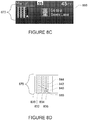
- FIGURES 8C and 8D are examples of display 860 depicting autodrive information 870.
- display 860 includes map information for the same autodrive zone as display 810.
- FIGURE 8D includes only a portion of display 860 depicting autodrive information 870.
- display 860 may be shown to a driver via any number of different types of displays, including, for example, display 152.
- Display 860 of FIGURE 8A is an example of information which may be displayed to a driver when vehicle 101 is ready to be driven in an autonomous driving mode or is being driven in the autonomous driving mode.
- computer 110 may display lane information for only those lanes having the same direction of traffic. For example, as shown in FIGURE 9 , vehicle 101 is currently being driven in lane 510 of detailed map information 600. In this example, lanes in autodrive zone 610 may have a same direction of traffic as lane 510 while lanes in autodrive zone 620 may have a different direction of traffic as lane 510.
- autodrive information 810 and 870 includes lanes 830, 832, 834, and 836, all of which are associated with the same direction of traffic.
- lanes 830, 832, and 834 include autodrive indicators, here boxes 840, 842, and 844, respectively. These autodrive indicators may be shown in a different color or otherwise highlighted as compared to lane 836 to indicate that lane 836 is currently not available for the autonomous driving mode, even though it may be an autodrive lane according to the detailed map information 136. In this regard, lane 836 may otherwise be available for driving, but there is some reason (such as those described above) which prevents the vehicle from using the autonomous driving mode in lane 836.
- mile data 1260L includes an icon 1268L.
- This icon may indicate the reason for the length of the lane available for the autonomous driving mode.
- the icon represents a construction worker, indicating that in 10 miles lane 1234 will not be available for the autonomous driving mode due to construction.
- Other icons may also be used to indicate other reasons.
- icons may represent turns or merges or other maneuvers required for a particular route.
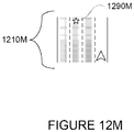
- FIGURE 12M includes autodrive information 1210M which is yet another example of how the longest lane available for the autonomous driving mode may be identified.
- the longest lane identifier is depicted as a star icon 1290M.
- the star icon 1290M may suggest to the driver the best lane for initiating the autonomous driving mode. Again, other icons may be used to identify the longest lane available for autonomous driving.
- One of the simplest driving tasks for an autonomous vehicle is to stay in a single lane without stopping.
- the driver may maneuver the vehicle to the best lane for autonomous driving. This may, in turn, allow the vehicle to avoid problem situations such as merges, construction, narrow lanes, exit only lanes, etc.
Landscapes
- Engineering & Computer Science (AREA)
- Transportation (AREA)
- Mechanical Engineering (AREA)
- Physics & Mathematics (AREA)
- General Physics & Mathematics (AREA)
- Radar, Positioning & Navigation (AREA)
- Remote Sensing (AREA)
- Chemical & Material Sciences (AREA)
- Combustion & Propulsion (AREA)
- Automation & Control Theory (AREA)
- Human Computer Interaction (AREA)
- Navigation (AREA)
- Aviation & Aerospace Engineering (AREA)
- Traffic Control Systems (AREA)
- Control Of Driving Devices And Active Controlling Of Vehicle (AREA)
Abstract
Description
- The present application is a continuation of
U.S. Patent Application No. 13/792,304, filed on March 11, 2013 U.S. Provisional Patent Application No. 61/731,701 filed November 30, 2012 - Autonomous vehicles use various computing systems to aid in the transport of passengers from one location to another. Some autonomous vehicles may require some initial input or continuous input from an operator, such as a pilot, driver, or passenger. Other systems, for example autopilot systems, may be used only when the system has been engaged, which permits the operator to switch from a manual driving mode (where the operator exercises a high degree of control over the movement of the vehicle) to an autonomous driving mode (where the vehicle essentially drives itself) to modes that lie somewhere in between.
- Such vehicles may rely on highly-detailed maps in order to make driving decisions. In some examples, these maps may include information about the location of lanes for driving. Some non-autonomous navigation systems provide users with instructions for driving a vehicle along a route between locations. These systems may also display information regarding lanes and also highlight or otherwise indicate which lane is appropriate for a particular route. For example, if the route includes a turn, these systems may indicate a specific lane for the vehicle in order to position the vehicle for the turn.
- One aspect of the disclosure provides a method. The method includes receiving data from a geographic position component; determining a current location of a vehicle from the received data; using the current location to access detailed map information identifying the location of autodrive lanes, wherein each autodrive lane is a lane of a roadway pre-approved for an autonomous driving mode of the vehicle, the autonomous driving mode allowing a driver to relinquish control of the vehicle to a computer; identifying one or more of the autodrive lanes currently available for autonomous driving; using, by a processor, the identified one or more autodrive lanes to generate autodrive information; generating, by the processor, display information based on the autodrive information, the display information including lanes and identifying which of the lanes are of the one or more autodrive lanes; and displaying, on a display of the vehicle, the display information.
- In one example, the method also includes determining which lane the vehicle is currently located, and the display information includes an indicator indicating the lane in which the vehicle is currently located. In another example, the method also includes determining whether the vehicle is currently in a particular one of the one or more of the autodrive lanes; when the vehicle is currently in the particular autodrive lane, determining a remaining distance in the particular autodrive lane available for the autonomous driving mode based on the detailed map information; and wherein the display information includes distance data indicating the remaining distance. In this example, the method also includes generating a route for navigating the vehicle and determining the remaining distance is also based on the route. The method also includes identifying an icon for the remaining distance based on the route, and wherein the display information includes the icon for the remaining distance. Alternatively, determining the remaining distance is also based on the traffic information, the method also includes identifying an icon for the remaining distance based on the traffic information, and the display information includes the icon for the remaining distance.
- In another example, the method also includes determining, for each of the one or more of the autodrive lanes, a remaining distance available for the autonomous driving mode; identifying, based on the determinate remaining distances, a longest lane available for the autonomous driving mode; and the display information includes an indicator identifying the longest lane available for the autonomous driving mode. In another example, the lanes of the display information include at least one lane that is not available for autonomous driving, and the lanes of the one or more autodrive lanes are depicted in a color different from a color of the at least one lane that is not available for autonomous driving.
- Another aspect of the disclosure provides a system. The system includes a display for displaying information to a driver and a processor. The processor is configured to receive data from a geographic position component; determine a current location of a vehicle from the received data; use the current location to access detailed map information identifying the location of autodrive lanes, wherein each autodrive lane is a lane of a roadway pre-approved for an autonomous driving mode of the vehicle, the autonomous driving mode allowing a driver to relinquish control of the vehicle to a computer; identify one or more of the autodrive lanes currently available for autonomous driving; use the identified one or more autodrive lanes to generate autodrive information; generate display information based on the autodrive information, the display information including lanes and identifying which of the lanes are of the one or more autodrive lanes; and displaying, on the display, the display information.
- In one example, the processor is also configured to determine in which lane the vehicle is currently located, and the display information includes an indicator indicating the lane in which the vehicle is currently located. In another example, the processor is also configured to determine whether the vehicle is currently in a particular one of the one or more of the autodrive lanes; when the vehicle is currently in the particular autodrive lane, determine a remaining distance in the particular autodrive lane available for the autonomous driving mode based on the detailed map information; and the display information includes distance data indicating the remaining distance. In this example, the processor is also configured to generate a route for navigating the vehicle, and determining the remaining distance is also based on the route. The processor is also configured to identify an icon for the remaining distance based on the route, and the display information includes the icon for the remaining distance. Alternatively, determining the remaining distance is also based on the traffic information, and the processor is also configured to identify an icon for the remaining distance based on the traffic information, and the display information includes the icon for the remaining distance.
- In another example, the processor is also configured to determine, for each of the one or more of the autodrive lanes, a remaining distance available for the autonomous driving mode; and identify, based on the determinate remaining distances, a longest lane available for the autonomous driving mode; and the display information includes an indicator identifying the longest lane available for the autonomous driving mode. In another example, the lanes of the display information include at least one lane that is not available for autonomous driving, and the lanes of the one or more autodrive lanes are depicted in a color different from a color of the at least one lane that is not available for autonomous driving.
- A further aspect of the disclosure provides a non-transitory, tangible computer-readable storage medium on which computer readable instructions of a program are stored. The instructions, when executed by a processor, cause the processor to perform a method. The method includes receiving data from a geographic position component; determining a current location of a vehicle from the received data; using the current location to access detailed map information identifying the location of autodrive lanes, wherein each autodrive lane is a lane of a roadway pre-approved for an autonomous driving mode of the vehicle, the autonomous driving mode allowing a driver to relinquish control of the vehicle to a computer; identifying one or more of the autodrive lanes currently available for autonomous driving; using the identified one or more autodrive lanes to generate autodrive information; generating display information based on the autodrive information, the display information including lanes and identifying which of the lanes are of the one or more autodrive lanes; and displaying, on a display of the vehicle, the display information.
- In one example, the method also includes determining which lane the vehicle is currently located, and the display information includes an indicator indicating the lane in which the vehicle is currently located. In another example, the method also includes determining whether the vehicle is currently in a particular one of the one or more of the autodrive lanes; when the vehicle is currently in the particular autodrive lane, determining a remaining distance in the particular autodrive lane available for the autonomous driving mode based on the detailed map information; and the display information includes distance data indicating the remaining distance. In this example, the method also includes generating a route for navigating the vehicle, and determining the remaining distance is also based on the route. The method also includes identifying an icon for the remaining distance based on the route, and wherein the display information includes the icon for the remaining distance. Alternatively, determining the remaining distance is also based on the traffic information, and the method also includes identifying an icon for the remaining distance based on the traffic information, and the display information includes the icon for the remaining distance.
- In another example, the method also includes determining, for each of the one or more of the autodrive lanes, a remaining distance available for the autonomous driving mode; identifying, based on the determinate remaining distances, a longest lane available for the autonomous driving mode; and the display information includes an indicator identifying the longest lane available for the autonomous driving mode. In another example, the lanes of the display information include at least one lane that is not available for autonomous driving, and wherein the lanes of the one or more autodrive lanes are depicted in a color different from a color of the at least one lane that is not available for autonomous driving.
-
-
FIGURE 1 is a functional diagram of a system in accordance with aspects of the disclosure. -
FIGURE 2 is an interior of an autonomous vehicle in accordance with aspects of the disclosure. -
FIGURE 3 is an exterior of an autonomous vehicle in accordance with aspects of the disclosure. -
FIGURE 4 is an illustration of a highway used by way of example in accordance with aspects of the disclosure. -
FIGURE 5 is an example of map information in accordance with aspects of the disclosure. -
FIGURE 6 is another example of map information in accordance with aspects of the disclosure. -
FIGURE 7A is a pictorial diagram of a system in accordance with aspects of the disclosure. -
FIGURE 7B is a functional diagram of the system ofFIGURE 7A . -
FIGURES 8A-8D are examples of displays for autodrive information in accordance with aspects of the disclosure. -
FIGURE 9 is an example of map information and location data in accordance with aspects of the disclosure. -
FIGURES 10A and 10B are examples of displays for autodrive information in accordance with aspects of the disclosure. -
FIGURES 11A and 11B are additional examples of displays for autodrive information in accordance with aspects of the disclosure. -
FIGURES 12A-12M are further examples of displays for autodrive information in accordance with aspects of the disclosure. -
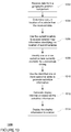
FIGURE 13 is a flow diagram in accordance with aspects of the disclosure. - In one aspect of the disclosure a computer may receive data from a geographic position component. The received data may be used to determine a current location of a vehicle. The current location may be used to access detailed map information and identify the location of "autodrive" lanes. As described in more detail below, autodrive lanes include lanes which are pre-approved for an autonomous driving mode where a driver is able to relinquish control of a vehicle to a computer.
- The computer then identifies one or more of the autodrive lanes which are currently available for autonomous driving. The one or more of the identified autodrive lanes are used to generate autodrive information. As described in more detail below, the autodrive information may include information such as a number of lanes, which of those lanes is available or not available for an autonomous driving mode, the current location of the vehicle with regard to the lanes, whether the vehicle is currently in an available autodrive lane or a non-autodrive lane, the remaining distance of the lanes (such as the lane in which the vehicle is currently) for the autonomous driving mode, the longest lane available for the autonomous driving mode, etc. The computer may then generate display information based on the autodrive information and display the display information to a driver.
- As shown in
FIGURE 1 , anautonomous driving system 100 may include avehicle 101 with various components. While certain aspects of the disclosure are particularly useful in connection with specific types of vehicles, the vehicle may be any type of vehicle including, but not limited to, cars, trucks, motorcycles, busses, boats, airplanes, helicopters, lawnmowers, recreational vehicles, amusement park vehicles, farm equipment, construction equipment, trams, golf carts, trains, and trolleys. The vehicle may have one or more computers, such ascomputer 110 containing aprocessor 120,memory 130 and other components typically present in general purpose computers. - The
memory 130 stores information accessible byprocessor 120, includinginstructions 132 anddata 134 that may be executed or otherwise used by theprocessor 120. Thememory 130 may be of any type capable of storing information accessible by the processor, including a computer-readable medium, or other medium that stores data that may be read with the aid of an electronic device, such as a hard-drive, memory card, ROM, RAM, DVD or other optical disks, as well as other write-capable and read-only memories. Systems and methods may include different combinations of the foregoing, whereby different portions of the instructions and data are stored on different types of media. - The
instructions 132 may be any set of instructions to be executed directly (such as machine code) or indirectly (such as scripts) by the processor. For example, the instructions may be stored as computer code on the computer-readable medium. In that regard, the terms "instructions" and "programs" may be used interchangeably herein. The instructions may be stored in object code format for direct processing by the processor, or in any other computer language including scripts or collections of independent source code modules that are interpreted on demand or compiled in advance. Functions, methods and routines of the instructions are explained in more detail below. - The
data 134 may be retrieved, stored or modified byprocessor 120 in accordance with theinstructions 132. For instance, although the claimed subject matter is not limited by any particular data structure, the data may be stored in computer registers, in a relational database as a table having a plurality of different fields and records, XML documents or flat files. The data may also be formatted in any computer-readable format. By further way of example only, image data may be stored as bitmaps including of grids of pixels that are stored in accordance with formats that are compressed or uncompressed, lossless (e.g., BMP) or lossy (e.g., JPEG), and bitmap or vector-based (e.g., SVG), as well as computer instructions for drawing graphics. The data may include any information sufficient to identify the relevant information, such as numbers, descriptive text, proprietary codes, references to data stored in other areas of the same memory or different memories (including other network locations) or information that is used by a function to calculate the relevant data. - The
processor 120 may be any conventional processor, such as commercially available CPUs. Alternatively, the processor may be a dedicated device such as an ASIC or other hardware-based processor. AlthoughFIGURE 1 functionally illustrates the processor, memory, and other elements ofcomputer 110 as being within the same block, it will be understood by those of ordinary skill in the art that the processor, computer, or memory may actually include multiple processors, computers, or memories that may or may not be stored within the same physical housing. For example, memory may be a hard drive or other storage media located in a housing different from that ofcomputer 110. Accordingly, references to a processor or computer will be understood to include references to a collection of processors or computers or memories that may or may not operate in parallel. Rather than using a single processor to perform the steps described herein, some of the components, such as steering components and deceleration components, may each have their own processor that only performs calculations related to the component's specific function. - In various aspects described herein, the processor may be located remote from the vehicle and communicate with the vehicle wirelessly. In other aspects, some of the processes described herein are executed on a processor disposed within the vehicle and others by a remote processor, including taking the steps necessary to execute a single maneuver.
-
Computer 110 may include all of the components normally used in connection with a computer such as a central processing unit (CPU), memory (e.g., RAM and internal hard drives) storingdata 134 and instructions such as a web browser, an electronic display 152 (e.g., a monitor having a screen, a small LCD touch-screen or any other electrical device that is operable to display information), user input 150 (e.g., a mouse, keyboard, touch screen and/or microphone), as well as various sensors (e.g., a video camera) for gathering explicit (e.g., a gesture) or implicit (e.g., "the person is asleep") information about the states and desires of a person. - In one example,
computer 110 may be an autonomous driving computing system incorporated intovehicle 101.FIGURE 2 depicts an exemplary design of the interior of an autonomous vehicle. The autonomous vehicle may include all of the features of a non-autonomous vehicle, for example: a steering apparatus, such assteering wheel 210; a navigation display apparatus, such as navigation display 215 (which may be a part of electronic display 152); and a gear selector apparatus, such asgear shifter 220. The vehicle may also have various user input devices 140 in addition to the foregoing, such as touch screen 217 (again, which may be a part of electronic display 152), orbutton inputs 219, for activating or deactivating one or more autonomous driving modes and for enabling a driver orpassenger 290 to provide information, such as a navigation destination, to theautonomous driving computer 110. - The autonomous driving computing system may capable of communicating with various components of the vehicle. For example, returning to
FIGURE 1 ,computer 110 may be in communication with the vehicle'scentral processor 160 and may send and receive information from the various systems ofvehicle 101, for example thebraking system 180,acceleration system 182, signalingsystem 184, andnavigation system 186 systems in order to control the movement, speed, etc. ofvehicle 101. In one example, the vehicle'scentral processor 160 may perform all of the functions of a central processor in a non-autonomous computer. In another example,processor - In addition, when engaged,
computer 110 may control some or all of these functions ofvehicle 101 and thus be fully or partially autonomous. It will be understood that although various systems andcomputer 110 are shown withinvehicle 101, these elements may be external tovehicle 101 or physically separated by large distances. - The vehicle may also include a
geographic position component 144 in communication withcomputer 110 for determining the geographic location of the device. For example, the position component may include a GPS receiver to determine the device's latitude, longitude and/or altitude position. Other location systems such as laser-based localization systems, inertial-aided GPS, or camera-based localization may also be used to identify the location of the vehicle. The location of the vehicle may include an absolute geographical location, such as latitude, longitude, and altitude as well as relative location information, such as location relative to other cars immediately around it which can often be determined with better accuracy than absolute geographical location. - The vehicle may also include other devices in communication with
computer 110, such as an accelerometer, gyroscope or another direction/speed detection device 146 to determine the direction and speed of the vehicle or changes thereto. By way of example only,acceleration device 146 may determine its pitch, yaw or roll (or changes thereto) relative to the direction of gravity or a plane perpendicular thereto. The device may also track increases or decreases in speed and the direction of such changes. The device's provision of location and orientation data as set forth herein may be provided automatically to the user,computer 110, other computers and combinations of the foregoing. - The
computer 110 may control the direction and speed of the vehicle by controlling various components. By way of example, if the vehicle is operating in a completely autonomous driving mode,computer 110 may cause the vehicle to accelerate (e.g., by increasing fuel or other energy provided to the engine), decelerate (e.g., by decreasing the fuel supplied to the engine or by applying brakes) and change direction (e.g., by turning the front two wheels). - The vehicle may also include components for detecting objects external to the vehicle such as other vehicles, obstacles in the roadway, traffic signals, signs, trees, etc. The
detection system 154 may include lasers, sonar, radar, cameras or any other detection devices which record data which may be processed bycomputer 110. For example, if the vehicle is a small passenger vehicle, the car may include a laser mounted on the roof or other convenient location. - As shown in
FIGURE 3 ,vehicle 101 may include a small passengervehicle having lasers laser 310 may have a range of approximately 150 meters, a thirty degree vertical field of view, and approximately a thirty degree horizontal field of view.Laser 311 may have a range of approximately 50-80 meters, a thirty degree vertical field of view, and a 360 degree horizontal field of view. The lasers may provide the vehicle with range and intensity information which the computer may use to identify the location and distance of various objects. In one aspect, the lasers may measure the distance between the vehicle and the object surfaces facing the vehicle by spinning on its axis and changing its pitch. - The vehicle may also include various radar detection units, such as those used for adaptive cruise control systems. The radar detection units may be located on the front and back of the car as well as on either side of the front bumper. As shown in the example of
FIGURE 3 ,vehicle 101 includes radar detection units 320-323 located on the side (only one side being shown), front and rear of the vehicle. In this example, each of these radar detection units may have a range of approximately 200 meters for an approximately 18 degree field of view as well as a range of approximately 60 meters for an approximately 56 degree field of view. - In another example, a variety of cameras may be mounted on the vehicle. The cameras may be mounted at predetermined distances so that the parallax from the images of 2 or more cameras may be used to compute the distance to various objects. As shown in
FIGURE 3 ,vehicle 101 may include 2 cameras 330-331 mounted under awindshield 340 near the rear view mirror (not shown). Camera 330 may include a range of approximately 200 meters and an approximately 30 degree horizontal field of view, while camera 331 may include a range of approximately 100 meters and an approximately 60 degree horizontal field of view. - In addition to the sensors described above, the computer may also use input from other sensors and features typical to non-autonomous vehicles. For example, these other sensors and features may include tire pressure sensors, engine temperature sensors, brake heat sensors, break pad status sensors, tire tread sensors, fuel sensors, oil level and quality sensors, air quality sensors (for detecting temperature, humidity, or particulates in the air), door sensors, lights, wipers, etc. This information may be provided directly from these sensors and features or via the vehicle's
central processor 160. - Many of these sensors provide data that is processed by the computer in real-time, that is, the sensors may continuously update their output to reflect the environment being sensed at or over a range of time, and continuously or as-demanded provide that updated output to the computer so that the computer can determine whether the vehicle's then-current direction or speed should be modified in response to the sensed environment.
- In addition to processing data provided by the various sensors, the computer may rely on environmental data that was obtained at a previous point in time and is expected to persist regardless of the vehicle's presence in the environment. For example, returning to
FIGURE 1 ,data 134 may includedetailed map information 136, e.g., highly detailed maps identifying the shape and elevation of roadways, lane lines, intersections, crosswalks, speed limits, traffic signals, buildings, signs, real time traffic information, vegetation, or other such objects and information. For example, the map information may include explicit speed limit information associated with various roadway segments. The speed limit data may be entered manually or scanned from previously taken images of a speed limit sign using, for example, optical-character recognition. -
FIGURE 4 is an example of ahighway 400. In this example,highway 400 includes 3 northbound lanes 410-412 and 3 southbound lanes 420-22 defined by broken lane lines 430-33 and solid lane lines 440-43.Highway 400 also includes shoulders 450-51 defined betweensolid lane line 440 andbarrier 460 andsolid lane line 441 andbarrier 461, respectively. Between the northbound and southbound lanes,highway 400 includes a median 470. -
FIGURE 5 is an example ofmap information 500 forhighway 400 ofFIGURE 4 . Map information includes data indicating the location and orientation of the various features ofhighway 400. For example,map information 500 includes northbound lane data 510-512 identifying northbound lanes 410-412 as well as southbound lane data 520-522 identifying southbound lanes 420-22.Map information 500 also includes broken lane line data 530-33 and solid lane line data 540-43 representing broken lane lines 430-33 and solid lane lines 440-43. Shoulders 450-51 are also represented by shoulder data 550-551. Barriers 460-61 are represented by barrier data 560-61, and median 470 is represented bymedian data 570. - The map information may also include three-dimensional terrain maps incorporating one or more of objects listed above. For example, the vehicle may determine that another object, such as a vehicle, is expected to turn based on real-time data (e.g., using its sensors to determine the current geolocation such as a GPS position of another vehicle and whether a turn signal is blinking) and other data (e.g., comparing the GPS position with previously-stored lane-specific map data to determine whether the other vehicle is within a turn lane).
- The
map information 136 may also include autodrive zones such as lanes, roadways, areas, etc. that are currently available for autonomous driving. Autodrive zones may include for examples, areas within the map information which have been pre-approved or otherwise designated for initiating or continuing driving in an autonomous driving mode. These areas may include, for example, specific lanes on a highway, residential streets, etc. In this regard, autodrive zones may include pre-determined autodrive lanes. Areas which may be excluded from autodrive zones may include, by way of example only, acceleration lanes, exit lanes, merges, intersections, toll booths, known construction zones, and school zones and portions of roadways near such areas. Althoughcomputer 110 may restrict initiating the autonomous driving mode in areas which are not designated as autodrive zones, thecomputer 110 may actually be fully capable of maneuvering the vehicle through such areas or actually initiating the autonomous driving mode. - For example,
map information 600 of FIGURE 600 includesmap information 500 and alsoautodrive zones zone 610 includes the southbound lanes 430-32 (represented by southbound lane data 530-32) ofhighway 400 whileautodrive zone 620 includes only a portion of the northbound lanes 420-22 (represented by northbound lane data 520-522) ofhighway 400.Autodrive zone 610 includes the zones of lanes 410-22 (represented by lanes data 510-22); however, in this example, only lanes 410 (510) and 411 (511) includeautodrive lanes autodrive zone 620 includes portions of the zones of lanes 420-22 (represented by lanes 520-22); however, in this example, only lanes 421 (521) and 422 (522) includeautodrive lanes highway 400 are autodrive zones, and not all lanes within autodrive zones are autodrive lanes. - Although the
detailed map information 136 is depicted herein as an image-based map, the map information need not be entirely image based (for example, raster). For example, the map information may include one or more roadgraphs or graph networks of information such as roads, lanes, intersections, and the connections between these features. Each feature may be stored as graph data and may be associated with information such as a geographic location whether or not it is linked to other related features. For example, a stop sign may be linked to a road and an intersection. In some examples, the associated data may include grid-based indices of a roadgraph to promote efficient lookup of certain roadgraph features. -
Computer 110 may also receive or transfer information to and from other computers. For example, the map information stored by computer 110 (such as the examples ofmap information FIGURES 5 and6 ) may be received or transferred from other computers and/or the sensor data collected from the sensors ofvehicle 101 may be transferred to another computer for processing as described herein. As shown inFIGURES 7A and 7B , data fromcomputer 110 may be transmitted via a network tocomputer 720 for further processing. - The network, and intervening nodes, may include various configurations and protocols including the Internet, World Wide Web, intranets, virtual private networks, wide area networks, local networks, private networks using communication protocols proprietary to one or more companies, Ethernet, WiFi and HTTP, and various combinations of the foregoing. Such communication may be facilitated by any device capable of transmitting data to and from other computers, such as modems and wireless interfaces. In another example, data may be transferred by storing it on memory which may be accessed by or connected to
computers - In one example,
computer 720 may include a server having a plurality of computers, e.g., a load balanced server farm, that exchange information with different nodes of a network for the purpose of receiving, processing and transmitting the data to and fromcomputer 110. The server may be configured similarly to thecomputer 110, with aprocessor 730,memory 740,instructions 750, anddata 760. - Returning to
FIGURE 1 ,computer 110 may accessautodrive display data 138 in order to display information relating to autodrive zones and/or autodrive lanes. As described in more detail below, theautodrive display data 138 may include display data for displaying the relative location, distance, availability, etc. of autodrive lanes. - In addition to the operations described above and illustrated in the figures, various operations will now be described. It should be understood that the following operations do not have to be performed in the precise order described below. Rather, various steps can be handled in a different order or simultaneously, and steps may also be added or omitted.
- Aspects of the present disclosure relate generally to identifying and displaying areas that are available for autonomous driving. In some examples,
vehicle 101 may already be driving in an autonomous driving mode, while in other examples,vehicle 101 may be driving in a manual driving mode. While in either mode,computer 110 may useelectronic display 152 to provide information to the driver regarding autodrive zones as well as autodrive lanes. - In one example,
computer 110 may use data fromgeographic position component 144 to determine a current location ofvehicle 101. The current location ofvehicle 101 may then be used to access a relevant portion ofdetailed map information 160. This may include accessing information regarding autodrive zones and autodrive lanes. Depending upon the characteristics of the autodrive zones and autodrive data, and in some examples, a route selected by the driver,computer 110 may use autodrive display data to generate a display of relevant autodrive information. - For example,
computer 110 may determine whether the vehicle is within an autodrive zone. If not, the autonomous driving mode may not be available to a driver of the vehicle. If the vehicle is within an autodrive zone,computer 110 may determine whether there are any available autodrive lanes in that autodrive zones. - An autodrive lane may be indicated as present in the
detailed map information 136 as described above, but for some reason may not be available for the autonomous driving mode. Examples of such reasons may include where there is not enough of the autodrive lane available (e.g. there is only a half mile of roadway where the minimum to indicate an autodrive lane is one mile) as well as where there is an upcoming acceleration lane, exit lane, merge, intersection, toll booth, known construction zone, school zone, etc. The availability of an autodrive lane may also be based on a route selected by the driver. For example, if a driver inputs a destination and routing to that location would require the vehicle to pass through an area associated with any of the reasons above or to leave a particular lane to make a turn, this may be another reason why an autodrive lane included indetailed map information 136 is currently unavailable. - As noted above, once the autodrive information, including lanes available and not available for autonomous driving, is determined by
computer 110,computer 110 may generate a display based on the autodrive information using theautodrive display data 138.FIGURES 8A and 8B are example ofdisplay 810 depictingautodrive information 820.FIGURE 8B includes only a portion ofdisplay 810 depictingautodrive information 820.Display 810 may be shown to a driver via any number of different types of displays, including, for example,display 152. Display 810 ofFIGURE 8A is an example of information, includingautodrive information 820, that may be displayed to a driver whenvehicle 101 is being driven in the manual driving mode. -
FIGURES 8C and 8D are examples ofdisplay 860 depictingautodrive information 870. In this example,display 860 includes map information for the same autodrive zone asdisplay 810.FIGURE 8D includes only a portion ofdisplay 860 depictingautodrive information 870. As withdisplay 810,display 860 may be shown to a driver via any number of different types of displays, including, for example,display 152. Display 860 ofFIGURE 8A is an example of information which may be displayed to a driver whenvehicle 101 is ready to be driven in an autonomous driving mode or is being driven in the autonomous driving mode. - If the roadway includes multiple lanes,
computer 110 may display lane information for only those lanes having the same direction of traffic. For example, as shown inFIGURE 9 ,vehicle 101 is currently being driven inlane 510 ofdetailed map information 600. In this example, lanes inautodrive zone 610 may have a same direction of traffic aslane 510 while lanes inautodrive zone 620 may have a different direction of traffic aslane 510. Returning toFIGURES 8B and8D ,autodrive information lanes - The displayed autodrive information may also visually distinguish between lanes that are currently available for autonomous driving mode from those that are not. For example, the display may include indicators which identify particular lanes as autodrive lanes or other lanes as not available for autonomous driving mode. As noted above, in some examples, a lane may be an autodrive lane according to
detailed map information 136, however for some other reason, the lane is not shown as such because it is not available for the autonomous driving mode. - As shown in
FIGURES 8B and8D ,lanes boxes lane 836 to indicate thatlane 836 is currently not available for the autonomous driving mode, even though it may be an autodrive lane according to thedetailed map information 136. In this regard,lane 836 may otherwise be available for driving, but there is some reason (such as those described above) which prevents the vehicle from using the autonomous driving mode inlane 836. - The displayed autodrive information may also include an indicator of the position of a lane (autodrive or not) currently occupied by the vehicle. In this regard,
computer 110 may use the current location ofvehicle 101 to determine where to indicate the current location of the vehicle in the autodrive information. For example inFIGURE 8B , a vehicle location indicator, herearrow 850, depicts the current location ofvehicle 101 inlane 836. Although shown as an arrow, other indicators such as chevrons, pointers, etc. may also be used. In this example,lane 860 is not an autodrive lane as there is no autodrive indicator associated with that lane. In the example ofFIGURE 8D ,arrow 880, depicts the current location ofvehicle 101 inlane 834. In this example,lane 834 is an autodrive lane as it includesbox 844. - In addition, if the lane currently occupied by the vehicle, as indicated by the vehicle location indicator, is an autodrive lane, the display may include information indicating how much further the vehicle may either begin or continue driving in the autonomous driving mode in that particular lane as determined by
computer 110. This determination may be made bycomputer 110 based on the detailed map information (e.g. this lane continues only for another so many miles, there is a merge into this lane in so many miles which the vehicle should avoid driving in autonomous driving mode, etc.) or may be based on the location of the vehicle relative to a route (e.g. where a route would require the vehicle to exit the lane, etc.). -
FIGURE 10A is an example ofautodrive information 1010 which depictslanes Lanes autodrive indicators Vehicle location indicator 1050 indicates the current location ofvehicle 101 inlane 1034. This example also includesmile data 1060 indicating thatvehicle 101 has 3 more miles of this lane in which to drive in the autonomous driving mode. Here,mile data 1060 is displayed belowlanes - The display may also display information indicating the remaining autodrive distance in other lanes as well as the lane with the greatest remaining autodrive distance. For example,
computer 110 may use the detailed map information (e.g. this lane continues only for another so many miles, there is a merge into this lane in so many miles which the vehicle should avoid driving in autonomous driving mode, etc.) or the location of the vehicle relative to a route (e.g. where a route would require the vehicle to exit the lane, etc.) to determine whether and how much distance is available for the autonomous driving mode in each of the lanes of the autodrive information. Thus,computer 110 may also determine in which lane has the greatest distance available for the autonomous driving mode. - This information may then be incorporated in the autodrive information and displayed to the driver. In one example, the display of the autodrive information may include a longest lane indicator having a bracket and an arrow pointing towards the longest lane available for autonomous driving mode as well as information indicating the number of miles remaining in the longest lane.
- For example,
FIGURE 10B is an example ofautodrive information 1070 which depictslanes Lanes autodrive indicators FIGURE 10A ). Again,vehicle location indicator 1050 indicates the current location ofvehicle 101 inlane 1034.Mile data 1060 indicates thatvehicle 101 has 3 more miles of this lane in which to drive in the autonomous driving mode. In addition, this example includeslongest lane indicator 1090 havingbracket 1092,arrow 1094, andmile data 1096 indicating that there are 7 more miles oflane 1030 in which to drive in the autonomous driving mode. In this example, the longest lane indicator is displayed abovelanes Arrow 1094 indicates that the longest length, here 7 miles, applies tolane 1030. The longest lane indicator also implies that the other lanes available for autonomous driving, in the example ofFIGURE 10B lanes -
FIGURES 11A and 11B depict examples ofautodrive information longest lane indicators brackets brackets mile data brackets FIGURE 11A ,autodrive information 1110 includesvehicle location indicator 1150. This indicator is associated with a lane which is also one of the longest lanes. However, in the example ofFIGURE 11B , the autodrive information also includesmile data 1160 which indicates thatvehicle 101 has 13 more miles of this lane in which to drive in the autonomous driving mode which is different from the lanes associated with the longest lane indicators. - Although the examples described above include specific configurations, autodrive information may be presented in many other ways consistent with the present disclosure.
FIGURES 12A-12M are examples ofautodrive information 1210A-1210M, which depict various alternatives for displaying autodrive information. Although specifically identified in reference toFIGURE 12A , each of these examples includes 4 lanes; 1230, 1232, 1234, and 1236. There of these lanes includeautodrive indicators lane 1236 is currently unavailable for autonomous driving mode. In the example ofFIGURE 12A ,vehicle location indicator 1250 is depicted inlane 1236. However, this same location indicator is also shown inlane 1234 in other examples ofFIGURES 12D ,12H, and 12I and inlane 1236 in the example ofFIGURE 12M . -
Autonomous information 1210A ofFIGURE 12A uses shading to indicate the longest lane available for autonomous driving mode. For example,lane 1232 has more miles available for autonomous driving mode thanlanes autodrive lane indicators Autodrive indicator 1242 oflane 1232 is shown as solid to indicate that this lane is the longest lane available for autonomous driving mode. This example also includesmile data 1260A indicating the number of miles available for autonomous driving mode inlane 1234 as well asmile data 1296A indicating the number of miles available for autonomous driving mode inlane 1232. In this example, themile data box icons lanes -
FIGURE 12B depicts an example ofautodrive information 1210B where thelongest lane indicator 1290B having abracket 1292B and anarrow 1294B. However, in this example, thebracket 1292B is above each of the displayed lanes and simply not connecting the longest lanes as shown in the examples ofFIGURES 11A and 11B . -
Autodrive information 1210C ofFIGURE 12C is similar to the example ofFIGURE 12B . In this example,longest lane indicator 1290C includes the text "longest lane" abovebracket 1292C andarrow 1294C. In addition, this example includesmile data 1260C identifying the length oflane 1234 available for the autonomous driving mode. - In the example of
FIGURE 12D ,autodrive information 1210D includes two longest lanes. Thus, here there are twoarrows 1294D-1 and 1294D-2 and the text "longest lanes" abovebracket 1292D. This example also includesmile data 1260D identifying the length oflane 1232 available for the autonomous driving mode. -
FIGURE 12E is an example ofautodrive information 1210E wherevehicle 101 is not currently located in an autodrive lane and presumably not in the autonomous driving mode. As described above with regard toFIGURE 12A ,lane 1236 is not an autodrive lane. In this example, thelongest lane indicator 1290E includes a bracket 1292E, anarrow 1294E, and the text "longest lane." There is also anarrow 1298E encouraging the driver to move the vehicle fromlane 1236 tolane 1232 to which arrow 1292E is directed. -
Autodrive information 1210F ofFIGURE 12F depicts another example of a longest lane identifier wherevehicle 101 is currently not located in an autodrive lane and presumably not in the autonomous driving mode. In this example,box 1242 is given athicker outline 1292F thanboxes thicker outline 1292F indicates thatlane 1232 is the longest lane available for autonomous driving mode. - In the example of 1210G,
autodrive information 1210G indicates thatvehicle 101 is currently driving in an autodrive lane. Here,vehicle 101 is inlane 1236 andmile data 1260G indicates that there are 7 miles remaining for the autonomous driving mode (though this example does not use the text "miles"). As with the example ofFIGURE 12F ,autodrive information 1210G uses athicker outline 1292G to identify the longest lane available for the autonomous driving mode. -
FIGURE 12H is again similar toFIGURE 12G . In this example,autodrive information 1210H indicates thatvehicle 101 has moved tolane 1232, identified bythicker outline 1292H as the longest lane. In this example, althoughlane 1232 is identified as the longest lane,mile data 1260H/1296H is depicted below the lanes rather than above becausevehicle 101 is currently driving in the longest lane available for autonomous driving mode. - Autodrive information 1210I of
FIGURE 12I includes longest lane indicator 1290I having an arrow 1294I and mile data 1296I. Longest lane indicator 1290I indicates thatlane 1236 is the longest lane available for autonomous driving mode. This example does not include a bracket above any of the lanes, nor does it include mile data forlane 1232 in whichvehicle 101 is currently driving (as identified by arrow 1250). - The example of
autodrive information 1210J ofFIGURE 12J is similar to the example ofFIGURE 12A . However, in this example, rather than depictingboxes lanes box 1242 oflane 1232. Thus, in this example,lane 1232 is identified as the longest lane currently available for autonomous driving mode as its box is shown in a different shade or color from the boxes of the other lanes available for the autonomous driving mode. Again, as with the other examples described above,lane 1236 ofFIGURE 12J does not include a box as it is unavailable for the autonomous driving mode. In addition, themile data box icons lanes - As with
autodrive information 1210J, the example ofautodrive information 1210K ofFIGURE 12K uses the color or shade ofbox 1232K to identifylane 1232 as the longest lane available for autonomous driving. However, in this example, no mile data is displayed forbox 1232K.Vehicle 101 is currently driving inlane 1234. This example includesmile data 1260K which identifies the remaining available miles for autonomous driving mode inlane 1234. In this example, the mile data includes "Length:" to clearly identify the number of remaining miles.Mile data 1260K is displayed below abracket 1262K shown below the lanes. - The example of
autodrive information 1210L ofFIGURE 12L is similar to that ofFIGURE 12K . However, inFIGURE 12L , rather than using the text "Length:,"mile data 1260L includes anicon 1268L. This icon may indicate the reason for the length of the lane available for the autonomous driving mode. Here, the icon represents a construction worker, indicating that in 10miles lane 1234 will not be available for the autonomous driving mode due to construction. Other icons may also be used to indicate other reasons. In one example, icons may represent turns or merges or other maneuvers required for a particular route. -
FIGURE 12M includesautodrive information 1210M which is yet another example of how the longest lane available for the autonomous driving mode may be identified. In this example, the longest lane identifier is depicted as astar icon 1290M. Asvehicle 101 is currently located inlane 1236 which is not available for the autonomous driving mode, thestar icon 1290M may suggest to the driver the best lane for initiating the autonomous driving mode. Again, other icons may be used to identify the longest lane available for autonomous driving. - Flow diagram 1300 of
FIGURE 13 is an example of some of the aspects described above which may be performed bycomputer 110. In this example, thecomputer 110 receives data from a geographic position component atblock 1302. The received data is then used to determine a current location of a vehicle atblock 1304. The current location is used to access detailed map information and identify the location of autodrive lanes atblock 1306. As described above, autodrive lanes include lanes which are pre-approved for an autonomous driving mode where a driver is able to relinquish control of a vehicle to a computer, such ascomputer 110. - The computer then identifies one or more of the autodrive lanes currently available for autonomous driving at
block 1308. The identified one or more autodrive lanes are used to generate autodrive information atblock 1310. As described above, with regard toFIGURES 8A-8D ,10A ,10B ,11A ,11B , and12A-12M , the autodrive information may include information such as a number of lanes, which of those lanes is available or not available for autonomous driving mode, the current location of the vehicle with regard to the lanes, whether the vehicle is currently in an available autodrive lane or a non-autodrive lane, the remaining distance of the lanes (such as the lane in which the vehicle is currently) for the autonomous driving mode, the longest lane available for the autonomous driving mode, etc. Thecomputer 110 then generates display information based on the autodrive information and display the display information atblocks - One of the simplest driving tasks for an autonomous vehicle is to stay in a single lane without stopping. By displaying autodrive information as described above, the driver may maneuver the vehicle to the best lane for autonomous driving. This may, in turn, allow the vehicle to avoid problem situations such as merges, construction, narrow lanes, exit only lanes, etc.
- As these and other variations and combinations of the features discussed above can be utilized without departing from the subject matter as defined by the claims, the foregoing description of exemplary embodiments should be taken by way of illustration rather than by way of limitation of the subject matter as defined by the claims. It will also be understood that the provision of the examples described herein (as well as clauses phrased as "such as," "e.g.", "including" and the like) should not be interpreted as limiting the claimed subject matter to the specific examples; rather, the examples are intended to illustrate only some of many possible aspects.
- The present invention enjoys wide industrial applicability including, but not limited to, determining and displaying lanes available for driving by a vehicle in an autonomous driving mode.
- The specification includes the following clauses:
- 1. A method comprising:
- receiving data from a geographic position component;
- determining a current location of a vehicle from the received data;
- using the current location to access detailed map information identifying the location of autodrive lanes, wherein each autodrive lane is a lane of a roadway pre-approved for an autonomous driving mode of the vehicle, the autonomous driving mode allowing a driver to relinquish control of the vehicle to a computer;
- identifying one or more of the autodrive lanes currently available for autonomous driving;
- using, by a processor, the identified one or more autodrive lanes to generate autodrive information;
- generating, by the processor, display information based on the autodrive information, the display information including lanes and identifying which of the lanes are of the one or more autodrive lanes; and
- displaying, on a display of the vehicle, the display information.
- 2. The method of
clause 1, further comprising:- determining which lane the vehicle is currently located, and
- wherein the display information includes an indicator indicating the lane in which the vehicle is currently located.
- 3. The method of
clause 1, further comprising:- determining whether the vehicle is currently in a particular one of the one or more of the autodrive lanes;
- when the vehicle is currently in the particular autodrive lane, determining a remaining distance in the particular autodrive lane available for the autonomous driving mode based on the detailed map information; and
- wherein the display information includes distance data indicating the remaining distance.
- 4. The method of
clause 3, further comprising:- generating a route for navigating the vehicle; and
- wherein determining the remaining distance is further based on the route.
- 5. The method of clause 4, further comprising identifying an icon for the remaining distance based on the route, and wherein the display information includes the icon for the remaining distance.
- 6. The method of
clause 3, wherein determining the remaining distance is further based on the traffic information, and the method further comprises:- identifying an icon for the remaining distance based on the traffic information, and
- wherein the display information includes the icon for the remaining distance.
- 7. The method of
clause 1, further comprising:- determining, for each of the one or more of the autodrive lanes, a remaining distance available for the autonomous driving mode; and
- identifying, based on the determined remaining distances, a longest lane available for the autonomous driving mode,
- wherein the display information includes an indicator identifying the longest lane available for the autonomous driving mode.
- 8. The method of
clause 1, wherein the lanes of the display information include at least one lane that is not available for autonomous driving, and wherein the lanes of the one or more autodrive lanes are depicted in a color different from a color of the at least one lane that is not available for autonomous driving. - 9. A system comprising:
- a display for displaying information to a driver;
- a processor configured to:
- receive data from a geographic position component;
- determine a current location of a vehicle from the received data;
- use the current location to access detailed map information identifying the location of autodrive lanes, wherein each autodrive lane is a lane of a roadway pre-approved for an autonomous driving mode of the vehicle, the autonomous driving mode allowing a driver to relinquish control of the vehicle to a computer;
- identify one or more of the autodrive lanes currently available for autonomous driving;
- use the identified one or more autodrive lanes to generate autodrive information;
- generate display information based on the autodrive information, the display information including lanes and identifying which of the lanes are of the one or more autodrive lanes; and
- displaying, on the display, the display information.
- 10. The system of clause 9, wherein the processor is further configured to:
- determine in which lane the vehicle is currently located, and
- wherein the display information includes an indicator indicating the lane in which the vehicle is currently located.
- 11. The system of
clause 10, wherein the processor is further configured to:- determine whether the vehicle is currently in a particular one of the autodrive lanes;
- when the vehicle is currently in the particular autodrive lane, determine a remaining distance in the particular autodrive lane available for the autonomous driving mode based on the detailed map information; and
- wherein the display information includes distance data indicating the remaining distance.
- 12. The system of clause 11, wherein the processor is further configured to:
- generate a route for navigating the vehicle; and
- wherein determining the remaining distance is further based on the route.
- 13. The system of clause 12, wherein the processor is further configured to identify an icon for the remaining distance based on the route, and the display information includes the icon for the remaining distance.
- 14. The system of clause 11, wherein determining the remaining distance is further based on traffic information, and the processor is further configured to:
- identify an icon for the remaining distance based on the traffic information, and
- wherein the display information includes the icon for the remaining distance.
- 15. The system of clause 14, wherein the processor is further configured to:
- determine, for each of the one or more autodrive lanes, a remaining distance available for the autonomous driving mode; and
- identify, based on the determined remaining distances, a longest lane available for the autonomous driving mode,
- wherein the display information includes an indicator identifying the longest lane available for the autonomous driving mode.
- 16. The system of clause 9, wherein the lanes of the display information include at least one lane that is not available for autonomous driving, and the lanes of the one or more autodrive lanes are depicted in a color different from a color of the at least one lane that is not available for autonomous driving.
- 17. A non-transitory, tangible computer-readable storage medium on which computer readable instructions of a program are stored, the instructions, when executed by a processor, cause the processor to perform a method, the method comprising:
- receiving data from a geographic position
component; - determining a current location of a vehicle from the received data;
- using the current location to access detailed map information identifying the location of autodrive lanes, wherein each autodrive lane is a lane of a roadway pre-approved for an autonomous driving mode of the vehicle, the autonomous driving mode allowing a driver to relinquish control of the vehicle to a computer;
- identifying one or more of the autodrive lanes currently available for autonomous driving;
- using the identified one or more autodrive lanes to generate autodrive information;
- generating display information based on the autodrive information, the display information including lanes and identifying which of the lanes are of the one or more autodrive lanes; and
- displaying, on a display of the vehicle, the display information.
- receiving data from a geographic position
- 18. The medium of clause 17, wherein the method further comprises:
- determining which lane the vehicle is currently located, and
- wherein the display information includes an indicator indicating the lane in which the vehicle is currently located.
- 19. The medium of clause 18, wherein the method further comprises:
- determining whether the vehicle is currently in a particular one of the one or more autodrive lanes;
- when the vehicle is currently in the particular autodrive lane, determining a remaining distance in the particular autodrive lane available for the autonomous driving mode based on the detailed map information; and
- wherein the display information includes distance data indicating the remaining distance.
- 20. The medium of clause 19, wherein the method further comprises:
- generating a route for navigating the vehicle; and
- wherein determining the remaining distance is further based on the route.
- 21. The medium of
clause 20, wherein the method further comprising identifying an icon for the remaining distance based on the route, and wherein the display information includes the icon for the remaining distance. - 22. The medium of clause 21, wherein determining the remaining distance is further based on the traffic information, and the method further comprises:
- identifying an icon for the remaining distance based on the traffic information, and
- wherein the display information includes the icon for the remaining distance.
- 23. The medium of
clause 20, wherein the method further comprises:- determining, for each of the one or more autodrive lanes, a remaining distance available for the autonomous driving mode; and
- identifying, based on the determined remaining distances, a longest lane available for the autonomous driving mode,
- wherein the display information includes an indicator identifying the longest lane available for the autonomous driving mode.
- 24. The method of clause 19, wherein the lanes of the display information include at least one lane that is not available for autonomous driving, and wherein the lanes of the one or more autodrive lanes are depicted in a color different from a color of the at least one lane that is not available for autonomous driving.
Claims (15)
- A computer-implemented method comprising:determining a current location of a vehicle, based on data from a geographic position component;accessing, by one or more processors of the computer using the current location of the vehicle, detailed map information identifying the locations of autodrive lanes, wherein each autodrive lane is a lane of a roadway pre-approved for an autonomous driving mode of the vehicle, the autonomous driving mode allowing a driver to relinquish control of the vehicle to a computer;identifying, by the one or more processors, an autodrive lane based on at least the detailed map information and a route being followed by the vehicle;generating, by the one or more processors, display information including lanes and identifying which of the lanes is the autodrive lane, the display information including a visual indication relating to a distance remaining in the lane for the autonomous driving mode; andproviding, by the one or more processors, the display information for display to the driver.
- The method of claim 1, further comprising displaying the display information when the vehicle is not being operated in the autonomous driving mode.
- The method of claim 1 or claim 2, wherein the visual indication includes an icon representative of a construction zone in order to identify that the distance remaining relates to the construction zone.
- The method of claim 3, wherein the display information includes a visual arrangement where the icon is arranged below a representation of the lanes.
- The method of any preceding claim, wherein the visual indication includes text identifying the distance remaining.
- The method of any preceding claim, wherein the display information includes a visual arrangement where the visual indication is arranged below a representation of the lanes.
- The method of any preceding claim, wherein the display information includes a first display color for the autodrive lane and a second display color for another lane, the first and second display color being different.
- The method of any preceding claim, further comprising a second visual indicator representing a location of the vehicle within one of the lanes.
- The method of claim 1 or claim 2, wherein the visual indication includes an icon representative of a turn required by the route in order to identify that the distance remaining relates to the turn.
- The method of claim 1 or claim 2, wherein the visual indication includes an icon representative of a traffic merge required by the route in order to identify that the distance remaining relates to the traffic merge.
- The method of any preceding claim, wherein the visual indication includes an icon representative of a reasoning for the distance remaining.
- A system comprising at least one computer having one or more processors configured to:determine a current location of a vehicle, based on data from a geographic position component;access, using the current location of the vehicle, detailed map information identifying the locations of autodrive lanes, wherein each autodrive lane is a lane of a roadway pre-approved for an autonomous driving mode of the vehicle, the autonomous driving mode allowing a driver to relinquish control of the vehicle to a computer;identify an autodrive lane based on at least the detailed map information and a route being followed by the vehicle;generate display information including lanes and identifying which of the lanes is the autodrive lane, the display information including a visual indication relating to a distance remaining in the lane for the autonomous driving mode; andprovide the display information for display to the driver.
- The system of claim 12, wherein the one or more processors are further configured to display the display information when the vehicle is not being operated in the autonomous driving mode.
- The system of claim 12 or claim 13, wherein the visual indication includes an icon representative of a construction zone in order to identify that the distance remaining relates to the construction zone, wherein the display information includes a visual arrangement where the icon is arranged below a representation of the autodrive lane and closer to the autodrive lane than any representation of another lane.
- The system of claim 12 or claim 13, wherein the visual indication includes an icon representative of a turn required by the route in order to identify that the distance remaining relates to the turn, or wherein the visual indication includes an icon representative of a traffic merge required by the route in order to identify that the distance remaining relates to the traffic merge.
Applications Claiming Priority (4)
| Application Number | Priority Date | Filing Date | Title |
|---|---|---|---|
| US201261731701P | 2012-11-30 | 2012-11-30 | |
| US13/792,304 US9008961B2 (en) | 2012-11-30 | 2013-03-11 | Determining and displaying auto drive lanes in an autonomous vehicle |
| EP13858416.4A EP2925580B1 (en) | 2012-11-30 | 2013-11-18 | Determining and displaying auto drive lanes in an autonomous vehicle |
| PCT/US2013/070499 WO2014085121A1 (en) | 2012-11-30 | 2013-11-18 | Determining and displaying auto drive lanes in an autonomous vehicle |
Related Parent Applications (2)
| Application Number | Title | Priority Date | Filing Date |
|---|---|---|---|
| EP13858416.4A Division-Into EP2925580B1 (en) | 2012-11-30 | 2013-11-18 | Determining and displaying auto drive lanes in an autonomous vehicle |
| EP13858416.4A Division EP2925580B1 (en) | 2012-11-30 | 2013-11-18 | Determining and displaying auto drive lanes in an autonomous vehicle |
Publications (2)
| Publication Number | Publication Date |
|---|---|
| EP3299238A1 true EP3299238A1 (en) | 2018-03-28 |
| EP3299238B1 EP3299238B1 (en) | 2019-07-03 |
Family
ID=50826242
Family Applications (2)
| Application Number | Title | Priority Date | Filing Date |
|---|---|---|---|
| EP13858416.4A Active EP2925580B1 (en) | 2012-11-30 | 2013-11-18 | Determining and displaying auto drive lanes in an autonomous vehicle |
| EP17188592.4A Active EP3299238B1 (en) | 2012-11-30 | 2013-11-18 | Determining and displaying auto drive lanes in an autonomous vehicle |
Family Applications Before (1)
| Application Number | Title | Priority Date | Filing Date |
|---|---|---|---|
| EP13858416.4A Active EP2925580B1 (en) | 2012-11-30 | 2013-11-18 | Determining and displaying auto drive lanes in an autonomous vehicle |
Country Status (4)
| Country | Link |
|---|---|
| US (7) | US9008961B2 (en) |
| EP (2) | EP2925580B1 (en) |
| CN (2) | CN107792163B (en) |
| WO (1) | WO2014085121A1 (en) |
Cited By (1)
| Publication number | Priority date | Publication date | Assignee | Title |
|---|---|---|---|---|
| EP3798575A1 (en) * | 2019-09-26 | 2021-03-31 | Zenuity AB | Method and system for determining localization of a vehicle on a road |
Families Citing this family (110)
| Publication number | Priority date | Publication date | Assignee | Title |
|---|---|---|---|---|
| DE102012212065A1 (en) * | 2012-07-11 | 2014-01-16 | Robert Bosch Gmbh | Method for operating a driver assistance system for a vehicle and driver assistance system for a vehicle |
| US9008961B2 (en) | 2012-11-30 | 2015-04-14 | Google Inc. | Determining and displaying auto drive lanes in an autonomous vehicle |
| US9280901B2 (en) * | 2013-03-25 | 2016-03-08 | E-Lead Electronic Co., Ltd. | Method for displaying the vehicle safety distance |
| KR101519277B1 (en) * | 2013-12-24 | 2015-05-11 | 현대자동차주식회사 | Apparatus and Method for Recognize of Drive Way of Vehicle |
| US9720411B2 (en) | 2014-02-25 | 2017-08-01 | Ford Global Technologies, Llc | Autonomous driving sensing system and method |
| EP2930081B1 (en) * | 2014-04-08 | 2019-03-27 | Volvo Car Corporation | Method for transition between driving modes |
| US9609046B2 (en) * | 2014-04-29 | 2017-03-28 | Here Global B.V. | Lane level road views |
| US9972054B1 (en) | 2014-05-20 | 2018-05-15 | State Farm Mutual Automobile Insurance Company | Accident fault determination for autonomous vehicles |
| US10354330B1 (en) | 2014-05-20 | 2019-07-16 | State Farm Mutual Automobile Insurance Company | Autonomous feature use monitoring and insurance pricing |
| US11669090B2 (en) | 2014-05-20 | 2023-06-06 | State Farm Mutual Automobile Insurance Company | Autonomous vehicle operation feature monitoring and evaluation of effectiveness |
| US10373259B1 (en) | 2014-05-20 | 2019-08-06 | State Farm Mutual Automobile Insurance Company | Fully autonomous vehicle insurance pricing |
| US9436182B2 (en) | 2014-05-23 | 2016-09-06 | Google Inc. | Autonomous vehicles |
| US9631933B1 (en) | 2014-05-23 | 2017-04-25 | Google Inc. | Specifying unavailable locations for autonomous vehicles |
| USD755232S1 (en) * | 2014-06-20 | 2016-05-03 | Google Inc. | Portion of a display screen with icon |
| US9470537B2 (en) * | 2014-10-22 | 2016-10-18 | Volkswagen Ag | Accurate position determination near exit lanes |
| US9959624B2 (en) * | 2014-12-22 | 2018-05-01 | Volkswagen Ag | Early detection of turning condition identification using perception technology |
| US10025996B2 (en) * | 2014-12-22 | 2018-07-17 | Volkswagen Ag | Early detection of exit only and shared lanes using perception technology |
| TWI658441B (en) * | 2015-01-08 | 2019-05-01 | 緯創資通股份有限公司 | Warning sign placing apparatus and control method |
| WO2016151750A1 (en) * | 2015-03-24 | 2016-09-29 | パイオニア株式会社 | Map information storage device, automatic drive control device, control method, program, and storage medium |
| US9733096B2 (en) | 2015-06-22 | 2017-08-15 | Waymo Llc | Determining pickup and destination locations for autonomous vehicles |
| JP6776513B2 (en) * | 2015-08-19 | 2020-10-28 | ソニー株式会社 | Vehicle control device, vehicle control method, information processing device, and traffic information provision system |
| JP6304177B2 (en) * | 2015-09-01 | 2018-04-04 | トヨタ自動車株式会社 | Driving assistance device |
| WO2017044495A1 (en) * | 2015-09-08 | 2017-03-16 | Quovard Management Llc | Comfort profiles for autonomous vehicle |
| DE102015218444A1 (en) * | 2015-09-25 | 2017-03-30 | Bayerische Motoren Werke Aktiengesellschaft | User interface device for selecting an automated driving mode of operation |
| CN105371859B (en) * | 2015-11-05 | 2018-05-08 | 武汉光庭信息技术股份有限公司 | The navigation guide system and method for track rank based on safe driving map |
| US9796388B2 (en) | 2015-12-17 | 2017-10-24 | Ford Global Technologies, Llc | Vehicle mode determination |
| US10800455B2 (en) | 2015-12-17 | 2020-10-13 | Ford Global Technologies, Llc | Vehicle turn signal detection |
| US10636302B2 (en) * | 2015-12-22 | 2020-04-28 | Koito Manufacturing Co., Ltd. | Vehicle illumination device, vehicle and illumination control system |
| US9625264B1 (en) | 2016-01-20 | 2017-04-18 | Denso Corporation | Systems and methods for displaying route information |
| US10297092B2 (en) * | 2016-01-22 | 2019-05-21 | Ford Global Technologies, Llc | System and method for vehicular dynamic display |
| JP2017154542A (en) * | 2016-02-29 | 2017-09-07 | 株式会社デンソー | Operation switching device |
| JP6387548B2 (en) * | 2016-03-14 | 2018-09-12 | 本田技研工業株式会社 | Vehicle control system, vehicle control method, and vehicle control program |
| US9581460B1 (en) | 2016-03-29 | 2017-02-28 | Toyota Motor Engineering & Manufacturing North America, Inc. | Apparatus and method transitioning between driving states during navigation for highly automated vechicle |
| JP6493282B2 (en) | 2016-04-14 | 2019-04-03 | トヨタ自動車株式会社 | Server and information providing apparatus |
| CN107298021B (en) * | 2016-04-15 | 2022-03-08 | 松下电器(美国)知识产权公司 | Information prompt control device, automatic driving vehicle and its driving assistance system |
| CN107316457B (en) * | 2016-04-27 | 2020-07-14 | 上海炬宏信息技术有限公司 | Method for judging whether road traffic condition accords with automatic driving of automobile |
| CN105911989B (en) * | 2016-04-28 | 2021-08-13 | 财团法人车辆研究测试中心 | Decision-making system and method for compound automatic assisted driving |
| US10011285B2 (en) | 2016-05-23 | 2018-07-03 | Toyota Motor Engineering & Manufacturing North America, Inc. | Device, system, and method for pictorial language for autonomous vehicle |
| CN106092123B (en) * | 2016-06-06 | 2019-02-15 | 广东中星电子有限公司 | A kind of video navigation method and device |
| US10309792B2 (en) | 2016-06-14 | 2019-06-04 | nuTonomy Inc. | Route planning for an autonomous vehicle |
| US20170356750A1 (en) * | 2016-06-14 | 2017-12-14 | nuTonomy Inc. | Route Planning for an Autonomous Vehicle |
| US11092446B2 (en) | 2016-06-14 | 2021-08-17 | Motional Ad Llc | Route planning for an autonomous vehicle |
| US10126136B2 (en) | 2016-06-14 | 2018-11-13 | nuTonomy Inc. | Route planning for an autonomous vehicle |
| US10240943B2 (en) * | 2016-06-17 | 2019-03-26 | Here Global B.V. | Method, apparatus and computer program product for a navigation user interface |
| DE102016111450A1 (en) | 2016-06-22 | 2017-12-28 | Terex Mhps Gmbh | System for transporting containers, in particular ISO containers, by means of heavy-duty vehicles |
| DE102016111447A1 (en) * | 2016-06-22 | 2017-12-28 | Terex Mhps Gmbh | System for transporting containers, in particular ISO containers, by means of heavy-duty vehicles |
| US10829116B2 (en) | 2016-07-01 | 2020-11-10 | nuTonomy Inc. | Affecting functions of a vehicle based on function-related information about its environment |
| KR101822945B1 (en) * | 2016-07-05 | 2018-01-29 | 엘지전자 주식회사 | Mobile terminal |
| JP6583185B2 (en) * | 2016-08-10 | 2019-10-02 | トヨタ自動車株式会社 | Automatic driving system and automatic driving vehicle |
| US10331129B2 (en) | 2016-10-20 | 2019-06-25 | nuTonomy Inc. | Identifying a stopping place for an autonomous vehicle |
| US10473470B2 (en) | 2016-10-20 | 2019-11-12 | nuTonomy Inc. | Identifying a stopping place for an autonomous vehicle |
| US10681513B2 (en) | 2016-10-20 | 2020-06-09 | nuTonomy Inc. | Identifying a stopping place for an autonomous vehicle |
| US10857994B2 (en) | 2016-10-20 | 2020-12-08 | Motional Ad Llc | Identifying a stopping place for an autonomous vehicle |
| JP6493923B2 (en) * | 2016-11-08 | 2019-04-03 | 本田技研工業株式会社 | Information display device, information display method, and information display program |
| US10042362B2 (en) * | 2016-11-18 | 2018-08-07 | Waymo Llc | Dynamic routing for autonomous vehicles |
| KR102685268B1 (en) * | 2017-01-17 | 2024-07-16 | 엘지전자 주식회사 | Vehicle and method for controlling display thereof |
| US10737618B2 (en) | 2017-04-10 | 2020-08-11 | Advanced Semiconductor Engineering, Inc. | Device and method for identifying relative position between objects |
| JP6601805B2 (en) * | 2017-04-28 | 2019-11-06 | 株式会社Subaru | vehicle |
| JP6925713B2 (en) * | 2017-05-11 | 2021-08-25 | アルパイン株式会社 | Automatic driving availability notification system |
| CN108961990B (en) * | 2017-05-23 | 2023-08-29 | 百度在线网络技术(北京)有限公司 | Method and apparatus for processing high-precision map |
| CN109144041A (en) * | 2017-06-16 | 2019-01-04 | 鸿富锦精密电子(天津)有限公司 | Warn Vehicular system |
| WO2019003314A1 (en) * | 2017-06-27 | 2019-01-03 | 本田技研工業株式会社 | Notification system and control method therefor, vehicle, and program |
| US10311726B2 (en) | 2017-07-21 | 2019-06-04 | Toyota Research Institute, Inc. | Systems and methods for a parallel autonomy interface |
| WO2019037125A1 (en) * | 2017-08-25 | 2019-02-28 | 深圳市得道健康管理有限公司 | Artificial intelligence terminal and behavior control method thereof |
| CN109416631A (en) * | 2017-08-25 | 2019-03-01 | 深圳市得道健康管理有限公司 | Artificial intelligence terminal and its behavior control method |
| KR101957796B1 (en) * | 2017-09-05 | 2019-03-13 | 엘지전자 주식회사 | Vehicle control device mounted on vehicle and method for controlling the vehicle |
| US10948911B2 (en) | 2017-10-31 | 2021-03-16 | Denso International America, Inc. | Co-pilot |
| US11060881B2 (en) * | 2017-11-01 | 2021-07-13 | Ford Global Technologies, Llc | Method and apparatus for navigation instructions including enhanced lane guidance |
| US11073400B2 (en) | 2017-11-07 | 2021-07-27 | Uatc, Llc | Map creation from hybrid data |
| US10551847B2 (en) * | 2018-02-06 | 2020-02-04 | Here Global B.V. | Method, apparatus, and system for machine learning of physical dividers using map data and vehicular sensor data |
| GB201802475D0 (en) * | 2018-02-15 | 2018-04-04 | Jaguar Land Rover Ltd | Controller and vehicle |
| KR102540919B1 (en) * | 2018-02-20 | 2023-06-07 | 현대자동차주식회사 | Apparatus and method for controlling drive of vehicle |
| GB2572200B (en) * | 2018-03-23 | 2020-09-23 | Jaguar Land Rover Ltd | Vehicle controller and control method |
| US12296859B2 (en) | 2018-03-23 | 2025-05-13 | Jaguar Land Rover Limited | Vehicle controller and control method |
| CN108423007B (en) * | 2018-03-30 | 2020-01-14 | 吉利汽车研究院(宁波)有限公司 | Target display method and device, electronic equipment and automobile |
| CN108399762B (en) * | 2018-05-08 | 2020-07-28 | 北京航空航天大学 | An intersection traffic control method under the condition of mixed automatic driving and manual driving vehicles |
| US11073405B2 (en) | 2018-06-29 | 2021-07-27 | International Business Machines Corporation | Comparative priority and target destination based lane assignment of autonomous vehicles |
| US11009890B2 (en) | 2018-09-26 | 2021-05-18 | Intel Corporation | Computer-assisted or autonomous driving assisted by roadway navigation broadcast |
| CN111256725A (en) * | 2018-11-30 | 2020-06-09 | 阿里巴巴集团控股有限公司 | Indication information display method and device, navigation equipment and storage medium |
| CN109466524A (en) * | 2018-12-28 | 2019-03-15 | 上汽通用五菱汽车股份有限公司 | Automobile multistage brake method, automobile and storage medium |
| JP7256982B2 (en) | 2018-12-28 | 2023-04-13 | スズキ株式会社 | Vehicle travel control device |
| CN109557925B (en) * | 2018-12-29 | 2021-12-10 | 北京智行者科技有限公司 | Obstacle avoiding method and device for automatic driving vehicle |
| US11169519B2 (en) | 2019-01-03 | 2021-11-09 | Toyota Motor Engineering & Manufacturing North America, Inc. | Route modification to continue fully-autonomous driving |
| US11022458B2 (en) * | 2019-01-04 | 2021-06-01 | Telenav, Inc. | Navigation system with roadway lane guidance mechanism and method of operation thereof |
| DE102019000899B4 (en) | 2019-02-07 | 2023-05-04 | Mercedes-Benz Group AG | Method and device for supporting a driver of a vehicle |
| US11170230B2 (en) * | 2019-02-26 | 2021-11-09 | Tusimple, Inc. | Method and system for map construction |
| JP7189509B2 (en) * | 2019-03-27 | 2022-12-14 | スズキ株式会社 | Vehicle travel control device |
| US20200327812A1 (en) | 2019-04-09 | 2020-10-15 | Cavh Llc | Systems and methods for connected and automated vehicle highway systems dedicated lane management and control |
| CN110083162B (en) * | 2019-05-17 | 2022-04-29 | 交通运输部公路科学研究所 | Control method and system for autonomous vehicle based on mixed traffic flow |
| CN110221611B (en) * | 2019-06-11 | 2020-09-04 | 北京三快在线科技有限公司 | Trajectory tracking control method and device and unmanned vehicle |
| DE102019208533A1 (en) * | 2019-06-12 | 2020-12-17 | Continental Teves Ag & Co. Ohg | Method for recognizing a street class |
| JPWO2021033632A1 (en) * | 2019-08-20 | 2021-02-25 | ||
| JP7393730B2 (en) | 2019-09-26 | 2023-12-07 | スズキ株式会社 | Vehicle travel control device |
| CN110763244B (en) * | 2019-10-17 | 2022-06-14 | 浙江吉利汽车研究院有限公司 | Electronic map generation system and method |
| CN110782703A (en) * | 2019-10-30 | 2020-02-11 | 长安大学 | Forward collision early warning method based on LTE-V communication |
| US11347234B2 (en) * | 2019-10-30 | 2022-05-31 | Deere & Company | Path selection |
| CN110910669A (en) * | 2019-11-28 | 2020-03-24 | 深圳成谷科技有限公司 | Virtual isolation-based control method and device for automatic driving special lane |
| CN112092800B (en) * | 2020-08-12 | 2021-09-14 | 武汉乐庭软件技术有限公司 | Steering wheel corner optimization method and system during automatic parking |
| CN112577510B (en) * | 2020-11-25 | 2023-11-14 | 阿波罗智联(北京)科技有限公司 | Methods, devices, equipment and storage media for displaying information applied to vehicles |
| US11365980B1 (en) * | 2020-12-18 | 2022-06-21 | Samsara Inc. | Vehicle gateway device and interactive map graphical user interfaces associated therewith |
| JP7196220B2 (en) * | 2021-03-30 | 2022-12-26 | 本田技研工業株式会社 | VEHICLE CONTROL DEVICE, VEHICLE CONTROL METHOD, AND PROGRAM |
| KR102317430B1 (en) * | 2021-05-27 | 2021-10-26 | 주식회사 라이드플럭스 | Method, server and computer program for creating road network map to design a driving plan for automatic driving vehicle |
| CN113247021A (en) * | 2021-06-08 | 2021-08-13 | 宝能(广州)汽车研究院有限公司 | Vehicle control method, system, electronic device, and computer-readable storage medium |
| USD985607S1 (en) | 2021-08-23 | 2023-05-09 | Waymo Llc | Display screen or portion thereof with graphical user interface |
| JP2023045138A (en) * | 2021-09-21 | 2023-04-03 | トヨタ自動車株式会社 | VEHICLE DISPLAY DEVICE, VEHICLE, DISPLAY METHOD AND PROGRAM |
| CN114999188A (en) * | 2022-05-20 | 2022-09-02 | 清华大学 | Lane isolation marking line control equipment and system, and lane control method and device |
| CN115273503B (en) * | 2022-07-08 | 2024-02-27 | 上海复运智能科技有限公司 | Traffic control method for automatic driving vehicles in park without signal lamp |
| JP7561800B2 (en) * | 2022-09-08 | 2024-10-04 | 本田技研工業株式会社 | Vehicle control device, vehicle control method, and program |
| CN115861949A (en) * | 2022-11-24 | 2023-03-28 | 上海应用技术大学 | Unmanned vehicle lane line prediction method based on deep learning |
| US20260070576A1 (en) * | 2024-09-10 | 2026-03-12 | Qualcomm Incorporated | Lane-centering feedback for vehicles |
Citations (2)
| Publication number | Priority date | Publication date | Assignee | Title |
|---|---|---|---|---|
| US5774069A (en) * | 1995-12-05 | 1998-06-30 | Toyota Jidosha Kabushiki Kaisha | Auto-drive control unit for vehicles |
| US20110231088A1 (en) * | 2008-11-28 | 2011-09-22 | Kumi Nishibashi | Navigation system |
Family Cites Families (40)
| Publication number | Priority date | Publication date | Assignee | Title |
|---|---|---|---|---|
| FR2271611B1 (en) * | 1974-02-01 | 1977-03-04 | Thomson Csf | |
| US4361202A (en) * | 1979-06-15 | 1982-11-30 | Michael Minovitch | Automated road transportation system |
| US4333147A (en) * | 1980-05-13 | 1982-06-01 | General Motors Corporation | Multiplexed inductive automated guidance for moving vehicles |
| US4530056A (en) * | 1982-10-28 | 1985-07-16 | Modular Automation Corp. | Automated guided vehicle system |
| US4630109A (en) * | 1985-02-28 | 1986-12-16 | Standard Telephones & Cables Public Limited Company | Vehicle tracking system |
| US5347456A (en) * | 1991-05-22 | 1994-09-13 | The Regents Of The University Of California | Intelligent roadway reference system for vehicle lateral guidance and control |
| JP3211434B2 (en) * | 1991-12-18 | 2001-09-25 | アイシン精機株式会社 | Vehicle guidance control device |
| US5369591A (en) * | 1993-03-11 | 1994-11-29 | Broxmeyer; Charles | Vehicle longitudinal control and collision avoidance system for an automated highway system |
| US7630806B2 (en) * | 1994-05-23 | 2009-12-08 | Automotive Technologies International, Inc. | System and method for detecting and protecting pedestrians |
| JP3191621B2 (en) * | 1995-03-14 | 2001-07-23 | トヨタ自動車株式会社 | Vehicle travel guidance system |
| US5875408A (en) * | 1995-07-17 | 1999-02-23 | Imra America, Inc. | Automated vehicle guidance system and method for automatically guiding a vehicle |
| JP3171119B2 (en) * | 1995-12-04 | 2001-05-28 | トヨタ自動車株式会社 | Automatic driving control device for vehicles |
| JPH1074297A (en) * | 1996-08-30 | 1998-03-17 | Toyota Motor Corp | Vehicle position detecting device |
| JP2000172336A (en) * | 1998-09-29 | 2000-06-23 | Toyota Motor Corp | Guideway traffic system and self-driving vehicle used in the system |
| US6169954B1 (en) * | 1999-04-09 | 2001-01-02 | Mccrary Homer T. | Intelligent public transit system using dual-mode vehicles |
| US6873898B1 (en) * | 2000-06-15 | 2005-03-29 | Continental Teves, Inc. | Vehicle control system utilizing gps data |
| WO2001099081A1 (en) * | 2000-06-20 | 2001-12-27 | Hitachi, Ltd. | Vehicle control device |
| JP3925474B2 (en) * | 2003-07-18 | 2007-06-06 | 日産自動車株式会社 | Lane change support device |
| US8583315B2 (en) * | 2004-03-19 | 2013-11-12 | Agjunction Llc | Multi-antenna GNSS control system and method |
| WO2005091117A1 (en) | 2004-03-22 | 2005-09-29 | Nintendo Co., Ltd. | Information processor, information processing program, recording medium with information processing program stored therein and window control method |
| US7499776B2 (en) * | 2004-10-22 | 2009-03-03 | Irobot Corporation | Systems and methods for control of an unmanned ground vehicle |
| JP4735310B2 (en) * | 2005-04-15 | 2011-07-27 | 株式会社デンソー | Driving support device |
| US7844301B2 (en) | 2005-10-14 | 2010-11-30 | Lg Electronics Inc. | Method for displaying multimedia contents and mobile communications terminal capable of implementing the same |
| DE102008003395A1 (en) | 2008-01-08 | 2009-07-23 | Navigon Ag | Method for operating a navigation system |
| US8374743B2 (en) * | 2008-05-16 | 2013-02-12 | GM Global Technology Operations LLC | Method and apparatus for driver control of a limited-ability autonomous vehicle |
| WO2009150784A1 (en) * | 2008-06-11 | 2009-12-17 | 三菱電機株式会社 | Navigation device |
| DE112009001539B4 (en) * | 2008-07-04 | 2014-01-02 | Mitsubishi Electric Corporation | Map display device |
| KR101555552B1 (en) * | 2008-12-29 | 2015-09-24 | 엘지전자 주식회사 | Navigation apparatus and navigating method thereof |
| US9154982B2 (en) * | 2009-04-02 | 2015-10-06 | Trafficcast International, Inc. | Method and system for a traffic management network |
| KR20100118313A (en) * | 2009-04-28 | 2010-11-05 | 한국전자통신연구원 | Apparatus for automatic vehicle induction using information technology infrastructure, server apparatus and method therefor |
| US20100321275A1 (en) | 2009-06-18 | 2010-12-23 | Microsoft Corporation | Multiple display computing device with position-based operating modes |
| EP2287694B1 (en) | 2009-08-18 | 2013-04-24 | Deere & Company | Distributed visual guidance for a mobile robotic device |
| JP5135321B2 (en) | 2009-11-13 | 2013-02-06 | 株式会社日立製作所 | Autonomous traveling device |
| JP5387544B2 (en) * | 2009-12-18 | 2014-01-15 | 株式会社デンソー | Navigation device |
| US20110190972A1 (en) * | 2010-02-02 | 2011-08-04 | Gm Global Technology Operations, Inc. | Grid unlock |
| US20110209058A1 (en) | 2010-02-25 | 2011-08-25 | Microsoft Corporation | Multi-screen hold and tap gesture |
| US8260482B1 (en) | 2010-04-28 | 2012-09-04 | Google Inc. | User interface for displaying internal state of autonomous driving system |
| US9043134B2 (en) * | 2010-11-09 | 2015-05-26 | Toyota Motor Engineering & Manufacturing North America, Inc. | Range marker for a navigation system |
| US9008961B2 (en) * | 2012-11-30 | 2015-04-14 | Google Inc. | Determining and displaying auto drive lanes in an autonomous vehicle |
| JP6369028B2 (en) * | 2014-01-27 | 2018-08-08 | アイシン・エィ・ダブリュ株式会社 | Route search system, route search method and computer program |
-
2013
- 2013-03-11 US US13/792,304 patent/US9008961B2/en active Active
- 2013-11-18 WO PCT/US2013/070499 patent/WO2014085121A1/en not_active Ceased
- 2013-11-18 EP EP13858416.4A patent/EP2925580B1/en active Active
- 2013-11-18 CN CN201710994769.3A patent/CN107792163B/en active Active
- 2013-11-18 EP EP17188592.4A patent/EP3299238B1/en active Active
- 2013-11-18 CN CN201380062617.XA patent/CN104822573B/en active Active
-
2015
- 2015-03-23 US US14/665,062 patent/US9534918B2/en active Active
-
2016
- 2016-11-15 US US15/351,822 patent/US10295359B2/en active Active
-
2018
- 2018-10-22 US US16/166,867 patent/US10866113B2/en active Active
-
2020
- 2020-11-13 US US17/097,392 patent/US11624628B2/en active Active
-
2023
- 2023-03-07 US US18/118,267 patent/US12467761B2/en active Active
-
2025
- 2025-10-20 US US19/362,934 patent/US20260043668A1/en active Pending
Patent Citations (2)
| Publication number | Priority date | Publication date | Assignee | Title |
|---|---|---|---|---|
| US5774069A (en) * | 1995-12-05 | 1998-06-30 | Toyota Jidosha Kabushiki Kaisha | Auto-drive control unit for vehicles |
| US20110231088A1 (en) * | 2008-11-28 | 2011-09-22 | Kumi Nishibashi | Navigation system |
Cited By (1)
| Publication number | Priority date | Publication date | Assignee | Title |
|---|---|---|---|---|
| EP3798575A1 (en) * | 2019-09-26 | 2021-03-31 | Zenuity AB | Method and system for determining localization of a vehicle on a road |
Also Published As
| Publication number | Publication date |
|---|---|
| US12467761B2 (en) | 2025-11-11 |
| US20170122766A1 (en) | 2017-05-04 |
| CN104822573A (en) | 2015-08-05 |
| US10295359B2 (en) | 2019-05-21 |
| US20150192428A1 (en) | 2015-07-09 |
| US20190137296A1 (en) | 2019-05-09 |
| US20210140786A1 (en) | 2021-05-13 |
| EP2925580B1 (en) | 2017-11-15 |
| EP3299238B1 (en) | 2019-07-03 |
| WO2014085121A1 (en) | 2014-06-05 |
| US9008961B2 (en) | 2015-04-14 |
| US11624628B2 (en) | 2023-04-11 |
| US20230314160A1 (en) | 2023-10-05 |
| US20260043668A1 (en) | 2026-02-12 |
| CN107792163B (en) | 2020-05-26 |
| EP2925580A1 (en) | 2015-10-07 |
| CN104822573B (en) | 2017-11-28 |
| US9534918B2 (en) | 2017-01-03 |
| EP2925580A4 (en) | 2016-07-13 |
| US10866113B2 (en) | 2020-12-15 |
| CN107792163A (en) | 2018-03-13 |
| US20140156182A1 (en) | 2014-06-05 |
Similar Documents
| Publication | Publication Date | Title |
|---|---|---|
| US12467761B2 (en) | Determining and displaying auto drive lanes in an autonomous vehicle | |
| US12123735B1 (en) | Suggesting a route based on desired amount of driver interaction | |
| US12522211B1 (en) | Modifying speed of an autonomous vehicle based on traffic conditions | |
| US11868133B1 (en) | Avoiding blind spots of other vehicles | |
| US8565958B1 (en) | Removing extraneous objects from maps | |
| US9268332B2 (en) | Zone driving | |
| US9255805B1 (en) | Pose estimation using long range features | |
| EP2984642B1 (en) | Mapping active and inactive construction zones for autonomous driving | |
| US11852492B1 (en) | Method and apparatus to transition between levels using warp zones | |
| US20130197736A1 (en) | Vehicle control based on perception uncertainty |
Legal Events
| Date | Code | Title | Description |
|---|---|---|---|
| PUAI | Public reference made under article 153(3) epc to a published international application that has entered the european phase |
Free format text: ORIGINAL CODE: 0009012 |
|
| STAA | Information on the status of an ep patent application or granted ep patent |
Free format text: STATUS: THE APPLICATION HAS BEEN PUBLISHED |
|
| AC | Divisional application: reference to earlier application |
Ref document number: 2925580 Country of ref document: EP Kind code of ref document: P |
|
| AK | Designated contracting states |
Kind code of ref document: A1 Designated state(s): AL AT BE BG CH CY CZ DE DK EE ES FI FR GB GR HR HU IE IS IT LI LT LU LV MC MK MT NL NO PL PT RO RS SE SI SK SM TR |
|
| STAA | Information on the status of an ep patent application or granted ep patent |
Free format text: STATUS: REQUEST FOR EXAMINATION WAS MADE |
|
| 17P | Request for examination filed |
Effective date: 20180910 |
|
| RBV | Designated contracting states (corrected) |
Designated state(s): AL AT BE BG CH CY CZ DE DK EE ES FI FR GB GR HR HU IE IS IT LI LT LU LV MC MK MT NL NO PL PT RO RS SE SI SK SM TR |
|
| GRAP | Despatch of communication of intention to grant a patent |
Free format text: ORIGINAL CODE: EPIDOSNIGR1 |
|
| STAA | Information on the status of an ep patent application or granted ep patent |
Free format text: STATUS: GRANT OF PATENT IS INTENDED |
|
| INTG | Intention to grant announced |
Effective date: 20190125 |
|
| GRAS | Grant fee paid |
Free format text: ORIGINAL CODE: EPIDOSNIGR3 |
|
| GRAA | (expected) grant |
Free format text: ORIGINAL CODE: 0009210 |
|
| STAA | Information on the status of an ep patent application or granted ep patent |
Free format text: STATUS: THE PATENT HAS BEEN GRANTED |
|
| AC | Divisional application: reference to earlier application |
Ref document number: 2925580 Country of ref document: EP Kind code of ref document: P |
|
| AK | Designated contracting states |
Kind code of ref document: B1 Designated state(s): AL AT BE BG CH CY CZ DE DK EE ES FI FR GB GR HR HU IE IS IT LI LT LU LV MC MK MT NL NO PL PT RO RS SE SI SK SM TR |
|
| REG | Reference to a national code |
Ref country code: GB Ref legal event code: FG4D |
|
| REG | Reference to a national code |
Ref country code: CH Ref legal event code: EP Ref country code: AT Ref legal event code: REF Ref document number: 1150614 Country of ref document: AT Kind code of ref document: T Effective date: 20190715 |
|
| REG | Reference to a national code |
Ref country code: IE Ref legal event code: FG4D |
|
| REG | Reference to a national code |
Ref country code: DE Ref legal event code: R096 Ref document number: 602013057550 Country of ref document: DE |
|
| REG | Reference to a national code |
Ref country code: SE Ref legal event code: TRGR |
|
| REG | Reference to a national code |
Ref country code: NL Ref legal event code: FP |
|
| REG | Reference to a national code |
Ref country code: LT Ref legal event code: MG4D |
|
| REG | Reference to a national code |
Ref country code: AT Ref legal event code: MK05 Ref document number: 1150614 Country of ref document: AT Kind code of ref document: T Effective date: 20190703 |
|
| PG25 | Lapsed in a contracting state [announced via postgrant information from national office to epo] |
Ref country code: HR Free format text: LAPSE BECAUSE OF FAILURE TO SUBMIT A TRANSLATION OF THE DESCRIPTION OR TO PAY THE FEE WITHIN THE PRESCRIBED TIME-LIMIT Effective date: 20190703 Ref country code: PT Free format text: LAPSE BECAUSE OF FAILURE TO SUBMIT A TRANSLATION OF THE DESCRIPTION OR TO PAY THE FEE WITHIN THE PRESCRIBED TIME-LIMIT Effective date: 20191104 Ref country code: LT Free format text: LAPSE BECAUSE OF FAILURE TO SUBMIT A TRANSLATION OF THE DESCRIPTION OR TO PAY THE FEE WITHIN THE PRESCRIBED TIME-LIMIT Effective date: 20190703 Ref country code: FI Free format text: LAPSE BECAUSE OF FAILURE TO SUBMIT A TRANSLATION OF THE DESCRIPTION OR TO PAY THE FEE WITHIN THE PRESCRIBED TIME-LIMIT Effective date: 20190703 Ref country code: CZ Free format text: LAPSE BECAUSE OF FAILURE TO SUBMIT A TRANSLATION OF THE DESCRIPTION OR TO PAY THE FEE WITHIN THE PRESCRIBED TIME-LIMIT Effective date: 20190703 Ref country code: BG Free format text: LAPSE BECAUSE OF FAILURE TO SUBMIT A TRANSLATION OF THE DESCRIPTION OR TO PAY THE FEE WITHIN THE PRESCRIBED TIME-LIMIT Effective date: 20191003 Ref country code: NO Free format text: LAPSE BECAUSE OF FAILURE TO SUBMIT A TRANSLATION OF THE DESCRIPTION OR TO PAY THE FEE WITHIN THE PRESCRIBED TIME-LIMIT Effective date: 20191003 Ref country code: AT Free format text: LAPSE BECAUSE OF FAILURE TO SUBMIT A TRANSLATION OF THE DESCRIPTION OR TO PAY THE FEE WITHIN THE PRESCRIBED TIME-LIMIT Effective date: 20190703 |
|
| PG25 | Lapsed in a contracting state [announced via postgrant information from national office to epo] |
Ref country code: IS Free format text: LAPSE BECAUSE OF FAILURE TO SUBMIT A TRANSLATION OF THE DESCRIPTION OR TO PAY THE FEE WITHIN THE PRESCRIBED TIME-LIMIT Effective date: 20191103 Ref country code: RS Free format text: LAPSE BECAUSE OF FAILURE TO SUBMIT A TRANSLATION OF THE DESCRIPTION OR TO PAY THE FEE WITHIN THE PRESCRIBED TIME-LIMIT Effective date: 20190703 Ref country code: LV Free format text: LAPSE BECAUSE OF FAILURE TO SUBMIT A TRANSLATION OF THE DESCRIPTION OR TO PAY THE FEE WITHIN THE PRESCRIBED TIME-LIMIT Effective date: 20190703 Ref country code: ES Free format text: LAPSE BECAUSE OF FAILURE TO SUBMIT A TRANSLATION OF THE DESCRIPTION OR TO PAY THE FEE WITHIN THE PRESCRIBED TIME-LIMIT Effective date: 20190703 Ref country code: AL Free format text: LAPSE BECAUSE OF FAILURE TO SUBMIT A TRANSLATION OF THE DESCRIPTION OR TO PAY THE FEE WITHIN THE PRESCRIBED TIME-LIMIT Effective date: 20190703 Ref country code: GR Free format text: LAPSE BECAUSE OF FAILURE TO SUBMIT A TRANSLATION OF THE DESCRIPTION OR TO PAY THE FEE WITHIN THE PRESCRIBED TIME-LIMIT Effective date: 20191004 |
|
| PG25 | Lapsed in a contracting state [announced via postgrant information from national office to epo] |
Ref country code: TR Free format text: LAPSE BECAUSE OF FAILURE TO SUBMIT A TRANSLATION OF THE DESCRIPTION OR TO PAY THE FEE WITHIN THE PRESCRIBED TIME-LIMIT Effective date: 20190703 |
|
| PG25 | Lapsed in a contracting state [announced via postgrant information from national office to epo] |
Ref country code: DK Free format text: LAPSE BECAUSE OF FAILURE TO SUBMIT A TRANSLATION OF THE DESCRIPTION OR TO PAY THE FEE WITHIN THE PRESCRIBED TIME-LIMIT Effective date: 20190703 Ref country code: PL Free format text: LAPSE BECAUSE OF FAILURE TO SUBMIT A TRANSLATION OF THE DESCRIPTION OR TO PAY THE FEE WITHIN THE PRESCRIBED TIME-LIMIT Effective date: 20190703 Ref country code: EE Free format text: LAPSE BECAUSE OF FAILURE TO SUBMIT A TRANSLATION OF THE DESCRIPTION OR TO PAY THE FEE WITHIN THE PRESCRIBED TIME-LIMIT Effective date: 20190703 Ref country code: RO Free format text: LAPSE BECAUSE OF FAILURE TO SUBMIT A TRANSLATION OF THE DESCRIPTION OR TO PAY THE FEE WITHIN THE PRESCRIBED TIME-LIMIT Effective date: 20190703 Ref country code: IT Free format text: LAPSE BECAUSE OF FAILURE TO SUBMIT A TRANSLATION OF THE DESCRIPTION OR TO PAY THE FEE WITHIN THE PRESCRIBED TIME-LIMIT Effective date: 20190703 |
|
| PG25 | Lapsed in a contracting state [announced via postgrant information from national office to epo] |
Ref country code: SM Free format text: LAPSE BECAUSE OF FAILURE TO SUBMIT A TRANSLATION OF THE DESCRIPTION OR TO PAY THE FEE WITHIN THE PRESCRIBED TIME-LIMIT Effective date: 20190703 Ref country code: IS Free format text: LAPSE BECAUSE OF FAILURE TO SUBMIT A TRANSLATION OF THE DESCRIPTION OR TO PAY THE FEE WITHIN THE PRESCRIBED TIME-LIMIT Effective date: 20200224 Ref country code: SK Free format text: LAPSE BECAUSE OF FAILURE TO SUBMIT A TRANSLATION OF THE DESCRIPTION OR TO PAY THE FEE WITHIN THE PRESCRIBED TIME-LIMIT Effective date: 20190703 |
|
| REG | Reference to a national code |
Ref country code: DE Ref legal event code: R097 Ref document number: 602013057550 Country of ref document: DE |
|
| REG | Reference to a national code |
Ref country code: CH Ref legal event code: PL |
|
| PLBE | No opposition filed within time limit |
Free format text: ORIGINAL CODE: 0009261 |
|
| STAA | Information on the status of an ep patent application or granted ep patent |
Free format text: STATUS: NO OPPOSITION FILED WITHIN TIME LIMIT |
|
| PG2D | Information on lapse in contracting state deleted |
Ref country code: IS |
|
| PG25 | Lapsed in a contracting state [announced via postgrant information from national office to epo] |
Ref country code: LI Free format text: LAPSE BECAUSE OF NON-PAYMENT OF DUE FEES Effective date: 20191130 Ref country code: LU Free format text: LAPSE BECAUSE OF NON-PAYMENT OF DUE FEES Effective date: 20191118 Ref country code: MC Free format text: LAPSE BECAUSE OF FAILURE TO SUBMIT A TRANSLATION OF THE DESCRIPTION OR TO PAY THE FEE WITHIN THE PRESCRIBED TIME-LIMIT Effective date: 20190703 Ref country code: CH Free format text: LAPSE BECAUSE OF NON-PAYMENT OF DUE FEES Effective date: 20191130 |
|
| 26N | No opposition filed |
Effective date: 20200603 |
|
| REG | Reference to a national code |
Ref country code: BE Ref legal event code: MM Effective date: 20191130 |
|
| PG25 | Lapsed in a contracting state [announced via postgrant information from national office to epo] |
Ref country code: SI Free format text: LAPSE BECAUSE OF FAILURE TO SUBMIT A TRANSLATION OF THE DESCRIPTION OR TO PAY THE FEE WITHIN THE PRESCRIBED TIME-LIMIT Effective date: 20190703 |
|
| REG | Reference to a national code |
Ref country code: DE Ref legal event code: R082 Ref document number: 602013057550 Country of ref document: DE Representative=s name: VENNER SHIPLEY GERMANY LLP, DE Ref country code: DE Ref legal event code: R082 Ref document number: 602013057550 Country of ref document: DE Representative=s name: VENNER SHIPLEY LLP, DE |
|
| PG25 | Lapsed in a contracting state [announced via postgrant information from national office to epo] |
Ref country code: IE Free format text: LAPSE BECAUSE OF NON-PAYMENT OF DUE FEES Effective date: 20191118 |
|
| PG25 | Lapsed in a contracting state [announced via postgrant information from national office to epo] |
Ref country code: BE Free format text: LAPSE BECAUSE OF NON-PAYMENT OF DUE FEES Effective date: 20191130 |
|
| PG25 | Lapsed in a contracting state [announced via postgrant information from national office to epo] |
Ref country code: CY Free format text: LAPSE BECAUSE OF FAILURE TO SUBMIT A TRANSLATION OF THE DESCRIPTION OR TO PAY THE FEE WITHIN THE PRESCRIBED TIME-LIMIT Effective date: 20190703 |
|
| PG25 | Lapsed in a contracting state [announced via postgrant information from national office to epo] |
Ref country code: MT Free format text: LAPSE BECAUSE OF FAILURE TO SUBMIT A TRANSLATION OF THE DESCRIPTION OR TO PAY THE FEE WITHIN THE PRESCRIBED TIME-LIMIT Effective date: 20190703 Ref country code: HU Free format text: LAPSE BECAUSE OF FAILURE TO SUBMIT A TRANSLATION OF THE DESCRIPTION OR TO PAY THE FEE WITHIN THE PRESCRIBED TIME-LIMIT; INVALID AB INITIO Effective date: 20131118 |
|
| PG25 | Lapsed in a contracting state [announced via postgrant information from national office to epo] |
Ref country code: MK Free format text: LAPSE BECAUSE OF FAILURE TO SUBMIT A TRANSLATION OF THE DESCRIPTION OR TO PAY THE FEE WITHIN THE PRESCRIBED TIME-LIMIT Effective date: 20190703 |
|
| P01 | Opt-out of the competence of the unified patent court (upc) registered |
Effective date: 20230519 |
|
| PGFP | Annual fee paid to national office [announced via postgrant information from national office to epo] |
Ref country code: NL Payment date: 20251124 Year of fee payment: 13 |
|
| PGFP | Annual fee paid to national office [announced via postgrant information from national office to epo] |
Ref country code: DE Payment date: 20251126 Year of fee payment: 13 |
|
| PGFP | Annual fee paid to national office [announced via postgrant information from national office to epo] |
Ref country code: GB Payment date: 20251125 Year of fee payment: 13 |
|
| PGFP | Annual fee paid to national office [announced via postgrant information from national office to epo] |
Ref country code: FR Payment date: 20251125 Year of fee payment: 13 |
|
| PGFP | Annual fee paid to national office [announced via postgrant information from national office to epo] |
Ref country code: SE Payment date: 20251124 Year of fee payment: 13 |