EP3299231A1 - Electrically powered brake device - Google Patents
Electrically powered brake device Download PDFInfo
- Publication number
- EP3299231A1 EP3299231A1 EP16799918.4A EP16799918A EP3299231A1 EP 3299231 A1 EP3299231 A1 EP 3299231A1 EP 16799918 A EP16799918 A EP 16799918A EP 3299231 A1 EP3299231 A1 EP 3299231A1
- Authority
- EP
- European Patent Office
- Prior art keywords
- braking force
- allowable error
- heat
- brake device
- exciting coil
- Prior art date
- Legal status (The legal status is an assumption and is not a legal conclusion. Google has not performed a legal analysis and makes no representation as to the accuracy of the status listed.)
- Granted
Links
- 230000020169 heat generation Effects 0.000 claims abstract description 41
- 230000007423 decrease Effects 0.000 claims abstract description 8
- 230000007246 mechanism Effects 0.000 description 22
- 238000010586 diagram Methods 0.000 description 13
- RYGMFSIKBFXOCR-UHFFFAOYSA-N Copper Chemical compound [Cu] RYGMFSIKBFXOCR-UHFFFAOYSA-N 0.000 description 11
- 229910052802 copper Inorganic materials 0.000 description 11
- 239000010949 copper Substances 0.000 description 11
- 238000000034 method Methods 0.000 description 9
- 230000009467 reduction Effects 0.000 description 9
- 238000004804 winding Methods 0.000 description 8
- 230000008569 process Effects 0.000 description 7
- 230000006870 function Effects 0.000 description 6
- 238000005516 engineering process Methods 0.000 description 4
- 238000012360 testing method Methods 0.000 description 4
- 238000013461 design Methods 0.000 description 3
- 238000004088 simulation Methods 0.000 description 3
- 230000001771 impaired effect Effects 0.000 description 2
- 238000012986 modification Methods 0.000 description 2
- 230000004048 modification Effects 0.000 description 2
- 230000005856 abnormality Effects 0.000 description 1
- 230000005540 biological transmission Effects 0.000 description 1
- 238000006243 chemical reaction Methods 0.000 description 1
- 238000010276 construction Methods 0.000 description 1
- 238000012937 correction Methods 0.000 description 1
- 230000003247 decreasing effect Effects 0.000 description 1
- 230000001419 dependent effect Effects 0.000 description 1
- 238000001514 detection method Methods 0.000 description 1
- 238000006073 displacement reaction Methods 0.000 description 1
- 238000005259 measurement Methods 0.000 description 1
- 230000007935 neutral effect Effects 0.000 description 1
- 230000003287 optical effect Effects 0.000 description 1
- 230000002441 reversible effect Effects 0.000 description 1
- 230000001360 synchronised effect Effects 0.000 description 1
Images


Classifications
-
- B—PERFORMING OPERATIONS; TRANSPORTING
- B60—VEHICLES IN GENERAL
- B60T—VEHICLE BRAKE CONTROL SYSTEMS OR PARTS THEREOF; BRAKE CONTROL SYSTEMS OR PARTS THEREOF, IN GENERAL; ARRANGEMENT OF BRAKING ELEMENTS ON VEHICLES IN GENERAL; PORTABLE DEVICES FOR PREVENTING UNWANTED MOVEMENT OF VEHICLES; VEHICLE MODIFICATIONS TO FACILITATE COOLING OF BRAKES
- B60T17/00—Component parts, details, or accessories of power brake systems not covered by groups B60T8/00, B60T13/00 or B60T15/00, or presenting other characteristic features
- B60T17/18—Safety devices; Monitoring
- B60T17/22—Devices for monitoring or checking brake systems; Signal devices
- B60T17/221—Procedure or apparatus for checking or keeping in a correct functioning condition of brake systems
-
- B—PERFORMING OPERATIONS; TRANSPORTING
- B60—VEHICLES IN GENERAL
- B60T—VEHICLE BRAKE CONTROL SYSTEMS OR PARTS THEREOF; BRAKE CONTROL SYSTEMS OR PARTS THEREOF, IN GENERAL; ARRANGEMENT OF BRAKING ELEMENTS ON VEHICLES IN GENERAL; PORTABLE DEVICES FOR PREVENTING UNWANTED MOVEMENT OF VEHICLES; VEHICLE MODIFICATIONS TO FACILITATE COOLING OF BRAKES
- B60T7/00—Brake-action initiating means
- B60T7/02—Brake-action initiating means for personal initiation
- B60T7/04—Brake-action initiating means for personal initiation foot actuated
- B60T7/042—Brake-action initiating means for personal initiation foot actuated by electrical means, e.g. using travel or force sensors
-
- B—PERFORMING OPERATIONS; TRANSPORTING
- B60—VEHICLES IN GENERAL
- B60T—VEHICLE BRAKE CONTROL SYSTEMS OR PARTS THEREOF; BRAKE CONTROL SYSTEMS OR PARTS THEREOF, IN GENERAL; ARRANGEMENT OF BRAKING ELEMENTS ON VEHICLES IN GENERAL; PORTABLE DEVICES FOR PREVENTING UNWANTED MOVEMENT OF VEHICLES; VEHICLE MODIFICATIONS TO FACILITATE COOLING OF BRAKES
- B60T13/00—Transmitting braking action from initiating means to ultimate brake actuator with power assistance or drive; Brake systems incorporating such transmitting means, e.g. air-pressure brake systems
- B60T13/10—Transmitting braking action from initiating means to ultimate brake actuator with power assistance or drive; Brake systems incorporating such transmitting means, e.g. air-pressure brake systems with fluid assistance, drive, or release
- B60T13/12—Transmitting braking action from initiating means to ultimate brake actuator with power assistance or drive; Brake systems incorporating such transmitting means, e.g. air-pressure brake systems with fluid assistance, drive, or release the fluid being liquid
- B60T13/14—Transmitting braking action from initiating means to ultimate brake actuator with power assistance or drive; Brake systems incorporating such transmitting means, e.g. air-pressure brake systems with fluid assistance, drive, or release the fluid being liquid using accumulators or reservoirs fed by pumps
- B60T13/142—Systems with master cylinder
- B60T13/145—Master cylinder integrated or hydraulically coupled with booster
- B60T13/146—Part of the system directly actuated by booster pressure
-
- B—PERFORMING OPERATIONS; TRANSPORTING
- B60—VEHICLES IN GENERAL
- B60T—VEHICLE BRAKE CONTROL SYSTEMS OR PARTS THEREOF; BRAKE CONTROL SYSTEMS OR PARTS THEREOF, IN GENERAL; ARRANGEMENT OF BRAKING ELEMENTS ON VEHICLES IN GENERAL; PORTABLE DEVICES FOR PREVENTING UNWANTED MOVEMENT OF VEHICLES; VEHICLE MODIFICATIONS TO FACILITATE COOLING OF BRAKES
- B60T13/00—Transmitting braking action from initiating means to ultimate brake actuator with power assistance or drive; Brake systems incorporating such transmitting means, e.g. air-pressure brake systems
- B60T13/10—Transmitting braking action from initiating means to ultimate brake actuator with power assistance or drive; Brake systems incorporating such transmitting means, e.g. air-pressure brake systems with fluid assistance, drive, or release
- B60T13/66—Electrical control in fluid-pressure brake systems
- B60T13/662—Electrical control in fluid-pressure brake systems characterised by specified functions of the control system components
-
- B—PERFORMING OPERATIONS; TRANSPORTING
- B60—VEHICLES IN GENERAL
- B60T—VEHICLE BRAKE CONTROL SYSTEMS OR PARTS THEREOF; BRAKE CONTROL SYSTEMS OR PARTS THEREOF, IN GENERAL; ARRANGEMENT OF BRAKING ELEMENTS ON VEHICLES IN GENERAL; PORTABLE DEVICES FOR PREVENTING UNWANTED MOVEMENT OF VEHICLES; VEHICLE MODIFICATIONS TO FACILITATE COOLING OF BRAKES
- B60T13/00—Transmitting braking action from initiating means to ultimate brake actuator with power assistance or drive; Brake systems incorporating such transmitting means, e.g. air-pressure brake systems
- B60T13/10—Transmitting braking action from initiating means to ultimate brake actuator with power assistance or drive; Brake systems incorporating such transmitting means, e.g. air-pressure brake systems with fluid assistance, drive, or release
- B60T13/66—Electrical control in fluid-pressure brake systems
- B60T13/68—Electrical control in fluid-pressure brake systems by electrically-controlled valves
- B60T13/686—Electrical control in fluid-pressure brake systems by electrically-controlled valves in hydraulic systems or parts thereof
-
- B—PERFORMING OPERATIONS; TRANSPORTING
- B60—VEHICLES IN GENERAL
- B60T—VEHICLE BRAKE CONTROL SYSTEMS OR PARTS THEREOF; BRAKE CONTROL SYSTEMS OR PARTS THEREOF, IN GENERAL; ARRANGEMENT OF BRAKING ELEMENTS ON VEHICLES IN GENERAL; PORTABLE DEVICES FOR PREVENTING UNWANTED MOVEMENT OF VEHICLES; VEHICLE MODIFICATIONS TO FACILITATE COOLING OF BRAKES
- B60T13/00—Transmitting braking action from initiating means to ultimate brake actuator with power assistance or drive; Brake systems incorporating such transmitting means, e.g. air-pressure brake systems
- B60T13/74—Transmitting braking action from initiating means to ultimate brake actuator with power assistance or drive; Brake systems incorporating such transmitting means, e.g. air-pressure brake systems with electrical assistance or drive
- B60T13/741—Transmitting braking action from initiating means to ultimate brake actuator with power assistance or drive; Brake systems incorporating such transmitting means, e.g. air-pressure brake systems with electrical assistance or drive acting on an ultimate actuator
-
- B—PERFORMING OPERATIONS; TRANSPORTING
- B60—VEHICLES IN GENERAL
- B60T—VEHICLE BRAKE CONTROL SYSTEMS OR PARTS THEREOF; BRAKE CONTROL SYSTEMS OR PARTS THEREOF, IN GENERAL; ARRANGEMENT OF BRAKING ELEMENTS ON VEHICLES IN GENERAL; PORTABLE DEVICES FOR PREVENTING UNWANTED MOVEMENT OF VEHICLES; VEHICLE MODIFICATIONS TO FACILITATE COOLING OF BRAKES
- B60T8/00—Arrangements for adjusting wheel-braking force to meet varying vehicular or ground-surface conditions, e.g. limiting or varying distribution of braking force
- B60T8/17—Using electrical or electronic regulation means to control braking
- B60T8/171—Detecting parameters used in the regulation; Measuring values used in the regulation
-
- B—PERFORMING OPERATIONS; TRANSPORTING
- B60—VEHICLES IN GENERAL
- B60T—VEHICLE BRAKE CONTROL SYSTEMS OR PARTS THEREOF; BRAKE CONTROL SYSTEMS OR PARTS THEREOF, IN GENERAL; ARRANGEMENT OF BRAKING ELEMENTS ON VEHICLES IN GENERAL; PORTABLE DEVICES FOR PREVENTING UNWANTED MOVEMENT OF VEHICLES; VEHICLE MODIFICATIONS TO FACILITATE COOLING OF BRAKES
- B60T8/00—Arrangements for adjusting wheel-braking force to meet varying vehicular or ground-surface conditions, e.g. limiting or varying distribution of braking force
- B60T8/32—Arrangements for adjusting wheel-braking force to meet varying vehicular or ground-surface conditions, e.g. limiting or varying distribution of braking force responsive to a speed condition, e.g. acceleration or deceleration
- B60T8/34—Arrangements for adjusting wheel-braking force to meet varying vehicular or ground-surface conditions, e.g. limiting or varying distribution of braking force responsive to a speed condition, e.g. acceleration or deceleration having a fluid pressure regulator responsive to a speed condition
- B60T8/40—Arrangements for adjusting wheel-braking force to meet varying vehicular or ground-surface conditions, e.g. limiting or varying distribution of braking force responsive to a speed condition, e.g. acceleration or deceleration having a fluid pressure regulator responsive to a speed condition comprising an additional fluid circuit including fluid pressurising means for modifying the pressure of the braking fluid, e.g. including wheel driven pumps for detecting a speed condition, or pumps which are controlled by means independent of the braking system
- B60T8/4072—Systems in which a driver input signal is used as a control signal for the additional fluid circuit which is normally used for braking
- B60T8/4081—Systems with stroke simulating devices for driver input
- B60T8/409—Systems with stroke simulating devices for driver input characterised by details of the stroke simulating device
-
- F—MECHANICAL ENGINEERING; LIGHTING; HEATING; WEAPONS; BLASTING
- F16—ENGINEERING ELEMENTS AND UNITS; GENERAL MEASURES FOR PRODUCING AND MAINTAINING EFFECTIVE FUNCTIONING OF MACHINES OR INSTALLATIONS; THERMAL INSULATION IN GENERAL
- F16D—COUPLINGS FOR TRANSMITTING ROTATION; CLUTCHES; BRAKES
- F16D65/00—Parts or details
- F16D65/14—Actuating mechanisms for brakes; Means for initiating operation at a predetermined position
- F16D65/16—Actuating mechanisms for brakes; Means for initiating operation at a predetermined position arranged in or on the brake
- F16D65/18—Actuating mechanisms for brakes; Means for initiating operation at a predetermined position arranged in or on the brake adapted for drawing members together, e.g. for disc brakes
-
- F—MECHANICAL ENGINEERING; LIGHTING; HEATING; WEAPONS; BLASTING
- F16—ENGINEERING ELEMENTS AND UNITS; GENERAL MEASURES FOR PRODUCING AND MAINTAINING EFFECTIVE FUNCTIONING OF MACHINES OR INSTALLATIONS; THERMAL INSULATION IN GENERAL
- F16D—COUPLINGS FOR TRANSMITTING ROTATION; CLUTCHES; BRAKES
- F16D66/00—Arrangements for monitoring working conditions, e.g. wear, temperature
-
- H—ELECTRICITY
- H02—GENERATION; CONVERSION OR DISTRIBUTION OF ELECTRIC POWER
- H02K—DYNAMO-ELECTRIC MACHINES
- H02K7/00—Arrangements for handling mechanical energy structurally associated with dynamo-electric machines, e.g. structural association with mechanical driving motors or auxiliary dynamo-electric machines
- H02K7/10—Structural association with clutches, brakes, gears, pulleys or mechanical starters
- H02K7/102—Structural association with clutches, brakes, gears, pulleys or mechanical starters with friction brakes
-
- H—ELECTRICITY
- H02—GENERATION; CONVERSION OR DISTRIBUTION OF ELECTRIC POWER
- H02K—DYNAMO-ELECTRIC MACHINES
- H02K7/00—Arrangements for handling mechanical energy structurally associated with dynamo-electric machines, e.g. structural association with mechanical driving motors or auxiliary dynamo-electric machines
- H02K7/14—Structural association with mechanical loads, e.g. with hand-held machine tools or fans
-
- H—ELECTRICITY
- H02—GENERATION; CONVERSION OR DISTRIBUTION OF ELECTRIC POWER
- H02P—CONTROL OR REGULATION OF ELECTRIC MOTORS, ELECTRIC GENERATORS OR DYNAMO-ELECTRIC CONVERTERS; CONTROLLING TRANSFORMERS, REACTORS OR CHOKE COILS
- H02P29/00—Arrangements for regulating or controlling electric motors, appropriate for both AC and DC motors
- H02P29/60—Controlling or determining the temperature of the motor or of the drive
- H02P29/64—Controlling or determining the temperature of the winding
-
- H—ELECTRICITY
- H02—GENERATION; CONVERSION OR DISTRIBUTION OF ELECTRIC POWER
- H02P—CONTROL OR REGULATION OF ELECTRIC MOTORS, ELECTRIC GENERATORS OR DYNAMO-ELECTRIC CONVERTERS; CONTROLLING TRANSFORMERS, REACTORS OR CHOKE COILS
- H02P3/00—Arrangements for stopping or slowing electric motors, generators, or dynamo-electric converters
-
- H—ELECTRICITY
- H02—GENERATION; CONVERSION OR DISTRIBUTION OF ELECTRIC POWER
- H02P—CONTROL OR REGULATION OF ELECTRIC MOTORS, ELECTRIC GENERATORS OR DYNAMO-ELECTRIC CONVERTERS; CONTROLLING TRANSFORMERS, REACTORS OR CHOKE COILS
- H02P6/00—Arrangements for controlling synchronous motors or other dynamo-electric motors using electronic commutation dependent on the rotor position; Electronic commutators therefor
- H02P6/08—Arrangements for controlling the speed or torque of a single motor
-
- H—ELECTRICITY
- H02—GENERATION; CONVERSION OR DISTRIBUTION OF ELECTRIC POWER
- H02P—CONTROL OR REGULATION OF ELECTRIC MOTORS, ELECTRIC GENERATORS OR DYNAMO-ELECTRIC CONVERTERS; CONTROLLING TRANSFORMERS, REACTORS OR CHOKE COILS
- H02P7/00—Arrangements for regulating or controlling the speed or torque of electric DC motors
- H02P7/06—Arrangements for regulating or controlling the speed or torque of electric DC motors for regulating or controlling an individual DC dynamo-electric motor by varying field or armature current
-
- B—PERFORMING OPERATIONS; TRANSPORTING
- B60—VEHICLES IN GENERAL
- B60T—VEHICLE BRAKE CONTROL SYSTEMS OR PARTS THEREOF; BRAKE CONTROL SYSTEMS OR PARTS THEREOF, IN GENERAL; ARRANGEMENT OF BRAKING ELEMENTS ON VEHICLES IN GENERAL; PORTABLE DEVICES FOR PREVENTING UNWANTED MOVEMENT OF VEHICLES; VEHICLE MODIFICATIONS TO FACILITATE COOLING OF BRAKES
- B60T2250/00—Monitoring, detecting, estimating vehicle conditions
- B60T2250/04—Vehicle reference speed; Vehicle body speed
-
- F—MECHANICAL ENGINEERING; LIGHTING; HEATING; WEAPONS; BLASTING
- F16—ENGINEERING ELEMENTS AND UNITS; GENERAL MEASURES FOR PRODUCING AND MAINTAINING EFFECTIVE FUNCTIONING OF MACHINES OR INSTALLATIONS; THERMAL INSULATION IN GENERAL
- F16D—COUPLINGS FOR TRANSMITTING ROTATION; CLUTCHES; BRAKES
- F16D66/00—Arrangements for monitoring working conditions, e.g. wear, temperature
- F16D2066/001—Temperature
-
- F—MECHANICAL ENGINEERING; LIGHTING; HEATING; WEAPONS; BLASTING
- F16—ENGINEERING ELEMENTS AND UNITS; GENERAL MEASURES FOR PRODUCING AND MAINTAINING EFFECTIVE FUNCTIONING OF MACHINES OR INSTALLATIONS; THERMAL INSULATION IN GENERAL
- F16D—COUPLINGS FOR TRANSMITTING ROTATION; CLUTCHES; BRAKES
- F16D66/00—Arrangements for monitoring working conditions, e.g. wear, temperature
- F16D2066/005—Force, torque, stress or strain
-
- F—MECHANICAL ENGINEERING; LIGHTING; HEATING; WEAPONS; BLASTING
- F16—ENGINEERING ELEMENTS AND UNITS; GENERAL MEASURES FOR PRODUCING AND MAINTAINING EFFECTIVE FUNCTIONING OF MACHINES OR INSTALLATIONS; THERMAL INSULATION IN GENERAL
- F16D—COUPLINGS FOR TRANSMITTING ROTATION; CLUTCHES; BRAKES
- F16D66/00—Arrangements for monitoring working conditions, e.g. wear, temperature
- F16D2066/006—Arrangements for monitoring working conditions, e.g. wear, temperature without direct measurement of the quantity monitored, e.g. wear or temperature calculated form force and duration of braking
-
- F—MECHANICAL ENGINEERING; LIGHTING; HEATING; WEAPONS; BLASTING
- F16—ENGINEERING ELEMENTS AND UNITS; GENERAL MEASURES FOR PRODUCING AND MAINTAINING EFFECTIVE FUNCTIONING OF MACHINES OR INSTALLATIONS; THERMAL INSULATION IN GENERAL
- F16D—COUPLINGS FOR TRANSMITTING ROTATION; CLUTCHES; BRAKES
- F16D2121/00—Type of actuator operation force
- F16D2121/18—Electric or magnetic
- F16D2121/24—Electric or magnetic using motors
Definitions
- the present invention relates to an electrically powered brake device or electric brake device, and to a technology for improving durability of this electric brake device.
- An object of the present invention is to provide an electric brake device that can improve durability against heat of an electric motor of the electric brake device.
- An electric brake device of the present invention includes:
- the exciting coils 4c are, for example, three-phase coils forming magnetic poles for causing rotation in the electric motor 4.
- the balance degree among the heat generation amounts is the relative difference, caused by variation in losses of the exciting coils 4c, among the heat generation amounts that occur in the respective exciting coils 4c.
- the heat balance degree estimator 19 estimates the balance degree of the heat generation amounts of the plurality of exciting coils 4c.
- the heat load balancing section 23 decreases the heat generation amount of the specific exciting coil 4c. Accordingly, durability against heat of the electric motor 4 can be improved.
- the rated torque can be improved or the output limit time of the maximum torque can be extended.
- the design requirement for copper loss relative to torque can be reduced, and the size and weight of the electric motor 4 can be reduced.
- a configuration may be employed in which the electric brake device includes a braking force estimator Sa configured to determine an estimated value of a braking force that occurs by the friction member 9 being pressed against the brake rotor 8, wherein the controller 2 includes an allowable error setting section 24 configured to set an allowable error that is to be used in follow-up control performed on the braking force with respect to a target braking force, and the heat load balancing section 23 causes the braking force to be varied such that an energization phase is realized in which an absolute value of a current of the specific exciting coil 4c becomes smaller than an original value thereof within a range of the allowable error set by the allowable error setting section 24.
- the allowable error setting section 24 sets a range (the range of the allowable error) which allows the electric motor 4 to be operated irrespective of the target braking force.
- the heat load balancing section 23 decreases the heat generation amount of the specific exciting coil 4c by causing the braking force to be slightly varied so as to realize an energization phase in which the absolute value of the current of the specific exciting coil 4c becomes smaller than the original value thereof within the range of the allowable error. In this manner, by causing the braking force to be slightly varied relative to the target braking force within the allowable error range, it is possible to equalize the heat generation amounts (heat loads) of the respective exciting coils 4c.
- the allowable error setting section 24 may cause the allowable error to be varied such that the larger the target braking force or the braking force is, the larger the allowable error becomes.
- fine or detailed control can be realized such that: when the braking force is large and thus the electric motor 4 readily generates heat, the heat load balancing section 23 readily performs control of varying the braking force; and when the braking force is small and thus the electric motor 4 does not readily generate heat, the heat load balancing section 23 does not readily perform the control. This is preferable because unexpected braking force variation is less likely to occur.
- a configuration may be employed in which the controller 2 includes a vehicle speed information obtaining section 26 configured to obtain information of vehicle speed of a vehicle to which the electric brake device DB is mounted, and the allowable error setting section 24 causes the allowable error to be varied such that the lower the vehicle speed obtained by the vehicle speed information obtaining section 26 is, the larger the allowable error becomes.
- fine or detailed control can be realized such that: for example, when the vehicle is traveling at a middle-to-low speed, the allowable error is made larger such that the heat load balancing section 23 readily performs control of varying the braking force; and when the vehicle is traveling at a high speed where highly accurate braking force control is required, the allowable error is made smaller such that the heat load balancing section 23 does not readily perform the control.
- the heat balance degree estimator 19 may estimate the balance degree among the heat generation amounts of the respective exciting coils 4c on the basis of an integrated value of a value proportional to a square of an estimated value of a current in each exciting coil 4c. In a case where a predetermined braking force is maintained, since copper loss of an exciting coil 4c is proportional to the square of the current, the heat balance degree estimator 19 estimates the balance degree among the heat generation amounts of the respective exciting coils 4c on the basis of an integrated value of a value proportional to the square of an estimated value of a current in each exciting coil 4c.
- a configuration may be employed in which when the heat balance degree estimator 19 has determined that a value of either one of or both of: a difference between the integrated value in a determined exciting coil 4c and the integrated values of the other exciting coils 4c; and a ratio of the differences has exceeded a threshold, the heat load balancing section 23 decreases the heat generation amount of the specific exciting coil 4c.
- the threshold is determined on the basis of a result of a test or a simulation, for example.
- an electric brake device DB includes an electric brake actuator 1 and a controller 2.
- the electric brake device DB is mounted on a vehicle. In this case, although not shown, the electric brake device DB is provided for each wheel, for example.
- a power supply device 3 and a higher-order ECU 17 which is higher-order control unit for the controller 2 are connected to the controller 2. First, the electric brake actuator 1 is described.
- the electric brake actuator 1 includes: an electric motor 4; a speed reduction mechanism 5 which reduces a speed of rotation or number of rotation per unit time of the electric motor 4; a linear motion mechanism 6 which is friction member operator; a parking brake mechanism 7 which is a parking brake; a brake rotor 8; and a friction member 9.
- the electric motor 4, the speed reduction mechanism 5, and the linear motion mechanism 6 are incorporated in, for example, a housing, which is not shown, or the like.
- the electric motor 4 is composed of a three-phase synchronous motor or the like.
- the speed reduction mechanism 5 reduces the speed of rotation of the electric motor 4 and transmits the reduced rotation to a rotation shaft 10 of the linear motion mechanism 6.
- the speed reduction mechanism 5 includes a primary gear 12, an intermediate (secondary) gear 13, and a tertiary gear 11.
- the speed reduction mechanism 5 is able to reduce, by the intermediate gear 13, the speed of rotation of the primary gear 12 mounted to a rotor shaft 4a of the electric motor 4 and transmit the reduced rotation to the tertiary gear 11 fixed to an end portion of the rotation shaft 10.
- the linear motion mechanism 6 which is the friction member operator converts rotary motion outputted from the speed reduction mechanism 5 to linear motion of a linear motion portion 14 by a feed screw mechanism, and bring the friction member 9 into contact with the brake rotor 8 or separate the friction member 9 from the brake rotor 8.
- the linear motion portion 14 is supported in such a manner as to be prevented from rotating and as to be movable in an axial direction shown by an arrow A1 in Fig. 2 .
- the friction member 9 is provided at an outboard-side end of the linear motion portion 14.
- Rotation of the electric motor 4 is transmitted to the linear motion mechanism 6, through the speed reduction mechanism 5, thereby converting the rotary motion to the linear motion, and the linear motion is converted to a pressing force of the friction member 9, thereby generating the braking force which is an axial force of the linear motion mechanism 6.
- the outer side of the vehicle is referred to as outboard side
- the center side of the vehicle is referred to as inboard side.
- a linear solenoid is used as an actuator 16 of the parking brake mechanism 7.
- the actuator 16 causes a lock member (solenoid pin) 15 to be advanced, to be fitted into and engaged with a locking hole (not shown) formed in the intermediate gear 13, thereby preventing rotation of the intermediate gear 13. Accordingly, a parking lock state is realized.
- a lock member 15 is disengaged from the locking hole to allow rotation of the intermediate gear 13, an unlock state is realized.
- a target value (target braking force) of a braking force or the like is inputted to a control calculator 18 of the controller 2. It is sufficient that a target braking force is a value that corresponds to a braking force, and may be, for example, a value detected by a braking force sensor, or a motor angle that causes a desired braking force to be generated.
- the power supply device 3 supplies electric power to each of the electric motor 4 and the controller 2 in each electric brake device DB.
- the controller 2 includes: the control calculator 18, an exciting coil temperature balance corrector (described later) 19 which is heat balance degree estimator; a motor driver 20, a current sensor 21, and the like.
- the control calculator 18 and the exciting coil temperature balance corrector 19 may be each implemented, for example, by a processor such as a microcomputer, or a hardware module such as ASIC, FPGA, or DSP.
- the exciting coil temperature balance corrector 19 can include a ROM (read only memory) having a program to be executed by the processor, and other electronic circuits such as a RAM (random access memory) and a co-processor, etc.
- the control calculator 18 includes: a basic control section 22; an energization phase adjustment section 23 (described later) which is a heat load balancing section; and an allowable error setting section 24 (described later).
- the basic control section 22 generates, on the basis of values obtained by various sensors 25, a control signal for a motor driver 20 so as to achieve the control target obtained from the higher-order ECU 17.
- the motor driver 20 converts DC power from the power supply device 3 to three-phase AC power to be used in driving the electric motor 4.
- the motor driver 20 may form a half-bridge circuit, a full-bridge circuit, or the like that uses a switching element such as MOSFET or IGBT, for example.
- the motor driver 20 may include a predriver that instantaneously drives the switching element.
- the current sensor 21 is current detector which determines currents that are to be caused to flow in three-phase exciting coils 4c, respectively.
- the current sensor 21 is one of the above-mentioned various sensors 25.
- the current sensor 21 may be a current sensor of a type that detects magnetic field that is occurred around the power transmission route, or a current sensor of a type that detects a voltage drop amount by use of a shunt resistor and an operational amplifier, or alternatively, may perform estimation on the basis of a characteristic equation regarding current and voltage of the electric motor 4. Further, when measurement of the three-phase current is performed, currents of only two phases of the three phases are measured, and the remaining one phase may be determined by use of a characteristic that the total sum of the currents of three phases is zero, for example.
- the electric motor 4 a brushless DC motor is used, for example.
- the brushless DC motor is suitable for an electric servo system in which high speed, small size, and high accuracy are realized.
- the exciting coil 4c of the electric motor 4 may be in the form of concentrated winding in which winding is concentrated on one tooth, or may be in the form of distributed winding in which winding is made over a plurality of teeth.
- the concentrated winding and the distributed winding are compared with each other, the concentrated winding allows downsizing, and thus, is suitable for an electric brake device for which the mounting space is limited, whereas the distributed winding can realize high efficiency and low torque ripple.
- a braking force sensor Sa which is braking force estimator, a rotor angle sensor Sb, a temperature sensor Sc, or the like can be used. It is sufficient that the braking force sensor Sa can estimate an actually-occurring braking force, on the basis of the characteristic of the electric brake actuator 1 and on the basis of a detection value obtained by sensing the influence that has been caused by operation of the electric brake device DB and that is occurring in the electric brake device DB itself or the wheel.
- the braking force sensor Sa may be a load sensor which detects the load of the electric brake actuator 1, for example.
- a magnetic sensor is used, for example. As shown in Fig. 2 , when the friction member 9 presses the brake rotor 8, a counterforce toward the inboard side acts on the linear motion portion 14.
- the load sensor which is a magnetic sensor magnetically detects this counterforce of the braking force, as a displacement amount in the axial direction. If the relationship between the output from the sensor and the counterforce of the braking force is set in advance through a test or the like, the braking force estimator can estimate the braking force on the basis of an output from the load sensor.
- an optical sensor, an eddy current-type sensor, or a capacitance-type sensor can be used instead of the magnetic sensor.
- a sensor such as a resolver or a magnetic encoder may be mounted to the electric motor 4, and the rotor angle may be obtained through so-called sensor-less estimation by use of coil voltage during rotation.
- the rotor angle can be detected with high accuracy, and in a case where the rotor angle is obtained through sensor-less estimation, it is advantageous in terms of space saving and cost reduction.
- the temperature sensor Sc estimates the temperature of each exciting coil 4c, and as the temperature sensor Sc, a thermistor or the like is used, for example.
- the controller 2 is provided with the exciting coil temperature balance corrector 19, and further, the control calculator 18 is provided with the energization phase adjustment section 23 which is the heat load balancing section, and the allowable error setting section 24.
- the exciting coil temperature balance corrector 19 estimates the balance degree among the heat generation amounts of the plurality of exciting coils 4c (u, v, w phases in this example) in the electric motor 4.
- the exciting coil temperature balance corrector 19 estimates that the heat generation amount of a specific exciting coil 4c among the plurality of exciting coils 4c is larger than the heat generation amounts of the other exciting coils 4c, 4c, through comparison with a predetermined threshold, for example, the exciting coil temperature balance corrector 19 outputs a request signal to the energization phase adjustment section 23 so as to shift the energization phase of the electric motor 4.
- the exciting coil temperature balance corrector 19 is implemented by a hardware circuit or by a software function on a processor (not shown) which can, by use of: a LUT (look up table) realized by software or hardware; a predetermined conversion function stored in a software library or hardware, etc., equivalent thereto; and further, a predetermined comparison function or hardware equivalent thereto, etc., hereinafter referred to as "embodied model", calculate the heat generation amount of a specific exciting coil 4c and the heat generation amounts of the other exciting coils 4c, 4c upon reception of inputs such as values obtained from the current sensor 21, estimate the above-described balance degree, and output the above-described request signal.
- a LUT look up table
- the energization phase adjustment section 23 When the energization phase adjustment section 23 receives the request signal, the energization phase adjustment section 23 causes the electric motor 4 to rotate within the range of allowable error set by the allowable error setting section 24, to adjust the energization phase.
- the energization phase adjustment section 23 is implemented by a hardware circuit or by a software function on a processor (not shown) which can, upon reception of inputs such as the present electrical angle and the request signal and by use of the above-described embodied model, calculate the energization phase and output the calculated energization phase.
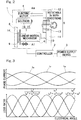
- Fig. 3 is a diagram showing the relationship between electrical angle phase and three phase currents and the relationship between electrical angle phase and loss, in one cycle of electrical angle in this electric brake device.
- the upper diagram shows three phase currents
- the lower diagram shows the proportion of copper loss of a predetermined phase to the entire copper loss, that is, loss ratio.
- the loss ratio indicates the easiness of heat generation of the exciting coil 4c of each phase.
- phase current of the u-phase exciting coil 4c is defined as i u
- phase current of the v-phase exciting coil 4c is defined as i v
- phase current of the w-phase exciting coil 4c is defined as i w
- the loss ratio of each phase at an electrical angle is expressed as follows.
- Fig. 4 is a diagram showing an example of deriving the range of electrical angle that should be adjusted in order to reduce loss in the exciting coils 4c in the electric brake device.
- Fig. 4 shows an example of deriving the range of an electrical angle ⁇ w of w-phase performed in step S9 or the like in Fig. 5 described later.
- the horizontal axis represents electrical angle
- the vertical axis represents loss ratio of each phase
- Fig. 4 is as same as diagram in Fig. 3 .
- the electrical angle at present is ⁇ e
- an updated electrical angle in order to reduce the loss of w-phase is ⁇ w .
- the loss ratio i w 2 ( ⁇ w ) at the electrical angle ⁇ w has to be smaller than the present loss ratio i w 2 ( ⁇ e ).
- the range that satisfies this Condition 1 is given as range (1) in Fig. 4 .
- the electrical angle of the electric motor 4 is adjusted, and a range in which the heat load assuredly becomes lower after the electrical angle adjustment than that before the electrical angle adjustment is searched for.
- the absolute value of an allowable error of a braking force that occurs as a result of setting or changing the electrical angle from ⁇ e to ⁇ w has to be not larger than a predetermined value. That is, the electrical angle ⁇ w has to be in a predetermined range having the present electrical angle ⁇ e substantially at the center thereof. In other words, the range in which the electrical angle of the electric motor 4 can be adjusted has to be within the range of the allowable error of the braking force.
- the allowable error setting section 24 is implemented by a hardware circuit or a software function on a processor (not shown) which can, upon reception of inputs such as vehicle speed information of the vehicle and by use of the above-described embodied model, set and output the allowable error (corresponding to variation electrical angle ⁇ ⁇ (described later) in the drawing) that allows follow-up control to be performed on the braking force with respect to the target braking force.
- a processor not shown
- the range that satisfies this Condition 2 is given as range (2) in Fig. 4 .
- the loss corresponding to the higher heat load is made to be smaller than the loss corresponding to the lower heat load. That is, it is sufficient that, between the corrected loss ratios i n 2 ( ⁇ w ), i v 2 ( ⁇ w ), a loss ratio relationship that is reverse to that between the present heat loads is realized.
- the range that satisfies this Condition 3 is given as range (3) in Fig. 4 .
- the range of the electrical angle ⁇ w that satisfies all the conditions above is given as the range shown in the lowest part of Fig. 4 .
- the electrical angle ⁇ w that minimizes the loss ratio i w 2 ( ⁇ w ) in this range is the angle at the position with " ⁇ w " which is indicated below the horizontal axis in Fig. 4 .
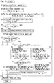
- Fig. 5 is a flow chart showing a temperature balancing process for the exciting coils 4c of this electric brake device.
- the control calculator 18 obtains a present electrical angle ⁇ e ( ⁇ ) ( ⁇ represents a discrete value on the time axis) (step S1), and obtains each phase current I( ⁇ ) (step S2).
- the exciting coil temperature balance corrector 19 calculates an estimated loss P( ⁇ ) for each phase (step S3). Specifically, in a case where a predetermined braking force is maintained, copper loss of an exciting coil 4c is proportional to the square of the current.
- the exciting coil temperature balance corrector 19 may estimate the loss of the exciting coil 4c, on the basis of an integrated value of the square of the current detected by the current sensor 21 or a value proportional to this square of the current.
- a predetermined value P s may be subtracted. The predetermined value P s is determined in advance on the basis of a result of a test, a simulation, or the like.
- the exciting coil temperature balance corrector 19 calculates a loss ratio R( ⁇ ) from the calculated estimated loss P( ⁇ ) of each phase (step S4).
- the estimated loss of the specific exciting coil 4c (for now, any one of u-phase, v-phase, and w-phase) is larger than a predetermined threshold r th (step S5: no)
- the energization phase adjustment section 23 performs later-described operation of reducing the heat load of the specific exciting coil 4c (step S14, or the like). If the estimated loss of the specific exciting coil 4c is not larger than the predetermined threshold (step S5: yes), ordinary or normal braking force control by the basic control section 22 is performed (step S15). Then, this process is ended.
- step S5 the difference or ratio among the estimated losses of the plurality of exciting coils may be used.
- the threshold is determined on the basis of a result of a test, a simulation, or the like.
- step S5 when the estimated loss of the specific exciting coil 4c is larger than the predetermined threshold (step S5: no), the allowable error setting section 24 obtains an allowable error F ⁇ for an allowable braking force relative to the present target braking force, and the energization phase adjustment section 23 obtains a variation electrical angle ⁇ ⁇ that satisfies the allowable error F ⁇ (step S6).
- the value of the allowable error F ⁇ is set to be variable such that: when the braking force is large and thus the electric motor 4 readily generates heat, the energization phase adjustment section 23 performs control of varying the braking force; and when the braking force is small and the electric motor 4 does not readily generate heat, the energization phase adjustment section 23 does not readily perform the control, it is preferable because unexpected braking force variation is less likely to occur.
- the exciting coil temperature balance corrector 19 determines the largest element (specific exciting coil 4c) that has the highest heat load among the u-phase, the v-phase, and the w-phase (step S7).
- the conditions to be satisfied are "Condition 1: copper loss at the updated electrical angle is reduced;
- step S8 to S10 in consideration of the relationship between the estimated losses of the exciting coils 4c (in this example, exciting coils 4c of u-phase and v-phase) other than the specific exciting coil, correction is performed so as to satisfy "Condition 3: the loss of the exciting coil 4c that has the higher estimated loss is lowered".
- the exciting coil temperature balance corrector 19 determines the phases that have the second highest heat load and the third highest heat load (step S8). It should be noted that with respect to each case where either of the exciting coils 4c, 4c, of the u-phase and the v-phase has the highest heat load, the operation is basically the same. Thus, the process corresponding to step S8 to step S14 for each exciting coil 4c, 4c of the u, v-phase is omitted in Fig. 5 .
- step S8: no the range of the electrical angle ⁇ w that satisfies all the above-described Conditions 1, 2, and 3 is determined (step S9, 10).
- step S11: no there are cases where, as a result of inclusion of Condition 3, all the conditions are not satisfied (step S11: no).
- the exciting coil temperature balance corrector 19 can determine an updated electrical angle on the basis of Conditions 1 and 2 (step S12). Then, the process is shifted to step S14.
- the exciting coil temperature balance corrector 19 determines the electrical angle ⁇ w that minimizes the loss ratio i w 2 ( ⁇ w ) (step S13). Then, the energization phase adjustment section 23 offsets the target braking force such that the electrical angle ⁇ w becomes the electrical angle ⁇ e (step S14), to control the braking force (step S15). Then, this process is ended.
- Fig. 6 is a diagram showing an operation example in which the control of this electric brake device is performed.
- the control calculator 18 is performing follow-up control on braking force F b with respect to target braking force F r .
- the breaking force F b is maintained to be constant at a large braking force at which the electric motor 4 readily generates heat
- the energization phase adjustment section 23 causes the braking force to be slightly varied for a time period t1 (t1 is several milliseconds to several tens of milliseconds, for example) within the above-described allowable error range.
- t1 is several milliseconds to several tens of milliseconds, for example
- the motor phase currents continuously applied at constant levels are changed, respectively.
- the heat generation amount of the specific exciting coil 4c is decreased, and the heat loads of the exciting coils 4c can be equalized.
- Fig. 7 is a diagram showing an operation example in which control of an electric brake device of a conventional example is performed.
- chart (a) of Fig. 7 although follow-up control is performed on the braking force F b with respect to the target braking force F r , since a predetermined braking force F b is maintained, the motor phase currents are continuously applied at constant levels as shown in chart (b) of Fig. 7 .
- chart (c) of Fig. 7 the heat generation amount of the specific exciting coil readily increases, i.e., the integrated value of the coil copper loss readily increases.
- the exciting coil temperature balance corrector 19 of the electric brake device DB estimates the balance degree of the heat generation amounts of the plurality of the exciting coils 4c.
- the exciting coil temperature balance corrector 19 has estimated that the heat generation amount of a specific exciting coil 4c is larger than the heat generation amounts of the other exciting coils 4c, the energization phase adjustment section 23 decreases the heat generation amount of the specific exciting coil 4c. Accordingly, durability against heat of the electric motor 4 can be improved.
- the rated torque can be improved or the output limit time of the maximum torque can be extended.
- the design requirement for copper loss relative to torque can be reduced, and the size and weight of the electric motor 4 can be reduced.
- the allowable error setting section 24 causes the allowable error to be varied such that the larger the target braking force or the braking force is, the larger the allowable error is.
- fine or detailed control can be realized such that: when the braking force is large and thus the electric motor 4 readily generates heat, the energization phase adjustment section 23 readily performs control of varying the braking force; and when the braking force is small and thus the electric motor 4 does not readily generate heat, the energization phase adjustment section 23 does not readily perform the control. Accordingly, unexpected braking force variation is less likely to occur. Then it is preferable because occupants of the vehicle are prevented from feeling that riding comfort is impaired.
- a vehicle speed information obtaining section 26 which obtains vehicle speed information of the vehicle having the electric brake device DB mounted thereto may be provided to the control calculator 18, for example.
- the vehicle speed information is inputted to the vehicle speed information obtaining section 26 through the higher-order ECU 17, for example.
- the allowable error setting section 24 may cause the allowable error to be varied such that the lower the vehicle speed obtained by the vehicle speed information obtaining section 26 is, the larger the allowable error becomes.
- fine or detailed control can be realized such that: for example, when the vehicle is travelling at a middle-to-low speed, the allowable error is made larger such that the energization phase adjustment section 23 readily performs control of varying the braking force; and when the vehicle is travelling at a high speed where highly accurate braking force control is required, the allowable error is made smaller such that the energization phase adjustment section 23 does not readily perform the control.
- a DC motor using a brush, a slip ring, and the like, or a stepping motor may be used, for example.
- the linear motion mechanism may be a mechanism such as a planetary roller screw, a ball ramp, or the like.
- a parallel gear, a worm gear, a planetary gear, or the like may be used.
- a belt or the like that is inexpensive may be used.
- sensor-less estimation may be used as necessary. In general, in a case where sensor-less estimation is used, the cost can be reduced but the accuracy is impaired, compared to those in a case where a sensor is used.
Landscapes
- Engineering & Computer Science (AREA)
- Mechanical Engineering (AREA)
- Transportation (AREA)
- Power Engineering (AREA)
- General Engineering & Computer Science (AREA)
- Physics & Mathematics (AREA)
- Fluid Mechanics (AREA)
- Braking Arrangements (AREA)
- Braking Systems And Boosters (AREA)
- Control Of Electric Motors In General (AREA)
- Regulating Braking Force (AREA)
- Connection Of Motors, Electrical Generators, Mechanical Devices, And The Like (AREA)
Abstract
Description
- This application is based on and claims Convention priority to Japanese patent application No.
2015-104293, filed May 22, 2015 - The present invention relates to an electrically powered brake device or electric brake device, and to a technology for improving durability of this electric brake device.
- As an electric brake device using an electric motor, the following technologies have been proposed.
- 1. An electric brake device that converts rotary motion of an electric motor to linear motion through a linear motion mechanism by pushing a brake pedal to press a brake pad against a brake disc and bring the brake pad into contact with the brake disc, thereby applying a braking force (Patent Document 1).
- 2. An electric brake device using a planetary roller screw mechanism (Patent Document 2).
- 3. A technology in which a thermistor is provided at a neutral point terminal of coils of respective phases in an electric motor, and the mean temperature of the respective phase coils is measured by the thermistor (Patent Document 3).
- 4. A technology of estimating a coil temperature on the basis of a temperature characteristic of voltage, current, and copper resistance when an electric motor is in a stopped state or stoppage state (Patent Document 4).
-
- [Patent Document 1]
JP Laid-open Patent Publication No. H6-327190 - [Patent Document 2]
JP Laid-open Patent Publication No. 2006-194356 - [Patent Document 3]
JP Laid-open Patent Publication No. H11-234964 - [Patent Document 4]
JP Laid-open Patent Publication No. 2004-208453 - In such an electric brake device as in
Patent Document - In order to avoid the above-described situation, temperature management of the motor coil is required. A technique of estimating the motor coil temperature by use of a temperature-dependent characteristic of the resistance value of copper, as shown in
Patent Document 4, for example, and a technique in which a thermo-sensitive device such as a thermistor is disposed at a motor coil, as shown inPatent Document 3, for example, are used in general. - However, for example, in a servomotor of a system such as an electric actuator used in an electric brake, current is concentrated on a specific coil among a plurality of coils, thus causing uneven heat generation, and therefore, accurate coil temperature cannot be obtained in some cases. Even if the accurate coil temperature is obtained, the above-described current concentration causes the heat load to be concentrated on only the specific coil, which could cause reduced durability against heat.
- An object of the present invention is to provide an electric brake device that can improve durability against heat of an electric motor of the electric brake device.
- Hereinafter, for convenience of easy understanding, description of the present invention will be given with reference to the reference characters used in embodiments.
- An electric brake device of the present invention includes:
- a
brake rotor 8; - a
friction member 9 configured to be brought into contact with thebrake rotor 8; - a
friction member operator 6 configured to bring thefriction member 9 into contact with thebrake rotor 8; - an
electric motor 4 configured to drive thefriction member operator 6; and - a
controller 2 configured to control a braking force by means of theelectric motor 4, wherein - the
controller 2 includes:- a heat
balance degree estimator 19 configured to estimate a balance degree among heat generation amounts of a plurality of exciting coils 4c in theelectric motor 4; and - a heat
load balancing section 23 configured to decrease a heat generation amount of a specific exciting coil 4c, when the heatbalance degree estimator 19 has estimated that the heat generation amount of the specific exciting coil 4c among the plurality of exciting coils 4c is larger than heat generation amounts of the other exciting coils 4c.
- a heat
- The exciting coils 4c are, for example, three-phase coils forming magnetic poles for causing rotation in the
electric motor 4. The balance degree among the heat generation amounts is the relative difference, caused by variation in losses of the exciting coils 4c, among the heat generation amounts that occur in the respective exciting coils 4c. - According to this configuration, in a case where the braking force is maintained to be constant, the motor phase currents are continuously applied always at constant levels. Thus, the losses of the respective exciting coils 4c vary, which results in a difference in the heat generation amounts of the respective exciting coils 4c. Thus, the heat
balance degree estimator 19 estimates the balance degree of the heat generation amounts of the plurality of exciting coils 4c. When the heatbalance degree estimator 19 has estimated that the heat generation amount of the specific exciting coil 4c is larger than the heat generation amounts of the other exciting coils 4c, the heatload balancing section 23 decreases the heat generation amount of the specific exciting coil 4c. Accordingly, durability against heat of theelectric motor 4 can be improved. Thus, with respect to theelectric motor 4, the rated torque can be improved or the output limit time of the maximum torque can be extended. In addition, the design requirement for copper loss relative to torque can be reduced, and the size and weight of theelectric motor 4 can be reduced. - A configuration may be employed in which the electric brake device includes a braking force estimator Sa configured to determine an estimated value of a braking force that occurs by the
friction member 9 being pressed against thebrake rotor 8, wherein
thecontroller 2 includes an allowableerror setting section 24 configured to set an allowable error that is to be used in follow-up control performed on the braking force with respect to a target braking force, and
the heatload balancing section 23 causes the braking force to be varied such that an energization phase is realized in which an absolute value of a current of the specific exciting coil 4c becomes smaller than an original value thereof within a range of the allowable error set by the allowableerror setting section 24. - In this case, the allowable
error setting section 24 sets a range (the range of the allowable error) which allows theelectric motor 4 to be operated irrespective of the target braking force. The heatload balancing section 23 decreases the heat generation amount of the specific exciting coil 4c by causing the braking force to be slightly varied so as to realize an energization phase in which the absolute value of the current of the specific exciting coil 4c becomes smaller than the original value thereof within the range of the allowable error. In this manner, by causing the braking force to be slightly varied relative to the target braking force within the allowable error range, it is possible to equalize the heat generation amounts (heat loads) of the respective exciting coils 4c. - The allowable
error setting section 24 may cause the allowable error to be varied such that the larger the target braking force or the braking force is, the larger the allowable error becomes. In this case, fine or detailed control can be realized such that: when the braking force is large and thus theelectric motor 4 readily generates heat, the heatload balancing section 23 readily performs control of varying the braking force; and when the braking force is small and thus theelectric motor 4 does not readily generate heat, the heatload balancing section 23 does not readily perform the control. This is preferable because unexpected braking force variation is less likely to occur. - A configuration may be employed in which the
controller 2 includes a vehicle speedinformation obtaining section 26 configured to obtain information of vehicle speed of a vehicle to which the electric brake device DB is mounted, and the allowableerror setting section 24 causes the allowable error to be varied such that the lower the vehicle speed obtained by the vehicle speedinformation obtaining section 26 is, the larger the allowable error becomes. In this case, fine or detailed control can be realized such that: for example, when the vehicle is traveling at a middle-to-low speed, the allowable error is made larger such that the heatload balancing section 23 readily performs control of varying the braking force; and when the vehicle is traveling at a high speed where highly accurate braking force control is required, the allowable error is made smaller such that the heatload balancing section 23 does not readily perform the control. - The heat
balance degree estimator 19 may estimate the balance degree among the heat generation amounts of the respective exciting coils 4c on the basis of an integrated value of a value proportional to a square of an estimated value of a current in each exciting coil 4c. In a case where a predetermined braking force is maintained, since copper loss of an exciting coil 4c is proportional to the square of the current, the heatbalance degree estimator 19 estimates the balance degree among the heat generation amounts of the respective exciting coils 4c on the basis of an integrated value of a value proportional to the square of an estimated value of a current in each exciting coil 4c. - A configuration may be employed in which when the heat
balance degree estimator 19 has determined that a value of either one of or both of: a difference between the integrated value in a determined exciting coil 4c and the integrated values of the other exciting coils 4c; and a ratio of the differences has exceeded a threshold, the heatload balancing section 23 decreases the heat generation amount of the specific exciting coil 4c. The threshold is determined on the basis of a result of a test or a simulation, for example. - Any combination of at least two constructions, disclosed in the appended claims and/or the specification and/or the accompanying drawings should be construed as included within the scope of the present invention. In particular, any combination of two or more of the appended claims should be equally construed as included within the scope of the present invention.
- In any event, the present invention will become more clearly understood from the following description of preferred embodiments thereof, when taken in conjunction with the accompanying drawings. However, the embodiments and the drawings are given only for the purpose of illustration and explanation, and are not to be taken as limiting the scope of the present invention in any way whatsoever, which scope is to be determined by the appended claims. In the accompanying drawings, like reference numerals are used to denote like parts throughout the several views, and:
-
Fig. 1 is a block diagram of a control system of an electric brake device according to an embodiment of the present invention; -
Fig. 2 is a schematic diagram showing an electric brake actuator of the electric brake device; -
Fig. 3 is a diagram showing the relationship between electrical angle phase and three phase currents and the relationship between electrical angle phase and loss, in one cycle of electrical angle in the electric brake device; -
Fig. 4 is a diagram showing an example of deriving the range of electrical angle that should be adjusted in order to reduce loss in the exciting coils in the electric brake device; -
Fig. 5 is a flow chart showing a temperature balancing process for the exciting coils of the electric brake device; -
Fig. 6 is a diagram showing an operation example in which control of the electric brake device is performed; and -
Fig. 7 is a diagram showing an operation example in which control of an electric brake device of a conventional example is performed. - An electric brake device according to an embodiment of the present invention is described with reference to
Fig. 1 to Fig. 6 . As shown inFig. 1 , an electric brake device DB includes anelectric brake actuator 1 and acontroller 2. The electric brake device DB is mounted on a vehicle. In this case, although not shown, the electric brake device DB is provided for each wheel, for example. Apower supply device 3 and a higher-order ECU 17 which is higher-order control unit for thecontroller 2 are connected to thecontroller 2. First, theelectric brake actuator 1 is described. - As shown in
Fig. 2 , theelectric brake actuator 1 includes: anelectric motor 4; aspeed reduction mechanism 5 which reduces a speed of rotation or number of rotation per unit time of theelectric motor 4; alinear motion mechanism 6 which is friction member operator; aparking brake mechanism 7 which is a parking brake; abrake rotor 8; and afriction member 9. Theelectric motor 4, thespeed reduction mechanism 5, and thelinear motion mechanism 6 are incorporated in, for example, a housing, which is not shown, or the like. Theelectric motor 4 is composed of a three-phase synchronous motor or the like. - The
speed reduction mechanism 5 reduces the speed of rotation of theelectric motor 4 and transmits the reduced rotation to arotation shaft 10 of thelinear motion mechanism 6. Thespeed reduction mechanism 5 includes aprimary gear 12, an intermediate (secondary)gear 13, and atertiary gear 11. In this example, thespeed reduction mechanism 5 is able to reduce, by theintermediate gear 13, the speed of rotation of theprimary gear 12 mounted to arotor shaft 4a of theelectric motor 4 and transmit the reduced rotation to thetertiary gear 11 fixed to an end portion of therotation shaft 10. - The
linear motion mechanism 6 which is the friction member operator converts rotary motion outputted from thespeed reduction mechanism 5 to linear motion of alinear motion portion 14 by a feed screw mechanism, and bring thefriction member 9 into contact with thebrake rotor 8 or separate thefriction member 9 from thebrake rotor 8. Thelinear motion portion 14 is supported in such a manner as to be prevented from rotating and as to be movable in an axial direction shown by an arrow A1 inFig. 2 . Thefriction member 9 is provided at an outboard-side end of thelinear motion portion 14. Rotation of theelectric motor 4 is transmitted to thelinear motion mechanism 6, through thespeed reduction mechanism 5, thereby converting the rotary motion to the linear motion, and the linear motion is converted to a pressing force of thefriction member 9, thereby generating the braking force which is an axial force of thelinear motion mechanism 6. It should be noted that, in a state where a plurality of the electric brake devices DB (Fig. 1 ) are mounted to a vehicle, the outer side of the vehicle is referred to as outboard side, and the center side of the vehicle is referred to as inboard side. - For example, a linear solenoid is used as an
actuator 16 of theparking brake mechanism 7. Theactuator 16 causes a lock member (solenoid pin) 15 to be advanced, to be fitted into and engaged with a locking hole (not shown) formed in theintermediate gear 13, thereby preventing rotation of theintermediate gear 13. Accordingly, a parking lock state is realized. When thelock member 15 is disengaged from the locking hole to allow rotation of theintermediate gear 13, an unlock state is realized. - The controller and the like shown in
Fig. 1 are described. As the higher-order ECU 17, an electric control unit that performs general control of the vehicle is used, for example. The higher-order ECU 17 has an integrated control function for the electric brake devices DB. From the higher-order ECU 17, for example, a target value (target braking force) of a braking force or the like is inputted to acontrol calculator 18 of thecontroller 2. It is sufficient that a target braking force is a value that corresponds to a braking force, and may be, for example, a value detected by a braking force sensor, or a motor angle that causes a desired braking force to be generated. - The
power supply device 3 supplies electric power to each of theelectric motor 4 and thecontroller 2 in each electric brake device DB. Thecontroller 2 includes: thecontrol calculator 18, an exciting coil temperature balance corrector (described later) 19 which is heat balance degree estimator; amotor driver 20, acurrent sensor 21, and the like. Thecontrol calculator 18 and the exciting coiltemperature balance corrector 19 may be each implemented, for example, by a processor such as a microcomputer, or a hardware module such as ASIC, FPGA, or DSP. The exciting coiltemperature balance corrector 19 can include a ROM (read only memory) having a program to be executed by the processor, and other electronic circuits such as a RAM (random access memory) and a co-processor, etc. - The
control calculator 18 includes: abasic control section 22; an energization phase adjustment section 23 (described later) which is a heat load balancing section; and an allowable error setting section 24 (described later). Thebasic control section 22 generates, on the basis of values obtained byvarious sensors 25, a control signal for amotor driver 20 so as to achieve the control target obtained from the higher-order ECU 17. Themotor driver 20 converts DC power from thepower supply device 3 to three-phase AC power to be used in driving theelectric motor 4. Themotor driver 20 may form a half-bridge circuit, a full-bridge circuit, or the like that uses a switching element such as MOSFET or IGBT, for example. Themotor driver 20 may include a predriver that instantaneously drives the switching element. - The
current sensor 21 is current detector which determines currents that are to be caused to flow in three-phase exciting coils 4c, respectively. Thecurrent sensor 21 is one of the above-mentionedvarious sensors 25. For example, thecurrent sensor 21 may be a current sensor of a type that detects magnetic field that is occurred around the power transmission route, or a current sensor of a type that detects a voltage drop amount by use of a shunt resistor and an operational amplifier, or alternatively, may perform estimation on the basis of a characteristic equation regarding current and voltage of theelectric motor 4. Further, when measurement of the three-phase current is performed, currents of only two phases of the three phases are measured, and the remaining one phase may be determined by use of a characteristic that the total sum of the currents of three phases is zero, for example. - As the
electric motor 4, a brushless DC motor is used, for example. The brushless DC motor is suitable for an electric servo system in which high speed, small size, and high accuracy are realized. In the case of the brushless DC motor, the exciting coil 4c of theelectric motor 4 may be in the form of concentrated winding in which winding is concentrated on one tooth, or may be in the form of distributed winding in which winding is made over a plurality of teeth. When the concentrated winding and the distributed winding are compared with each other, the concentrated winding allows downsizing, and thus, is suitable for an electric brake device for which the mounting space is limited, whereas the distributed winding can realize high efficiency and low torque ripple. - As the
various sensors 25, a braking force sensor Sa which is braking force estimator, a rotor angle sensor Sb, a temperature sensor Sc, or the like can be used. It is sufficient that the braking force sensor Sa can estimate an actually-occurring braking force, on the basis of the characteristic of theelectric brake actuator 1 and on the basis of a detection value obtained by sensing the influence that has been caused by operation of the electric brake device DB and that is occurring in the electric brake device DB itself or the wheel. Alternatively, the braking force sensor Sa may be a load sensor which detects the load of theelectric brake actuator 1, for example. - As the load sensor, a magnetic sensor is used, for example. As shown in
Fig. 2 , when thefriction member 9 presses thebrake rotor 8, a counterforce toward the inboard side acts on thelinear motion portion 14. The load sensor which is a magnetic sensor magnetically detects this counterforce of the braking force, as a displacement amount in the axial direction. If the relationship between the output from the sensor and the counterforce of the braking force is set in advance through a test or the like, the braking force estimator can estimate the braking force on the basis of an output from the load sensor. As the load sensor, an optical sensor, an eddy current-type sensor, or a capacitance-type sensor can be used instead of the magnetic sensor. - As the rotor angle sensor Sb shown in
Fig. 1 , for example, a sensor such as a resolver or a magnetic encoder may be mounted to theelectric motor 4, and the rotor angle may be obtained through so-called sensor-less estimation by use of coil voltage during rotation. In a case where a sensor such as a magnetic encoder is used, the rotor angle can be detected with high accuracy, and in a case where the rotor angle is obtained through sensor-less estimation, it is advantageous in terms of space saving and cost reduction. The temperature sensor Sc estimates the temperature of each exciting coil 4c, and as the temperature sensor Sc, a thermistor or the like is used, for example. - In this embodiment, in particular, the
controller 2 is provided with the exciting coiltemperature balance corrector 19, and further, thecontrol calculator 18 is provided with the energizationphase adjustment section 23 which is the heat load balancing section, and the allowableerror setting section 24. On the basis of values obtained from thecurrent sensor 21, etc., the exciting coiltemperature balance corrector 19 estimates the balance degree among the heat generation amounts of the plurality of exciting coils 4c (u, v, w phases in this example) in theelectric motor 4. If the exciting coiltemperature balance corrector 19 estimates that the heat generation amount of a specific exciting coil 4c among the plurality of exciting coils 4c is larger than the heat generation amounts of the other exciting coils 4c, 4c, through comparison with a predetermined threshold, for example, the exciting coiltemperature balance corrector 19 outputs a request signal to the energizationphase adjustment section 23 so as to shift the energization phase of theelectric motor 4. For example, specifically, the exciting coiltemperature balance corrector 19 is implemented by a hardware circuit or by a software function on a processor (not shown) which can, by use of: a LUT (look up table) realized by software or hardware; a predetermined conversion function stored in a software library or hardware, etc., equivalent thereto; and further, a predetermined comparison function or hardware equivalent thereto, etc., hereinafter referred to as "embodied model", calculate the heat generation amount of a specific exciting coil 4c and the heat generation amounts of the other exciting coils 4c, 4c upon reception of inputs such as values obtained from thecurrent sensor 21, estimate the above-described balance degree, and output the above-described request signal. - When the energization
phase adjustment section 23 receives the request signal, the energizationphase adjustment section 23 causes theelectric motor 4 to rotate within the range of allowable error set by the allowableerror setting section 24, to adjust the energization phase. For example, specifically, the energizationphase adjustment section 23 is implemented by a hardware circuit or by a software function on a processor (not shown) which can, upon reception of inputs such as the present electrical angle and the request signal and by use of the above-described embodied model, calculate the energization phase and output the calculated energization phase. -
Fig. 3 is a diagram showing the relationship between electrical angle phase and three phase currents and the relationship between electrical angle phase and loss, in one cycle of electrical angle in this electric brake device. Hereinafter, description is given also with reference toFig. 1 as appropriate. InFig. 3 , the upper diagram shows three phase currents, and the lower diagram shows the proportion of copper loss of a predetermined phase to the entire copper loss, that is, loss ratio. The loss ratio indicates the easiness of heat generation of the exciting coil 4c of each phase. When the phase current of the u-phase exciting coil 4c is defined as iu, the phase current of the v-phase exciting coil 4c is defined as iv, and the phase current of the w-phase exciting coil 4c is defined as iw, the loss ratio of each phase at an electrical angle is expressed as follows. - Loss ratio of u-phase: iu 2/(iu 2+iv/+iw 2)
- Loss ratio of v-phase: iv 2/(iu 2+iv 2+iw 2)
- Loss ratio of w-phase: iw 2/(iu 2+iv 2+iw 2)
-
Fig. 4 is a diagram showing an example of deriving the range of electrical angle that should be adjusted in order to reduce loss in the exciting coils 4c in the electric brake device.Fig. 4 shows an example of deriving the range of an electrical angle θw of w-phase performed in step S9 or the like inFig. 5 described later. InFig. 4 , the horizontal axis represents electrical angle, and the vertical axis represents loss ratio of each phase, andFig. 4 is as same as diagram inFig. 3 . In this deriving example, it is assumed that the electrical angle at present is θe, and that an updated electrical angle in order to reduce the loss of w-phase is θw. - The loss ratio iw 2(θw) at the electrical angle θw has to be smaller than the present loss ratio iw 2(θe). The range that satisfies this
Condition 1 is given as range (1) inFig. 4 . In order to smooth the heat load, the electrical angle of theelectric motor 4 is adjusted, and a range in which the heat load assuredly becomes lower after the electrical angle adjustment than that before the electrical angle adjustment is searched for. - The absolute value of an allowable error of a braking force that occurs as a result of setting or changing the electrical angle from θe to θw has to be not larger than a predetermined value. That is, the electrical angle θw has to be in a predetermined range having the present electrical angle θe substantially at the center thereof. In other words, the range in which the electrical angle of the
electric motor 4 can be adjusted has to be within the range of the allowable error of the braking force. For example, specifically, the allowableerror setting section 24 is implemented by a hardware circuit or a software function on a processor (not shown) which can, upon reception of inputs such as vehicle speed information of the vehicle and by use of the above-described embodied model, set and output the allowable error (corresponding to variation electrical angle θδ (described later) in the drawing) that allows follow-up control to be performed on the braking force with respect to the target braking force. The range that satisfies thisCondition 2 is given as range (2) inFig. 4 . - In order to balance the entire coil temperature, it would be appropriate that, in consideration of the states of the heat loads of the other u and v phases, the loss corresponding to the higher heat load is made to be smaller than the loss corresponding to the lower heat load. That is, it is sufficient that, between the corrected loss ratios in 2(θw), iv 2(θw), a loss ratio relationship that is reverse to that between the present heat loads is realized. The range that satisfies this
Condition 3 is given as range (3) inFig. 4 . - The range of the electrical angle θw that satisfies all the conditions above (
Condition 1 to Condition 3) is given as the range shown in the lowest part ofFig. 4 . The electrical angle θw that minimizes the loss ratio iw 2(θw) in this range is the angle at the position with "θw" which is indicated below the horizontal axis inFig. 4 . -
Fig. 5 is a flow chart showing a temperature balancing process for the exciting coils 4c of this electric brake device. After this process is started, thecontrol calculator 18 obtains a present electrical angle θe(κ) (κ represents a discrete value on the time axis) (step S1), and obtains each phase current I(κ) (step S2). Next, the exciting coiltemperature balance corrector 19 calculates an estimated loss P(κ) for each phase (step S3). Specifically, in a case where a predetermined braking force is maintained, copper loss of an exciting coil 4c is proportional to the square of the current. Thus, the exciting coiltemperature balance corrector 19 may estimate the loss of the exciting coil 4c, on the basis of an integrated value of the square of the current detected by thecurrent sensor 21 or a value proportional to this square of the current. When an estimated loss P(κ) of each phase is calculated, a predetermined value Ps may be subtracted. The predetermined value Ps is determined in advance on the basis of a result of a test, a simulation, or the like. - Next, the exciting coil
temperature balance corrector 19 calculates a loss ratio R(κ) from the calculated estimated loss P(κ) of each phase (step S4). Among the estimated losses above, the estimated loss of the specific exciting coil 4c (for now, any one of u-phase, v-phase, and w-phase) is larger than a predetermined threshold rth (step S5: no), the energizationphase adjustment section 23 performs later-described operation of reducing the heat load of the specific exciting coil 4c (step S14, or the like). If the estimated loss of the specific exciting coil 4c is not larger than the predetermined threshold (step S5: yes), ordinary or normal braking force control by thebasic control section 22 is performed (step S15). Then, this process is ended. In step S5, the difference or ratio among the estimated losses of the plurality of exciting coils may be used. The threshold is determined on the basis of a result of a test, a simulation, or the like. - As described above, when the estimated loss of the specific exciting coil 4c is larger than the predetermined threshold (step S5: no), the allowable
error setting section 24 obtains an allowable error Fδ for an allowable braking force relative to the present target braking force, and the energizationphase adjustment section 23 obtains a variation electrical angle θδ that satisfies the allowable error Fδ (step S6). At this time, if the value of the allowable error Fδ is set to be variable such that: when the braking force is large and thus theelectric motor 4 readily generates heat, the energizationphase adjustment section 23 performs control of varying the braking force; and when the braking force is small and theelectric motor 4 does not readily generate heat, the energizationphase adjustment section 23 does not readily perform the control, it is preferable because unexpected braking force variation is less likely to occur. - Then, the exciting coil
temperature balance corrector 19 determines the largest element (specific exciting coil 4c) that has the highest heat load among the u-phase, the v-phase, and the w-phase (step S7). As described above, when the target electrical angle is to be updated with respect to the present electrical angle, the conditions to be satisfied are "Condition 1: copper loss at the updated electrical angle is reduced; Condition 2: the updated target electrical angle is within a range which allows theelectric motor 4 to be operated irrespective of the command for the braking force (target braking force), that is, within a predetermined braking force allowable error range. In addition to these conditions, preferably, as in steps S8 to S10, in consideration of the relationship between the estimated losses of the exciting coils 4c (in this example, exciting coils 4c of u-phase and v-phase) other than the specific exciting coil, correction is performed so as to satisfy "Condition 3: the loss of the exciting coil 4c that has the higher estimated loss is lowered". - Specifically, in a case where the heat load of the exciting coil 4c of the w-phase is higher than the heat loads of the exciting coils 4c, 4c of the u-phase and the v-phase (this description is based on this case), the exciting coil
temperature balance corrector 19 determines the phases that have the second highest heat load and the third highest heat load (step S8). It should be noted that with respect to each case where either of the exciting coils 4c, 4c, of the u-phase and the v-phase has the highest heat load, the operation is basically the same. Thus, the process corresponding to step S8 to step S14 for each exciting coil 4c, 4c of the u, v-phase is omitted inFig. 5 . - Each of the cases where the phase having the second highest heat load is the u-phase (step S8: no), and where the phase having the second highest heat load is the v-phase (step S8: yes), the range of the electrical angle θw that satisfies all the above-described
Conditions Condition 3, all the conditions are not satisfied (step S11: no). In such a case, the exciting coiltemperature balance corrector 19 can determine an updated electrical angle on the basis ofConditions 1 and 2 (step S12). Then, the process is shifted to step S14. - If the electrical angle θw that satisfies all of
Conditions temperature balance corrector 19 determines the electrical angle θw that minimizes the loss ratio iw 2(θw) (step S13). Then, the energizationphase adjustment section 23 offsets the target braking force such that the electrical angle θw becomes the electrical angle θe (step S14), to control the braking force (step S15). Then, this process is ended. -
Fig. 6 is a diagram showing an operation example in which the control of this electric brake device is performed. As shown in chart (a) ofFig. 6 , thecontrol calculator 18 is performing follow-up control on braking force Fb with respect to target braking force Fr. When the breaking force Fb is maintained to be constant at a large braking force at which theelectric motor 4 readily generates heat, the energizationphase adjustment section 23 causes the braking force to be slightly varied for a time period t1 (t1 is several milliseconds to several tens of milliseconds, for example) within the above-described allowable error range. Accordingly, as shown in chart (b) ofFig. 6 , the motor phase currents continuously applied at constant levels are changed, respectively. As a result, as shown in chart (c) ofFig. 6 , the heat generation amount of the specific exciting coil 4c is decreased, and the heat loads of the exciting coils 4c can be equalized. - In contrast to this,
Fig. 7 is a diagram showing an operation example in which control of an electric brake device of a conventional example is performed. In this example, as shown in chart (a) ofFig. 7 , although follow-up control is performed on the braking force Fb with respect to the target braking force Fr, since a predetermined braking force Fb is maintained, the motor phase currents are continuously applied at constant levels as shown in chart (b) ofFig. 7 . As a result, as shown in chart (c) ofFig. 7 , the heat generation amount of the specific exciting coil readily increases, i.e., the integrated value of the coil copper loss readily increases. - According to the electric brake device described above, in a case where the braking force is maintained to be constant, the motor phase currents are continuously applied always at constant levels. Thus, the losses of the respective exciting coils vary, which results in a difference in the heat generation amounts of the respective exciting coils. Thus, the exciting coil
temperature balance corrector 19 of the electric brake device DB according to the present embodiment estimates the balance degree of the heat generation amounts of the plurality of the exciting coils 4c. When the exciting coiltemperature balance corrector 19 has estimated that the heat generation amount of a specific exciting coil 4c is larger than the heat generation amounts of the other exciting coils 4c, the energizationphase adjustment section 23 decreases the heat generation amount of the specific exciting coil 4c. Accordingly, durability against heat of theelectric motor 4 can be improved. Thus, with respect to theelectric motor 4, the rated torque can be improved or the output limit time of the maximum torque can be extended. In addition, the design requirement for copper loss relative to torque can be reduced, and the size and weight of theelectric motor 4 can be reduced. - The allowable
error setting section 24 causes the allowable error to be varied such that the larger the target braking force or the braking force is, the larger the allowable error is. In this case, fine or detailed control can be realized such that: when the braking force is large and thus theelectric motor 4 readily generates heat, the energizationphase adjustment section 23 readily performs control of varying the braking force; and when the braking force is small and thus theelectric motor 4 does not readily generate heat, the energizationphase adjustment section 23 does not readily perform the control. Accordingly, unexpected braking force variation is less likely to occur. Then it is preferable because occupants of the vehicle are prevented from feeling that riding comfort is impaired. - Another embodiment is described. As shown in
Fig. 1 , a vehicle speedinformation obtaining section 26 which obtains vehicle speed information of the vehicle having the electric brake device DB mounted thereto may be provided to thecontrol calculator 18, for example. The vehicle speed information is inputted to the vehicle speedinformation obtaining section 26 through the higher-order ECU 17, for example. In this case, the allowableerror setting section 24 may cause the allowable error to be varied such that the lower the vehicle speed obtained by the vehicle speedinformation obtaining section 26 is, the larger the allowable error becomes. In this case, fine or detailed control can be realized such that: for example, when the vehicle is travelling at a middle-to-low speed, the allowable error is made larger such that the energizationphase adjustment section 23 readily performs control of varying the braking force; and when the vehicle is travelling at a high speed where highly accurate braking force control is required, the allowable error is made smaller such that the energizationphase adjustment section 23 does not readily perform the control. - As the electric motor, a DC motor using a brush, a slip ring, and the like, or a stepping motor may be used, for example. The linear motion mechanism may be a mechanism such as a planetary roller screw, a ball ramp, or the like. As the speed reduction mechanism, a parallel gear, a worm gear, a planetary gear, or the like may be used. As for Functional aspect, a belt or the like that is inexpensive may be used. As each of the various sensors, sensor-less estimation may be used as necessary. In general, in a case where sensor-less estimation is used, the cost can be reduced but the accuracy is impaired, compared to those in a case where a sensor is used.
- Although the preferred modes for carrying out the present invention have been described on the basis of the embodiments with reference to the drawings, the embodiments disclosed herein are, in all aspects, illustrative and not restrictive. The scope of the present invention is indicated by claims, not by the above description. Those skilled in the art will readily conceive numerous changes and modifications within the framework of obviousness upon the reading of the specification herein presented of the present invention. Accordingly, such changes and modifications are to be construed as included in the scope of the invention defined by claims or in a scope equivalent thereto.
-
- 2 ···· controller
- 4 ···· electric motor
- 4c ···· exciting coil
- 6 ···· linear motion mechanism (friction member operator)
- 8 ···· brake rotor
- 9 ···· friction member
- 19 ···· exciting coil temperature balance corrector (heat balance degree estimator)
- 23 ···· energization phase adjustment section (heat load balancing section)
- 24 ···· allowable error setting section
- 26 ···· vehicle speed information obtaining section
- Sa ···· braking force sensor (braking force estimator)
Claims (6)
- An electric brake device comprising:a brake rotor;a friction member configured to be brought into contact with the brake rotor;a friction member operator configured to bring the friction member into contact with the brake rotor;an electric motor configured to drive the friction member operator; anda controller configured to control a braking force by means of the electric motor, whereinthe controller includes:a heat balance degree estimator configured to estimate a balance degree among heat generation amounts of a plurality of exciting coils in the electric motor; anda heat load balancing section configured to decrease a heat generation amount of a specific exciting coil, when the heat balance degree estimator has estimated that the heat generation amount of the specific exciting coil among the plurality of exciting coils is larger than heat generation amounts of the other exciting coils.
- The electric brake device as claimed in claim 1, comprising
a braking force estimator configured to determine an estimated value of a braking force that occurs by the friction member being pressed against the brake rotor, wherein
the controller includes allowable an error setting section configured to set an allowable error that is to be used in follow-up control performed on the braking force with respect to a target braking force, and
the heat load balancing section causes the braking force to be varied so as to realize an energization phase in which an absolute value of a current of the specific exciting coil becomes smaller than an original value thereof within a range of the allowable error set by the allowable error setting section. - The electric brake device as claimed in claim 2, wherein
the allowable error setting section causes the allowable error to be varied such that the larger the target braking force or the braking force is, the larger the allowable error becomes. - The electric brake device as claimed in claim 2 or 3, wherein
the controller includes a vehicle speed information obtaining section configured to obtain information of vehicle speed of a vehicle to which the electric brake device is mounted, and
the allowable error setting section causes the allowable error to be varied such that the lower the vehicle speed obtained by the vehicle speed information obtaining section is, the larger the allowable error becomes. - The electric brake device as claimed in any one of claims 1 to 4, wherein
the heat balance degree estimator estimates the balance degree among the heat generation amounts of the respective exciting coils on the basis of an integrated value of a value proportional to a square of an estimated value of a current in each exciting coil. - The electric brake device as claimed in claim 5, wherein
when the heat balance degree estimator has determined that a value of either one of or both of: a difference between the integrated value in a determined exciting coil and the integrated values of the other exciting coils; and a ratio of the differences has exceeded a threshold, the heat load balancing section decreases the heat generation amount of the specific exciting coil.
Applications Claiming Priority (2)
| Application Number | Priority Date | Filing Date | Title |
|---|---|---|---|
| JP2015104293A JP6570877B2 (en) | 2015-05-22 | 2015-05-22 | Electric brake device |
| PCT/JP2016/064872 WO2016190212A1 (en) | 2015-05-22 | 2016-05-19 | Electrically powered brake device |
Publications (3)
| Publication Number | Publication Date |
|---|---|
| EP3299231A1 true EP3299231A1 (en) | 2018-03-28 |
| EP3299231A4 EP3299231A4 (en) | 2019-01-09 |
| EP3299231B1 EP3299231B1 (en) | 2020-03-18 |
Family
ID=57393452
Family Applications (1)
| Application Number | Title | Priority Date | Filing Date |
|---|---|---|---|
| EP16799918.4A Active EP3299231B1 (en) | 2015-05-22 | 2016-05-19 | Electrically powered brake device |
Country Status (5)
| Country | Link |
|---|---|
| US (1) | US10479341B2 (en) |
| EP (1) | EP3299231B1 (en) |
| JP (1) | JP6570877B2 (en) |
| CN (1) | CN107614334B (en) |
| WO (1) | WO2016190212A1 (en) |
Families Citing this family (10)
| Publication number | Priority date | Publication date | Assignee | Title |
|---|---|---|---|---|
| CN110654356B (en) * | 2018-06-28 | 2021-09-21 | 比亚迪股份有限公司 | Control method and device for brake motor and vehicle |
| DE102018222500A1 (en) * | 2018-12-20 | 2020-06-25 | Robert Bosch Gmbh | Method for operating an electric synchronous motor |
| JP7242399B2 (en) | 2019-04-24 | 2023-03-20 | 日立Astemo株式会社 | Motor control device, electric brake device using the same, motor control method, and electric brake control method using this control method |
| FR3095792B1 (en) * | 2019-05-06 | 2021-04-16 | Safran Landing Systems | Method of controlling an electric braking system and an aircraft electric braking system |
| FR3100505B1 (en) * | 2019-09-11 | 2021-09-24 | Foundation Brakes France | ELECTRIC ACTUATOR OF A ROAD VEHICLE BRAKING SYSTEM |
| CN110823384B (en) * | 2020-01-09 | 2020-04-24 | 成都智创利源科技有限公司 | Switched reluctance motor detection system and control method |
| CN111969780B (en) * | 2020-07-14 | 2023-05-05 | 江苏大学 | A dynamometer emergency protection system and its implementation method |
| WO2023076942A1 (en) * | 2021-10-28 | 2023-05-04 | Atieva, Inc. | Rotor angle limit for static heating of electric motor |
| JP7552565B2 (en) * | 2021-12-08 | 2024-09-18 | 株式会社デンソー | Vehicle Brake Device |
| KR20240075002A (en) * | 2022-11-16 | 2024-05-29 | 현대자동차주식회사 | Minimization Device Of Motor Heat and Minimization Method Thereof |
Family Cites Families (13)
| Publication number | Priority date | Publication date | Assignee | Title |
|---|---|---|---|---|
| JP3166401B2 (en) | 1993-05-17 | 2001-05-14 | 日産自動車株式会社 | Electric brake actuator |
| JPH11234964A (en) | 1998-02-09 | 1999-08-27 | Asmo Co Ltd | Temperature detection structure for motor |
| JP3899489B2 (en) * | 2002-02-28 | 2007-03-28 | 株式会社日立製作所 | Electric disc brake device |
| JP2004208453A (en) | 2002-12-26 | 2004-07-22 | Nikon Corp | Motor coil temperature detection device, motor heat generation prevention device, motor drive device, stage device, exposure device, and semiconductor device manufacturing method |
| JP4422567B2 (en) * | 2004-06-30 | 2010-02-24 | 株式会社日立製作所 | Motor drive device, electric actuator, and electric power steering device |
| JP4898123B2 (en) | 2005-01-13 | 2012-03-14 | Ntn株式会社 | Electric linear actuator and electric brake device |
| JP4297109B2 (en) | 2005-12-09 | 2009-07-15 | トヨタ自動車株式会社 | Vehicle braking device |
| JP2007248982A (en) * | 2006-03-17 | 2007-09-27 | Ricoh Co Ltd | Image forming apparatus and toner |
| JP2008014323A (en) * | 2006-06-30 | 2008-01-24 | Hitachi Ltd | Electric brake device |
| JP2009220807A (en) * | 2008-02-22 | 2009-10-01 | Hitachi Ltd | Motor drive for car brake |
| JP2010119255A (en) * | 2008-11-14 | 2010-05-27 | Nikon Corp | Drive device of ac motor |
| US8994307B2 (en) * | 2009-01-16 | 2015-03-31 | International Business Machines Corporation | Selectively lowering resistance of a constantly used portion of motor windings in an electric motor |
| JP5884746B2 (en) * | 2013-02-08 | 2016-03-15 | 株式会社デンソー | AC motor control device |
-
2015
- 2015-05-22 JP JP2015104293A patent/JP6570877B2/en active Active
-
2016
- 2016-05-19 CN CN201680029166.3A patent/CN107614334B/en active Active
- 2016-05-19 EP EP16799918.4A patent/EP3299231B1/en active Active
- 2016-05-19 WO PCT/JP2016/064872 patent/WO2016190212A1/en not_active Ceased
-
2017
- 2017-11-20 US US15/817,595 patent/US10479341B2/en active Active
Also Published As
| Publication number | Publication date |
|---|---|
| EP3299231B1 (en) | 2020-03-18 |
| JP2016215887A (en) | 2016-12-22 |
| EP3299231A4 (en) | 2019-01-09 |
| CN107614334A (en) | 2018-01-19 |
| CN107614334B (en) | 2020-06-02 |
| WO2016190212A1 (en) | 2016-12-01 |
| US10479341B2 (en) | 2019-11-19 |
| US20180072295A1 (en) | 2018-03-15 |
| JP6570877B2 (en) | 2019-09-04 |
Similar Documents
| Publication | Publication Date | Title |
|---|---|---|
| US10479341B2 (en) | Electrically powered brake device | |
| US8791716B2 (en) | Anomaly detector of permanent magnet synchronous electric motor | |
| EP3863880B1 (en) | A traction control system | |
| US10654455B2 (en) | Electric brake device | |
| JP6664903B2 (en) | Electric brake device | |
| US10377355B2 (en) | Electric brake device | |
| US9428079B2 (en) | Electric vehicle | |
| JP6080894B2 (en) | Electric motor device and electric linear actuator | |
| US11441626B2 (en) | Electric linear actuator and electric brake device | |
| JP2018033228A (en) | Electric motor device | |
| JP5055836B2 (en) | Phase shift detection device and detection method for magnetic pole position sensor for synchronous motor | |
| JP5462121B2 (en) | Motor control device | |
| US20190217841A1 (en) | Electric brake device | |
| JP6502172B2 (en) | Electric brake device | |
| EP3402067B1 (en) | Motor drive device | |
| JP6765265B2 (en) | Electric brake device | |
| JP6629017B2 (en) | Electric motor device and electric linear actuator | |
| JP2020043665A (en) | Electric actuator and electric brake device | |
| JP2019137249A (en) | Electric brake device and electric brake system | |
| JP2019041503A (en) | Motor-driven direct-acting actuator and motor-driven brake device |
Legal Events
| Date | Code | Title | Description |
|---|---|---|---|
| STAA | Information on the status of an ep patent application or granted ep patent |
Free format text: STATUS: THE INTERNATIONAL PUBLICATION HAS BEEN MADE |
|
| PUAI | Public reference made under article 153(3) epc to a published international application that has entered the european phase |
Free format text: ORIGINAL CODE: 0009012 |
|
| STAA | Information on the status of an ep patent application or granted ep patent |
Free format text: STATUS: REQUEST FOR EXAMINATION WAS MADE |
|
| 17P | Request for examination filed |
Effective date: 20171205 |
|
| AK | Designated contracting states |
Kind code of ref document: A1 Designated state(s): AL AT BE BG CH CY CZ DE DK EE ES FI FR GB GR HR HU IE IS IT LI LT LU LV MC MK MT NL NO PL PT RO RS SE SI SK SM TR |
|
| AX | Request for extension of the european patent |
Extension state: BA ME |
|
| DAV | Request for validation of the european patent (deleted) | ||
| DAX | Request for extension of the european patent (deleted) | ||
| A4 | Supplementary search report drawn up and despatched |
Effective date: 20181207 |
|
| RIC1 | Information provided on ipc code assigned before grant |
Ipc: F16D 65/18 20060101ALI20181203BHEP Ipc: H02K 7/102 20060101ALI20181203BHEP Ipc: B60T 8/17 20060101AFI20181203BHEP Ipc: B60T 13/74 20060101ALI20181203BHEP Ipc: F16D 121/24 20120101ALI20181203BHEP Ipc: H02P 7/06 20060101ALI20181203BHEP |
|
| GRAP | Despatch of communication of intention to grant a patent |
Free format text: ORIGINAL CODE: EPIDOSNIGR1 |
|
| STAA | Information on the status of an ep patent application or granted ep patent |
Free format text: STATUS: GRANT OF PATENT IS INTENDED |
|
| INTG | Intention to grant announced |
Effective date: 20191122 |
|
| GRAS | Grant fee paid |
Free format text: ORIGINAL CODE: EPIDOSNIGR3 |
|
| GRAA | (expected) grant |
Free format text: ORIGINAL CODE: 0009210 |
|
| STAA | Information on the status of an ep patent application or granted ep patent |
Free format text: STATUS: THE PATENT HAS BEEN GRANTED |
|
| AK | Designated contracting states |
Kind code of ref document: B1 Designated state(s): AL AT BE BG CH CY CZ DE DK EE ES FI FR GB GR HR HU IE IS IT LI LT LU LV MC MK MT NL NO PL PT RO RS SE SI SK SM TR |
|
| REG | Reference to a national code |
Ref country code: GB Ref legal event code: FG4D |
|
| REG | Reference to a national code |
Ref country code: DE Ref legal event code: R096 Ref document number: 602016032172 Country of ref document: DE |
|
| REG | Reference to a national code |
Ref country code: AT Ref legal event code: REF Ref document number: 1245565 Country of ref document: AT Kind code of ref document: T Effective date: 20200415 Ref country code: IE Ref legal event code: FG4D |
|
| PG25 | Lapsed in a contracting state [announced via postgrant information from national office to epo] |
Ref country code: FI Free format text: LAPSE BECAUSE OF FAILURE TO SUBMIT A TRANSLATION OF THE DESCRIPTION OR TO PAY THE FEE WITHIN THE PRESCRIBED TIME-LIMIT Effective date: 20200318 Ref country code: RS Free format text: LAPSE BECAUSE OF FAILURE TO SUBMIT A TRANSLATION OF THE DESCRIPTION OR TO PAY THE FEE WITHIN THE PRESCRIBED TIME-LIMIT Effective date: 20200318 Ref country code: NO Free format text: LAPSE BECAUSE OF FAILURE TO SUBMIT A TRANSLATION OF THE DESCRIPTION OR TO PAY THE FEE WITHIN THE PRESCRIBED TIME-LIMIT Effective date: 20200618 |
|
| REG | Reference to a national code |
Ref country code: NL Ref legal event code: MP Effective date: 20200318 |
|
| PG25 | Lapsed in a contracting state [announced via postgrant information from national office to epo] |
Ref country code: GR Free format text: LAPSE BECAUSE OF FAILURE TO SUBMIT A TRANSLATION OF THE DESCRIPTION OR TO PAY THE FEE WITHIN THE PRESCRIBED TIME-LIMIT Effective date: 20200619 Ref country code: BG Free format text: LAPSE BECAUSE OF FAILURE TO SUBMIT A TRANSLATION OF THE DESCRIPTION OR TO PAY THE FEE WITHIN THE PRESCRIBED TIME-LIMIT Effective date: 20200618 Ref country code: HR Free format text: LAPSE BECAUSE OF FAILURE TO SUBMIT A TRANSLATION OF THE DESCRIPTION OR TO PAY THE FEE WITHIN THE PRESCRIBED TIME-LIMIT Effective date: 20200318 Ref country code: LV Free format text: LAPSE BECAUSE OF FAILURE TO SUBMIT A TRANSLATION OF THE DESCRIPTION OR TO PAY THE FEE WITHIN THE PRESCRIBED TIME-LIMIT Effective date: 20200318 Ref country code: SE Free format text: LAPSE BECAUSE OF FAILURE TO SUBMIT A TRANSLATION OF THE DESCRIPTION OR TO PAY THE FEE WITHIN THE PRESCRIBED TIME-LIMIT Effective date: 20200318 |
|
| REG | Reference to a national code |
Ref country code: LT Ref legal event code: MG4D |
|
| PG25 | Lapsed in a contracting state [announced via postgrant information from national office to epo] |
Ref country code: NL Free format text: LAPSE BECAUSE OF FAILURE TO SUBMIT A TRANSLATION OF THE DESCRIPTION OR TO PAY THE FEE WITHIN THE PRESCRIBED TIME-LIMIT Effective date: 20200318 |
|
| PG25 | Lapsed in a contracting state [announced via postgrant information from national office to epo] |
Ref country code: CZ Free format text: LAPSE BECAUSE OF FAILURE TO SUBMIT A TRANSLATION OF THE DESCRIPTION OR TO PAY THE FEE WITHIN THE PRESCRIBED TIME-LIMIT Effective date: 20200318 Ref country code: IS Free format text: LAPSE BECAUSE OF FAILURE TO SUBMIT A TRANSLATION OF THE DESCRIPTION OR TO PAY THE FEE WITHIN THE PRESCRIBED TIME-LIMIT Effective date: 20200718 Ref country code: RO Free format text: LAPSE BECAUSE OF FAILURE TO SUBMIT A TRANSLATION OF THE DESCRIPTION OR TO PAY THE FEE WITHIN THE PRESCRIBED TIME-LIMIT Effective date: 20200318 Ref country code: SM Free format text: LAPSE BECAUSE OF FAILURE TO SUBMIT A TRANSLATION OF THE DESCRIPTION OR TO PAY THE FEE WITHIN THE PRESCRIBED TIME-LIMIT Effective date: 20200318 Ref country code: EE Free format text: LAPSE BECAUSE OF FAILURE TO SUBMIT A TRANSLATION OF THE DESCRIPTION OR TO PAY THE FEE WITHIN THE PRESCRIBED TIME-LIMIT Effective date: 20200318 Ref country code: LT Free format text: LAPSE BECAUSE OF FAILURE TO SUBMIT A TRANSLATION OF THE DESCRIPTION OR TO PAY THE FEE WITHIN THE PRESCRIBED TIME-LIMIT Effective date: 20200318 Ref country code: SK Free format text: LAPSE BECAUSE OF FAILURE TO SUBMIT A TRANSLATION OF THE DESCRIPTION OR TO PAY THE FEE WITHIN THE PRESCRIBED TIME-LIMIT Effective date: 20200318 Ref country code: PT Free format text: LAPSE BECAUSE OF FAILURE TO SUBMIT A TRANSLATION OF THE DESCRIPTION OR TO PAY THE FEE WITHIN THE PRESCRIBED TIME-LIMIT Effective date: 20200812 |
|
| REG | Reference to a national code |
Ref country code: AT Ref legal event code: MK05 Ref document number: 1245565 Country of ref document: AT Kind code of ref document: T Effective date: 20200318 |
|
| REG | Reference to a national code |
Ref country code: DE Ref legal event code: R097 Ref document number: 602016032172 Country of ref document: DE |
|
| PLBE | No opposition filed within time limit |
Free format text: ORIGINAL CODE: 0009261 |
|
| STAA | Information on the status of an ep patent application or granted ep patent |
Free format text: STATUS: NO OPPOSITION FILED WITHIN TIME LIMIT |
|
| PG25 | Lapsed in a contracting state [announced via postgrant information from national office to epo] |
Ref country code: LI Free format text: LAPSE BECAUSE OF NON-PAYMENT OF DUE FEES Effective date: 20200531 Ref country code: MC Free format text: LAPSE BECAUSE OF FAILURE TO SUBMIT A TRANSLATION OF THE DESCRIPTION OR TO PAY THE FEE WITHIN THE PRESCRIBED TIME-LIMIT Effective date: 20200318 Ref country code: ES Free format text: LAPSE BECAUSE OF FAILURE TO SUBMIT A TRANSLATION OF THE DESCRIPTION OR TO PAY THE FEE WITHIN THE PRESCRIBED TIME-LIMIT Effective date: 20200318 Ref country code: IT Free format text: LAPSE BECAUSE OF FAILURE TO SUBMIT A TRANSLATION OF THE DESCRIPTION OR TO PAY THE FEE WITHIN THE PRESCRIBED TIME-LIMIT Effective date: 20200318 Ref country code: CH Free format text: LAPSE BECAUSE OF NON-PAYMENT OF DUE FEES Effective date: 20200531 Ref country code: DK Free format text: LAPSE BECAUSE OF FAILURE TO SUBMIT A TRANSLATION OF THE DESCRIPTION OR TO PAY THE FEE WITHIN THE PRESCRIBED TIME-LIMIT Effective date: 20200318 Ref country code: AT Free format text: LAPSE BECAUSE OF FAILURE TO SUBMIT A TRANSLATION OF THE DESCRIPTION OR TO PAY THE FEE WITHIN THE PRESCRIBED TIME-LIMIT Effective date: 20200318 |
|
| 26N | No opposition filed |
Effective date: 20201221 |
|
| PG25 | Lapsed in a contracting state [announced via postgrant information from national office to epo] |
Ref country code: PL Free format text: LAPSE BECAUSE OF FAILURE TO SUBMIT A TRANSLATION OF THE DESCRIPTION OR TO PAY THE FEE WITHIN THE PRESCRIBED TIME-LIMIT Effective date: 20200318 |
|
| REG | Reference to a national code |
Ref country code: BE Ref legal event code: MM Effective date: 20200531 |
|
| GBPC | Gb: european patent ceased through non-payment of renewal fee |
Effective date: 20200618 |
|
| PG25 | Lapsed in a contracting state [announced via postgrant information from national office to epo] |
Ref country code: LU Free format text: LAPSE BECAUSE OF NON-PAYMENT OF DUE FEES Effective date: 20200519 |
|
| PG25 | Lapsed in a contracting state [announced via postgrant information from national office to epo] |
Ref country code: IE Free format text: LAPSE BECAUSE OF NON-PAYMENT OF DUE FEES Effective date: 20200519 Ref country code: GB Free format text: LAPSE BECAUSE OF NON-PAYMENT OF DUE FEES Effective date: 20200618 |
|
| PG25 | Lapsed in a contracting state [announced via postgrant information from national office to epo] |
Ref country code: BE Free format text: LAPSE BECAUSE OF NON-PAYMENT OF DUE FEES Effective date: 20200531 Ref country code: SI Free format text: LAPSE BECAUSE OF FAILURE TO SUBMIT A TRANSLATION OF THE DESCRIPTION OR TO PAY THE FEE WITHIN THE PRESCRIBED TIME-LIMIT Effective date: 20200318 |
|
| PGFP | Annual fee paid to national office [announced via postgrant information from national office to epo] |
Ref country code: DE Payment date: 20210420 Year of fee payment: 6 Ref country code: FR Payment date: 20210426 Year of fee payment: 6 |
|
| PG25 | Lapsed in a contracting state [announced via postgrant information from national office to epo] |
Ref country code: TR Free format text: LAPSE BECAUSE OF FAILURE TO SUBMIT A TRANSLATION OF THE DESCRIPTION OR TO PAY THE FEE WITHIN THE PRESCRIBED TIME-LIMIT Effective date: 20200318 Ref country code: MT Free format text: LAPSE BECAUSE OF FAILURE TO SUBMIT A TRANSLATION OF THE DESCRIPTION OR TO PAY THE FEE WITHIN THE PRESCRIBED TIME-LIMIT Effective date: 20200318 Ref country code: CY Free format text: LAPSE BECAUSE OF FAILURE TO SUBMIT A TRANSLATION OF THE DESCRIPTION OR TO PAY THE FEE WITHIN THE PRESCRIBED TIME-LIMIT Effective date: 20200318 |
|
| PG25 | Lapsed in a contracting state [announced via postgrant information from national office to epo] |
Ref country code: MK Free format text: LAPSE BECAUSE OF FAILURE TO SUBMIT A TRANSLATION OF THE DESCRIPTION OR TO PAY THE FEE WITHIN THE PRESCRIBED TIME-LIMIT Effective date: 20200318 Ref country code: AL Free format text: LAPSE BECAUSE OF FAILURE TO SUBMIT A TRANSLATION OF THE DESCRIPTION OR TO PAY THE FEE WITHIN THE PRESCRIBED TIME-LIMIT Effective date: 20200318 |
|
| REG | Reference to a national code |
Ref country code: DE Ref legal event code: R119 Ref document number: 602016032172 Country of ref document: DE |
|
| PG25 | Lapsed in a contracting state [announced via postgrant information from national office to epo] |
Ref country code: FR Free format text: LAPSE BECAUSE OF NON-PAYMENT OF DUE FEES Effective date: 20220531 |
|
| PG25 | Lapsed in a contracting state [announced via postgrant information from national office to epo] |
Ref country code: DE Free format text: LAPSE BECAUSE OF NON-PAYMENT OF DUE FEES Effective date: 20221201 |