EP3299114A1 - Braze gel, brazing process, and brazing article - Google Patents
Braze gel, brazing process, and brazing article Download PDFInfo
- Publication number
- EP3299114A1 EP3299114A1 EP17192116.6A EP17192116A EP3299114A1 EP 3299114 A1 EP3299114 A1 EP 3299114A1 EP 17192116 A EP17192116 A EP 17192116A EP 3299114 A1 EP3299114 A1 EP 3299114A1
- Authority
- EP
- European Patent Office
- Prior art keywords
- braze
- gel
- component
- brazing
- coating
- Prior art date
- Legal status (The legal status is an assumption and is not a legal conclusion. Google has not performed a legal analysis and makes no representation as to the accuracy of the status listed.)
- Granted
Links
Images


Classifications
-
- F—MECHANICAL ENGINEERING; LIGHTING; HEATING; WEAPONS; BLASTING
- F01—MACHINES OR ENGINES IN GENERAL; ENGINE PLANTS IN GENERAL; STEAM ENGINES
- F01D—NON-POSITIVE DISPLACEMENT MACHINES OR ENGINES, e.g. STEAM TURBINES
- F01D11/00—Preventing or minimising internal leakage of working-fluid, e.g. between stages
- F01D11/02—Preventing or minimising internal leakage of working-fluid, e.g. between stages by non-contact sealings, e.g. of labyrinth type
-
- B—PERFORMING OPERATIONS; TRANSPORTING
- B23—MACHINE TOOLS; METAL-WORKING NOT OTHERWISE PROVIDED FOR
- B23K—SOLDERING OR UNSOLDERING; WELDING; CLADDING OR PLATING BY SOLDERING OR WELDING; CUTTING BY APPLYING HEAT LOCALLY, e.g. FLAME CUTTING; WORKING BY LASER BEAM
- B23K1/00—Soldering, e.g. brazing, or unsoldering
- B23K1/0008—Soldering, e.g. brazing, or unsoldering specially adapted for particular articles or work
- B23K1/0014—Brazing of honeycomb sandwich structures
-
- B—PERFORMING OPERATIONS; TRANSPORTING
- B23—MACHINE TOOLS; METAL-WORKING NOT OTHERWISE PROVIDED FOR
- B23K—SOLDERING OR UNSOLDERING; WELDING; CLADDING OR PLATING BY SOLDERING OR WELDING; CUTTING BY APPLYING HEAT LOCALLY, e.g. FLAME CUTTING; WORKING BY LASER BEAM
- B23K1/00—Soldering, e.g. brazing, or unsoldering
- B23K1/0008—Soldering, e.g. brazing, or unsoldering specially adapted for particular articles or work
- B23K1/0018—Brazing of turbine parts
-
- B—PERFORMING OPERATIONS; TRANSPORTING
- B23—MACHINE TOOLS; METAL-WORKING NOT OTHERWISE PROVIDED FOR
- B23K—SOLDERING OR UNSOLDERING; WELDING; CLADDING OR PLATING BY SOLDERING OR WELDING; CUTTING BY APPLYING HEAT LOCALLY, e.g. FLAME CUTTING; WORKING BY LASER BEAM
- B23K35/00—Rods, electrodes, materials, or media, for use in soldering, welding, or cutting
- B23K35/02—Rods, electrodes, materials, or media, for use in soldering, welding, or cutting characterised by mechanical features, e.g. shape
- B23K35/0222—Rods, electrodes, materials, or media, for use in soldering, welding, or cutting characterised by mechanical features, e.g. shape for use in soldering or brazing
-
- B—PERFORMING OPERATIONS; TRANSPORTING
- B23—MACHINE TOOLS; METAL-WORKING NOT OTHERWISE PROVIDED FOR
- B23K—SOLDERING OR UNSOLDERING; WELDING; CLADDING OR PLATING BY SOLDERING OR WELDING; CUTTING BY APPLYING HEAT LOCALLY, e.g. FLAME CUTTING; WORKING BY LASER BEAM
- B23K35/00—Rods, electrodes, materials, or media, for use in soldering, welding, or cutting
- B23K35/02—Rods, electrodes, materials, or media, for use in soldering, welding, or cutting characterised by mechanical features, e.g. shape
- B23K35/0222—Rods, electrodes, materials, or media, for use in soldering, welding, or cutting characterised by mechanical features, e.g. shape for use in soldering or brazing
- B23K35/0244—Powders, particles or spheres; Preforms made therefrom
-
- B—PERFORMING OPERATIONS; TRANSPORTING
- B23—MACHINE TOOLS; METAL-WORKING NOT OTHERWISE PROVIDED FOR
- B23K—SOLDERING OR UNSOLDERING; WELDING; CLADDING OR PLATING BY SOLDERING OR WELDING; CUTTING BY APPLYING HEAT LOCALLY, e.g. FLAME CUTTING; WORKING BY LASER BEAM
- B23K35/00—Rods, electrodes, materials, or media, for use in soldering, welding, or cutting
- B23K35/02—Rods, electrodes, materials, or media, for use in soldering, welding, or cutting characterised by mechanical features, e.g. shape
- B23K35/0222—Rods, electrodes, materials, or media, for use in soldering, welding, or cutting characterised by mechanical features, e.g. shape for use in soldering or brazing
- B23K35/0244—Powders, particles or spheres; Preforms made therefrom
- B23K35/025—Pastes, creams or slurries
-
- B—PERFORMING OPERATIONS; TRANSPORTING
- B23—MACHINE TOOLS; METAL-WORKING NOT OTHERWISE PROVIDED FOR
- B23K—SOLDERING OR UNSOLDERING; WELDING; CLADDING OR PLATING BY SOLDERING OR WELDING; CUTTING BY APPLYING HEAT LOCALLY, e.g. FLAME CUTTING; WORKING BY LASER BEAM
- B23K35/00—Rods, electrodes, materials, or media, for use in soldering, welding, or cutting
- B23K35/22—Rods, electrodes, materials, or media, for use in soldering, welding, or cutting characterised by the composition or nature of the material
- B23K35/24—Selection of soldering or welding materials proper
- B23K35/28—Selection of soldering or welding materials proper with the principal constituent melting at less than 950°C
- B23K35/286—Al as the principal constituent
-
- B—PERFORMING OPERATIONS; TRANSPORTING
- B23—MACHINE TOOLS; METAL-WORKING NOT OTHERWISE PROVIDED FOR
- B23K—SOLDERING OR UNSOLDERING; WELDING; CLADDING OR PLATING BY SOLDERING OR WELDING; CUTTING BY APPLYING HEAT LOCALLY, e.g. FLAME CUTTING; WORKING BY LASER BEAM
- B23K35/00—Rods, electrodes, materials, or media, for use in soldering, welding, or cutting
- B23K35/22—Rods, electrodes, materials, or media, for use in soldering, welding, or cutting characterised by the composition or nature of the material
- B23K35/24—Selection of soldering or welding materials proper
- B23K35/30—Selection of soldering or welding materials proper with the principal constituent melting at less than 1550°C
- B23K35/3006—Ag as the principal constituent
-
- B—PERFORMING OPERATIONS; TRANSPORTING
- B23—MACHINE TOOLS; METAL-WORKING NOT OTHERWISE PROVIDED FOR
- B23K—SOLDERING OR UNSOLDERING; WELDING; CLADDING OR PLATING BY SOLDERING OR WELDING; CUTTING BY APPLYING HEAT LOCALLY, e.g. FLAME CUTTING; WORKING BY LASER BEAM
- B23K35/00—Rods, electrodes, materials, or media, for use in soldering, welding, or cutting
- B23K35/22—Rods, electrodes, materials, or media, for use in soldering, welding, or cutting characterised by the composition or nature of the material
- B23K35/24—Selection of soldering or welding materials proper
- B23K35/30—Selection of soldering or welding materials proper with the principal constituent melting at less than 1550°C
- B23K35/3013—Au as the principal constituent
-
- B—PERFORMING OPERATIONS; TRANSPORTING
- B23—MACHINE TOOLS; METAL-WORKING NOT OTHERWISE PROVIDED FOR
- B23K—SOLDERING OR UNSOLDERING; WELDING; CLADDING OR PLATING BY SOLDERING OR WELDING; CUTTING BY APPLYING HEAT LOCALLY, e.g. FLAME CUTTING; WORKING BY LASER BEAM
- B23K35/00—Rods, electrodes, materials, or media, for use in soldering, welding, or cutting
- B23K35/22—Rods, electrodes, materials, or media, for use in soldering, welding, or cutting characterised by the composition or nature of the material
- B23K35/24—Selection of soldering or welding materials proper
- B23K35/30—Selection of soldering or welding materials proper with the principal constituent melting at less than 1550°C
- B23K35/302—Cu as the principal constituent
-
- B—PERFORMING OPERATIONS; TRANSPORTING
- B23—MACHINE TOOLS; METAL-WORKING NOT OTHERWISE PROVIDED FOR
- B23K—SOLDERING OR UNSOLDERING; WELDING; CLADDING OR PLATING BY SOLDERING OR WELDING; CUTTING BY APPLYING HEAT LOCALLY, e.g. FLAME CUTTING; WORKING BY LASER BEAM
- B23K35/00—Rods, electrodes, materials, or media, for use in soldering, welding, or cutting
- B23K35/22—Rods, electrodes, materials, or media, for use in soldering, welding, or cutting characterised by the composition or nature of the material
- B23K35/24—Selection of soldering or welding materials proper
- B23K35/30—Selection of soldering or welding materials proper with the principal constituent melting at less than 1550°C
- B23K35/3033—Ni as the principal constituent
-
- B—PERFORMING OPERATIONS; TRANSPORTING
- B23—MACHINE TOOLS; METAL-WORKING NOT OTHERWISE PROVIDED FOR
- B23K—SOLDERING OR UNSOLDERING; WELDING; CLADDING OR PLATING BY SOLDERING OR WELDING; CUTTING BY APPLYING HEAT LOCALLY, e.g. FLAME CUTTING; WORKING BY LASER BEAM
- B23K35/00—Rods, electrodes, materials, or media, for use in soldering, welding, or cutting
- B23K35/22—Rods, electrodes, materials, or media, for use in soldering, welding, or cutting characterised by the composition or nature of the material
- B23K35/24—Selection of soldering or welding materials proper
- B23K35/30—Selection of soldering or welding materials proper with the principal constituent melting at less than 1550°C
- B23K35/3046—Co as the principal constituent
-
- B—PERFORMING OPERATIONS; TRANSPORTING
- B23—MACHINE TOOLS; METAL-WORKING NOT OTHERWISE PROVIDED FOR
- B23K—SOLDERING OR UNSOLDERING; WELDING; CLADDING OR PLATING BY SOLDERING OR WELDING; CUTTING BY APPLYING HEAT LOCALLY, e.g. FLAME CUTTING; WORKING BY LASER BEAM
- B23K35/00—Rods, electrodes, materials, or media, for use in soldering, welding, or cutting
- B23K35/22—Rods, electrodes, materials, or media, for use in soldering, welding, or cutting characterised by the composition or nature of the material
- B23K35/36—Selection of non-metallic compositions, e.g. coatings or fluxes; Selection of soldering or welding materials, conjoint with selection of non-metallic compositions, both selections being of interest
-
- B—PERFORMING OPERATIONS; TRANSPORTING
- B23—MACHINE TOOLS; METAL-WORKING NOT OTHERWISE PROVIDED FOR
- B23K—SOLDERING OR UNSOLDERING; WELDING; CLADDING OR PLATING BY SOLDERING OR WELDING; CUTTING BY APPLYING HEAT LOCALLY, e.g. FLAME CUTTING; WORKING BY LASER BEAM
- B23K35/00—Rods, electrodes, materials, or media, for use in soldering, welding, or cutting
- B23K35/22—Rods, electrodes, materials, or media, for use in soldering, welding, or cutting characterised by the composition or nature of the material
- B23K35/36—Selection of non-metallic compositions, e.g. coatings or fluxes; Selection of soldering or welding materials, conjoint with selection of non-metallic compositions, both selections being of interest
- B23K35/3601—Selection of non-metallic compositions, e.g. coatings or fluxes; Selection of soldering or welding materials, conjoint with selection of non-metallic compositions, both selections being of interest with inorganic compounds as principal constituents
- B23K35/3603—Halide salts
-
- B—PERFORMING OPERATIONS; TRANSPORTING
- B23—MACHINE TOOLS; METAL-WORKING NOT OTHERWISE PROVIDED FOR
- B23K—SOLDERING OR UNSOLDERING; WELDING; CLADDING OR PLATING BY SOLDERING OR WELDING; CUTTING BY APPLYING HEAT LOCALLY, e.g. FLAME CUTTING; WORKING BY LASER BEAM
- B23K35/00—Rods, electrodes, materials, or media, for use in soldering, welding, or cutting
- B23K35/22—Rods, electrodes, materials, or media, for use in soldering, welding, or cutting characterised by the composition or nature of the material
- B23K35/36—Selection of non-metallic compositions, e.g. coatings or fluxes; Selection of soldering or welding materials, conjoint with selection of non-metallic compositions, both selections being of interest
- B23K35/3601—Selection of non-metallic compositions, e.g. coatings or fluxes; Selection of soldering or welding materials, conjoint with selection of non-metallic compositions, both selections being of interest with inorganic compounds as principal constituents
- B23K35/3603—Halide salts
- B23K35/3605—Fluorides
-
- B—PERFORMING OPERATIONS; TRANSPORTING
- B23—MACHINE TOOLS; METAL-WORKING NOT OTHERWISE PROVIDED FOR
- B23K—SOLDERING OR UNSOLDERING; WELDING; CLADDING OR PLATING BY SOLDERING OR WELDING; CUTTING BY APPLYING HEAT LOCALLY, e.g. FLAME CUTTING; WORKING BY LASER BEAM
- B23K35/00—Rods, electrodes, materials, or media, for use in soldering, welding, or cutting
- B23K35/22—Rods, electrodes, materials, or media, for use in soldering, welding, or cutting characterised by the composition or nature of the material
- B23K35/36—Selection of non-metallic compositions, e.g. coatings or fluxes; Selection of soldering or welding materials, conjoint with selection of non-metallic compositions, both selections being of interest
- B23K35/3612—Selection of non-metallic compositions, e.g. coatings or fluxes; Selection of soldering or welding materials, conjoint with selection of non-metallic compositions, both selections being of interest with organic compounds as principal constituents
- B23K35/3613—Polymers, e.g. resins
-
- B—PERFORMING OPERATIONS; TRANSPORTING
- B23—MACHINE TOOLS; METAL-WORKING NOT OTHERWISE PROVIDED FOR
- B23K—SOLDERING OR UNSOLDERING; WELDING; CLADDING OR PLATING BY SOLDERING OR WELDING; CUTTING BY APPLYING HEAT LOCALLY, e.g. FLAME CUTTING; WORKING BY LASER BEAM
- B23K35/00—Rods, electrodes, materials, or media, for use in soldering, welding, or cutting
- B23K35/22—Rods, electrodes, materials, or media, for use in soldering, welding, or cutting characterised by the composition or nature of the material
- B23K35/36—Selection of non-metallic compositions, e.g. coatings or fluxes; Selection of soldering or welding materials, conjoint with selection of non-metallic compositions, both selections being of interest
- B23K35/365—Selection of non-metallic compositions of coating materials either alone or conjoint with selection of soldering or welding materials
-
- F—MECHANICAL ENGINEERING; LIGHTING; HEATING; WEAPONS; BLASTING
- F01—MACHINES OR ENGINES IN GENERAL; ENGINE PLANTS IN GENERAL; STEAM ENGINES
- F01D—NON-POSITIVE DISPLACEMENT MACHINES OR ENGINES, e.g. STEAM TURBINES
- F01D11/00—Preventing or minimising internal leakage of working-fluid, e.g. between stages
- F01D11/003—Preventing or minimising internal leakage of working-fluid, e.g. between stages by packing rings; Mechanical seals
-
- F—MECHANICAL ENGINEERING; LIGHTING; HEATING; WEAPONS; BLASTING
- F01—MACHINES OR ENGINES IN GENERAL; ENGINE PLANTS IN GENERAL; STEAM ENGINES
- F01D—NON-POSITIVE DISPLACEMENT MACHINES OR ENGINES, e.g. STEAM TURBINES
- F01D11/00—Preventing or minimising internal leakage of working-fluid, e.g. between stages
- F01D11/005—Sealing means between non relatively rotating elements
-
- F—MECHANICAL ENGINEERING; LIGHTING; HEATING; WEAPONS; BLASTING
- F05—INDEXING SCHEMES RELATING TO ENGINES OR PUMPS IN VARIOUS SUBCLASSES OF CLASSES F01-F04
- F05D—INDEXING SCHEME FOR ASPECTS RELATING TO NON-POSITIVE-DISPLACEMENT MACHINES OR ENGINES, GAS-TURBINES OR JET-PROPULSION PLANTS
- F05D2220/00—Application
- F05D2220/30—Application in turbines
- F05D2220/32—Application in turbines in gas turbines
-
- F—MECHANICAL ENGINEERING; LIGHTING; HEATING; WEAPONS; BLASTING
- F05—INDEXING SCHEMES RELATING TO ENGINES OR PUMPS IN VARIOUS SUBCLASSES OF CLASSES F01-F04
- F05D—INDEXING SCHEME FOR ASPECTS RELATING TO NON-POSITIVE-DISPLACEMENT MACHINES OR ENGINES, GAS-TURBINES OR JET-PROPULSION PLANTS
- F05D2230/00—Manufacture
- F05D2230/20—Manufacture essentially without removing material
- F05D2230/23—Manufacture essentially without removing material by permanently joining parts together
- F05D2230/232—Manufacture essentially without removing material by permanently joining parts together by welding
- F05D2230/237—Brazing
-
- F—MECHANICAL ENGINEERING; LIGHTING; HEATING; WEAPONS; BLASTING
- F05—INDEXING SCHEMES RELATING TO ENGINES OR PUMPS IN VARIOUS SUBCLASSES OF CLASSES F01-F04
- F05D—INDEXING SCHEME FOR ASPECTS RELATING TO NON-POSITIVE-DISPLACEMENT MACHINES OR ENGINES, GAS-TURBINES OR JET-PROPULSION PLANTS
- F05D2250/00—Geometry
- F05D2250/20—Three-dimensional
- F05D2250/28—Three-dimensional patterned
- F05D2250/283—Three-dimensional patterned honeycomb
Definitions
- the present embodiments are directed to braze compositions, brazing processes, and brazing articles. More particularly, the present embodiments are directed to a braze composition including a viscosity reducer, a brazing article, and a process of forming a brazed article with the braze composition.
- honeycomb structures of thin foils of high-temperature metal alloys.
- the honeycomb structure provides a high structural strength combined with a low weight.
- the honeycomb structure also simultaneously provides an excellent sacrificial wear surface and an excellent gas flow seal.
- the spacing of the honeycomb cell is typically in the range of about 0.8 mm to about 3 mm (about 0.031 in. to about 0.125 in.) across.
- the depth of the honeycomb cell is typically in the range of about 1.5 mm to about 21.6 mm (about 0.062 in. to about 0.85 in.) but may be less than or greater than this range depending on the application.
- honeycomb structure in a turbine seal allows for the expansion of turbine materials during turbine operation with increasing temperature and centrifugal force.
- the honeycomb structure is often brazed to a backing structure.
- the brazing joins the metal foils of the honeycombs to the metal of the backing structure.
- a sacrificial layer of a honeycomb structure of a relatively soft material brazed into a wide slot built into the turbine wall along the blade path allows the blades to grow. The harder blade tips cut a path into the softer honeycomb shroud seal, which preserves the integrity of the blades and the turbine wall.
- the honeycomb material In order to achieve the desired wear surface, the honeycomb material must be softer than the blade material. As the braze material tends to be harder than the honeycomb material after brazing, it is important to minimize the amount of braze material at the wear surface of the honeycomb to avoid wear on the blade. It is difficult, however, to apply the braze material to the base of the honeycomb for brazing to the backing structure due to the structure of the honeycomb.
- Braze tape, braze powder, and braze paste can each be used for brazing a honeycomb structure to a backing structure, but each has its disadvantages.
- braze tape applies an even, minimal amount to the metal foils at the base of the honeycomb, the braze tape spans the empty space between metal foils where braze composition is not needed or desirable, and is therefore a waste of braze material.
- Braze tape is also expensive and must be handled carefully to prevent detachment prior to brazing.
- Braze powder can be added to the honeycomb cells by peppering by hand or by an automated chute, but a layer of powder that also covers the entire empty space of each honeycomb cell must be applied, and a cement must then be sprayed over the braze powder to hold it in place prior to brazing.
- the viscosity of a braze paste makes it difficult to provide a small, consistent amount of braze paste to the base of the honeycomb, and a braze paste may adversely affect the tack weld quality.
- a braze gel in an exemplary embodiment, includes a braze powder, a braze binder, and a viscosity reducer.
- the braze gel has a gel viscosity sufficiently low to permit dip coating of a component with the braze gel to apply a coating of the braze gel to the component.
- a brazing process in another exemplary embodiment, includes applying a braze gel including a braze powder, a braze binder, and a viscosity reducer to a portion of a component.
- the brazing process also includes drying the braze gel to form a braze coating on the component to form a braze-coated component.
- the braze gel has a gel viscosity sufficiently low to permit dip coating of a component with the braze gel to apply a coating of the braze gel to the component.
- a brazing article in another exemplary embodiment, includes a component and a braze coating over a portion of the component.
- the braze coating is formed by drying a brazing gel.
- the braze gel includes a braze powder, a braze binder, and a viscosity reducer.
- the braze gel has a gel viscosity sufficiently low to permit dip coating of a component with the braze gel to apply the braze gel to the component.
- braze gels are exemplary braze gels, brazing processes, and brazing articles.
- Embodiments of the present disclosure in comparison to compositions, processes, and articles not using one or more of the features described herein, provide a braze gel having a lower viscosity than conventional braze pastes, replace braze tape for honeycomb brazing, provide honeycomb brazing without using braze tape, provide an inexpensive braze coating, provide a braze coating to a component having small structural features, provide a braze gel that sticks to a component surface better than a conventional braze paste, or a combination thereof.
- a brazing process includes contacting a first end 102 (see FIG. 2 ) of a component 100 to a braze gel 110 to coat a portion of the component 100, including the first end 102, with the braze gel 110.
- FIG. 1 shows a dip coating method, where the braze gel 110 is held in a container 120, but other contacting methods may be employed, including, but not limited to, spray coating or brush coating.
- the component 100 includes structural features 106 in the form of honeycomb cells.
- the braze gel 110 coats the first end 102 of the component 100, but the braze gel 110 does not contact the second end 104 of the component 100.
- the component 100 is removed from the container 120 and the braze gel 110 is allowed to dry on the coated surface of the component 100.
- the component 100 is turned upside-down such that the braze gel 110 is on the upper portion of the component 100 during drying.
- the component 100 is held with the coated surface being the lower portion of the component 100 during drying. The drying may occur under ambient temperature and air conditions, or heating, air flow, and/or a vacuum may be used to decrease the drying time.
- FIG. 2 shows a brazing article 125, which includes the component 100 and a braze coating 130 dried on the coated portion 108, including the first end 102 of the component 100.
- the first end 102 of the component 100 which is the upper end as shown in FIG. 2 , is ready to be brazed to a backing member 140 (see FIG. 3 ).
- the brazing article 125 is flipped over, with the first end 102 facing the backing member 140, and the component 100 is then brazed to the backing member 140.
- any braze coating 130 on the first end 102 of the structural features 106 of the component 100 has been mostly or substantially removed to permit direct contact between the structural features 106 and the backing member 140 prior to brazing.
- the braze coating 130 forms only a thin layer over the structural features 106.
- the thickness of the braze coating 130 is preferably selected to provide enough material to form a good braze between the component 100 and the backing member 140 while providing no more than a predetermined excess amount of braze material to limit waste.
- the braze coating 130 does not span the space between the structural features 106. Tack welding may be used to temporarily attach the component 100 to the backing member 140 prior to brazing.
- Brazing is then performed by heating the braze coating 130 to a braze temperature to melt the braze coating 130.
- FIG. 4 shows a brazed article 150 including the component 100 brazed to the backing member 140.
- the component 100 is brazed well to the backing member 140 with an even brazing and without having any braze material 112 at or near the second end 104 opposite the coated portion 108 of the component 100.
- a thin layer of braze material 112 may remain on the lower portion of the sidewalls of the structural features 106 of the component 100 after brazing.
- a braze gel 110 includes at least one braze powder, at least one braze binder, and at least one viscosity reducer.
- the braze gel 110 has a gel viscosity less than a paste viscosity of a braze paste including the braze powder and the braze binder with no viscosity reducer.
- the braze gel 110 has a gel viscosity sufficiently low to permit dip coating of a component 100 to apply a coating of the braze gel 110 to the component 100.
- the braze gel 110 has a gel viscosity sufficiently low to permit spray coating of a component 100 to apply a coating of the braze gel 110 to the component 100.
- the braze gel 110 has a gel viscosity sufficiently low to permit brush coating of a component 100 to apply a coating of the braze gel 110 to the component 100.
- the braze gel 110 has a gel-like consistency.
- the viscosity reducer is preferably present in the range of about 0.1% to about 5%, by weight, of the braze gel 110.
- the viscosity reducer is mixed with a braze paste of the braze powder and the braze binder to form the braze gel 110.
- the braze powder, the braze binder, and the viscosity reducer may be combined and mixed in any order and in any number of steps or stages to achieve the braze gel 110.
- a braze powder refers to any metal powder composition melting at a brazing temperature below a melting temperature of a base material to which the braze is applied.
- a braze binder refers to any composition that serves as a carrier for mixing with a braze powder to make a braze paste.
- a viscosity reducer refers to any composition that, when mixed with a braze paste, including at least one braze powder and at least one braze binder, reduces the viscosity of the braze paste.
- a braze gel refers to any composition including at least one braze powder, at least one braze binder, and at least one viscosity reducer.
- the viscosity reducer is present in an amount sufficient to give the braze gel a gel viscosity sufficiently low to permit dip coating of a component with the braze gel to apply a coating of the braze gel to the component.
- the viscosity reducer is present in an amount sufficient to give the braze gel a gel viscosity sufficiently low to permit spray coating of a component with the braze gel to apply a coating of the braze gel to the component.
- the viscosity reducer is present in an amount sufficient to give the braze gel a gel viscosity sufficiently low to permit brush coating of a component with the braze gel to apply a coating of the braze gel to the component.
- the component 100 is a turbine component.
- the turbine component is part of a labyrinth seal, a shroud seal, or a diaphragm seal.
- the braze gel 110 may include about 40% to about 95% braze powder, up to about 59.9% braze binder, and about 0.1 to about 5% viscosity reducer, by weight; alternatively greater than about 60% to about 80% braze powder, about 15% to about 39.9% braze binder, and about 0.1% to about 5% viscosity reducer, by weight; alternatively about 70% to about 75% braze powder, about 20% to about 29.9% braze binder, and about 0.1% to about 5% viscosity reducer, by weight; alternatively the braze powder and the braze binder in a 3:1 ratio, by weight, alternatively about 75% braze powder, about 20.9% to about 25% braze binder, and about 0.1% to about 5% viscosity reducer, by weight; or any range or sub-range therebetween.
- the braze gel 110 includes, by weight, about 0.1% to about 5% viscosity reducer, alternatively about 1% to about 4% viscosity reducer, alternatively about 2% to about 3% viscosity reducer, alternatively about 0.1% to about 1% viscosity reducer, alternatively about 4% to about 5% viscosity reducer, or any range or sub-range therebetween.
- the composition of the braze powder may include, but is not limited to, aluminum, cobalt, a silver-based braze alloy, a gold-based braze alloy, a copper-based braze alloy, a nickel-based braze alloy, an aluminum-based braze alloy, a cobalt-based alloy, a nickel-based alloy, or a combination thereof.
- the binder includes an organic polymer. In some embodiments, the binder includes a waterborne acrylic resin-based binder. In some embodiments, the binder includes water, polyvinyl alcohol, isopropanol, 4-methyl-2-pentanone, or a combination thereof.
- the viscosity reducer may include, but is not limited to, ammonium chloride (NH 4 Cl), ammonium fluoride (NH 4 F), ammonium bromide (NH 4 Br), chromium (II) chloride (CrCl 2 ), chromium (III) chloride (CrCl 3 ), aluminum chloride (AlCl 3 ), or a combination thereof.
- the component 100 may be made of any high-temperature metal, which may include, but is not limited to, a nickel-based alloy, a cobalt-based alloy, or combinations thereof.
- the braze gel 110 is applied directly to the base metal material of the component 100.
- an aluminide coating is applied to the base metal material before the braze gel 110 is applied to the component 100.
- the structural features 106 are metal foils.
- the structural features 106 may have a spacing dimension of less than about 5 mm, alternatively less than about 4 mm, alternatively less than about 3 mm, alternatively less than about 2 mm, or alternatively less than about 1 mm.
- the structural features 106 may have a depth of at least about 1 mm, alternatively at least about 1.5 mm, alternatively at least about 2 mm, alternatively at least about 3 mm, or alternatively at least about 5 mm.
- the structural features 106 make up less than about 10%, alternatively less than about 8%, alternatively less than about 5%, alternatively less than about 3%, alternatively less than about 1%, or any range or sub-range thereof, of the cross sectional area of the component 100, with the remaining area being open or void space.
- the metal foils have a honeycomb geometry.
- the braze gel 110 has substantially about the same braze powder content as in a conventional braze paste but with a much lower viscosity at ambient temperature than the conventional braze paste so that a component 100 having structural features 106 is easily dipped into the braze gel 110 in a container 120 to apply the braze gel 110 to the submerged surfaces of the component 100.
- the component 100 is a honeycomb component. After dipping, the component 100 is removed from the container 120. The dipped portion of the component 100 is covered with a fairly thin, fairly uniform layer of the braze gel 110. The braze gel 110 is allowed to dry to a fairly thin, fairly uniform layer of a braze coating 130 on the component 100. The component is then brazed to a backing member 140.
- the brazing is a furnace brazing. In some embodiments, the brazing is a vacuum brazing.
- the braze gel 110 sticks well to the component 100 during application, preferably better than a conventional brazing paste.
- the braze coating 130 dried on the component 100 also sticks strongly to the surface of the component 100.
- a brazing process includes applying a braze gel 110, including a braze powder, a braze binder, and a viscosity reducer, to a component 100.
- the brazing process further includes allowing the braze gel 110 to dry to a braze coating 130 on the surface of the component.
- the brazing process also includes mixing the braze powder, the braze binder, and the viscosity reducer to form the braze gel 110.
- the brazing process also includes tack welding the component 100 to a backing member 140 and brazing the component 100 to the backing member 140.
- a suitable braze temperature is at least about 815 °C (about 1500 °F), alternatively at least about 1090 °C (about 2000 °F), alternatively at least about 1150 °C (about 2100 °F), alternatively at least about 1175 °C (about 2150 °F), alternatively at least about 1190 °C (about 2175 °F), alternatively in the range of about 815 °C to about 1230 °C (about 1500 °F to about 2250 °F), alternatively in the range of about 815 °C to about 1090 °C (about 1500 °F to about 2000 °F), alternatively in the range of about 1090 °C to about 1370 °C (about 2000 °F to about 2500 °F), alternatively in the range of about 1150 °C to about 1290 °C (about 2100 °F to about 2350 °F), alternatively in the range of about 1175 °C to about 1230 °C (about 2150 °
Landscapes
- Engineering & Computer Science (AREA)
- Mechanical Engineering (AREA)
- Chemical & Material Sciences (AREA)
- Inorganic Chemistry (AREA)
- General Engineering & Computer Science (AREA)
- Other Surface Treatments For Metallic Materials (AREA)
- Application Of Or Painting With Fluid Materials (AREA)
- Catalysts (AREA)
Description
- The present embodiments are directed to braze compositions, brazing processes, and brazing articles. More particularly, the present embodiments are directed to a braze composition including a viscosity reducer, a brazing article, and a process of forming a brazed article with the braze composition.
- Certain gas turbine components, such as, for example, shaft-type labyrinth seals and rotating blade shroud seals, are often constructed from honeycomb structures of thin foils of high-temperature metal alloys. The honeycomb structure provides a high structural strength combined with a low weight. The honeycomb structure also simultaneously provides an excellent sacrificial wear surface and an excellent gas flow seal. The spacing of the honeycomb cell is typically in the range of about 0.8 mm to about 3 mm (about 0.031 in. to about 0.125 in.) across. The depth of the honeycomb cell is typically in the range of about 1.5 mm to about 21.6 mm (about 0.062 in. to about 0.85 in.) but may be less than or greater than this range depending on the application.
- The honeycomb structure in a turbine seal allows for the expansion of turbine materials during turbine operation with increasing temperature and centrifugal force. The honeycomb structure is often brazed to a backing structure. The brazing joins the metal foils of the honeycombs to the metal of the backing structure. A sacrificial layer of a honeycomb structure of a relatively soft material brazed into a wide slot built into the turbine wall along the blade path allows the blades to grow. The harder blade tips cut a path into the softer honeycomb shroud seal, which preserves the integrity of the blades and the turbine wall.
- In order to achieve the desired wear surface, the honeycomb material must be softer than the blade material. As the braze material tends to be harder than the honeycomb material after brazing, it is important to minimize the amount of braze material at the wear surface of the honeycomb to avoid wear on the blade. It is difficult, however, to apply the braze material to the base of the honeycomb for brazing to the backing structure due to the structure of the honeycomb.
- Braze tape, braze powder, and braze paste can each be used for brazing a honeycomb structure to a backing structure, but each has its disadvantages. Although braze tape applies an even, minimal amount to the metal foils at the base of the honeycomb, the braze tape spans the empty space between metal foils where braze composition is not needed or desirable, and is therefore a waste of braze material. Braze tape is also expensive and must be handled carefully to prevent detachment prior to brazing. Braze powder can be added to the honeycomb cells by peppering by hand or by an automated chute, but a layer of powder that also covers the entire empty space of each honeycomb cell must be applied, and a cement must then be sprayed over the braze powder to hold it in place prior to brazing. Finally, the viscosity of a braze paste makes it difficult to provide a small, consistent amount of braze paste to the base of the honeycomb, and a braze paste may adversely affect the tack weld quality.
- In an exemplary embodiment, a braze gel includes a braze powder, a braze binder, and a viscosity reducer. The braze gel has a gel viscosity sufficiently low to permit dip coating of a component with the braze gel to apply a coating of the braze gel to the component.
- In another exemplary embodiment, a brazing process includes applying a braze gel including a braze powder, a braze binder, and a viscosity reducer to a portion of a component. The brazing process also includes drying the braze gel to form a braze coating on the component to form a braze-coated component. The braze gel has a gel viscosity sufficiently low to permit dip coating of a component with the braze gel to apply a coating of the braze gel to the component.
- In another exemplary embodiment, a brazing article includes a component and a braze coating over a portion of the component. The braze coating is formed by drying a brazing gel. The braze gel includes a braze powder, a braze binder, and a viscosity reducer. The braze gel has a gel viscosity sufficiently low to permit dip coating of a component with the braze gel to apply the braze gel to the component.
- Other features and advantages of the present invention will be apparent from the following more detailed description of the preferred embodiment, taken in conjunction with the accompanying drawings, which illustrate, by way of example, the principles of the invention.
-
-
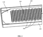
FIG. 1 is a perspective view of a portion of a component contacting a braze gel in an embodiment of the present disclosure. -
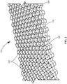
FIG. 2 is a perspective view of a brazing article, including the component ofFIG. 1 partially coated with a dried braze coating. -
FIG. 3 is a schematic cross sectional view of the brazing article ofFIG. 2 and a backing member ready to be brazed together. -
FIG. 4 is a perspective view of a brazed article including the brazing article and backing member ofFIG. 3 . - Wherever possible, the same reference numbers will be used throughout the drawings to represent the same parts.
- Provided are exemplary braze gels, brazing processes, and brazing articles. Embodiments of the present disclosure, in comparison to compositions, processes, and articles not using one or more of the features described herein, provide a braze gel having a lower viscosity than conventional braze pastes, replace braze tape for honeycomb brazing, provide honeycomb brazing without using braze tape, provide an inexpensive braze coating, provide a braze coating to a component having small structural features, provide a braze gel that sticks to a component surface better than a conventional braze paste, or a combination thereof.
- Referring to
FIG. 1 , a brazing process includes contacting a first end 102 (seeFIG. 2 ) of acomponent 100 to abraze gel 110 to coat a portion of thecomponent 100, including thefirst end 102, with thebraze gel 110.FIG. 1 shows a dip coating method, where thebraze gel 110 is held in acontainer 120, but other contacting methods may be employed, including, but not limited to, spray coating or brush coating. Thecomponent 100 includesstructural features 106 in the form of honeycomb cells. Thebraze gel 110 coats thefirst end 102 of thecomponent 100, but thebraze gel 110 does not contact thesecond end 104 of thecomponent 100. After thebraze gel 110 is applied to thefirst end 102 of thecomponent 100, thecomponent 100 is removed from thecontainer 120 and thebraze gel 110 is allowed to dry on the coated surface of thecomponent 100. In some embodiments, thecomponent 100 is turned upside-down such that thebraze gel 110 is on the upper portion of thecomponent 100 during drying. In some embodiments, thecomponent 100 is held with the coated surface being the lower portion of thecomponent 100 during drying. The drying may occur under ambient temperature and air conditions, or heating, air flow, and/or a vacuum may be used to decrease the drying time. -
FIG. 2 shows abrazing article 125, which includes thecomponent 100 and abraze coating 130 dried on the coatedportion 108, including thefirst end 102 of thecomponent 100. Thefirst end 102 of thecomponent 100, which is the upper end as shown inFIG. 2 , is ready to be brazed to a backing member 140 (seeFIG. 3 ). Thebrazing article 125 is flipped over, with thefirst end 102 facing thebacking member 140, and thecomponent 100 is then brazed to thebacking member 140. - In
FIG. 3 , anybraze coating 130 on thefirst end 102 of thestructural features 106 of thecomponent 100 has been mostly or substantially removed to permit direct contact between thestructural features 106 and thebacking member 140 prior to brazing. As shown inFIG. 3 , thebraze coating 130 forms only a thin layer over thestructural features 106. The thickness of thebraze coating 130 is preferably selected to provide enough material to form a good braze between thecomponent 100 and thebacking member 140 while providing no more than a predetermined excess amount of braze material to limit waste. Thebraze coating 130 does not span the space between thestructural features 106. Tack welding may be used to temporarily attach thecomponent 100 to thebacking member 140 prior to brazing. - Brazing is then performed by heating the
braze coating 130 to a braze temperature to melt thebraze coating 130. In some embodiments, the assembly of thebrazing article 125 and thebacking member 140 placed in a furnace to heat thebraze coating 130 to the braze temperature. At least a portion of the melted braze material from thebraze coating 130 flows between thefirst end 102 of thestructural features 106 and thebacking member 140 to braze thecomponent 100 to thebacking member 140. -
FIG. 4 shows a brazedarticle 150 including thecomponent 100 brazed to thebacking member 140. Thecomponent 100 is brazed well to thebacking member 140 with an even brazing and without having anybraze material 112 at or near thesecond end 104 opposite thecoated portion 108 of thecomponent 100. A thin layer ofbraze material 112 may remain on the lower portion of the sidewalls of thestructural features 106 of thecomponent 100 after brazing. - A
braze gel 110 includes at least one braze powder, at least one braze binder, and at least one viscosity reducer. In some embodiments, thebraze gel 110 has a gel viscosity less than a paste viscosity of a braze paste including the braze powder and the braze binder with no viscosity reducer. In some embodiments, thebraze gel 110 has a gel viscosity sufficiently low to permit dip coating of acomponent 100 to apply a coating of thebraze gel 110 to thecomponent 100. In some embodiments, thebraze gel 110 has a gel viscosity sufficiently low to permit spray coating of acomponent 100 to apply a coating of thebraze gel 110 to thecomponent 100. In some embodiments, thebraze gel 110 has a gel viscosity sufficiently low to permit brush coating of acomponent 100 to apply a coating of thebraze gel 110 to thecomponent 100. In some embodiments, thebraze gel 110 has a gel-like consistency. The viscosity reducer is preferably present in the range of about 0.1% to about 5%, by weight, of thebraze gel 110. In some embodiments, the viscosity reducer is mixed with a braze paste of the braze powder and the braze binder to form thebraze gel 110. In other embodiments, the braze powder, the braze binder, and the viscosity reducer may be combined and mixed in any order and in any number of steps or stages to achieve thebraze gel 110. - A braze powder, as used herein, refers to any metal powder composition melting at a brazing temperature below a melting temperature of a base material to which the braze is applied.
- A braze binder, as used herein, refers to any composition that serves as a carrier for mixing with a braze powder to make a braze paste.
- A viscosity reducer, as used herein, refers to any composition that, when mixed with a braze paste, including at least one braze powder and at least one braze binder, reduces the viscosity of the braze paste.
- A braze gel, as used herein, refers to any composition including at least one braze powder, at least one braze binder, and at least one viscosity reducer. In some embodiments, the viscosity reducer is present in an amount sufficient to give the braze gel a gel viscosity sufficiently low to permit dip coating of a component with the braze gel to apply a coating of the braze gel to the component. In some embodiments, the viscosity reducer is present in an amount sufficient to give the braze gel a gel viscosity sufficiently low to permit spray coating of a component with the braze gel to apply a coating of the braze gel to the component. In some embodiments, the viscosity reducer is present in an amount sufficient to give the braze gel a gel viscosity sufficiently low to permit brush coating of a component with the braze gel to apply a coating of the braze gel to the component.
- In some embodiments, the
component 100 is a turbine component. In some embodiments, the turbine component is part of a labyrinth seal, a shroud seal, or a diaphragm seal. - The
braze gel 110 may include about 40% to about 95% braze powder, up to about 59.9% braze binder, and about 0.1 to about 5% viscosity reducer, by weight; alternatively greater than about 60% to about 80% braze powder, about 15% to about 39.9% braze binder, and about 0.1% to about 5% viscosity reducer, by weight; alternatively about 70% to about 75% braze powder, about 20% to about 29.9% braze binder, and about 0.1% to about 5% viscosity reducer, by weight; alternatively the braze powder and the braze binder in a 3:1 ratio, by weight, alternatively about 75% braze powder, about 20.9% to about 25% braze binder, and about 0.1% to about 5% viscosity reducer, by weight; or any range or sub-range therebetween. - The
braze gel 110 includes, by weight, about 0.1% to about 5% viscosity reducer, alternatively about 1% to about 4% viscosity reducer, alternatively about 2% to about 3% viscosity reducer, alternatively about 0.1% to about 1% viscosity reducer, alternatively about 4% to about 5% viscosity reducer, or any range or sub-range therebetween. - The composition of the braze powder may include, but is not limited to, aluminum, cobalt, a silver-based braze alloy, a gold-based braze alloy, a copper-based braze alloy, a nickel-based braze alloy, an aluminum-based braze alloy, a cobalt-based alloy, a nickel-based alloy, or a combination thereof.
- In some embodiments, the binder includes an organic polymer. In some embodiments, the binder includes a waterborne acrylic resin-based binder. In some embodiments, the binder includes water, polyvinyl alcohol, isopropanol, 4-methyl-2-pentanone, or a combination thereof.
- The viscosity reducer may include, but is not limited to, ammonium chloride (NH4Cl), ammonium fluoride (NH4F), ammonium bromide (NH4Br), chromium (II) chloride (CrCl2), chromium (III) chloride (CrCl3), aluminum chloride (AlCl3), or a combination thereof.
- The
component 100 may be made of any high-temperature metal, which may include, but is not limited to, a nickel-based alloy, a cobalt-based alloy, or combinations thereof. In some embodiments, thebraze gel 110 is applied directly to the base metal material of thecomponent 100. In other embodiments, an aluminide coating is applied to the base metal material before thebraze gel 110 is applied to thecomponent 100. - In some embodiments, the
structural features 106 are metal foils. Thestructural features 106 may have a spacing dimension of less than about 5 mm, alternatively less than about 4 mm, alternatively less than about 3 mm, alternatively less than about 2 mm, or alternatively less than about 1 mm. Thestructural features 106 may have a depth of at least about 1 mm, alternatively at least about 1.5 mm, alternatively at least about 2 mm, alternatively at least about 3 mm, or alternatively at least about 5 mm. In some embodiments, thestructural features 106 make up less than about 10%, alternatively less than about 8%, alternatively less than about 5%, alternatively less than about 3%, alternatively less than about 1%, or any range or sub-range thereof, of the cross sectional area of thecomponent 100, with the remaining area being open or void space. In some embodiments, the metal foils have a honeycomb geometry. - In some embodiments, the
braze gel 110 has substantially about the same braze powder content as in a conventional braze paste but with a much lower viscosity at ambient temperature than the conventional braze paste so that acomponent 100 havingstructural features 106 is easily dipped into thebraze gel 110 in acontainer 120 to apply thebraze gel 110 to the submerged surfaces of thecomponent 100. In some embodiments, thecomponent 100 is a honeycomb component. After dipping, thecomponent 100 is removed from thecontainer 120. The dipped portion of thecomponent 100 is covered with a fairly thin, fairly uniform layer of thebraze gel 110. Thebraze gel 110 is allowed to dry to a fairly thin, fairly uniform layer of abraze coating 130 on thecomponent 100. The component is then brazed to abacking member 140. In some embodiments, the brazing is a furnace brazing. In some embodiments, the brazing is a vacuum brazing. - The
braze gel 110 sticks well to thecomponent 100 during application, preferably better than a conventional brazing paste. Thebraze coating 130 dried on thecomponent 100 also sticks strongly to the surface of thecomponent 100. - A brazing process includes applying a
braze gel 110, including a braze powder, a braze binder, and a viscosity reducer, to acomponent 100. The brazing process further includes allowing thebraze gel 110 to dry to abraze coating 130 on the surface of the component. In some embodiments, the brazing process also includes mixing the braze powder, the braze binder, and the viscosity reducer to form thebraze gel 110. In some embodiments, the brazing process also includes tack welding thecomponent 100 to abacking member 140 and brazing thecomponent 100 to thebacking member 140. - In some embodiments, a suitable braze temperature is at least about 815 °C (about 1500 °F), alternatively at least about 1090 °C (about 2000 °F), alternatively at least about 1150 °C (about 2100 °F), alternatively at least about 1175 °C (about 2150 °F), alternatively at least about 1190 °C (about 2175 °F), alternatively in the range of about 815 °C to about 1230 °C (about 1500 °F to about 2250 °F), alternatively in the range of about 815 °C to about 1090 °C (about 1500 °F to about 2000 °F), alternatively in the range of about 1090 °C to about 1370 °C (about 2000 °F to about 2500 °F), alternatively in the range of about 1150 °C to about 1290 °C (about 2100 °F to about 2350 °F), alternatively in the range of about 1175 °C to about 1230 °C (about 2150 °F to about 2250 °F), alternatively in the range of about 1190 °C to about 1230 °C
- (about 2175 °F to about 2250 °F), or any combination, sub-combination, range, or sub-range thereof.
- While the invention has been described with reference to a preferred embodiment, it will be understood by those skilled in the art that various changes may be made and equivalents may be substituted for elements thereof without departing from the scope of the invention. In addition, many modifications may be made to adapt a particular situation or material to the teachings of the invention without departing from the essential scope thereof. Therefore, it is intended that the invention not be limited to the particular embodiment disclosed as the best mode contemplated for carrying out this invention, but that the invention will include all embodiments falling within the scope of the appended claims.
- Various aspects and embodiments of the present invention are defined by the following clauses:
- 1. A braze gel, comprising:
- a braze powder;
- a braze binder; and
- a viscosity reducer;
- wherein the braze gel has a gel viscosity sufficiently low to permit dip coating of a component with the braze gel to apply a braze coating of the braze gel to the component.
- 2. The braze gel of clause 1, wherein the viscosity reducer is selected from the group consisting of ammonium chloride, ammonium fluoride, ammonium bromide, chromium (II) chloride, chromium (III) chloride, aluminum chloride, and a combination thereof.
- 3. The braze gel of clause 1, wherein the viscosity reducer is about 0.1% to about 5% of the braze gel, by weight.
- 4. The braze gel of clause 3, wherein the braze powder is about 40% to about 95% and the braze binder is up to about 59.9% of the braze gel, by weight.
- 5. The braze gel of clause 3, wherein the braze powder is greater than about 60% to about 80% and the braze binder is about 15% to about 39.9% of the braze gel, by weight.
- 6. The braze gel of clause 3, wherein the braze powder is about 70% to about 75% and the braze binder is about 20% to about 29.9% of the braze gel, by weight.
- 7. A brazing process, comprising:
- applying a braze gel comprising a braze powder, a braze binder, and a viscosity reducer to a portion of a component; and
- drying the braze gel to form a braze coating on the component to form a braze-coated component;
- wherein the braze gel has a gel viscosity sufficiently low to permit dip coating of a component with the braze gel to apply the braze coating of the braze gel to the component.
- 8. The brazing process of clause 7 further comprising combining the braze powder, the braze binder, and the viscosity reducer to form the braze gel.
- 9. The brazing process of clause 7 further comprising brazing the braze-coated component to a backing member.
- 10. The brazing process of clause 9, wherein the brazing is performed at a brazing temperature in the range of about 815 °C to about 1230 °C (about 1500 °F to about 2250 °F).
- 11. The brazing process of clause 7, wherein the applying comprises dip coating the braze gel on the portion of the component.
- 12. The brazing process of clause 7, wherein the applying comprises spray coating the braze gel on the portion of the component.
- 13. The brazing process of clause 7, wherein the component comprises a plurality of honeycomb cells.
- 14. A brazing article, comprising:
- a component; and
- a braze coating over a portion of the component, the braze coating having dried from braze gel comprising:
- a braze powder;
- a braze binder; and
- a viscosity reducer;
- wherein the braze gel has a gel viscosity sufficiently low to permit dip coating of the component with the braze gel to apply the braze gel to the component.
- 15. The brazing article of clause 14, wherein the viscosity reducer is about 0.1% to about 5% of the braze gel, by weight.
- 16. The brazing article of clause 14, wherein the braze powder is about 40% to about 95% and the braze binder is up to about 59.9% of the braze gel, by weight.
- 17. The brazing article of clause 14, wherein the braze powder is greater than about 60% to about 80% and the braze binder is about 15% to about 39.9% of the braze gel, by weight.
- 18. The brazing article of clause 14, wherein the component comprises structural features having a spacing of less than about 5 mm and a depth of at least about 1 mm.
- 19. The brazing article of clause 14, wherein the component comprises a plurality of honeycomb cells.
- 20. The brazing article of clause 14, wherein the component forms at least a portion of a turbine component selected from the group consisting of a labyrinth seal, a shroud seal, and a diaphragm seal.
Claims (10)
- A braze gel (110), comprising:a braze powder;a braze binder; anda viscosity reducer;wherein the braze gel (110) has a gel viscosity sufficiently low to permit dip coating of a component (100) with the braze gel (110) to apply a braze coating (130) of the braze gel (110) to the component (100).
- The braze gel (110) of claim 1, wherein the viscosity reducer is selected from the group consisting of ammonium chloride, ammonium fluoride, ammonium bromide, chromium (II) chloride, chromium (III) chloride, aluminum chloride, and a combination thereof.
- The braze gel (110) of claim 1 or 2, wherein the viscosity reducer is about 0.1% to about 5% of the braze gel (110), by weight.
- The braze gel (110) of any one of claims 1 to 3, wherein the braze powder is about 40% to about 95% and the braze binder is up to about 59.5% of the braze gel (110), by weight.
- A brazing process, comprising:applying a braze gel (110) comprising a braze powder, a braze binder, and a viscosity reducer to a portion of a component (100); anddrying the braze gel (110) to form a braze coating (130) on the component (100) to form a braze-coated component (125);wherein the braze gel (110) has a gel viscosity sufficiently low to permit dip coating of a component (100) with the braze gel (110) to apply the braze coating (130) of the braze gel (110) to the component (100).
- The brazing process of claim 5 further comprising brazing the braze-coated component (125) to a backing member (140).
- The brazing process of claim 5 or 6, wherein the brazing is performed at a brazing temperature in the range of about 815 °C to about 1230 °C (about 1500 °F to about 2250 °F).
- A brazing article (125), comprising:a component (100); anda braze coating (130) over a portion of the component (100), the braze coating (130) having dried from a braze gel (110) comprising:a braze powder;a braze binder; anda viscosity reducer;wherein the braze gel (110) has a gel viscosity sufficiently low to permit dip coating of the component (100) with the braze gel (110) to apply the braze gel (110) to the component (100).
- The brazing article (125) of claim 8, wherein the component (100) comprises a plurality of honeycomb cells.
- The brazing article (125) of claim 8 or 9, wherein the component (100) forms at least a portion of a turbine component selected from the group consisting of a labyrinth seal, a shroud seal, and a diaphragm seal.
Applications Claiming Priority (1)
| Application Number | Priority Date | Filing Date | Title |
|---|---|---|---|
| US15/271,960 US10024185B2 (en) | 2016-09-21 | 2016-09-21 | Braze gel, brazing process, and brazing article |
Publications (2)
| Publication Number | Publication Date |
|---|---|
| EP3299114A1 true EP3299114A1 (en) | 2018-03-28 |
| EP3299114B1 EP3299114B1 (en) | 2020-01-29 |
Family
ID=59930205
Family Applications (1)
| Application Number | Title | Priority Date | Filing Date |
|---|---|---|---|
| EP17192116.6A Active EP3299114B1 (en) | 2016-09-21 | 2017-09-20 | Braze gel, brazing process, and brazing article |
Country Status (3)
| Country | Link |
|---|---|
| US (1) | US10024185B2 (en) |
| EP (1) | EP3299114B1 (en) |
| JP (1) | JP7053197B2 (en) |
Cited By (2)
| Publication number | Priority date | Publication date | Assignee | Title |
|---|---|---|---|---|
| CN110732842A (en) * | 2019-10-23 | 2020-01-31 | 佛山市桐立新材料科技有限公司 | Preparation method of brazing aluminum honeycomb plate |
| EP4063062A1 (en) * | 2021-02-26 | 2022-09-28 | Raytheon Technologies Corporation | Repair methods and systems for honeycomb structures in gas turbine engines |
Families Citing this family (6)
| Publication number | Priority date | Publication date | Assignee | Title |
|---|---|---|---|---|
| US11149354B2 (en) | 2019-02-20 | 2021-10-19 | General Electric Company | Dense abradable coating with brittle and abradable components |
| US11298768B2 (en) | 2019-11-15 | 2022-04-12 | Rolls-Royce Corporation | Method of preparing a surface for diffusion bonding and method of diffusion bonding |
| US11565336B2 (en) | 2019-11-15 | 2023-01-31 | Rolls-Royce North American Technologies Inc. | Method of selectively bonding braze powders to a surface |
| US11420279B2 (en) | 2019-11-15 | 2022-08-23 | Rolls-Royce Corporation | Method of selectively bonding braze powders to a surface |
| US11571762B2 (en) | 2019-11-15 | 2023-02-07 | Rolls-Royce North American Technologies Inc. | Printing method to selectively deposit braze powders at one or more predetermined locations on a surface |
| CN118848338B (en) * | 2024-08-28 | 2025-04-25 | 佛山市诺普材料科技有限公司 | Gel type brazing material for brazing and preparation method and application thereof |
Citations (5)
| Publication number | Priority date | Publication date | Assignee | Title |
|---|---|---|---|---|
| US4431465A (en) * | 1981-06-04 | 1984-02-14 | Gte Products Corporation | Brazing alloy paste |
| US5120374A (en) * | 1990-05-11 | 1992-06-09 | The Morgan Crucible Company Plc | Gel for brazing filler metal paste |
| US5443658A (en) * | 1994-06-08 | 1995-08-22 | Praxair S.T. Technology, Inc. | Braze filler metal alloy paste |
| CN101100601A (en) * | 2007-07-31 | 2008-01-09 | 中国石油天然气股份有限公司 | Corrosion-inhibition scale-inhibition paraffin-removal viscosity reducer and preparation method thereof |
| US20130064602A1 (en) * | 2010-03-16 | 2013-03-14 | Commissariat a l'energie atomique et aux énergies | METHOD OF JOINING PARTS MADE OF SiC-BASED MATERIALS BY NON-REACTIVE BRAZING WITH ADDITION OF A REINFORCEMENT. BRAZING COMPOSITIONS AND JOINT AND ASSEMBLY THAT ARE OBTAINED BY SUCH A METHOD |
Family Cites Families (14)
| Publication number | Priority date | Publication date | Assignee | Title |
|---|---|---|---|---|
| US3023127A (en) * | 1953-05-25 | 1962-02-27 | Peen Plate Inc | Metal coating process |
| US3001274A (en) * | 1957-01-18 | 1961-09-26 | Solar Aircraft Co | Brazing article and method |
| US3073270A (en) * | 1960-12-05 | 1963-01-15 | Glidden Co | Brazing pastes |
| US3166402A (en) * | 1963-09-24 | 1965-01-19 | Powder Melting Corp | Brazing compositions having polyvinyl butyral as a binder |
| US3527625A (en) * | 1967-12-05 | 1970-09-08 | Gilman B Mollring | Soldering paste |
| US4151016A (en) | 1976-09-17 | 1979-04-24 | Fusion Incorporated | Single component brazing paste |
| DE2924592C2 (en) * | 1979-06-19 | 1983-05-26 | Süddeutsche Kühlerfabrik Julius Fr. Behr GmbH & Co KG, 7000 Stuttgart | Method for producing a carrier matrix for a catalytic reactor for exhaust gas purification in internal combustion engines of motor vehicles |
| US6367686B1 (en) | 2000-08-31 | 2002-04-09 | United Technologies Corporation | Self cleaning braze material |
| US8776371B2 (en) * | 2002-05-03 | 2014-07-15 | Alfa Laval Corporate Ab | Method of brazing thin heat exchanging plates and brazed plate heat exchanger produced according to the method |
| DE102005053553A1 (en) * | 2005-11-08 | 2007-05-16 | Heraeus Gmbh W C | Solder pastes with resin-free flux |
| US20080053645A1 (en) | 2006-08-31 | 2008-03-06 | Denso Corporation | Heat exchanger and manufacture method for the same |
| US20090214773A1 (en) | 2008-02-27 | 2009-08-27 | General Electric Company | Diffusion Coating Systems with Binders that Enhance Coating Gas |
| WO2013109968A1 (en) | 2012-01-18 | 2013-07-25 | Holtec International, Inc. | Finned tube assemblies for heat exchangers |
| US8973808B2 (en) * | 2012-01-05 | 2015-03-10 | General Electric Company | Method for making a cellular seal |
-
2016
- 2016-09-21 US US15/271,960 patent/US10024185B2/en active Active
-
2017
- 2017-09-12 JP JP2017174429A patent/JP7053197B2/en active Active
- 2017-09-20 EP EP17192116.6A patent/EP3299114B1/en active Active
Patent Citations (5)
| Publication number | Priority date | Publication date | Assignee | Title |
|---|---|---|---|---|
| US4431465A (en) * | 1981-06-04 | 1984-02-14 | Gte Products Corporation | Brazing alloy paste |
| US5120374A (en) * | 1990-05-11 | 1992-06-09 | The Morgan Crucible Company Plc | Gel for brazing filler metal paste |
| US5443658A (en) * | 1994-06-08 | 1995-08-22 | Praxair S.T. Technology, Inc. | Braze filler metal alloy paste |
| CN101100601A (en) * | 2007-07-31 | 2008-01-09 | 中国石油天然气股份有限公司 | Corrosion-inhibition scale-inhibition paraffin-removal viscosity reducer and preparation method thereof |
| US20130064602A1 (en) * | 2010-03-16 | 2013-03-14 | Commissariat a l'energie atomique et aux énergies | METHOD OF JOINING PARTS MADE OF SiC-BASED MATERIALS BY NON-REACTIVE BRAZING WITH ADDITION OF A REINFORCEMENT. BRAZING COMPOSITIONS AND JOINT AND ASSEMBLY THAT ARE OBTAINED BY SUCH A METHOD |
Cited By (3)
| Publication number | Priority date | Publication date | Assignee | Title |
|---|---|---|---|---|
| CN110732842A (en) * | 2019-10-23 | 2020-01-31 | 佛山市桐立新材料科技有限公司 | Preparation method of brazing aluminum honeycomb plate |
| EP4063062A1 (en) * | 2021-02-26 | 2022-09-28 | Raytheon Technologies Corporation | Repair methods and systems for honeycomb structures in gas turbine engines |
| US11819966B2 (en) | 2021-02-26 | 2023-11-21 | Rtx Corporation | Repair methods and systems for honeycomb structures in gas turbine engines |
Also Published As
| Publication number | Publication date |
|---|---|
| EP3299114B1 (en) | 2020-01-29 |
| US20180080336A1 (en) | 2018-03-22 |
| JP2018086680A (en) | 2018-06-07 |
| JP7053197B2 (en) | 2022-04-12 |
| US10024185B2 (en) | 2018-07-17 |
Similar Documents
| Publication | Publication Date | Title |
|---|---|---|
| EP3299114B1 (en) | Braze gel, brazing process, and brazing article | |
| US6283356B1 (en) | Repair of a recess in an article surface | |
| US6045863A (en) | Low activity localized aluminide coating | |
| CA2204811C (en) | Method for repairing a nickel base superalloy article | |
| EP1721697B1 (en) | Superalloy repair methods and inserts | |
| US7343676B2 (en) | Method of restoring dimensions of an airfoil and preform for performing same | |
| US7966707B2 (en) | Method for repairing superalloy components using inserts | |
| US6060174A (en) | Bond coats for turbine components and method of applying the same | |
| EP2612951B1 (en) | Method for making a honeycomb seal | |
| EP1839800B1 (en) | Method for local application of diffusion aluminide coating | |
| EP1759799A2 (en) | Superalloy repair methods | |
| JPS6389607A (en) | Method for adding alloy to metal article | |
| US6910620B2 (en) | Method for providing turbulation on the inner surface of holes in an article, and related articles | |
| US6299935B1 (en) | Method for forming a coating by use of an activated foam technique | |
| WO2014169116A1 (en) | Wide gap braze | |
| US20050265851A1 (en) | Active elements modified chromium diffusion patch coating | |
| US6511630B1 (en) | Method for forming a coating by use of foam technique | |
| JP7608066B2 (en) | Method for repairing superalloy components using phase coagulation - Patents.com | |
| US20030111140A1 (en) | Process for producing a cladding for a metallic component | |
| US20080142122A1 (en) | Niobium-silicide alloys having a surface region of enhanced environmental-resistance, and related articles and processes |
Legal Events
| Date | Code | Title | Description |
|---|---|---|---|
| PUAI | Public reference made under article 153(3) epc to a published international application that has entered the european phase |
Free format text: ORIGINAL CODE: 0009012 |
|
| STAA | Information on the status of an ep patent application or granted ep patent |
Free format text: STATUS: THE APPLICATION HAS BEEN PUBLISHED |
|
| AK | Designated contracting states |
Kind code of ref document: A1 Designated state(s): AL AT BE BG CH CY CZ DE DK EE ES FI FR GB GR HR HU IE IS IT LI LT LU LV MC MK MT NL NO PL PT RO RS SE SI SK SM TR |
|
| AX | Request for extension of the european patent |
Extension state: BA ME |
|
| STAA | Information on the status of an ep patent application or granted ep patent |
Free format text: STATUS: REQUEST FOR EXAMINATION WAS MADE |
|
| 17P | Request for examination filed |
Effective date: 20180928 |
|
| RBV | Designated contracting states (corrected) |
Designated state(s): AL AT BE BG CH CY CZ DE DK EE ES FI FR GB GR HR HU IE IS IT LI LT LU LV MC MK MT NL NO PL PT RO RS SE SI SK SM TR |
|
| RIC1 | Information provided on ipc code assigned before grant |
Ipc: B23K 35/28 20060101ALI20190528BHEP Ipc: B23K 1/00 20060101ALI20190528BHEP Ipc: B23K 35/365 20060101ALI20190528BHEP Ipc: B23K 35/02 20060101ALI20190528BHEP Ipc: F01D 11/02 20060101ALI20190528BHEP Ipc: B23K 35/30 20060101ALI20190528BHEP Ipc: F01D 11/00 20060101ALI20190528BHEP Ipc: B23K 35/36 20060101AFI20190528BHEP |
|
| GRAP | Despatch of communication of intention to grant a patent |
Free format text: ORIGINAL CODE: EPIDOSNIGR1 |
|
| STAA | Information on the status of an ep patent application or granted ep patent |
Free format text: STATUS: GRANT OF PATENT IS INTENDED |
|
| INTG | Intention to grant announced |
Effective date: 20190705 |
|
| GRAS | Grant fee paid |
Free format text: ORIGINAL CODE: EPIDOSNIGR3 |
|
| GRAJ | Information related to disapproval of communication of intention to grant by the applicant or resumption of examination proceedings by the epo deleted |
Free format text: ORIGINAL CODE: EPIDOSDIGR1 |
|
| GRAL | Information related to payment of fee for publishing/printing deleted |
Free format text: ORIGINAL CODE: EPIDOSDIGR3 |
|
| STAA | Information on the status of an ep patent application or granted ep patent |
Free format text: STATUS: REQUEST FOR EXAMINATION WAS MADE |
|
| GRAR | Information related to intention to grant a patent recorded |
Free format text: ORIGINAL CODE: EPIDOSNIGR71 |
|
| STAA | Information on the status of an ep patent application or granted ep patent |
Free format text: STATUS: GRANT OF PATENT IS INTENDED |
|
| INTC | Intention to grant announced (deleted) | ||
| GRAA | (expected) grant |
Free format text: ORIGINAL CODE: 0009210 |
|
| STAA | Information on the status of an ep patent application or granted ep patent |
Free format text: STATUS: THE PATENT HAS BEEN GRANTED |
|
| INTG | Intention to grant announced |
Effective date: 20191211 |
|
| AK | Designated contracting states |
Kind code of ref document: B1 Designated state(s): AL AT BE BG CH CY CZ DE DK EE ES FI FR GB GR HR HU IE IS IT LI LT LU LV MC MK MT NL NO PL PT RO RS SE SI SK SM TR |
|
| REG | Reference to a national code |
Ref country code: GB Ref legal event code: FG4D |
|
| REG | Reference to a national code |
Ref country code: CH Ref legal event code: EP |
|
| REG | Reference to a national code |
Ref country code: AT Ref legal event code: REF Ref document number: 1228134 Country of ref document: AT Kind code of ref document: T Effective date: 20200215 |
|
| REG | Reference to a national code |
Ref country code: IE Ref legal event code: FG4D |
|
| REG | Reference to a national code |
Ref country code: DE Ref legal event code: R096 Ref document number: 602017011126 Country of ref document: DE |
|
| REG | Reference to a national code |
Ref country code: NL Ref legal event code: MP Effective date: 20200129 |
|
| PG25 | Lapsed in a contracting state [announced via postgrant information from national office to epo] |
Ref country code: PT Free format text: LAPSE BECAUSE OF FAILURE TO SUBMIT A TRANSLATION OF THE DESCRIPTION OR TO PAY THE FEE WITHIN THE PRESCRIBED TIME-LIMIT Effective date: 20200621 Ref country code: NO Free format text: LAPSE BECAUSE OF FAILURE TO SUBMIT A TRANSLATION OF THE DESCRIPTION OR TO PAY THE FEE WITHIN THE PRESCRIBED TIME-LIMIT Effective date: 20200429 Ref country code: RS Free format text: LAPSE BECAUSE OF FAILURE TO SUBMIT A TRANSLATION OF THE DESCRIPTION OR TO PAY THE FEE WITHIN THE PRESCRIBED TIME-LIMIT Effective date: 20200129 Ref country code: FI Free format text: LAPSE BECAUSE OF FAILURE TO SUBMIT A TRANSLATION OF THE DESCRIPTION OR TO PAY THE FEE WITHIN THE PRESCRIBED TIME-LIMIT Effective date: 20200129 |
|
| REG | Reference to a national code |
Ref country code: LT Ref legal event code: MG4D |
|
| PG25 | Lapsed in a contracting state [announced via postgrant information from national office to epo] |
Ref country code: BG Free format text: LAPSE BECAUSE OF FAILURE TO SUBMIT A TRANSLATION OF THE DESCRIPTION OR TO PAY THE FEE WITHIN THE PRESCRIBED TIME-LIMIT Effective date: 20200429 Ref country code: IS Free format text: LAPSE BECAUSE OF FAILURE TO SUBMIT A TRANSLATION OF THE DESCRIPTION OR TO PAY THE FEE WITHIN THE PRESCRIBED TIME-LIMIT Effective date: 20200529 Ref country code: LV Free format text: LAPSE BECAUSE OF FAILURE TO SUBMIT A TRANSLATION OF THE DESCRIPTION OR TO PAY THE FEE WITHIN THE PRESCRIBED TIME-LIMIT Effective date: 20200129 Ref country code: SE Free format text: LAPSE BECAUSE OF FAILURE TO SUBMIT A TRANSLATION OF THE DESCRIPTION OR TO PAY THE FEE WITHIN THE PRESCRIBED TIME-LIMIT Effective date: 20200129 Ref country code: GR Free format text: LAPSE BECAUSE OF FAILURE TO SUBMIT A TRANSLATION OF THE DESCRIPTION OR TO PAY THE FEE WITHIN THE PRESCRIBED TIME-LIMIT Effective date: 20200430 Ref country code: HR Free format text: LAPSE BECAUSE OF FAILURE TO SUBMIT A TRANSLATION OF THE DESCRIPTION OR TO PAY THE FEE WITHIN THE PRESCRIBED TIME-LIMIT Effective date: 20200129 |
|
| PG25 | Lapsed in a contracting state [announced via postgrant information from national office to epo] |
Ref country code: NL Free format text: LAPSE BECAUSE OF FAILURE TO SUBMIT A TRANSLATION OF THE DESCRIPTION OR TO PAY THE FEE WITHIN THE PRESCRIBED TIME-LIMIT Effective date: 20200129 |
|
| PG25 | Lapsed in a contracting state [announced via postgrant information from national office to epo] |
Ref country code: ES Free format text: LAPSE BECAUSE OF FAILURE TO SUBMIT A TRANSLATION OF THE DESCRIPTION OR TO PAY THE FEE WITHIN THE PRESCRIBED TIME-LIMIT Effective date: 20200129 Ref country code: CZ Free format text: LAPSE BECAUSE OF FAILURE TO SUBMIT A TRANSLATION OF THE DESCRIPTION OR TO PAY THE FEE WITHIN THE PRESCRIBED TIME-LIMIT Effective date: 20200129 Ref country code: DK Free format text: LAPSE BECAUSE OF FAILURE TO SUBMIT A TRANSLATION OF THE DESCRIPTION OR TO PAY THE FEE WITHIN THE PRESCRIBED TIME-LIMIT Effective date: 20200129 Ref country code: RO Free format text: LAPSE BECAUSE OF FAILURE TO SUBMIT A TRANSLATION OF THE DESCRIPTION OR TO PAY THE FEE WITHIN THE PRESCRIBED TIME-LIMIT Effective date: 20200129 Ref country code: SM Free format text: LAPSE BECAUSE OF FAILURE TO SUBMIT A TRANSLATION OF THE DESCRIPTION OR TO PAY THE FEE WITHIN THE PRESCRIBED TIME-LIMIT Effective date: 20200129 Ref country code: EE Free format text: LAPSE BECAUSE OF FAILURE TO SUBMIT A TRANSLATION OF THE DESCRIPTION OR TO PAY THE FEE WITHIN THE PRESCRIBED TIME-LIMIT Effective date: 20200129 Ref country code: SK Free format text: LAPSE BECAUSE OF FAILURE TO SUBMIT A TRANSLATION OF THE DESCRIPTION OR TO PAY THE FEE WITHIN THE PRESCRIBED TIME-LIMIT Effective date: 20200129 Ref country code: LT Free format text: LAPSE BECAUSE OF FAILURE TO SUBMIT A TRANSLATION OF THE DESCRIPTION OR TO PAY THE FEE WITHIN THE PRESCRIBED TIME-LIMIT Effective date: 20200129 |
|
| REG | Reference to a national code |
Ref country code: DE Ref legal event code: R097 Ref document number: 602017011126 Country of ref document: DE |
|
| REG | Reference to a national code |
Ref country code: AT Ref legal event code: MK05 Ref document number: 1228134 Country of ref document: AT Kind code of ref document: T Effective date: 20200129 |
|
| PLBE | No opposition filed within time limit |
Free format text: ORIGINAL CODE: 0009261 |
|
| STAA | Information on the status of an ep patent application or granted ep patent |
Free format text: STATUS: NO OPPOSITION FILED WITHIN TIME LIMIT |
|
| 26N | No opposition filed |
Effective date: 20201030 |
|
| PG25 | Lapsed in a contracting state [announced via postgrant information from national office to epo] |
Ref country code: AT Free format text: LAPSE BECAUSE OF FAILURE TO SUBMIT A TRANSLATION OF THE DESCRIPTION OR TO PAY THE FEE WITHIN THE PRESCRIBED TIME-LIMIT Effective date: 20200129 |
|
| PG25 | Lapsed in a contracting state [announced via postgrant information from national office to epo] |
Ref country code: PL Free format text: LAPSE BECAUSE OF FAILURE TO SUBMIT A TRANSLATION OF THE DESCRIPTION OR TO PAY THE FEE WITHIN THE PRESCRIBED TIME-LIMIT Effective date: 20200129 Ref country code: SI Free format text: LAPSE BECAUSE OF FAILURE TO SUBMIT A TRANSLATION OF THE DESCRIPTION OR TO PAY THE FEE WITHIN THE PRESCRIBED TIME-LIMIT Effective date: 20200129 |
|
| REG | Reference to a national code |
Ref country code: CH Ref legal event code: PL |
|
| REG | Reference to a national code |
Ref country code: BE Ref legal event code: MM Effective date: 20200930 |
|
| PG25 | Lapsed in a contracting state [announced via postgrant information from national office to epo] |
Ref country code: LU Free format text: LAPSE BECAUSE OF NON-PAYMENT OF DUE FEES Effective date: 20200920 |
|
| PG25 | Lapsed in a contracting state [announced via postgrant information from national office to epo] |
Ref country code: FR Free format text: LAPSE BECAUSE OF NON-PAYMENT OF DUE FEES Effective date: 20200930 |
|
| PG25 | Lapsed in a contracting state [announced via postgrant information from national office to epo] |
Ref country code: BE Free format text: LAPSE BECAUSE OF NON-PAYMENT OF DUE FEES Effective date: 20200930 Ref country code: CH Free format text: LAPSE BECAUSE OF NON-PAYMENT OF DUE FEES Effective date: 20200930 Ref country code: IE Free format text: LAPSE BECAUSE OF NON-PAYMENT OF DUE FEES Effective date: 20200920 Ref country code: LI Free format text: LAPSE BECAUSE OF NON-PAYMENT OF DUE FEES Effective date: 20200930 |
|
| GBPC | Gb: european patent ceased through non-payment of renewal fee |
Effective date: 20210920 |
|
| PG25 | Lapsed in a contracting state [announced via postgrant information from national office to epo] |
Ref country code: TR Free format text: LAPSE BECAUSE OF FAILURE TO SUBMIT A TRANSLATION OF THE DESCRIPTION OR TO PAY THE FEE WITHIN THE PRESCRIBED TIME-LIMIT Effective date: 20200129 Ref country code: MT Free format text: LAPSE BECAUSE OF FAILURE TO SUBMIT A TRANSLATION OF THE DESCRIPTION OR TO PAY THE FEE WITHIN THE PRESCRIBED TIME-LIMIT Effective date: 20200129 Ref country code: CY Free format text: LAPSE BECAUSE OF FAILURE TO SUBMIT A TRANSLATION OF THE DESCRIPTION OR TO PAY THE FEE WITHIN THE PRESCRIBED TIME-LIMIT Effective date: 20200129 |
|
| PG25 | Lapsed in a contracting state [announced via postgrant information from national office to epo] |
Ref country code: MK Free format text: LAPSE BECAUSE OF FAILURE TO SUBMIT A TRANSLATION OF THE DESCRIPTION OR TO PAY THE FEE WITHIN THE PRESCRIBED TIME-LIMIT Effective date: 20200129 Ref country code: MC Free format text: LAPSE BECAUSE OF FAILURE TO SUBMIT A TRANSLATION OF THE DESCRIPTION OR TO PAY THE FEE WITHIN THE PRESCRIBED TIME-LIMIT Effective date: 20200129 Ref country code: AL Free format text: LAPSE BECAUSE OF FAILURE TO SUBMIT A TRANSLATION OF THE DESCRIPTION OR TO PAY THE FEE WITHIN THE PRESCRIBED TIME-LIMIT Effective date: 20200129 |
|
| PG25 | Lapsed in a contracting state [announced via postgrant information from national office to epo] |
Ref country code: GB Free format text: LAPSE BECAUSE OF NON-PAYMENT OF DUE FEES Effective date: 20210920 |
|
| REG | Reference to a national code |
Ref country code: DE Ref legal event code: R082 Ref document number: 602017011126 Country of ref document: DE Ref country code: DE Ref legal event code: R081 Ref document number: 602017011126 Country of ref document: DE Owner name: GENERAL ELECTRIC TECHNOLOGY GMBH, CH Free format text: FORMER OWNER: GENERAL ELECTRIC COMPANY, SCHENECTADY, NY, US |
|
| PGFP | Annual fee paid to national office [announced via postgrant information from national office to epo] |
Ref country code: DE Payment date: 20250820 Year of fee payment: 9 |
|
| PGFP | Annual fee paid to national office [announced via postgrant information from national office to epo] |
Ref country code: IT Payment date: 20250820 Year of fee payment: 9 |