EP3298396B1 - Pipe pig for inspecting a pipeline - Google Patents
Pipe pig for inspecting a pipeline Download PDFInfo
- Publication number
- EP3298396B1 EP3298396B1 EP16723493.9A EP16723493A EP3298396B1 EP 3298396 B1 EP3298396 B1 EP 3298396B1 EP 16723493 A EP16723493 A EP 16723493A EP 3298396 B1 EP3298396 B1 EP 3298396B1
- Authority
- EP
- European Patent Office
- Prior art keywords
- pipe
- pig
- pipe pig
- wall
- electromagnetic sensors
- Prior art date
- Legal status (The legal status is an assumption and is not a legal conclusion. Google has not performed a legal analysis and makes no representation as to the accuracy of the status listed.)
- Active
Links
Images
Classifications
-
- G—PHYSICS
- G01—MEASURING; TESTING
- G01N—INVESTIGATING OR ANALYSING MATERIALS BY DETERMINING THEIR CHEMICAL OR PHYSICAL PROPERTIES
- G01N27/00—Investigating or analysing materials by the use of electric, electrochemical, or magnetic means
- G01N27/72—Investigating or analysing materials by the use of electric, electrochemical, or magnetic means by investigating magnetic variables
- G01N27/82—Investigating or analysing materials by the use of electric, electrochemical, or magnetic means by investigating magnetic variables for investigating the presence of flaws
- G01N27/90—Investigating or analysing materials by the use of electric, electrochemical, or magnetic means by investigating magnetic variables for investigating the presence of flaws using eddy currents
- G01N27/904—Investigating or analysing materials by the use of electric, electrochemical, or magnetic means by investigating magnetic variables for investigating the presence of flaws using eddy currents with two or more sensors
-
- G—PHYSICS
- G01—MEASURING; TESTING
- G01N—INVESTIGATING OR ANALYSING MATERIALS BY DETERMINING THEIR CHEMICAL OR PHYSICAL PROPERTIES
- G01N27/00—Investigating or analysing materials by the use of electric, electrochemical, or magnetic means
- G01N27/72—Investigating or analysing materials by the use of electric, electrochemical, or magnetic means by investigating magnetic variables
- G01N27/82—Investigating or analysing materials by the use of electric, electrochemical, or magnetic means by investigating magnetic variables for investigating the presence of flaws
- G01N27/90—Investigating or analysing materials by the use of electric, electrochemical, or magnetic means by investigating magnetic variables for investigating the presence of flaws using eddy currents
- G01N27/9013—Arrangements for scanning
- G01N27/902—Arrangements for scanning by moving the sensors
-
- F—MECHANICAL ENGINEERING; LIGHTING; HEATING; WEAPONS; BLASTING
- F16—ENGINEERING ELEMENTS AND UNITS; GENERAL MEASURES FOR PRODUCING AND MAINTAINING EFFECTIVE FUNCTIONING OF MACHINES OR INSTALLATIONS; THERMAL INSULATION IN GENERAL
- F16L—PIPES; JOINTS OR FITTINGS FOR PIPES; SUPPORTS FOR PIPES, CABLES OR PROTECTIVE TUBING; MEANS FOR THERMAL INSULATION IN GENERAL
- F16L55/00—Devices or appurtenances for use in, or in connection with, pipes or pipe systems
- F16L55/26—Pigs or moles, i.e. devices movable in a pipe or conduit with or without self-contained propulsion means
- F16L55/28—Constructional aspects
- F16L55/30—Constructional aspects of the propulsion means, e.g. towed by cables
- F16L55/38—Constructional aspects of the propulsion means, e.g. towed by cables driven by fluid pressure
-
- F—MECHANICAL ENGINEERING; LIGHTING; HEATING; WEAPONS; BLASTING
- F16—ENGINEERING ELEMENTS AND UNITS; GENERAL MEASURES FOR PRODUCING AND MAINTAINING EFFECTIVE FUNCTIONING OF MACHINES OR INSTALLATIONS; THERMAL INSULATION IN GENERAL
- F16L—PIPES; JOINTS OR FITTINGS FOR PIPES; SUPPORTS FOR PIPES, CABLES OR PROTECTIVE TUBING; MEANS FOR THERMAL INSULATION IN GENERAL
- F16L55/00—Devices or appurtenances for use in, or in connection with, pipes or pipe systems
- F16L55/26—Pigs or moles, i.e. devices movable in a pipe or conduit with or without self-contained propulsion means
- F16L55/28—Constructional aspects
- F16L55/40—Constructional aspects of the body
-
- G—PHYSICS
- G01—MEASURING; TESTING
- G01B—MEASURING LENGTH, THICKNESS OR SIMILAR LINEAR DIMENSIONS; MEASURING ANGLES; MEASURING AREAS; MEASURING IRREGULARITIES OF SURFACES OR CONTOURS
- G01B7/00—Measuring arrangements characterised by the use of electric or magnetic techniques
-
- G—PHYSICS
- G01—MEASURING; TESTING
- G01B—MEASURING LENGTH, THICKNESS OR SIMILAR LINEAR DIMENSIONS; MEASURING ANGLES; MEASURING AREAS; MEASURING IRREGULARITIES OF SURFACES OR CONTOURS
- G01B7/00—Measuring arrangements characterised by the use of electric or magnetic techniques
- G01B7/34—Measuring arrangements characterised by the use of electric or magnetic techniques for measuring roughness or irregularity of surfaces
-
- F—MECHANICAL ENGINEERING; LIGHTING; HEATING; WEAPONS; BLASTING
- F16—ENGINEERING ELEMENTS AND UNITS; GENERAL MEASURES FOR PRODUCING AND MAINTAINING EFFECTIVE FUNCTIONING OF MACHINES OR INSTALLATIONS; THERMAL INSULATION IN GENERAL
- F16L—PIPES; JOINTS OR FITTINGS FOR PIPES; SUPPORTS FOR PIPES, CABLES OR PROTECTIVE TUBING; MEANS FOR THERMAL INSULATION IN GENERAL
- F16L2101/00—Uses or applications of pigs or moles
- F16L2101/30—Inspecting, measuring or testing
Definitions
- the present invention relates to a pipe pig, and in particular, to a pipe pig for inspecting a pipeline.
- a pipe pig is a vessel that travels along the bore of a pipeline, such as an oil pipeline. Pipe pigs are often propelled along the pipeline by fluid (e.g. oil) flowing within the pipeline. So-called inspection pipe pigs often include sensors for collecting data about the pipeline as the pipe pig travels along the pipe and may be used to inspect the condition of the pipe walls.
- fluid e.g. oil
- inspection pipe pigs often include sensors for collecting data about the pipeline as the pipe pig travels along the pipe and may be used to inspect the condition of the pipe walls.
- the pig consists of a flexible, modular body containing a miniaturized eddy current inspection probe.
- the body is preferably made of flexible polyvinyl chloride (PVC) tubing or molded silicone rubber with a shrink wrapping of polytetrafluoroethylene.
- Inspection pigs are often long, heavy and expensive pieces of apparatus that require a specialist launching station for inserting the pig into the pipeline and a specialist receiving station for retrieving the pig from the pipeline. As such, the preparation, travel and retrieval of an inspection pipe pig through a pipeline is an expensive, time-consuming and disruptive process. Furthermore, inspection pigs are known for being liable to get stuck within a pipeline and this often results in the pipeline being shutdown until the stuck inspection pig is removed. For certain pipelines (e.g. oil pipelines), any shutdown can be significantly costly. Inspection pigs are often sized for a specific diameter pipeline and have limited ability in negotiating bends in the pipeline or moving between areas of the pipeline with differing diameters. Therefore, a given inspection pig may only be used with pipelines having a suitable specification and multiple inspection pigs are required for inspection of wider ranges of pipelines.
- a pipe pig for travelling along the bore of a pipe comprising:
- the means for inducing an electric current in the wall of the pipe may include a generating coil for producing a magnetic field.
- the generating coil may produce a time varying magnetic field.
- the means for inducing an electric current in the wall of the pipe may include a magnet, which may be a permanent magnet.
- the means for receiving an electromagnetic signal from the wall of the pipe may include a receiving sensor.
- the plurality of electromagnetic sensors may be disposed on one or more carriers that are disposed about the outer surface of the body.
- the outer surface of the body may include one or more recesses for receiving the one or more carriers.
- Multiple carriers may be provided where each carrier may be arranged on the outer surface of the body along a direction parallel to a longitudinal axis of the body, and wherein each carrier is circumferentially spaced from adjacent carriers.
- multiple carriers may be provided where each carrier may be arranged on the outer surface of the body along a direction that extends both axially and circumferentially relative to a longitudinal axis of the body.
- the body may include an internal cavity for containing one or more electronic components.
- the internal cavity may contain a housing for containing the one or more electronic components.
- the housing may be removable from the body.
- the housing may comprise a steel or stainless steel housing.
- the housing may be capable of withstanding pressures up to 100 bar, 150 bar, 200 bar, 250 bar or 300 bar.
- the one or more electronic components may include an electrical power source for supplying electrical power to the plurality of electromagnetic sensors.
- the electrical power source may be a rechargeable electrical power source.
- the one or more electronic components may include a memory for receiving data from the plurality of electromagnetic sensors.
- the pipe pig may further comprise a coating covering the plurality of electromagnetic sensors.
- the coating may provide a protective layer that may reduce the wear of the body or electromagnetic sensors and may comprise a polymeric material, such as polyurethane.
- the foam may be an open cell foam such as polyurethane foam.
- the density of the foam may vary depending on the specific requirements (e.g. deformability) of the pipe pig.
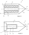
- a pipe pig 10 in accordance with an embodiment of the present invention is shown schematically in Figure 1 .
- the pipe pig 10 extends generally along a longitudinal axis 100 from a rear end 11 a to a front end 11b.
- directions that are parallel to the longitudinal axis 100 are referred to as axial
- directions radiating from the longitudinal axis 100 are referred to as radial
- directions around the longitudinal axis 100 are referred to as circumferential.
- the pipe pig 10 has a body 12 made of a deformable material and is generally cylindrical with a tapered front section 12a.
- the tapered front section 12a may be conical, as shown in the Figures.
- the tapered front section 12a may be frusto-conical or otherwise tapered.
- the pipe pig 10 is intended to travel along the bore of a pipe line in the forward (i.e. towards the front end 11b) direction.
- a tapered front section 12a may therefore facilitate passage of the pipe pig 10 in the bore in the event that any obstacles are present.
- the tapered front section 12a may include an attachment (not shown) such as a bar or loop that may facilitate the attachment of a tether.
- the tether may be used to pull the pipe pig 10 along the pipe bore (although, generally, the pipe pig 10 may be caused to move along the pipe bore due to the fluid pressure of the flowing fluid within the pipe), or to retrieve the pipe pig 10 from the pipe after use.
- the deformable material forming the body 12 may be foam.
- the foam may be an open cell foam such as polyurethane foam.
- the density of the deformable material may vary depending on the specific requirements (e.g. deformability) of the pipe pig 10.
- the pipe pig 10 includes a plurality of electromagnetic sensors 16 disposed about an outer surface of the body 12.
- the electromagnetic sensors 16 are disposed in groups on carriers 14 which support the electromagnetic sensors 16 and extend axially along the outer surface of the body 12.
- the electromagnetic sensors 16 may not be supported on a carrier 14 and may be supported directly on the body 12.
- the electromagnetic sensors 16 may be arranged on the body 12 in a helical arrangement relative to the longitudinal axis 100. In this sense, a helical arrangement is one that extends both axially and circumferentially about the longitudinal axis 100.
- the electromagnetic sensors 16 may be disposed within (e.g. embedded within) the material of body 12.
- the electromagnetic sensors 16 it is preferable for the electromagnetic sensors 16 to be arranged such that radial compression of the body 12 does not result in electromagnetic sensors 16 contacting one another. Such contact could lead to damage and limit the deformability of the pipe pig 10 and therefore reduce the maneuverability of the pipe pig 10 in a pipe.
- the outer surface of the body 12 may include one or more recesses for receiving the plurality of sensors 16.
- the recesses may receive the carriers 14.
- the recesses may serve to support the plurality of sensors 16 at a radial position that is radially inward relative to the remainder of the outer surface of the body 12. Such an arrangement may limit or prevent damage to the plurality of sensors 16 during travel of the pipe pig 10 along the pipe bore.
- the pipe pig 10 may include a coating that covers some or the entire outer surface of the body 12, where the coating may cover some or all of the plurality of sensors 16.
- the coating may comprise a polymeric material such as polyurethane, for example.
- the coating may be applied in any suitable manner including but not limited to painting, spraying, moulding, and adhering a formed layer to the body 12.
- the electromagnetic sensors 16 include means for inducing an electric current in a wall of a pipe as the pipe pig 10 travels through the bore of the pipe.
- the means for inducing an electric current in the pipe wall may include a generating coil that is energized to produce a magnetic field which, in turn, induces an electric current in the pipe wall.
- the magnetic field produced by the generating coil may be a time varying magnetic field (e.g. by energizing the generating coil with an AC current).
- the magnetic field may not be time varying and the movement of the generating coil (which is attached to the moveable pipe pig 10) relative to the pipe wall may cause the induction of an electric current in the pipe wall.
- the means for inducing an electric current in the pipe wall may include a magnet (e.g. a permanent magnet or electro-magnet) that moves (by virtue of the moving pipe pig 10) relative to the pipe wall to induce an electric current therein.
- a magnet e.g. a permanent magnet or electro-magnet
- the electromagnetic sensors 16 additionally include means for receiving an electromagnetic signal from the wall of the pipe, such that data about the pipe wall can be obtained as the pipe pig 10 travels along the bore of the pipe.
- the means for receiving an electromagnetic signal from the wall of the pipe include a receiving sensor.
- the receiving sensor may be a coil wherein a current is induced in the coil in response to an electromagnetic signal.
- the electromagnetic sensors 16 may be any sensors capable of performing eddy current testing.
- the electromagnetic sensors 16 may be provided as one or more printed circuit boards (PCBs) which may, in certain embodiments, be flexible.
- PCBs printed circuit boards
- each sensor may include a single generating coil and two receiving sensors.
- the body 12 can be seen to include an internal cavity 18.
- the internal cavity 18 has a rear part 18a and a forward part 18b where the rear part 18a has a greater diameter relative to the forward part 18b.
- the internal cavity 18 may contain one or more electronic components selected from but not limited to an electrical power source (which may be rechargeable) for supplying electrical power to the plurality of electromagnetic sensors 16, a memory for receiving data from the plurality of electromagnetic sensors 16, and a processor for processing data received from the plurality of electromagnetic sensors 16.
- the one or more electronic components may be housed within the cavity 18 in a housing 20 that serves to provide protection to the electronic components.
- the housing 20 may be pressure resistant so that the housing 20 maintains its integrity and continues to protect the electronic components in a pressurized environment within the pipe. In certain embodiments, the housing 20 may be capable of withstanding (e.g. remaining fluid tight) pressures up to 100 bar, 150 bar, 200 bar, 250 bar or 300 bar.
- the housing 20 is preferably made of a suitable material, and may, for example, comprise steel or stainless steel.
- the housing 20 may be removable from the body 12 such that the electronic components can be retrieved, interrogated (e.g. access and/or remove data from the memory), or replaced (e.g. if damaged) between uses of the pipe pig 10 in a pipe.
- the housing 20 may be reusable such that it can be interchanged between pipe pigs 10. This may be particularly useful if the pipe pig 10 has become damaged or worn and requires replacement, and allows the more costly components (contained within the housing 20) to be retrieved and reused.
- the electronic components may be electrically connected to the plurality of sensors 16 via one or more electrical connectors.
- the housing 20 may include an electrical connection through which electrical connections between the plurality of sensors 16 and the electronic components may be made.
- the rear part 18a of the cavity 18 may serve to protect some or all of the electrical connectors from damage as the pipe pig 10 travels within a pipe bore.
- the pipe pig 10 may be formed by moulding the body 12 and then attaching the plurality of sensors 16. Whilst in the above-described embodiments the plurality of sensors 16 are disposed about an outer surface of the body 12, in alternative embodiments, the plurality of sensors 16 may be disposed within the body 12. For example, the plurality of sensors 16 may be embedded within the body 12 by moulding the body 12 around the plurality of sensors 16.
- the plurality of sensors 16 may be supported on a carrier 14 that is provided for attachment to a pipe pig 10 in a desired arrangement.
- the pipe pig 10 is inserted into the bore of a pipe and travels along the pipe bore.
- the pressure of the fluid within the pipe e.g. oil
- the pipe pig 10 may serve to propel the pipe pig 10 along the pipe.
- the pipe pig 10 (or at least a part of it) preferably has a diameter that is comparable to the internal diameter of the pipe.
- the pipe pig 10 may be propelled by other means, e.g. pulled along the pipe by a tether.
- the plurality of sensors 16 induce electric currents in the wall of the pipe.
- the induced electric currents may be eddy currents, for example.
- the induced electric currents are then monitored by receiving electromagnetic signals from the wall of the pipe using the electromagnetic sensors 16. Variations in the electric currents (e.g. the phase and/or magnitude) may indicate the presence of flaws, defects, or irregularities in the pipe wall.
- the pipe pig 10 may therefore serve as an effective inspection tool that may provide an overview of the pipeline condition over the travel path. Areas of corrosion and cracking within the pipeline can therefore be identified. Additionally, since the body 12 of the pipe pig 10 is formed of a deformable material, the pipe pig 10 also has the benefits of a traditional utility pig, where it does not present a significant risk of becoming stuck in the pipe, and it may perform other operations such as the cleaning or drying of the pipeline.
- pipe pigs 10 in accordance with embodiments of the present invention may be capable of compressing to a diameter around 50% of an uncompressed state.
- the deformability of the body 12 may allow the pipe pig 10 to negotiate multi-diameter pipelines (e.g. variations between 18 inch (-46 cm) and 24 inch (-61 cm)).
- the body 12 may be formed of relatively inexpensive materials making the pipe pig 10 more economically attractive for frequent and widespread use.
- specialist launching and retrieving stations are not necessary for inserting and retrieving pipe pigs 10 accordingly to certain embodiments of the present invention thereby reducing the time, cost and logistical effort associated with using the pipe pigs 10 in contrast with prior art inspection pigs.
Landscapes
- Chemical & Material Sciences (AREA)
- Engineering & Computer Science (AREA)
- Physics & Mathematics (AREA)
- General Physics & Mathematics (AREA)
- General Engineering & Computer Science (AREA)
- Life Sciences & Earth Sciences (AREA)
- Chemical Kinetics & Catalysis (AREA)
- Biochemistry (AREA)
- General Health & Medical Sciences (AREA)
- Health & Medical Sciences (AREA)
- Immunology (AREA)
- Pathology (AREA)
- Analytical Chemistry (AREA)
- Electrochemistry (AREA)
- Combustion & Propulsion (AREA)
- Mechanical Engineering (AREA)
- Fluid Mechanics (AREA)
- Investigating Or Analyzing Materials By The Use Of Magnetic Means (AREA)
- Pipeline Systems (AREA)
- Cleaning In General (AREA)
Description
- The present invention relates to a pipe pig, and in particular, to a pipe pig for inspecting a pipeline.
- A pipe pig is a vessel that travels along the bore of a pipeline, such as an oil pipeline. Pipe pigs are often propelled along the pipeline by fluid (e.g. oil) flowing within the pipeline. So-called inspection pipe pigs often include sensors for collecting data about the pipeline as the pipe pig travels along the pipe and may be used to inspect the condition of the pipe walls.
- An example of a typical inspection pig is described in
US-A-2007022830 which makes use of magnetic flux sensors for collecting data. The sensors are mounted on moveable arms that extend from a rigid body, where the moveable arms ride against the internal profile of the pipeline as the inspection pig travels through the pipe. - Additionally, document
US-5398560 discloses an inspection pig for inspecting piping systems. The pig consists of a flexible, modular body containing a miniaturized eddy current inspection probe. The body is preferably made of flexible polyvinyl chloride (PVC) tubing or molded silicone rubber with a shrink wrapping of polytetrafluoroethylene. - Inspection pigs are often long, heavy and expensive pieces of apparatus that require a specialist launching station for inserting the pig into the pipeline and a specialist receiving station for retrieving the pig from the pipeline. As such, the preparation, travel and retrieval of an inspection pipe pig through a pipeline is an expensive, time-consuming and disruptive process. Furthermore, inspection pigs are known for being liable to get stuck within a pipeline and this often results in the pipeline being shutdown until the stuck inspection pig is removed. For certain pipelines (e.g. oil pipelines), any shutdown can be significantly costly. Inspection pigs are often sized for a specific diameter pipeline and have limited ability in negotiating bends in the pipeline or moving between areas of the pipeline with differing diameters. Therefore, a given inspection pig may only be used with pipelines having a suitable specification and multiple inspection pigs are required for inspection of wider ranges of pipelines.
- It is an object of certain embodiments of the present invention to provide an improved pipe pig that overcomes at least some of the disadvantages associated with the prior art.
- In accordance with an aspect of the present invention there is provided a pipe pig for travelling along the bore of a pipe, the pipe pig comprising:
- a body formed of a deformable material comprising foam; and
- a plurality of electromagnetic sensors disposed about an outer surface of the body or within the body;
- wherein the plurality of electromagnetic sensors include means for inducing an electric current in a wall of the pipe, and means for receiving an electromagnetic signal from the wall of the pipe, such that data about the pipe wall can be obtained as the pipe pig travels along a bore of the pipe.
- The means for inducing an electric current in the wall of the pipe may include a generating coil for producing a magnetic field.
- The generating coil may produce a time varying magnetic field.
- In certain embodiments, the means for inducing an electric current in the wall of the pipe may include a magnet, which may be a permanent magnet.
- The means for receiving an electromagnetic signal from the wall of the pipe may include a receiving sensor.
- The plurality of electromagnetic sensors may be disposed on one or more carriers that are disposed about the outer surface of the body. The outer surface of the body may include one or more recesses for receiving the one or more carriers. Multiple carriers may be provided where each carrier may be arranged on the outer surface of the body along a direction parallel to a longitudinal axis of the body, and wherein each carrier is circumferentially spaced from adjacent carriers. Alternatively, multiple carriers may be provided where each carrier may be arranged on the outer surface of the body along a direction that extends both axially and circumferentially relative to a longitudinal axis of the body.
- The body may include an internal cavity for containing one or more electronic components. In certain embodiments, the internal cavity may contain a housing for containing the one or more electronic components. The housing may be removable from the body. In certain embodiments, the housing may comprise a steel or stainless steel housing. In certain embodiments, the housing may be capable of withstanding pressures up to 100 bar, 150 bar, 200 bar, 250 bar or 300 bar.
- The one or more electronic components may include an electrical power source for supplying electrical power to the plurality of electromagnetic sensors. The electrical power source may be a rechargeable electrical power source.
- Additionally or alternatively, the one or more electronic components may include a memory for receiving data from the plurality of electromagnetic sensors.
- The pipe pig may further comprise a coating covering the plurality of electromagnetic sensors. The coating may provide a protective layer that may reduce the wear of the body or electromagnetic sensors and may comprise a polymeric material, such as polyurethane.
- The foam may be an open cell foam such as polyurethane foam. The density of the foam may vary depending on the specific requirements (e.g. deformability) of the pipe pig.
- Embodiments of the invention are further described hereinafter with reference to the accompanying drawings, in which:
-
Figure 1 is a schematic view of a pipe pig in accordance with an embodiment of the present invention; and -
Figure 2 is a schematic cross sectional view of the pipe pig ofFigure 1 . - A
pipe pig 10 in accordance with an embodiment of the present invention is shown schematically inFigure 1 . Thepipe pig 10 extends generally along alongitudinal axis 100 from a rear end 11 a to afront end 11b. Throughout the present specification, directions that are parallel to thelongitudinal axis 100 are referred to as axial, directions radiating from thelongitudinal axis 100 are referred to as radial, and directions around thelongitudinal axis 100 are referred to as circumferential. Thepipe pig 10 has abody 12 made of a deformable material and is generally cylindrical with atapered front section 12a. In certain embodiments, thetapered front section 12a may be conical, as shown in the Figures. In other embodiments, thetapered front section 12a may be frusto-conical or otherwise tapered. Thepipe pig 10 is intended to travel along the bore of a pipe line in the forward (i.e. towards thefront end 11b) direction. Atapered front section 12a may therefore facilitate passage of thepipe pig 10 in the bore in the event that any obstacles are present. In certain embodiments, thetapered front section 12a may include an attachment (not shown) such as a bar or loop that may facilitate the attachment of a tether. The tether may be used to pull thepipe pig 10 along the pipe bore (although, generally, thepipe pig 10 may be caused to move along the pipe bore due to the fluid pressure of the flowing fluid within the pipe), or to retrieve thepipe pig 10 from the pipe after use. - In certain embodiments, the deformable material forming the
body 12 may be foam. For example, the foam may be an open cell foam such as polyurethane foam. The density of the deformable material may vary depending on the specific requirements (e.g. deformability) of thepipe pig 10. - The
pipe pig 10 includes a plurality ofelectromagnetic sensors 16 disposed about an outer surface of thebody 12. In the non-limiting embodiment shown inFigure 1 , theelectromagnetic sensors 16 are disposed in groups oncarriers 14 which support theelectromagnetic sensors 16 and extend axially along the outer surface of thebody 12. In alternative embodiments, theelectromagnetic sensors 16 may not be supported on acarrier 14 and may be supported directly on thebody 12. Whether with or without acarrier 14, theelectromagnetic sensors 16 may be arranged on thebody 12 in a helical arrangement relative to thelongitudinal axis 100. In this sense, a helical arrangement is one that extends both axially and circumferentially about thelongitudinal axis 100. In certain embodiments, theelectromagnetic sensors 16 may be disposed within (e.g. embedded within) the material ofbody 12. In any embodiment, it is preferable for theelectromagnetic sensors 16 to be arranged such that radial compression of thebody 12 does not result inelectromagnetic sensors 16 contacting one another. Such contact could lead to damage and limit the deformability of thepipe pig 10 and therefore reduce the maneuverability of thepipe pig 10 in a pipe. - In certain embodiments, the outer surface of the
body 12 may include one or more recesses for receiving the plurality ofsensors 16. In particular, the recesses may receive thecarriers 14. In any embodiment where recesses are present, the recesses may serve to support the plurality ofsensors 16 at a radial position that is radially inward relative to the remainder of the outer surface of thebody 12. Such an arrangement may limit or prevent damage to the plurality ofsensors 16 during travel of thepipe pig 10 along the pipe bore. In further or alternative embodiments, thepipe pig 10 may include a coating that covers some or the entire outer surface of thebody 12, where the coating may cover some or all of the plurality ofsensors 16. The coating may comprise a polymeric material such as polyurethane, for example. The coating may be applied in any suitable manner including but not limited to painting, spraying, moulding, and adhering a formed layer to thebody 12. - The
electromagnetic sensors 16 include means for inducing an electric current in a wall of a pipe as thepipe pig 10 travels through the bore of the pipe. In certain embodiments, the means for inducing an electric current in the pipe wall may include a generating coil that is energized to produce a magnetic field which, in turn, induces an electric current in the pipe wall. The magnetic field produced by the generating coil may be a time varying magnetic field (e.g. by energizing the generating coil with an AC current). Alternatively, the magnetic field may not be time varying and the movement of the generating coil (which is attached to the moveable pipe pig 10) relative to the pipe wall may cause the induction of an electric current in the pipe wall. In further alternative embodiments, the means for inducing an electric current in the pipe wall may include a magnet (e.g. a permanent magnet or electro-magnet) that moves (by virtue of the moving pipe pig 10) relative to the pipe wall to induce an electric current therein. - The
electromagnetic sensors 16 additionally include means for receiving an electromagnetic signal from the wall of the pipe, such that data about the pipe wall can be obtained as thepipe pig 10 travels along the bore of the pipe. In certain embodiments, the means for receiving an electromagnetic signal from the wall of the pipe include a receiving sensor. For example, the receiving sensor may be a coil wherein a current is induced in the coil in response to an electromagnetic signal. In certain embodiments, theelectromagnetic sensors 16 may be any sensors capable of performing eddy current testing. - The
electromagnetic sensors 16 may be provided as one or more printed circuit boards (PCBs) which may, in certain embodiments, be flexible. In certain embodiments, each sensor may include a single generating coil and two receiving sensors. - In the cross-sectional view shown in
Figure 2 , thebody 12 can be seen to include aninternal cavity 18. In the non-limiting embodiment shown inFigure 2 , theinternal cavity 18 has arear part 18a and a forward part 18b where therear part 18a has a greater diameter relative to the forward part 18b. In use, theinternal cavity 18 may contain one or more electronic components selected from but not limited to an electrical power source (which may be rechargeable) for supplying electrical power to the plurality ofelectromagnetic sensors 16, a memory for receiving data from the plurality ofelectromagnetic sensors 16, and a processor for processing data received from the plurality ofelectromagnetic sensors 16. The one or more electronic components may be housed within thecavity 18 in ahousing 20 that serves to provide protection to the electronic components. Thehousing 20 may be pressure resistant so that thehousing 20 maintains its integrity and continues to protect the electronic components in a pressurized environment within the pipe. In certain embodiments, thehousing 20 may be capable of withstanding (e.g. remaining fluid tight) pressures up to 100 bar, 150 bar, 200 bar, 250 bar or 300 bar. Thehousing 20 is preferably made of a suitable material, and may, for example, comprise steel or stainless steel. Thehousing 20 may be removable from thebody 12 such that the electronic components can be retrieved, interrogated (e.g. access and/or remove data from the memory), or replaced (e.g. if damaged) between uses of thepipe pig 10 in a pipe. Thehousing 20 may be reusable such that it can be interchanged betweenpipe pigs 10. This may be particularly useful if thepipe pig 10 has become damaged or worn and requires replacement, and allows the more costly components (contained within the housing 20) to be retrieved and reused. - The electronic components may be electrically connected to the plurality of
sensors 16 via one or more electrical connectors. In certain embodiments, thehousing 20 may include an electrical connection through which electrical connections between the plurality ofsensors 16 and the electronic components may be made. Therear part 18a of thecavity 18 may serve to protect some or all of the electrical connectors from damage as thepipe pig 10 travels within a pipe bore. - In one example, the
pipe pig 10 may be formed by moulding thebody 12 and then attaching the plurality ofsensors 16. Whilst in the above-described embodiments the plurality ofsensors 16 are disposed about an outer surface of thebody 12, in alternative embodiments, the plurality ofsensors 16 may be disposed within thebody 12. For example, the plurality ofsensors 16 may be embedded within thebody 12 by moulding thebody 12 around the plurality ofsensors 16. - In one aspect of the invention, the plurality of
sensors 16 may be supported on acarrier 14 that is provided for attachment to apipe pig 10 in a desired arrangement. - In use, the
pipe pig 10 is inserted into the bore of a pipe and travels along the pipe bore. As noted above, the pressure of the fluid within the pipe (e.g. oil) may serve to propel thepipe pig 10 along the pipe. For thepipe pig 10 to be propelled by the fluid within the pipe, the pipe pig 10 (or at least a part of it) preferably has a diameter that is comparable to the internal diameter of the pipe. In other, less preferable embodiments, thepipe pig 10 may be propelled by other means, e.g. pulled along the pipe by a tether. During travel, the plurality ofsensors 16 induce electric currents in the wall of the pipe. The induced electric currents may be eddy currents, for example. The induced electric currents are then monitored by receiving electromagnetic signals from the wall of the pipe using theelectromagnetic sensors 16. Variations in the electric currents (e.g. the phase and/or magnitude) may indicate the presence of flaws, defects, or irregularities in the pipe wall. Thepipe pig 10 may therefore serve as an effective inspection tool that may provide an overview of the pipeline condition over the travel path. Areas of corrosion and cracking within the pipeline can therefore be identified. Additionally, since thebody 12 of thepipe pig 10 is formed of a deformable material, thepipe pig 10 also has the benefits of a traditional utility pig, where it does not present a significant risk of becoming stuck in the pipe, and it may perform other operations such as the cleaning or drying of the pipeline. For example,pipe pigs 10 in accordance with embodiments of the present invention may be capable of compressing to a diameter around 50% of an uncompressed state. The deformability of thebody 12 may allow thepipe pig 10 to negotiate multi-diameter pipelines (e.g. variations between 18 inch (-46 cm) and 24 inch (-61 cm)). Furthermore, thebody 12 may be formed of relatively inexpensive materials making thepipe pig 10 more economically attractive for frequent and widespread use. Additionally, specialist launching and retrieving stations are not necessary for inserting and retrievingpipe pigs 10 accordingly to certain embodiments of the present invention thereby reducing the time, cost and logistical effort associated with using thepipe pigs 10 in contrast with prior art inspection pigs. - Throughout the description and claims of this specification, the words "comprise" and "contain" and variations of them mean "including but not limited to", and they are not intended to (and do not) exclude other moieties, additives, components, integers or steps. Throughout the description and claims of this specification, the singular encompasses the plural unless the context otherwise requires. In particular, where the indefinite article is used, the specification is to be understood as contemplating plurality as well as singularity, unless the context requires otherwise.
- Features, integers, characteristics, compounds, chemical moieties or groups described in conjunction with a particular aspect, embodiment or example of the invention are to be understood to be applicable to any other aspect, embodiment or example described herein unless incompatible therewith. All of the features disclosed in this specification (including any accompanying claims, abstract and drawings), and/or all of the steps of any method or process so disclosed, may be combined in any combination, except combinations where at least some of such features and/or steps are mutually exclusive. The invention is not restricted to the details of any foregoing embodiments. The invention extends to any novel one, or any novel combination, of the features disclosed in this specification (including any accompanying claims, abstract and drawings), or to any novel one, or any novel combination, of the steps of any method or process so disclosed.
Claims (15)
- A pipe pig (10) for travelling along the bore of a pipe, the pipe pig (10) comprising:a body (12) formed of a deformable material comprising foam; anda plurality of electromagnetic sensors (16) disposed about an outer surface of the body (12) or within the body (12);wherein the plurality of electromagnetic sensors (16) include means for inducing an electric current in a wall of the pipe, and means for receiving an electromagnetic signal from the wall of the pipe, such that data about the pipe wall can be obtained as the pipe pig travels along a bore of the pipe.
- The pipe pig (10) of claim 1, wherein the means for inducing an electric current in the wall of the pipe include a generating coil for producing a magnetic field, wherein optionally the generating coil produces a time varying magnetic field.
- The pipe pig (10) of claim 1, wherein the means for inducing an electric current in the wall of the pipe include a magnet, wherein optionally the magnet is a permanent magnet.
- The pipe pig (10) of any preceding claim, wherein the means for receiving an electromagnetic signal from the wall of the pipe include a receiving sensor.
- The pipe pig (10) of any preceding claim, wherein the plurality of electromagnetic sensors (16) are disposed on one or more carriers (14) that are disposed about the outer surface of the body (12).
- The pipe pig (10) of claim 5, wherein the outer surface of the body (12) includes one or more recesses for receiving the one or more carriers (14).
- The pipe pig (10) of claim 5 or 6, wherein multiple carriers (14) are provided and each carrier (14) is arranged on the outer surface of the body (12) along a direction parallel to a longitudinal axis of the body (12), and wherein each carrier is circumferentially spaced from adjacent carriers.
- The pipe pig (10) of claim 5 or 6, wherein multiple carriers (14) are provided and each carrier (14) is arranged on the outer surface of the body (12) along a direction that extends both axially and circumferentially relative to a longitudinal axis of the body (12).
- The pipe pig (10) of any preceding claim, wherein the body (12) includes an internal cavity (18) for containing one or more electronic components.
- The pipe pig (10) of claim 9, wherein the internal cavity (18) contains a housing (20) for containing the one or more electronic components, wherein optionally the housing (20) is removable from the body (12).
- The pipe pig (10) of claim 10, wherein the housing (20) comprises a steel or stainless steel housing.
- The pipe pig (10) of any of claims 10 to 11, wherein the housing (20) is capable of withstanding pressures up to 100 bar, 150 bar, 200 bar, 250 bar or 300 bar.
- The pipe pig (10) of any of claims 9 to 12, wherein the one or more electronic components includes an electrical power source for supplying electrical power to the plurality of electromagnetic sensors (16), wherein optionally the electrical power source is a rechargeable electrical power source.
- The pipe pig (10) of any of claims 9 to 13, wherein the one or more electronic components includes a memory for receiving data from the plurality of electromagnetic sensors (16).
- The pipe pig (10) of any preceding claim, further comprising a coating covering the plurality of electromagnetic sensors (16), wherein optionally the coating comprises a polymeric material.
Applications Claiming Priority (2)
| Application Number | Priority Date | Filing Date | Title |
|---|---|---|---|
| GB1508570.7A GB2538517A (en) | 2015-05-19 | 2015-05-19 | Improved pipe pig |
| PCT/GB2016/051409 WO2016185193A1 (en) | 2015-05-19 | 2016-05-16 | Pipe pig for inspecting a pipeline |
Publications (2)
| Publication Number | Publication Date |
|---|---|
| EP3298396A1 EP3298396A1 (en) | 2018-03-28 |
| EP3298396B1 true EP3298396B1 (en) | 2020-04-22 |
Family
ID=53506004
Family Applications (1)
| Application Number | Title | Priority Date | Filing Date |
|---|---|---|---|
| EP16723493.9A Active EP3298396B1 (en) | 2015-05-19 | 2016-05-16 | Pipe pig for inspecting a pipeline |
Country Status (4)
| Country | Link |
|---|---|
| US (1) | US10444191B2 (en) |
| EP (1) | EP3298396B1 (en) |
| GB (1) | GB2538517A (en) |
| WO (1) | WO2016185193A1 (en) |
Families Citing this family (9)
| Publication number | Priority date | Publication date | Assignee | Title |
|---|---|---|---|---|
| US10401325B2 (en) | 2016-08-11 | 2019-09-03 | Novitech, Inc. | Magnetizers for pigging tools |
| US10769684B1 (en) * | 2017-10-03 | 2020-09-08 | Wells Fargo Bank, N.A. | Property assessment system with buoyancy adjust device |
| GB2572809B (en) | 2018-04-12 | 2020-11-11 | Subsea 7 Ltd | Internal inspection of pipelines |
| CN110645881A (en) * | 2019-09-30 | 2020-01-03 | 卓爱忠 | Pipe inner wall walking device for measuring roughness of long pipe and working method thereof |
| US11280440B2 (en) * | 2020-01-07 | 2022-03-22 | Tdw Delaware, Inc. | Re-settable pipeline gauging tool with deformable body |
| CN111375607B (en) * | 2020-04-14 | 2025-08-01 | 中国石油大学(北京) | Pipeline inspection pig with multi-layer foam |
| MX2023015240A (en) * | 2022-12-22 | 2024-06-24 | Petroleo Brasileiro Sa Petrobras | Method and tool for inspecting the condition of the internal surface of pipes. |
| US12523633B2 (en) | 2024-02-06 | 2026-01-13 | Novitech Inc. | Magnetizers for pigging tools having rotational elements |
| US20250389367A1 (en) * | 2024-06-25 | 2025-12-25 | Saudi Arabian Oil Company | Pipeline scale removal |
Family Cites Families (13)
| Publication number | Priority date | Publication date | Assignee | Title |
|---|---|---|---|---|
| US5398560A (en) * | 1993-07-12 | 1995-03-21 | The United States Of America As Represented By The United States Department Of Energy | Apparatus for inspecting piping |
| JP3578959B2 (en) * | 2000-02-24 | 2004-10-20 | 松下電器産業株式会社 | Table tap and monitoring system using the table tap |
| NO314701B3 (en) * | 2001-03-20 | 2007-10-08 | Reslink As | Flow control device for throttling flowing fluids in a well |
| US7138897B2 (en) * | 2003-10-15 | 2006-11-21 | Schlumberger Technology Corporation | Induction measurements with reduced borehole effects |
| GB2408340A (en) * | 2003-11-18 | 2005-05-25 | Radiodetection Ltd | A vehicle for inspecting a pipe |
| US6847207B1 (en) * | 2004-04-15 | 2005-01-25 | Tdw Delaware, Inc. | ID-OD discrimination sensor concept for a magnetic flux leakage inspection tool |
| GB0428127D0 (en) | 2004-12-22 | 2005-01-26 | Pll Ltd | A sensor system for an in-line inspection tool |
| US7256576B2 (en) * | 2005-07-29 | 2007-08-14 | General Electric Company | ID-OD discrimination sensor |
| US7265649B1 (en) * | 2007-02-19 | 2007-09-04 | Hall David R | Flexible inductive resistivity device |
| US7598742B2 (en) * | 2007-04-27 | 2009-10-06 | Snyder Jr Harold L | Externally guided and directed field induction resistivity tool |
| GB2475736B (en) * | 2009-11-30 | 2013-10-30 | Pipeline Innovations Ltd | Improved instrumented foam pig |
| JP2014052296A (en) * | 2011-09-09 | 2014-03-20 | Gs Yuasa Corp | Monitoring device |
| US8937279B2 (en) * | 2011-12-08 | 2015-01-20 | Saudi Arabian Oil Company | Super-resolution formation fluid imaging with contrast fluids |
-
2015
- 2015-05-19 GB GB1508570.7A patent/GB2538517A/en not_active Withdrawn
-
2016
- 2016-05-16 WO PCT/GB2016/051409 patent/WO2016185193A1/en not_active Ceased
- 2016-05-16 US US15/575,471 patent/US10444191B2/en active Active
- 2016-05-16 EP EP16723493.9A patent/EP3298396B1/en active Active
Non-Patent Citations (1)
| Title |
|---|
| None * |
Also Published As
| Publication number | Publication date |
|---|---|
| GB201508570D0 (en) | 2015-07-01 |
| EP3298396A1 (en) | 2018-03-28 |
| US10444191B2 (en) | 2019-10-15 |
| US20180172638A1 (en) | 2018-06-21 |
| WO2016185193A1 (en) | 2016-11-24 |
| GB2538517A (en) | 2016-11-23 |
Similar Documents
| Publication | Publication Date | Title |
|---|---|---|
| US10444191B2 (en) | Pipe pig for inspecting a pipeline | |
| US10801994B2 (en) | Pipe pig | |
| US5461313A (en) | Method of detecting cracks by measuring eddy current decay rate | |
| EP0905497B1 (en) | Device for inspection of water pipelines and method | |
| US8089273B2 (en) | Spiral magnetic field apparatus and method for pipeline inspection | |
| US10578583B2 (en) | Systems, apparatus, and methods for inspecting submerged surfaces | |
| AU2014363465A1 (en) | Connection end-piece of a flexible pipe, associated device and method | |
| US6198277B1 (en) | Sensor module for use in system for inspecting in-service gas distribution mains | |
| WO2016162683A1 (en) | In-line inspection tool | |
| EP2249355A2 (en) | Magnetising assembly | |
| WO2013192536A1 (en) | System and method for subsea inspection | |
| US12338938B2 (en) | Operating a pipeline inspection gauge | |
| MY191140A (en) | Hoses and detecting failures in reinforced hoses | |
| US20210285914A1 (en) | Method and apparatus for electromagnetic testing of pipes | |
| EP0855548A2 (en) | Evacuating pipelines and apparatus therefor | |
| KR101644861B1 (en) | Removing apparatus of scale for pipe line | |
| JP6984876B2 (en) | Transport pipes with wear detection function, transport pipe manufacturing method, wear detection method, and transport pipe operation method | |
| KR101750045B1 (en) | The Method for tracking pig using pressure and flow rate of sending fluid | |
| US20250052718A1 (en) | Circumferential magnetizer for a pipeline inspection gauge | |
| KR20150052382A (en) | Apparatus for communicating inspection robot of undersea pipe | |
| EP2098846B1 (en) | System and process for detecting leakage in umbilicals | |
| AU2017329037B2 (en) | Electric field expansion system for low voltage conductivity inspection | |
| RU101520U1 (en) | INSERT ELECTRIC INSULATING PIPELINE | |
| Kosasih et al. | Low Cost-Low Risk Intelligent Pig: Sharing Experience of Running Eddy Current Pig for Subsea Pipeline Inspection | |
| ITMI20112450A1 (en) | APPARATUS AND METHOD TO MONITOR THE STRUCTURAL INTEGRITY OF A CONDUCT |
Legal Events
| Date | Code | Title | Description |
|---|---|---|---|
| STAA | Information on the status of an ep patent application or granted ep patent |
Free format text: STATUS: THE INTERNATIONAL PUBLICATION HAS BEEN MADE |
|
| PUAI | Public reference made under article 153(3) epc to a published international application that has entered the european phase |
Free format text: ORIGINAL CODE: 0009012 |
|
| STAA | Information on the status of an ep patent application or granted ep patent |
Free format text: STATUS: REQUEST FOR EXAMINATION WAS MADE |
|
| 17P | Request for examination filed |
Effective date: 20171214 |
|
| AK | Designated contracting states |
Kind code of ref document: A1 Designated state(s): AL AT BE BG CH CY CZ DE DK EE ES FI FR GB GR HR HU IE IS IT LI LT LU LV MC MK MT NL NO PL PT RO RS SE SI SK SM TR |
|
| AX | Request for extension of the european patent |
Extension state: BA ME |
|
| DAV | Request for validation of the european patent (deleted) | ||
| DAX | Request for extension of the european patent (deleted) | ||
| GRAP | Despatch of communication of intention to grant a patent |
Free format text: ORIGINAL CODE: EPIDOSNIGR1 |
|
| STAA | Information on the status of an ep patent application or granted ep patent |
Free format text: STATUS: GRANT OF PATENT IS INTENDED |
|
| INTG | Intention to grant announced |
Effective date: 20190708 |
|
| GRAS | Grant fee paid |
Free format text: ORIGINAL CODE: EPIDOSNIGR3 |
|
| GRAA | (expected) grant |
Free format text: ORIGINAL CODE: 0009210 |
|
| STAA | Information on the status of an ep patent application or granted ep patent |
Free format text: STATUS: THE PATENT HAS BEEN GRANTED |
|
| AK | Designated contracting states |
Kind code of ref document: B1 Designated state(s): AL AT BE BG CH CY CZ DE DK EE ES FI FR GB GR HR HU IE IS IT LI LT LU LV MC MK MT NL NO PL PT RO RS SE SI SK SM TR |
|
| REG | Reference to a national code |
Ref country code: CH Ref legal event code: EP |
|
| REG | Reference to a national code |
Ref country code: DE Ref legal event code: R096 Ref document number: 602016034527 Country of ref document: DE |
|
| REG | Reference to a national code |
Ref country code: IE Ref legal event code: FG4D |
|
| REG | Reference to a national code |
Ref country code: AT Ref legal event code: REF Ref document number: 1260797 Country of ref document: AT Kind code of ref document: T Effective date: 20200515 |
|
| REG | Reference to a national code |
Ref country code: NL Ref legal event code: FP |
|
| REG | Reference to a national code |
Ref country code: LT Ref legal event code: MG4D |
|
| PG25 | Lapsed in a contracting state [announced via postgrant information from national office to epo] |
Ref country code: LT Free format text: LAPSE BECAUSE OF FAILURE TO SUBMIT A TRANSLATION OF THE DESCRIPTION OR TO PAY THE FEE WITHIN THE PRESCRIBED TIME-LIMIT Effective date: 20200422 Ref country code: PT Free format text: LAPSE BECAUSE OF FAILURE TO SUBMIT A TRANSLATION OF THE DESCRIPTION OR TO PAY THE FEE WITHIN THE PRESCRIBED TIME-LIMIT Effective date: 20200824 Ref country code: SE Free format text: LAPSE BECAUSE OF FAILURE TO SUBMIT A TRANSLATION OF THE DESCRIPTION OR TO PAY THE FEE WITHIN THE PRESCRIBED TIME-LIMIT Effective date: 20200422 Ref country code: FI Free format text: LAPSE BECAUSE OF FAILURE TO SUBMIT A TRANSLATION OF THE DESCRIPTION OR TO PAY THE FEE WITHIN THE PRESCRIBED TIME-LIMIT Effective date: 20200422 Ref country code: IS Free format text: LAPSE BECAUSE OF FAILURE TO SUBMIT A TRANSLATION OF THE DESCRIPTION OR TO PAY THE FEE WITHIN THE PRESCRIBED TIME-LIMIT Effective date: 20200822 Ref country code: GR Free format text: LAPSE BECAUSE OF FAILURE TO SUBMIT A TRANSLATION OF THE DESCRIPTION OR TO PAY THE FEE WITHIN THE PRESCRIBED TIME-LIMIT Effective date: 20200723 Ref country code: NO Free format text: LAPSE BECAUSE OF FAILURE TO SUBMIT A TRANSLATION OF THE DESCRIPTION OR TO PAY THE FEE WITHIN THE PRESCRIBED TIME-LIMIT Effective date: 20200722 |
|
| REG | Reference to a national code |
Ref country code: AT Ref legal event code: MK05 Ref document number: 1260797 Country of ref document: AT Kind code of ref document: T Effective date: 20200422 |
|
| PG25 | Lapsed in a contracting state [announced via postgrant information from national office to epo] |
Ref country code: LV Free format text: LAPSE BECAUSE OF FAILURE TO SUBMIT A TRANSLATION OF THE DESCRIPTION OR TO PAY THE FEE WITHIN THE PRESCRIBED TIME-LIMIT Effective date: 20200422 Ref country code: RS Free format text: LAPSE BECAUSE OF FAILURE TO SUBMIT A TRANSLATION OF THE DESCRIPTION OR TO PAY THE FEE WITHIN THE PRESCRIBED TIME-LIMIT Effective date: 20200422 Ref country code: BG Free format text: LAPSE BECAUSE OF FAILURE TO SUBMIT A TRANSLATION OF THE DESCRIPTION OR TO PAY THE FEE WITHIN THE PRESCRIBED TIME-LIMIT Effective date: 20200722 Ref country code: HR Free format text: LAPSE BECAUSE OF FAILURE TO SUBMIT A TRANSLATION OF THE DESCRIPTION OR TO PAY THE FEE WITHIN THE PRESCRIBED TIME-LIMIT Effective date: 20200422 |
|
| PG25 | Lapsed in a contracting state [announced via postgrant information from national office to epo] |
Ref country code: AL Free format text: LAPSE BECAUSE OF FAILURE TO SUBMIT A TRANSLATION OF THE DESCRIPTION OR TO PAY THE FEE WITHIN THE PRESCRIBED TIME-LIMIT Effective date: 20200422 |
|
| REG | Reference to a national code |
Ref country code: DE Ref legal event code: R097 Ref document number: 602016034527 Country of ref document: DE |
|
| PG25 | Lapsed in a contracting state [announced via postgrant information from national office to epo] |
Ref country code: CZ Free format text: LAPSE BECAUSE OF FAILURE TO SUBMIT A TRANSLATION OF THE DESCRIPTION OR TO PAY THE FEE WITHIN THE PRESCRIBED TIME-LIMIT Effective date: 20200422 Ref country code: RO Free format text: LAPSE BECAUSE OF FAILURE TO SUBMIT A TRANSLATION OF THE DESCRIPTION OR TO PAY THE FEE WITHIN THE PRESCRIBED TIME-LIMIT Effective date: 20200422 Ref country code: CH Free format text: LAPSE BECAUSE OF NON-PAYMENT OF DUE FEES Effective date: 20200531 Ref country code: IT Free format text: LAPSE BECAUSE OF FAILURE TO SUBMIT A TRANSLATION OF THE DESCRIPTION OR TO PAY THE FEE WITHIN THE PRESCRIBED TIME-LIMIT Effective date: 20200422 Ref country code: SM Free format text: LAPSE BECAUSE OF FAILURE TO SUBMIT A TRANSLATION OF THE DESCRIPTION OR TO PAY THE FEE WITHIN THE PRESCRIBED TIME-LIMIT Effective date: 20200422 Ref country code: LI Free format text: LAPSE BECAUSE OF NON-PAYMENT OF DUE FEES Effective date: 20200531 Ref country code: AT Free format text: LAPSE BECAUSE OF FAILURE TO SUBMIT A TRANSLATION OF THE DESCRIPTION OR TO PAY THE FEE WITHIN THE PRESCRIBED TIME-LIMIT Effective date: 20200422 Ref country code: EE Free format text: LAPSE BECAUSE OF FAILURE TO SUBMIT A TRANSLATION OF THE DESCRIPTION OR TO PAY THE FEE WITHIN THE PRESCRIBED TIME-LIMIT Effective date: 20200422 Ref country code: DK Free format text: LAPSE BECAUSE OF FAILURE TO SUBMIT A TRANSLATION OF THE DESCRIPTION OR TO PAY THE FEE WITHIN THE PRESCRIBED TIME-LIMIT Effective date: 20200422 Ref country code: MC Free format text: LAPSE BECAUSE OF FAILURE TO SUBMIT A TRANSLATION OF THE DESCRIPTION OR TO PAY THE FEE WITHIN THE PRESCRIBED TIME-LIMIT Effective date: 20200422 Ref country code: ES Free format text: LAPSE BECAUSE OF FAILURE TO SUBMIT A TRANSLATION OF THE DESCRIPTION OR TO PAY THE FEE WITHIN THE PRESCRIBED TIME-LIMIT Effective date: 20200422 |
|
| PG25 | Lapsed in a contracting state [announced via postgrant information from national office to epo] |
Ref country code: SK Free format text: LAPSE BECAUSE OF FAILURE TO SUBMIT A TRANSLATION OF THE DESCRIPTION OR TO PAY THE FEE WITHIN THE PRESCRIBED TIME-LIMIT Effective date: 20200422 Ref country code: PL Free format text: LAPSE BECAUSE OF FAILURE TO SUBMIT A TRANSLATION OF THE DESCRIPTION OR TO PAY THE FEE WITHIN THE PRESCRIBED TIME-LIMIT Effective date: 20200422 |
|
| PLBE | No opposition filed within time limit |
Free format text: ORIGINAL CODE: 0009261 |
|
| STAA | Information on the status of an ep patent application or granted ep patent |
Free format text: STATUS: NO OPPOSITION FILED WITHIN TIME LIMIT |
|
| REG | Reference to a national code |
Ref country code: BE Ref legal event code: MM Effective date: 20200531 |
|
| 26N | No opposition filed |
Effective date: 20210125 |
|
| PG25 | Lapsed in a contracting state [announced via postgrant information from national office to epo] |
Ref country code: LU Free format text: LAPSE BECAUSE OF NON-PAYMENT OF DUE FEES Effective date: 20200516 |
|
| PG25 | Lapsed in a contracting state [announced via postgrant information from national office to epo] |
Ref country code: FR Free format text: LAPSE BECAUSE OF NON-PAYMENT OF DUE FEES Effective date: 20200622 Ref country code: IE Free format text: LAPSE BECAUSE OF NON-PAYMENT OF DUE FEES Effective date: 20200516 |
|
| PG25 | Lapsed in a contracting state [announced via postgrant information from national office to epo] |
Ref country code: BE Free format text: LAPSE BECAUSE OF NON-PAYMENT OF DUE FEES Effective date: 20200531 Ref country code: SI Free format text: LAPSE BECAUSE OF FAILURE TO SUBMIT A TRANSLATION OF THE DESCRIPTION OR TO PAY THE FEE WITHIN THE PRESCRIBED TIME-LIMIT Effective date: 20200422 |
|
| PG25 | Lapsed in a contracting state [announced via postgrant information from national office to epo] |
Ref country code: TR Free format text: LAPSE BECAUSE OF FAILURE TO SUBMIT A TRANSLATION OF THE DESCRIPTION OR TO PAY THE FEE WITHIN THE PRESCRIBED TIME-LIMIT Effective date: 20200422 Ref country code: MT Free format text: LAPSE BECAUSE OF FAILURE TO SUBMIT A TRANSLATION OF THE DESCRIPTION OR TO PAY THE FEE WITHIN THE PRESCRIBED TIME-LIMIT Effective date: 20200422 Ref country code: CY Free format text: LAPSE BECAUSE OF FAILURE TO SUBMIT A TRANSLATION OF THE DESCRIPTION OR TO PAY THE FEE WITHIN THE PRESCRIBED TIME-LIMIT Effective date: 20200422 |
|
| PG25 | Lapsed in a contracting state [announced via postgrant information from national office to epo] |
Ref country code: MK Free format text: LAPSE BECAUSE OF FAILURE TO SUBMIT A TRANSLATION OF THE DESCRIPTION OR TO PAY THE FEE WITHIN THE PRESCRIBED TIME-LIMIT Effective date: 20200422 |
|
| PGFP | Annual fee paid to national office [announced via postgrant information from national office to epo] |
Ref country code: NL Payment date: 20250519 Year of fee payment: 10 |
|
| PGFP | Annual fee paid to national office [announced via postgrant information from national office to epo] |
Ref country code: DE Payment date: 20250514 Year of fee payment: 10 |
|
| PGFP | Annual fee paid to national office [announced via postgrant information from national office to epo] |
Ref country code: GB Payment date: 20260331 Year of fee payment: 11 |