EP3298300B1 - Method for controlling a damper device - Google Patents
Method for controlling a damper device Download PDFInfo
- Publication number
- EP3298300B1 EP3298300B1 EP16727965.2A EP16727965A EP3298300B1 EP 3298300 B1 EP3298300 B1 EP 3298300B1 EP 16727965 A EP16727965 A EP 16727965A EP 3298300 B1 EP3298300 B1 EP 3298300B1
- Authority
- EP
- European Patent Office
- Prior art keywords
- data set
- damper
- measurement data
- damping
- control
- Prior art date
- Legal status (The legal status is an assumption and is not a legal conclusion. Google has not performed a legal analysis and makes no representation as to the accuracy of the status listed.)
- Active
Links
- 238000000034 method Methods 0.000 title claims description 31
- 238000005259 measurement Methods 0.000 claims description 116
- 238000013016 damping Methods 0.000 claims description 106
- 230000001133 acceleration Effects 0.000 claims description 64
- 238000001914 filtration Methods 0.000 claims description 53
- 230000033001 locomotion Effects 0.000 claims description 45
- 230000005291 magnetic effect Effects 0.000 claims description 45
- 238000009499 grossing Methods 0.000 claims description 17
- 239000012530 fluid Substances 0.000 claims description 13
- 238000006073 displacement reaction Methods 0.000 claims description 6
- 230000035939 shock Effects 0.000 description 20
- 238000012545 processing Methods 0.000 description 11
- 230000006870 function Effects 0.000 description 10
- 239000004020 conductor Substances 0.000 description 9
- 238000012935 Averaging Methods 0.000 description 8
- 239000006096 absorbing agent Substances 0.000 description 8
- 238000011161 development Methods 0.000 description 8
- 230000018109 developmental process Effects 0.000 description 8
- 230000004044 response Effects 0.000 description 8
- 230000008859 change Effects 0.000 description 7
- 238000007906 compression Methods 0.000 description 7
- 230000008901 benefit Effects 0.000 description 6
- 238000006243 chemical reaction Methods 0.000 description 6
- 230000006835 compression Effects 0.000 description 6
- 239000000463 material Substances 0.000 description 4
- 239000000725 suspension Substances 0.000 description 4
- 239000012212 insulator Substances 0.000 description 3
- 230000000737 periodic effect Effects 0.000 description 3
- 238000007790 scraping Methods 0.000 description 3
- 238000001514 detection method Methods 0.000 description 2
- 238000010586 diagram Methods 0.000 description 2
- 230000035622 drinking Effects 0.000 description 2
- 238000011156 evaluation Methods 0.000 description 2
- 239000003302 ferromagnetic material Substances 0.000 description 2
- 230000006872 improvement Effects 0.000 description 2
- 239000000696 magnetic material Substances 0.000 description 2
- 230000005415 magnetization Effects 0.000 description 2
- 239000000615 nonconductor Substances 0.000 description 2
- 238000002360 preparation method Methods 0.000 description 2
- 230000008569 process Effects 0.000 description 2
- 238000006748 scratching Methods 0.000 description 2
- 230000002393 scratching effect Effects 0.000 description 2
- 230000007704 transition Effects 0.000 description 2
- JQUCWIWWWKZNCS-LESHARBVSA-N C(C1=CC=CC=C1)(=O)NC=1SC[C@H]2[C@@](N1)(CO[C@H](C2)C)C=2SC=C(N2)NC(=O)C2=NC=C(C=C2)OC(F)F Chemical compound C(C1=CC=CC=C1)(=O)NC=1SC[C@H]2[C@@](N1)(CO[C@H](C2)C)C=2SC=C(N2)NC(=O)C2=NC=C(C=C2)OC(F)F JQUCWIWWWKZNCS-LESHARBVSA-N 0.000 description 1
- 238000010521 absorption reaction Methods 0.000 description 1
- 230000006978 adaptation Effects 0.000 description 1
- 230000032683 aging Effects 0.000 description 1
- 230000009286 beneficial effect Effects 0.000 description 1
- 230000005540 biological transmission Effects 0.000 description 1
- 230000000903 blocking effect Effects 0.000 description 1
- 238000004364 calculation method Methods 0.000 description 1
- 244000145845 chattering Species 0.000 description 1
- 238000005352 clarification Methods 0.000 description 1
- 239000011248 coating agent Substances 0.000 description 1
- 238000000576 coating method Methods 0.000 description 1
- 238000004891 communication Methods 0.000 description 1
- 239000002131 composite material Substances 0.000 description 1
- 230000001351 cycling effect Effects 0.000 description 1
- 230000006378 damage Effects 0.000 description 1
- 230000001419 dependent effect Effects 0.000 description 1
- 238000013461 design Methods 0.000 description 1
- 230000000694 effects Effects 0.000 description 1
- 230000005294 ferromagnetic effect Effects 0.000 description 1
- 239000000835 fiber Substances 0.000 description 1
- 239000000945 filler Substances 0.000 description 1
- 239000000203 mixture Substances 0.000 description 1
- 239000012811 non-conductive material Substances 0.000 description 1
- 238000010606 normalization Methods 0.000 description 1
- 230000001151 other effect Effects 0.000 description 1
- 230000002085 persistent effect Effects 0.000 description 1
- 230000000704 physical effect Effects 0.000 description 1
- 230000036632 reaction speed Effects 0.000 description 1
- 230000009467 reduction Effects 0.000 description 1
- 230000003252 repetitive effect Effects 0.000 description 1
- 230000000284 resting effect Effects 0.000 description 1
- 230000035807 sensation Effects 0.000 description 1
- 239000004575 stone Substances 0.000 description 1
- 238000005728 strengthening Methods 0.000 description 1
- 238000004804 winding Methods 0.000 description 1
Images


Classifications
-
- F—MECHANICAL ENGINEERING; LIGHTING; HEATING; WEAPONS; BLASTING
- F16—ENGINEERING ELEMENTS AND UNITS; GENERAL MEASURES FOR PRODUCING AND MAINTAINING EFFECTIVE FUNCTIONING OF MACHINES OR INSTALLATIONS; THERMAL INSULATION IN GENERAL
- F16F—SPRINGS; SHOCK-ABSORBERS; MEANS FOR DAMPING VIBRATION
- F16F15/00—Suppression of vibrations in systems; Means or arrangements for avoiding or reducing out-of-balance forces, e.g. due to motion
- F16F15/002—Suppression of vibrations in systems; Means or arrangements for avoiding or reducing out-of-balance forces, e.g. due to motion characterised by the control method or circuitry
-
- F—MECHANICAL ENGINEERING; LIGHTING; HEATING; WEAPONS; BLASTING
- F16—ENGINEERING ELEMENTS AND UNITS; GENERAL MEASURES FOR PRODUCING AND MAINTAINING EFFECTIVE FUNCTIONING OF MACHINES OR INSTALLATIONS; THERMAL INSULATION IN GENERAL
- F16F—SPRINGS; SHOCK-ABSORBERS; MEANS FOR DAMPING VIBRATION
- F16F9/00—Springs, vibration-dampers, shock-absorbers, or similarly-constructed movement-dampers using a fluid or the equivalent as damping medium
- F16F9/32—Details
- F16F9/3292—Sensor arrangements
-
- F—MECHANICAL ENGINEERING; LIGHTING; HEATING; WEAPONS; BLASTING
- F16—ENGINEERING ELEMENTS AND UNITS; GENERAL MEASURES FOR PRODUCING AND MAINTAINING EFFECTIVE FUNCTIONING OF MACHINES OR INSTALLATIONS; THERMAL INSULATION IN GENERAL
- F16F—SPRINGS; SHOCK-ABSORBERS; MEANS FOR DAMPING VIBRATION
- F16F9/00—Springs, vibration-dampers, shock-absorbers, or similarly-constructed movement-dampers using a fluid or the equivalent as damping medium
- F16F9/32—Details
- F16F9/53—Means for adjusting damping characteristics by varying fluid viscosity, e.g. electromagnetically
- F16F9/535—Magnetorheological [MR] fluid dampers
Definitions
- the present invention relates to a method for controlling a damper device.
- the damper device has two connection units that can be moved relative to one another, between which at least one controllable damper is provided for damping relative movements, the damper having at least one first damper chamber and at least one associated damping valve.
- the damping valve has a damping channel with a magnetorheological fluid.
- a magnetic field generating device is assigned to the damping valve and is used to generate and control a magnetic field. A type of opening state of the damping valve is thus influenced.
- Damping in the form of vibrations and/or shocks has a major impact on e.g. B. the driving characteristics of vehicles and is therefore an important feature, especially in sporty vehicles.
- the use of a damper enables improved ground contact and allows sporty driving even on winding roads.
- Magnetorheological dampers on the wheels that switch in milliseconds enable comfortable and safe operation.
- the steering column or in seat belts for energy absorption in accidents allow such magnetorheological dampers optimal adaptation to the accident scenario and thus the least possible injuries to the occupants.
- the damping device comprises a controllable damping valve with a field generating device, with which a field-sensitive medium such as a magnetorheological fluid can be influenced in order to influence the damping force of the damping device by applying a field strength of the field generating device .
- the damping force of the damper device is adjusted in real time.
- the damper is not set to a specific type of road, but adapts to the current condition at any time. For this purpose, events in the form of impacts are recognized and a relative speed of the damper ends is periodically recorded.
- a characteristic value is derived in real time from the relative speed and, in turn, a field strength to be set is derived from a damping characteristic curve using the characteristic value.
- the field strength to be set is generated in real time with the field generating device in order to immediately and automatically set the damping force.
- the well-known damper device works very reliably and switches within a few milliseconds and much faster than the prior art, so that the damper device z. B. when cycling while driving over a root or a stone is continuously adapted to the currently prevailing conditions. For example, when driving on a slippery road surface, the damper remains set hard so that drive energy is not unnecessarily dissipated in the damper device. In principle, the damper device works very satisfactorily. However, it turned out that in In some situations, for example when the shock absorber on a bicycle is slowly compressed manually, the shock absorber does not compress softly, which the shock absorber should allow at a low compression speed, but gives a scratchy or scraping feedback to the user's hand.
- the measurement data was filtered, but this led to a considerable time delay in the reaction of the damping device, which was disadvantageous in terms of driving dynamics or performance, as a result of which shocks were cushioned too late and large shocks were not cushioned in good time. This all takes place in the range of microseconds.
- the measuring frequency was increased in order to obtain the correct reaction of the damping device at all times and thus a smoother transition in all areas due to a faster sequence of the measured values. But even increasing the measurement frequency did not bring any improvement in compression and rebound behavior. And that despite the fact that the damping device can be fully adjusted within a few milliseconds.
- the method according to the invention serves to control the damping of a relative movement of two connection units that can be moved relative to one another, between which at least one controllable damper with a damping valve with a magneto-rheological medium, fluid or damping fluid is provided for damping the relative movements.
- At least one magnetic field generating device for generating and controlling a magnetic field is assigned to the at least one damping valve.
- Measurement data records are recorded at least via a relative movement of the connection units to one another and processed with a filter device.
- a derived data set includes in particular (a value for) a speed signal and (a value for) an acceleration signal for a relative movement of the connection units.
- At least one data set derived from a recorded measurement data set is stored in the memory device.
- At least one stored data set is analyzed and a set of filter parameters is determined depending on the result of the analysis.
- a filter parameter set with stronger filtering is selected and in the case of speed signals that are larger in magnitude or acceleration signals that are larger in terms of magnitude, a filter parameter set with less filtering is selected.
- a control data set is derived from the measurement data set with the filter parameter set. The control device uses the control data set to control the damper device at least partially and in particular also completely.
- the method according to the invention offers many advantages, since it performs processing that is adapted as a function of the analysis of the measurement data, as a result of which suitable damping parameters can be set at any time.
- the method according to the invention is carried out with a damping device which comprises two connection units which can be moved relative to one another, between which, in order to dampen relative movements such as e.g. B. shocks or vibrations at least one controllable damper is provided with a magnetorheological medium, fluid or damping fluid.
- the damper has at least one first damper chamber and at least one damping valve connected thereto.
- At least one magnetic field generating device is assigned to the at least one damping valve, which is used to generate and control a magnetic field in at least one damping channel of the damping valve.
- the or at least one magnetorheological fluid is at least partially provided in the damping channel.
- At least one control device and at least one memory device are also provided.
- At least one sensor device is provided for acquiring measurement data sets at least via a relative movement of the connection units to one another.
- a plurality of data sets can preferably be stored in the memory device.
- a filter device is provided for processing the measurement data records.
- At least one data record derived from a measurement data record recorded with the sensor device during the relative movement of the connection units that can be moved relative to one another can be stored in the memory device.
- the measurement data set and/or the derived data set includes at least one speed signal and/or at least one acceleration signal for the movement of the connection units relative to one another.
- An analysis device is provided, which is designed and set up to analyze at least one stored data set and to determine a filter parameter set depending on the result of the analysis.
- the control device for this formed, in terms of absolute value low speed signals and acceleration signals, a filter parameter set with stronger filtering and, in the case of speed signals or acceleration signals that are larger in absolute value, a filter parameter set with less filtering.
- the control device is designed to use the filter parameter set to derive a control data set from the measurement data set, so that the control device uses the control data set to control the damper device at least partially or completely.
- Controlling the damper device using the method according to the invention has many advantages.
- a significant advantage of controlling the damper device is that the analysis device analyzes the recorded measurement data sets, so that a filter parameter set is determined depending on the result of the analysis, with which a control data set is derived from the measurement data set, with which the damping valve of the magnetorheological damper is at least partially controlled.
- a suitable set of filter parameters is determined by analyzing the measurement datasets of the relative movement of the connection units that can be moved relative to one another, in order to ensure a rapid response behavior of the damper device that is sufficiently soft in all situations.
- the term data set is understood to mean a data set with at least one value or measured value contained therein. It is also possible and preferred that a data set contains several different values or parameters.
- a measurement data set can contain distance information and speed information as well as acceleration information and the like. However, it is also possible for a measurement data set to contain only a single measured value. The same also applies to a derived data set that is stored in the storage device and also to a control data set that is determined from the stored data set and/or the measurement data set.
- a filter parameter set may contain one or more filter parameters.
- a set of parameters preferably includes several parameters. However, it is also possible for a parameter set to contain only one parameter.
- a derived data record that is stored in the memory device is also referred to below as a “stored data record”.
- the derived and stored data set can be identical to the associated measurement data set or is obtained from it through processing. For example, a normalization can be carried out.
- control device is designed and set up to analyze at least one stored data set and, depending on the result of the analysis, to determine a filter parameter set from a plurality of filter parameter sets and to derive a control data set from the measurement data set using the determined filter parameter set.
- the filter device filters measurement data less intensively when there is a more intensive movement of the connection units relative to one another.
- a more intensive relative movement is understood to mean a faster relative movement or a faster acceleration relative to one another or possibly also an absolute speed or acceleration.
- the filtering is more intensive. This means that the measurement data or the value or values of a measurement data set are denoised to a greater extent. This can provide a smoother timing.
- the control device controls the damper device directly or indirectly using further components such as (power) electronics and in particular using a magnetic field generating device. In any case, the damping of the damping device is adjusted with the control data record.
- Prepared data records are obtained from the measurement data records by preparation and/or by pre-filtering and/or by filtering, which preferably form the basis for further processing be placed.
- the measurement of the measurement data records is preferably carried out with a frequency that is greater than 200 Hz or 500 Hz and in particular greater than 1 kHz.
- Both the current measurement data set and at least one previous measurement data set or at least the current derived data set and/or at least one previously derived data set can be stored in the memory device. It is also possible and preferred that the respectively current control data set is stored in the memory device.
- a preset filter parameter set is preferably loaded and at least one first measurement data set is recorded.
- a control data set with the preset filter parameter set is derived from the measurement data set.
- a new or current measurement data record is then recorded in a loop.
- a filter parameter set is then selected or derived from the preceding control data set.
- a current control data set is derived with the filter parameter set determined in this way. The damping of the damper device is adjusted taking into account this control data set or with this control data set.
- the measurement data set that was still current becomes the previous measurement data set.
- the current measurement data record is recorded.
- a filter parameter set is selected via the control data set of a preceding loop and in particular the last loop, and a current control data set is derived with the current measurement data set and the selected filter parameter set, with the aid of which the damping is then adjusted.
- a current measurement data record is also initially recorded.
- a filter parameter set is selected via the current measurement data set and a current control data set is derived from the current measurement data set using the selected filter parameter set.
- the damping is then set taking into account the current control data record.
- the filter parameter set can possibly also be determined iteratively.
- a new partial loop run is carried out to determine the filter parameter set if the currently determined control data set deviates from the previous control data set by a certain amount or if the control data set or the values contained therein fall below or exceed certain limits.
- a current measurement data set is first recorded and a current control data set is derived from the current measurement data set using the previous filter parameter set.
- the control data set is then used to check whether the correct filter parameter set was selected.
- the filter parameter set is possibly reselected and a new control data set or current control data set is derived again.
- a check can also be carried out here as to whether the correct filter parameter set has been selected.
- This iteration loop can be repeated any number of times. Preferably, the iteration loop is limited in number to avoid a persistent loop. Finally, the damping is set with the current control data record.
- a plurality of filter parameter sets are stored in the storage device and a filter parameter set can be selected as a function of the at least one stored data set.
- the stored data record can be the measurement data record as it is recorded. But it is also possible that with the sensor device the recorded measurement data set is processed in a first processing step in order to obtain, for example, standardized values and then to store the data set determined in this way in the storage device.
- a plurality of data sets that have been measured and processed together are preferably stored in the storage device. Depending on the storage capacity, a FIFO method can be selected so that a number of the most recent measurement data sets remain in the storage device.
- the analysis device comprises a comparison device and the comparison device compares a stored data set with comparison data and, depending on the result of the comparison, selects a filter parameter set stored in the memory device or derives a filter parameter set and derives a control data set from the measurement data set with the filter parameter set .
- a set of filter parameters can preferably be selected as a function of the at least one stored data record. This means that a filter parameter set can be selected depending on the content of at least one stored data record. Accordingly, the content of a stored data record can be compared with comparison data using the comparison device.
- a plurality of data sets can be stored in the memory device.
- this also includes the data records derived from them and stored in the memory device, as well as the control data records that can be stored in the memory device and possibly the like.
- the sensor device is particularly preferably designed to detect at least one displacement signal.
- the control device is designed to derive a speed signal for a relative movement of the connection units from a sensor signal (in particular that of the sensor device).
- a computing unit is provided, which can be part of the control device.
- the control device is preferably designed to derive an acceleration signal from a sensor signal (in particular that of the sensor device).
- the control device is designed and set up to derive an acceleration signal of the required quality from a sensor signal.
- the control device determines the acceleration signal from the sensor signal at a frequency of preferably greater than 1 kHz.
- a computing unit which can also be part of the control device, is preferably also provided for calculating the acceleration signal. The same computing unit can be used to calculate the acceleration signal and the speed signal.
- the damper device is controlled in particular in real time. This means that a damping is set at any time that is necessary and sensible for the current load situation.
- the damper device is not set to a suitable “average value”, but the sensor device is read out at any time (periodically at 1 kHz or more) and speed signals and/or acceleration signals are recorded and derived in particular from displacement signals.
- a suitable damping for the current speed signal is now set in real time at any point in time, since the damping device can be freely adjusted in a few milliseconds.
- the unclaimed control device is designed to select a filter parameter set with stronger filtering in the case of speed signals and acceleration signals that are low in terms of absolute value.
- the control device is preferably designed to select a filter parameter set with less filtering in the case of speed signals or acceleration signals that are larger in terms of absolute value. That means a Filter parameter set with stronger filtering is selected when the velocity signal and the acceleration signal are small. A filter parameter set with less filtering is selected even if only one of the two signals, namely the speed signal and the acceleration signal, is larger. This ensures a very fast response to bumps, while smoothing out more with low signals. However, this prevents a (too) late reaction to a strong impact.
- Such chattering has been found to occur particularly when the speed signal is below 10% and more likely below 5% of the maximum speed signal typical of operation.
- the maximum occurring speed signal z. B. is about 0.5 m / s or 1 m / s
- a "scratch" can occur in particular with speed signals of up to 0.05 or 0.02 m / s.
- speed signals below a predetermined limit are filtered more intensively, so that noise is removed more intensively.
- the speed signals are higher, there is less filtering or no filtering at all.
- the speed signal is filtered less intensively, even if the absolute value is small. This combination achieves an optimal result.
- the sensor device is advantageously suitable and designed to detect the displacement signal with a resolution of better than 100 ⁇ m.
- the resolution of the path signal can also be better than 50 ⁇ m or better than 30 ⁇ m and preferably better than 10 ⁇ m be.
- the chassis can be controlled very precisely.
- the sensor device is suitable and designed to acquire the sensor signal with a measurement frequency of at least 500 Hz or at least 1 kHz.
- the measuring frequency can also reach or exceed 5 kHz.
- the damper comprises at least one second damper chamber in addition to the first damper chamber.
- the first damper chamber and the second damper chamber are coupled to one another via at least one damping valve or one controllable damping valve in particular.
- the at least one damping valve or at least one damping valve is assigned at least one magnetic field generating device, which is used to generate and control a magnetic field in at least one damping channel of the damping valve.
- At least one magnetorheological fluid or medium in general is particularly preferably provided in the damping channel. By means of a magnetorheological medium in the damping channel, at least one property of the damping device can be set individually and quickly by controlling the magnetic field generating device. The damping force of the damper or damper device can be completely readjusted within a few milliseconds.
- At least one speed signal or speed data is derived from the measurement data set.
- at least one acceleration signal or acceleration data can be derived from the measurement data set.
- a measurement data record or at least one value of a measurement data record is filtered more intensively when the absolute value of the respective value of the measurement data record is smaller than when the magnitude of the value or values of the measurement dataset is greater. Threshold values or a set of limit values can be provided to differentiate whether stronger or weaker filtering is carried out.
- the values of the measurement data set can contain path values, acceleration values and/or speed values. Filtering can also be understood as smoothing the values.
- amount of values means the mathematical amount - i.e. unsigned.
- the relative movement is filtered more strongly at low speeds than at high speeds.
- the speed signal is taken into account in order to decide whether filtering is stronger or weaker.
- the relative movement is filtered more strongly in the case of low accelerations or acceleration signals than in the case of high accelerations or high acceleration signals.
- stronger filtering is understood here to mean more intensive filtering. This means that more heavily filtered measurement data are denoised more intensively. This can be done, for example, by considering a larger number of previous measurement data or by considering previous measurement data with a higher weighting. More filtering results in more smoothing than less filtering. This leads to a lower cut-off frequency. Edges become more rounded with stronger filtering than with weaker filtering, where the cutoff frequency is higher. Stronger filtering leads in particular to stronger denoising than weaker filtering. Velocity signals and acceleration signals are particularly preferably taken into account in order to decide how strong the filtering is. When the speed signal exceeds a predetermined speed limit or when the acceleration signal exceeds a predetermined acceleration limit exceeds, the filtering is weaker than if the speed signal and the acceleration signal are smaller than the respective limit.
- the measurement frequency must be high enough to allow a sufficiently quick reaction to all events to be expected at any time. So must a damping device when a shock occurs when z. E.g. driving over a bumper, a pothole, a root or a jump so quickly react and choose the right one Make damper settings that optimal or at least adequate damping properties are present.
- z. B. in motor vehicles according to the prior art today regularly not, since there no shock is damped in real time or can be damped due to the "slow" damper, but at most the general damper setting is changed.
- the damper setting of the damper device is adjusted many times during an impact in order to have optimal damper settings in each case.
- the measuring frequency and the controller frequency of the control device must therefore be correspondingly high in order to implement the concept with high dynamics.
- At least a plurality of data sets recorded one after the other are stored in the memory device.
- Measurements is output as a measurement data record.
- Such "oversampling” can be carried out both on the hardware and software side. It is important that the output rate of the measurement datasets is fast enough.
- a strength or intensity of the smoothing preferably depends on the stored data set.
- strengthening the smoothing depends on the current dataset.
- the number of data sets used for the averaging is varied. Will, for example, stronger filtering desired, the smoothing can be carried out over a correspondingly larger number of data sets recorded one after the other, while with weaker filtering a correspondingly smaller number of data sets is taken into account for the averaging.
- the proportional factors for sliding averaging are varied as a function of the strength of the desired filtering.
- neighboring or previous measured values can be taken into account with the same weighting or a similar weighting as the current measured value.
- the current measured value and the previous 4 values (10 values) can each be taken into account at 20% (10%) for stronger filtering.
- weaker filtering on the other hand, (fewer measured values and) measured values that are further apart in time can be taken into account with a lower proportional factor.
- the current measured value can be taken into account with 75% and the previous measured value with 25%. Or the current measured value and the one before it are each taken into account with 50%, while with stronger filtering the current measured value and the two measured values before that are each taken into account with the same weighting (33%).
- IIR filters Infinite Impulse Response
- FIR filters Finite Impulse Response
- Kalman filter is also preferred, in which case at least one parameter of the Kalman filter is then varied with the strength of the filtering.
- the sensor device records measurement data sets with a measurement frequency greater than 250 Hz (in particular 500 Hz and preferably 1 kHz) and/or that the control device records control data sets with a control frequency greater than 250 Hz (in particular 500 Hz and preferably 1 kHz) determined.
- the damper device is at least temporarily with at least this Control frequency of 250 Hz (particularly 500 Hz and preferably 1 kHz) driven.
- the measuring frequency and the control frequency are particularly preferably >2 kHz.
- the measurement frequency and/or the control frequency are preferably greater than 5 kHz.
- the sensor device particularly preferably detects path signals with a resolution of less than 100 ⁇ m or less than 50 ⁇ m. A resolution of less than 30 ⁇ m and particularly preferably less than 10 ⁇ m is preferably achieved. This allows high-resolution relative movements to be determined, which increases accuracy.
- the measuring frequency and the control frequency are at least temporarily greater than 8 kHz and the resolution of the displacement signals is at least temporarily less than 10 ⁇ m or 5 ⁇ m.
- the measurement frequency is less than 50 kHz and preferably less than 20 kHz or if measurement data sets are output at a frequency of less than 50 kHz and preferably less than 20 kHz.
- the measurement frequency and the control frequency are different.
- the measurement frequency is preferably greater than the control frequency.
- the control frequency is preferably greater than 50 Hz and in particular greater than 100 Hz and preferably greater than 250 Hz or greater than 500 Hz.
- the measuring frequency is in particular greater than 250 Hz and preferably greater than 500 Hz and particularly preferably greater than 1 kHz.
- a ratio of measurement frequency to control frequency can be greater than 2 and in particular greater than 4 and preferably greater than 8 or 16.
- the invention makes available an advantageous method and an advantageous damper device, with which an adapted and respectively smooth response behavior is made possible in all load ranges.
- the recording of measured values was not too slow before, but rather too fast at low damper speeds, since also due to the noise that inevitably occurs, which is at least partly also caused by digitization effects, with increasing measuring frequency at low rates of change of the measured variables, the relative errors increase, which is why the damper set the noisy values too quickly due to its high reaction speed.
- the measured values change from one step to the next at such a speed that the digitization does not introduce any significant errors.
- an unclaimed damper device comprises two connection units that can be moved relative to one another, between which, for damping relative movements such as e.g. B. shocks or vibrations at least one controllable magnetorheological damper is provided.
- At least one control device and at least one memory device are provided.
- At least one sensor device is provided for acquiring measurement data sets at least via a relative movement of the connection units to one another.
- a filter device is provided for processing the measurement data records. At least one data record derived from a measurement data record recorded with the sensor device during the relative movement of the connection units that can be moved relative to one another can be stored in the memory device.
- An analysis device is provided, which is designed and set up to analyze at least one stored data set and, depending on the result of the analysis, to determine a filter parameter set and to derive a control data set from the measurement data set using the filter parameter set, so that the control device uses the control data set to control the damper device at least partially or fully controlled. Developments contain some or all of the features of the damper device described above.
- An increase in measurement accuracy has also proven advantageous and/or the measurement resolution.
- a coordinated adjustment of measurement resolution and measurement frequency and filtering of the measurement data after analysis of the measurement data are particularly advantageous.
- the evaluation takes place in real time.
- the filter device it is preferably possible for the filter device to be integrated into the control device.
- the filtering can be carried out at least partially or completely by a computing unit of the control device.
- damping device 100 is used on a bicycle 200 here.
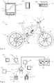
- FIG. 1 shows a schematic representation of a bicycle 200, which is designed here as a mountain bike and has a frame 113 and a front wheel 111 and a rear wheel 112. Both the front wheel 111 and the rear wheel 112 are equipped with spokes and can have the disc brakes shown. A gear shift is used to select the gear ratio. Furthermore, the bicycle 200 has a steering device 116 with a handlebar and a saddle 117 .
- the front wheel 111 has a damper device 100 designed as a spring fork 114 and a damper device 100 designed as a rear wheel damper 115 is provided on the rear wheel 112 .
- the damper device 100 comprises a damper 1 and a control device 46. It is also possible for the damper device 100 to comprise two dampers 1 (spring fork and rear wheel shock absorber), on each of which a control device 46 is provided. Or the damper device 100 comprises two dampers 1 and a (central) control device 60. The (central) control device 60 can be used to set the specifications and to coordinate the two dampers.
- the central control device 60 is provided here together with a battery unit 61 in a drinking bottle-like container and is arranged on the down tube where a drinking bottle is otherwise arranged, but can also be provided in the frame.
- the central control device 60 can also be arranged on the handlebar 116 .
- the damper 1 and other bicycle components can be controlled as a function of a wide variety of parameters and is also essentially based on data recorded by sensors. In particular, aging of the damping medium, the spring device and other components can also be taken into account. It is also preferable to consider the temperature of the damper device 100 or the damper 1 (spring fork 114 and/or rear wheel shock absorber 115).
- the damper device 100 and its central control device 60 are operated via operating devices 150 .
- Two operating devices 150 are provided, namely an operating device 151 and an adjusting device 152.
- the operating device 151 has mechanical input units 153 at the lateral ends or in the vicinity of the lateral ends of the handlebar 116.
- the adjustment device 152 can be designed as a bicycle computer and can have a touch-sensitive screen and can also be positioned on the handlebar 116 .
- a smartphone 160 or a tablet or the like to be used as the setting device 152 and to be kept in the user's pocket or backpack, for example, if the settings are not changed.
- the display 49 is designed in particular as a graphical control unit or touchscreen 57 so that the user can touch a displayed characteristic damper curve 10 with his fingers and change it by dragging.
- damper characteristic curve 50 which is also shown, can be generated from damper characteristic curve 10, which is shown as a solid line, and is then used immediately for the control.
- the damper characteristics 10, 50 can also be changed while driving.
- the setting device 152 can also serve as a bicycle computer and display information about the current speed, as well as the average speed and/or the daily, tour, lap and total kilometers. It is also possible to display the current position, the current altitude of the route driven and the route profile and also a possible range under the current attenuation conditions.
- FIG 2 shows a schematic representation of the control of the damper device 100 and the communication connections of some components involved.
- the central control device 60 can be wired or wirelessly connected to the individual components.
- the control device 60 (or 46) can be connected to the other components via WLAN, Bluetooth, ANT+, GPRS, UMTS, LTE or other transmission standards. If necessary, the control device 60 can be wirelessly connected to the Internet 53 via the connection shown in dotted lines.
- the control devices 46 and/or 60 are connected to at least one sensor device 20 or to a plurality of sensors.
- the control device 60 is connected via network interfaces 54 or radio network interfaces 55 to control devices 46 of the dampers 1 on the front wheel and on the rear wheel.
- the control device 46 possibly provided on each damper 1 ensures local control and can each have a battery or be connected to the central battery unit 61 . It is preferred that both dampers are controlled via the control device 60 . Local control of the dampers 1 via an associated control device 46 is also possible.
- At least one sensor device 20 is preferably assigned to each damper 1 in order to detect relative movements between the components or connection units 101 and 102 . In particular, a relative position of the components 101 and 102 relative to one another can be determined.
- the sensor device 20 is preferably designed as a (relative) travel sensor or comprises at least one such and is integrated into the damper 100 .
- the use of at least one additional acceleration sensor 47 is also possible and preferred.
- the sensor device 20 can also preferably be designed as a speed sensor or include such a sensor.
- a suitable spring force can be determined via the weight of the driver.
- the weight of the driver can be derived by automatically determining the compression position (sag) after a driver touches down.
- a suitable air pressure in the fluid spring or gas spring can be deduced from the deflection travel when the rider places himself on the bicycle, which is then automatically set or approximated immediately or in the course of operation.
- control circuit 12 is shown schematically, which is stored in the memory device 45 and stored in the control device 46 or 60 or programmed. The control circuit 12 is carried out periodically and in particular continuously periodically during operation.
- a current relative movement or relative speed of the first component or connection unit 101 to the second component or connection unit 102 is detected with the sensor device 20 .
- a characteristic value is derived from the values of the sensor device 20, which is representative of the current relative speed. A relative speed is preferably used as the characteristic value.
- the (cf. 3 ) Damper 1 has a first and a second damper chamber, between which a damping valve 8 is arranged.
- the damping valve 8 has at least one damping channel 7 which is exposed to a magnetic field of an electric coil device in order to influence the magneto-rheological medium or fluid (MRF) in the damping channel 7 and thus set the desired damping force.
- MRF magneto-rheological medium or fluid
- step 56 the associated damping force to be set is then derived from the current measured values, taking into account the predetermined or selected damper characteristic.
- a measure for the current field strength or current strength to be set is derived from this, with which the damping force to be set is at least approximately achieved.
- the measure can be the field strength itself or z.
- the current field strength to be set is generated or the corresponding current strength is applied to the electrical coil device 11 as the field generation device, so that within a single cycle or a time period of the control circuit 12, the damping force is generated which, with the selected or predetermined damping characteristic for the current relative speed of the first connection unit 101 to the second connection unit 102 is provided.
- the next cycle then starts and step 52 is carried out again.
- each cycle takes less than 30 ms and in particular less than 20 ms. It is possible that the acquisition of the sensor data and the subsequent calculations are carried out at a higher speed (e.g. a particularly integer multiple of the measurement frequency).
- FIG 3 shows an embodiment of a damper device 100 with a damper 1 and here with a spring device 42, which is designed as an air spring and includes a positive chamber 43 and a negative chamber 44.
- the damper 1 is fastened with the first end as a component 101 and the second end as a component 102 on different parts of a support device 120 (here on a vehicle) in order to dampen relative movements.
- the damper 1 comprises a first damper chamber 3 and a second damper chamber 4, which are separated from one another by the damping valve 8 designed as a piston 5.
- an external damper valve 8 is also possible, which is arranged outside of the damper housing 2 and is connected via corresponding supply lines.
- the piston 5 is connected to a piston rod 6 .
- the magnetorheological damping valve 8 shown in dashed lines which here comprises an electric coil 11 as a field generating device in order to generate a corresponding field strength.
- the damping valve 8 or the "open state" of the damping valve is on the electrical coil device 11 driven.
- the coil of the electrical coil device 11 is not wound around the piston rod 6 in the circumferential direction, but rather around an axis which extends transversely to the longitudinal extent of the piston rod 6 (and here parallel to the plane of the drawing).
- a relative movement takes place linearly here and takes place in the direction of movement 18.
- the magnetic field lines run in the central area of the core approximately perpendicularly to the longitudinal extension of the piston rod 6 and thus pass through the damping channels 7 approximately perpendicularly.
- a damping channel is located behind the plane of the drawing and is drawn in with dashed lines.
- a compensating piston 72 is arranged in the damper housing 2 and separates a compensating chamber 71 for the volume of the piston rod entering during compression.
- a gas or gas mixture is preferably located in the compensation space 71 .
- the damper device 100 has a sensor device 20 .
- the sensor device 20 comprises a detector head 21 and a structured scale device 30.
- the scale device 30 here comprises a sensor tape with permanent magnet units as field generation units.
- the poles of the permanent magnet units alternate, so that north-south poles are arranged in alternation along the direction of movement of the detector 22 .
- the magnetic field strength is evaluated by the detector head and the current position 19 is determined from this.
- the structure and the function of the sensor device 20 are explained in more detail below.
- the sensor device 20 is arranged within a housing of the damper device 1 or is radially surrounded by a housing 2 or 76 of the damper device on at least one longitudinal section. This means that the sensor device 20 is arranged at least in sections within the outer circumference of the spring housing 76 and/or within the outer circumference of the damper housing 2 .
- the spring device 42 here extends at least partially around the damper housing 2 and includes a spring housing 76.
- One end of the damper 1 is connected to a suspension piston 37 or forms one.
- the suspension piston 37 separates the positive chamber 43 from a negative chamber 44.
- the damper housing 2 with the first damper chamber 3 dips into the spring housing 76 or is surrounded by it.
- the spring housing 76 also at least partially surrounds the second damping chamber.
- the spring housing 76 is closed off at the end of the connection unit 101 by a cover 77 .
- the connecting cable 38 for the electrical coil device 11 is also brought out there.
- An electrical connection cable for the sensor device 20 is preferably also routed to the outside there.
- the sensor device 20 comprises two sensor parts, namely the detector head 21, which is arranged within the positive chamber 43 of the spring device 42 in the variant shown here above.
- the sensor device 20 comprises the scale device 30 as a further sensor part, which is arranged or accommodated in the spring housing 76 in this variant.
- the scale device 30 can be integrated into the wall of the spring housing 76 or arranged on the inner wall of the spring housing 76 .
- the scale device 30 in a longitudinal groove to be used on the outer wall of the spring housing 76. This is e.g. This is possible, for example, if the sensor device is based on the evaluation of magnetic field strengths or uses magnetic field strengths and if the spring housing 76 consists, for example, of a fiber composite material or of another magnetically non-conductive material.
- the scale device 30 is integrated into the piston rod, for example.
- the scale device 30 can, for. B. in a groove of the piston rod 6 can be used.
- the piston rod 6 preferably consists of a magnetically non-conductive or poorly conductive material.
- the detector head 21 comprises two detectors 22 and 23, which are arranged offset to one another in the direction of movement 18 here.
- the detector head 21 is arranged on the spring piston 37 and in particular fastened thereto.
- the detector head 21 is located radially further outwardly adjacent (but spaced) from the scale means 30 in the spring housing 76.
- the detector head 21 is arranged radially further inwardly on the spring piston 37.
- the scale device 30 has a structure 32 that extends over a measurement section 31 and over which the physical properties of the scale device 30 change periodically.
- the scale device 30 has sensor sections 33 (cf Figures 4 to 7 ) are arranged, each of which has repetitive electrical and/or magnetic properties and thus form the structure 32 of the scale device 30 .
- the scale device 30 has a multiplicity of permanent magnets, the poles of which are arranged alternately, so that a north pole and a south pole alternate in alternation.
- the detector head 21 is equipped with detectors 22 and 23 which detect a magnetic field.
- the detectors 22 and 23 can be embodied as electrical coils or, for example, as Hall sensors in order to detect the intensity of a magnetic field of the permanent magnets.
- connection units 101 and 102 of the damper 1 now move relative to each other, the position 19 of the damper 1 changes and the relative position of the detector head 21 shifts relative to the scale device 30.
- at least two detectors 22, 23 can thus be used to draw conclusions about the relative position of the detector head 21 relative to a sensor section 33 or relative to the scale device 30 or the absolute position within a sensor section 33. If two detectors are offset from one another in the direction of movement 18 and both detectors detect the magnetic field of the scale device 30, the position 19 and the direction of movement 18 can be determined very precisely by evaluating the signals.
- the number of sensor sections or periods passed is stored in the memory device 45 of the control device 46, so that the absolute position 19 can be deduced. All that is required for this is that the measuring frequency is so high that a complete sensor section is not pushed past “unnoticed” during a measuring cycle.
- the resolution of the sensor device 20 can be significantly increased. It is possible that the resolution for determining the position 19 is smaller by a factor of 50, 100, 500, 1000, 2000, 4000 or more than a length 34 of a sensor section 33. Factors that are a power of 2 are particularly preferably used e.g. 128, 256, 512, 1024, 2048, 4096, 8192, 16384 or more. This facilitates the (digital) signal processing. As a result, when using a structure 32 with sensor sections 33 in the millimeter range, a resolution in the micrometer range can be achieved.
- the sensor device 20 can comprise permanent magnets as field generation units 35 on the scale device 30, as is shown in figure 4 is shown. However, it is also possible that the structure 30 does not generate a permanent magnetic field, but that other physical and in particular magnetic and/or electrical properties change over the length of the structure 32 .
- the scale device 30 can be formed at least partially from a ferromagnetic material, with the scale device 30 having prongs, teeth, projections, grooves or other structures on the ferromagnetic material, for example at regular or predetermined intervals, which can serve to determine a position. It is also possible for the scale device to consist entirely of an insulator or non-conductor 67, for example, in which conductors 66 are embedded at periodic intervals.
- Various measuring principles of the sensor device 20 are described below with reference to the Figures 4 to 7 explained.
- FIG 4 A variant of the sensor device 20 is shown, in which the structure 30 has permanent magnets as field generation units 35 .
- the poles of the field generation units 35 are preferably arranged alternately, so that a periodically changing magnetic field results over the measuring section 31 of the scale device 30 .
- the detector head 21 is arranged inside the housing 76 and the scale device 30 is integrated into the damper housing 2 or spring housing 76 or another housing.
- Position marks 39 or the like are provided at certain intervals in order to provide certain calibration points for calibrating the absolute position or to enable an absolute position determination via certain codes. In all cases, separate end position sensors can also be provided.
- the scale device 30 can be composed of individual permanent magnets or can be designed as an individual magnet with alternating magnetization.
- Preferred as Scale device 30 uses a magnetic tape, for example made of plastic-bonded magnetic material.
- the scale device 30 can in particular be part of the housing 2 or 76 or another part of the damper 1 if this consists at least in part of a material with hard-magnetic properties.
- the relative, in certain versions also absolute, position determination can take place through locally different magnetization of the material.
- a preferred embodiment provides for the scale device 30 to be applied to the housing 2 or 76 etc. in the form of a hard-magnetic coating. Layer thicknesses of less than 1 millimeter or less than 100 micrometers and in particular less than 10 micrometers can be achieved and are sufficient for position determination.
- figure 5 shows a variant in which permanent magnets 35 are also arranged at regular intervals on the scale device 30 .
- a non-magnetic material is provided between the permanent magnets 35, for example. This also results in a periodically changing intensity of the magnetic field over the measuring section 31 of the scale device 30.
- a detector head 21 with here also two detectors 22, 23 is drawn in very schematically, with the detection angle for the two detectors being drawn in to make it clear that with this detectors 22, 23, which are offset in the direction of movement 18, different intensities result during the measurement.
- figure 6 shows another configuration of the sensor device 20, the structured scale device 30 being embodied ferromagnetically, for example, and providing no or essentially no magnetic field of its own.
- the outer shape of the ferromagnetic part of the scale device 30 is provided with a regular structure, tips 65 or teeth or other projections or recesses being provided at regular and/or predetermined intervals.
- the length 34 of a sensor section 33 results here from the distance between two Points 65 or spikes or the like.
- the space between the tips 65 can be filled with a filling compound 64 .
- the detector head 21 preferably again comprises two magnetic field sensors or detectors 22 and 23.
- a magnetic field generating device 26 is provided in the form of a permanent magnet, for example.
- the magnetic field of the magnetic field generating device 26 is influenced or "bent" by the structure 32 of the scale device 30, so that here too, depending on the position of the individual detectors 22 and 23, different field strengths of the magnetic field of the magnetic field generating device 26 result, which are generated by the detectors 22, 23 are detected.
- the detectors 22, 23 can be designed, for example, as electrical coils or Hall sensors or the like.
- the structure 32 of the scale device 30 does not necessarily have to have the same lengths 34 of the sensor sections 33 over its entire length. It is also possible that some of the sensor sections 33 have shorter (or longer) sensor sections in a section 63 , for example. It is also possible for each individual sensor section 33 to have a different length. Different lengths of the sensor sections 33 can be useful, for example, in order to automatically bring about a higher resolution in the vicinity of an end point. Conversely, a greater distance or a greater length of a sensor section 33 can be provided in other areas in order to make the sensor device 20 less sensitive there.
- a preferred embodiment provides for the scale device 30 to be designed in such a way that two or more parallel paths run in the direction of movement 18 and act like individual scales. Individual scales do not have to act uniformly over the entire length of the movement, for example when used as an index at the ends.
- the detector head 30 is then designed accordingly and has at least one additional detector 22 .
- the position of the detector head 30 can also be determined absolutely by using two or more tracks in the scale device 30: either by digital coding or two tracks with different lengths of the respective sensor sections 33, similar to the nonius in calipers.
- FIG 7 shows another embodiment of a sensor device 20 in which the scale device 30 has no magnetic parts here.
- the scale device 30 again has a structure 32, with conductors 66 being inserted here at periodic intervals in a material which is intrinsically non-conductive or an insulator or non-conductor 67.
- a length 34 of a sensor section 33 is determined by the distance between two conductors 66 .
- the detector head 21 has a magnetic field generating device 26 which is designed to provide an alternating magnetic field. Furthermore, the detector head has at least one detector and in particular at least two detectors 22, 23, which in turn serve to detect magnetic fields or the intensity of magnetic fields.
- the magnetic field generating device 26 generates a particularly high-frequency alternating magnetic field.
- eddy currents are generated in the conductors 66, which in turn induce magnetic fields in the conductors 66 which are directed opposite to the exciting magnetic field.
- the magnetic field is displaced from the conductors 66 and amplified between the conductors 66, so that in the illustration according to figure 7 detector 23 receives a stronger signal than detector 22.
- detector head 21 is further displaced relative to scale device 30, the magnetic conditions change as a function of position, so that position 19 can be derived from the signals from detectors 22, 23.
- the direction of movement 18 can also be inferred.
- the measured values determined by means of the sensor device 20 are figure 8 Process shown prepared to control at least one damper 1 with it.
- the damper 1 deflects in the event of impacts, so that the position 19 of the connection units 101, 102 relative to one another changes accordingly.
- the sensor device 20 works primarily as a travel sensor and derives a corresponding signal curve of the sensor signals 27 from the time curve of the position 19 .
- the signal is digitized and thus experiences digitization noise.
- other effects can also contribute to the creation and/or increase of the noise. Improper filtering can also amplify the noise. Therefore, a suitable algorithm is important.
- the path signal 27 of the speed signal 28 is differentiated in a computing unit 98 in order to determine it.
- a computing unit 99 for determining an acceleration signal 29 either the path signal 27 is derived twice or the speed signal 28 is derived once in order to obtain the acceleration signal 29.
- the speed signal 28 and the acceleration signal 29 together form a measured value data set 90 or a measured value data set 91 during the next run.
- the measured value data sets 90, 91 are analyzed one after the other.
- the measured value data records can also be analyzed in parallel.
- a corresponding filter parameter set 82 or 83 etc. is selected or derived depending on the values of a measured value data set 90 .
- at least one value of the measured value data record 90 can be compared with the associated limit value from the limit value set 96 . If the value of the measured value data record 90 exceeds the associated limit value of the limit value record 96, e.g. B. a filter parameter set 82 is selected and otherwise a filter parameter set 83. Then a suitable filter algorithm from the Measured value data set 90 with the correspondingly determined filter parameter set 82, 83, a control data set 94 is derived.
- the filter parameter set is determined using the previous measurement data set 90, since, due to the high measurement frequency, it is assumed that the values do not change so much from one measurement data set to the next measurement data set that a new determination of a filter parameter set is necessary is necessary.
- a measurement data set 91 (or previously 90) to be processed or stored directly and unprocessed in the memory device 45 as a stored data set 93 (or previously 92).
- a filter parameter set 82, 83 can be selected with the data set 93 that is now stored.
- a corresponding control data set 95 can be calculated with the appropriate filter, for example a Kalman filter 84 or an averaging device 85 or another filter algorithm or with other filter devices.
- control data record 95 After the control data record 95 has been calculated, it can be checked iteratively whether the associated filter parameter record was the correct filter parameter record. In any case or in some cases or if certain deviations are exceeded, a suitable set of filter parameters can be determined again in order to subsequently derive the current control data set 95 again. Such an iteration can be performed once or multiple times and can be limited to a maximum number of iterations.
- an acceleration signal 29 from a separate acceleration sensor 47 can also be fed to the filter device.
- the acceleration of the two-wheeler as a whole can thus also be taken into account.
- the acceleration signal can and is particularly preferably used in order to decide on a suitable set of filter parameters. In the exemplary embodiment, both the speed signal and the acceleration signal are used to select a suitable set of filter parameters.
- filtering takes place via averaging, with different sets of filter parameters being able to differ in that the number of measured values taken into account is varied. If, for example, small speed signals and small acceleration signals are present, more measured values from the past can be taken into account than with high speed signals or high acceleration signals, since otherwise a significant and possibly damaging delay in the reaction of the damper 100 can occur at high speeds and high accelerations. Conversely, greater smoothing of measured values with small speed signals and small acceleration signals results in greater filtering out of digitization noise, which means that the response behavior remains clean even with small and very small impacts.
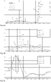
- FIG 8 To finish is in figure 8 a diagram 79 is shown below, in which the real speed 86 and the speed 87 used for control are plotted schematically. The deviations between the curves are small due to the analysis of the measured values and the corresponding consideration of a set of filter parameters.
- a Kalman filter is particularly preferably used in all of the configurations.
- the filter parameter set is determined as follows: The filter algorithm receives the (noisy) measured speed "Vr” and the (noisy) measured acceleration "Ar" of the connection units in relation to one another.
- Vr and Ar are measured by and derived from the sensor device 20, respectively.
- the speed signal and the acceleration signal can be derived from the sensor signal.
- the acceleration signal can also be determined directly via a separate acceleration sensor 47 .
- the estimated or derived speed “Vg” (reference number 87) and, if necessary, the estimated acceleration “Ag” of the relative movement of the connection units are determined with the Kalman filter.
- Vr and Ar are given in SI units and consequently in “m/s” and in “m/s2" respectively.
- variables "Q0" and "R” and “Vg” and “P” are defined.
- Vg corresponds to the estimated or derived speed 87 of the relative movement of the connection units to one another, which is used to determine the damping.
- the filter parameter set is then determined for each run and values for Q, Pp, K, Vg and P are determined.
- the parameters of the filter parameter set 82, 83 depend on the measured (noisy) values. To this end, a distinction is made as to whether the mathematical amount of the (noisy) measured acceleration "Ar" is greater than a predefined threshold value, preferably 5 in this case.
- Vp estimate speed Vg of the relative movement of the connection units to one another in the last run
- an estimated speed "Vg” (reference number 87 in 8 ) returned.
- An estimated acceleration "Ag” can also be determined and returned.
- the filter parameters and calculated values are stored as filter parameter set 83 at least until the next pass. In the next run, filter parameter set 83 becomes filter parameter set 82.
- the real speed 86 which was also recorded via additional sensors and which was subsequently determined in a complex manner after the measurement, is drawn in as a solid line. In normal driving, the real speed 86 is not available in the measurement quality for control. The real speed 86 is shown here for comparison only.
- the dashed line 88 shows the speed 88 filtered with a first set of filter parameters 82, which deviates considerably from the real speed 86 at the beginning of the measurement period shown.
- the dotted line 89 shows the course of the speed which was determined using a second set of filter parameters 83 with stronger filtering.
- the curve 89 shows a considerably smoother course than the curve 88 shown in dashed lines.
- the deviations from the course of the real speed 86 are relatively small. A slight time lag is recognizable, but it doesn't play a role with these small bumps.
- the filter parameter sets are switched over during the processing of the measured values, with the dotted curve profile 89 being used for the control up to about 14.765 seconds and with which there is a switchover from curve 89 to curve 88 from about 14.765 seconds becomes.
- the switching time 78 is shown. At this point in time, the measured speed and/or the measured acceleration has exceeded a predetermined level, so that a different set of filter parameters is selected. In all cases, more than two sets of filter parameters are also possible, for example one with less, one with medium and one with stronger filtering or smoothing.
- weighting can depend on the time interval (weighting to Example 25%, 50 and 100% for the penultimate reading, the last reading and the current value).
- Figure 9b shows the first period figure 9 enlarged, so that the deviations of the curve 88 from the real speed profile 86 are very clearly visible.
- a speed value is output for curve 88 which is four times the actual speed value that actually exists.
- a deviation in the curve 89 from the real speed 86 is very much smaller.
- Figure 9c shows the course of the stronger impact at the end of the in Figure 9a shown time period, with a good correspondence between the curves 88 and the real speed profile 86 being recognizable.
- the time offset 97 between the maximum of the real speed curve 86 and the maximum of the curve 89 is far more than 5 ms and is too large for such shocks to provide optimal damping properties.
- the invention provides a sufficiently fast and smooth and respectively adapted response behavior in all performance ranges of the damper 1 and thus an improved damper device 100
- the real-time control can be significantly improved, since the quality of the (measurement) signals used is improved, which means that a rough compression process when damping that has been noticeable in some situations up to now can be significantly reduced and practically eliminated.
Description
Die vorliegende Erfindung betrifft ein Verfahren zur Steuerung einer Dämpfereinrichtung. Dabei weist die Dämpfereinrichtung zwei relativ zueinander bewegbare Anschlusseinheiten auf, zwischen denen zur Dämpfung von Relativbewegungen wenigstens ein steuerbarer Dämpfer vorgesehen ist, wobei der Dämpfer wenigstens eine erste Dämpferkammer und wenigstens ein zugeordnetes Dämpfungsventil aufweist. Das Dämpfungsventil weist einen Dämpfungskanal mit einem magnetorheologischen Fluid auf. Dem Dämpfungsventil ist eine Magnetfelderzeugungseinrichtung zugeordnet, welche zur Erzeugung und Steuerung eines Magnetfeldes dient. Damit wird eine Art von Öffnungszustand des Dämpfungsventils beeinflusst.The present invention relates to a method for controlling a damper device. The damper device has two connection units that can be moved relative to one another, between which at least one controllable damper is provided for damping relative movements, the damper having at least one first damper chamber and at least one associated damping valve. The damping valve has a damping channel with a magnetorheological fluid. A magnetic field generating device is assigned to the damping valve and is used to generate and control a magnetic field. A type of opening state of the damping valve is thus influenced.
Die Dämpfung in Form von Schwingungen und/oder Stößen hat einen großen Einfluss auf z. B. die Fahreigenschaften von Fahrzeugen und stellt daher ein wichtiges Merkmal insbesondere bei sportlichen Fahrzeugen dar. Der Einsatz eines Dämpfers ermöglicht einen verbesserten Bodenkontakt und erlauben ein sportliches Fahren auch bei kurvenreichen Straßen. Im Millisekundenbereich schaltende Dämpfer auf magnetorheologischer Basis an den Rädern ermöglichen eine komfortable und sichere Betriebsweise. Bei Einsatz in z. B. der Lenksäule oder in Sicherheitsgurten zur Energieabsorption bei Unfällen ermöglichen derartige magnetorheologische Dämpfer eine optimale Anpassung an das Unfallszenario und damit geringstmögliche Verletzungen der Insassen.Damping in the form of vibrations and/or shocks has a major impact on e.g. B. the driving characteristics of vehicles and is therefore an important feature, especially in sporty vehicles. The use of a damper enables improved ground contact and allows sporty driving even on winding roads. Magnetorheological dampers on the wheels that switch in milliseconds enable comfortable and safe operation. When used in z. B. the steering column or in seat belts for energy absorption in accidents allow such magnetorheological dampers optimal adaptation to the accident scenario and thus the least possible injuries to the occupants.
Um die Vorteile einer Dämpfung an Fahrzeugen optimal ausnutzen zu können, ist in der Regel eine Einstellung der Dämpfungs- und gegebenenfalls der Federeigenschaften unerlässlich. Kriterien für die Einstellung sind dabei beispielsweise das Gewicht des zu dämpfenden Gegenstandes sowie die Eigenschaften des Geländes, in dem gefahren werden soll. Bei Fahrten auf glatter Fahrbahn sind andere Dämpfungseigenschaften sinnvoll als bei einer Fahrt durch das Gelände. Um jederzeit optimale Dämpfungseigenschaften zur Verfügung zu stellen, sind elektrisch steuerbare magnetorheologische Dämpfereinrichtungen bekannt geworden, die jederzeit eine bequeme Umstellung der Dämpfungseigenschaften ermöglichen.In order to be able to optimally exploit the advantages of damping on vehicles, it is usually essential to adjust the damping and, if necessary, the spring properties. Criteria for the setting are, for example, the weight of the object to be dampened and the properties of the terrain in which it is to be driven. When driving on slippery roads, different damping properties make sense than when driving off-road. In order to have optimal damping properties at all times To make available, electrically controllable magnetorheological damping devices have become known, which allow a comfortable changeover of the damping properties at any time.
Mit der
Die bekannte Dämpfereinrichtung funktioniert sehr zuverlässig und schaltet innerhalb weniger Millisekunden und wesentlich schneller als der Stand der Technik um, sodass die Dämpfereinrichtung z. B. beim Fahrradfahren während des Überfahrens einer Wurzel oder eines Steins kontinuierlich an die gerade vorherrschenden Bedingungen angepasst wird. Während zum Beispiel bei Fahrten auf glatter Fahrbahn der Dämpfer hart eingestellt bleibt, damit nicht unnötig Antriebsenergie in der Dämpfereinrichtung dissipiert wird. Die Dämpfereinrichtung arbeitet im Prinzip sehr zufriedenstellend. Es hat sich aber herausgestellt, dass in manchen Situationen, wenn zum Beispiel die Dämpfereinrichtung an einem Fahrrad manuell langsam eingefedert wird, die Dämpfereinrichtung nicht weich einfedert, was die Dämpfereinrichtung bei einer geringen Einfedergeschwindigkeit erlauben sollte, sondern ein kratzendes oder schabendes Feedback an die Hand des Benutzers abgibt. Ein ähnliches kratzendes oder schabendes Gefühl kann der Benutzer manchmal in den auf dem Lenker aufliegenden Handflächen spüren, wenn er eine nahezu ganz glatte Straße entlangfährt. Bei echten Stößen hingegen tritt so etwas nicht auf und der Stoßdämpfer dämpft erwartungsgemäß bei stärkeren und auch bei schwächeren Stößen. Das "Kratzen" oder "Schaben" oder "Rattern" tritt wahrnehmbar bei ganz geringen Belastungen auf. Es kann beim manuellen Einfedern der Eindruck entstehen, dass der Stoßdämpfer nicht schnell genug reagiert und während des Eindämpfens ein periodischer Übergang von sehr kurzem aktiven Blockieren und Loslassen und somit "kratzendem" Einfedern erfolgt. Die resultierende Resonanz ist für den Benutzer spürbar. Ein solches Phänomen tritt auch bei anderen Einsatzgebieten auf. Die Dämpfereinrichtung taucht dann nicht so weich ein, wie es sein sollte.The well-known damper device works very reliably and switches within a few milliseconds and much faster than the prior art, so that the damper device z. B. when cycling while driving over a root or a stone is continuously adapted to the currently prevailing conditions. For example, when driving on a slippery road surface, the damper remains set hard so that drive energy is not unnecessarily dissipated in the damper device. In principle, the damper device works very satisfactorily. However, it turned out that in In some situations, for example when the shock absorber on a bicycle is slowly compressed manually, the shock absorber does not compress softly, which the shock absorber should allow at a low compression speed, but gives a scratchy or scraping feedback to the user's hand. A similar scratching or scraping sensation can sometimes be felt by the user in the palms of the hands resting on the handlebars when driving down an almost completely slippery road. With real impacts, on the other hand, this does not happen and the shock absorber absorbs both stronger and weaker impacts as expected. The "scratching" or "scraping" or "rattling" occurs perceptibly at very low loads. When compressing manually, the impression can arise that the shock absorber does not react quickly enough and that there is a periodic transition from very brief active blocking and releasing and thus "scratchy" compression during damping. The resulting resonance is noticeable to the user. Such a phenomenon also occurs in other fields of application. The damping device then does not immerse as softly as it should be.
Zur Abhilfe wurden die Messdaten gefiltert, was aber zu einem erheblichen und fahrdynamisch oder performancemäßig nachteiligen Zeitverzug bei der Reaktion der Dämpfereinrichtung führte, wodurch Stöße zu spät und große Stöße nicht rechtzeitig abgefedert wurden. Dies alles findet im Bereich von Mikrosekunden statt. Um einen zu großen Zeitverzug bei der Reaktion der Dämpfereinrichtung auszuschließen, wurde die Messfrequenz erhöht, um aufgrund einer schnelleren Abfolge der Messwerte jederzeit die richtige Reaktion der Dämpfereinrichtung und somit einen weicheren Übergang in allen Bereichen zu erhalten. Aber auch eine Erhöhung der Messfrequenz brachte keine Verbesserung des Ein- und Ausfederungsverhaltens. Und das, obwohl die Dämpfereinrichtung innerhalb von wenigen Millisekunden voll einstellbar ist.To remedy the situation, the measurement data was filtered, but this led to a considerable time delay in the reaction of the damping device, which was disadvantageous in terms of driving dynamics or performance, as a result of which shocks were cushioned too late and large shocks were not cushioned in good time. This all takes place in the range of microseconds. In order to rule out an excessive time delay in the reaction of the damping device, the measuring frequency was increased in order to obtain the correct reaction of the damping device at all times and thus a smoother transition in all areas due to a faster sequence of the measured values. But even increasing the measurement frequency did not bring any improvement in compression and rebound behavior. And that despite the fact that the damping device can be fully adjusted within a few milliseconds.
Es ist deshalb die Aufgabe der vorliegenden Erfindung eine Dämpfereinrichtung zur Verfügung zu stellen, mit welcher ein schnelleres und damit besseres Ansprech- und nachfolgendes Dämpfverhalten einer steuerbaren Dämpfereinrichtung ermöglicht wird.It is therefore the object of the present invention to provide a damping device with which a faster and therefore better response and subsequent Damping behavior of a controllable damper device is made possible.
Diese Aufgabe wird durch ein Verfahren zur Steuerung eines Dämpfers mit den Merkmalen des Anspruchs 1 gelöst. Bevorzugte Weiterbildungen sind Gegenstand der Unteransprüche. Weitere Vorteile und Merkmale der vorliegenden Erfindung ergeben sich aus der allgemeinen Beschreibung und der Beschreibung der Ausführungsbeispiele.This object is achieved by a method for controlling a damper having the features of
Das erfindungsgemäße Verfahren dient zur Steuerung der Dämpfung einer Relativbewegung von zwei relativ zueinander bewegbaren Anschlusseinheiten, zwischen denen zur Dämpfung der Relativbewegungen wenigstens ein steuerbarer Dämpfer mit einem Dämpfungsventil mit einem magnetorheologischen Medium, Fluid oder Dämpfungsfluid vorgesehen ist. Dem wenigstens einen Dämpfungsventil ist wenigstens eine Magnetfelderzeugungseinrichtung zur Erzeugung und Steuerung eines Magnetfeldes zugeordnet. Es werden Messdatensätze wenigstens über eine Relativbewegung der Anschlusseinheiten zueinander erfasst und mit einer Filtereinrichtung aufbereitet. Ein abgeleiteter Datensatz umfasst insbesondere (einen Wert für) ein Geschwindigkeitssignal und (einen Wert für) ein Beschleunigungssignal für eine Relativbewegung der Anschlusseinheiten. Wenigstens ein aus einem erfassten Messdatensatz abgeleiteter Datensatz wird in der Speichereinrichtung hinterlegt. Wenigstens ein hinterlegter Datensatz wird analysiert und in Abhängigkeit von dem Ergebnis der Analyse wird ein Filterparametersatz bestimmt. Dabei wird bei betragsmäßig geringen Geschwindigkeitssignalen und betragsmäßig geringen Beschleunigungssignalen ein Filterparametersatz mit stärkerer Filterung und bei betragsmäßig größeren Geschwindigkeitssignalen oder betragsmäßig größeren Beschleunigungssignalen einen Filterparametersatz mit geringerer Filterung ausgewählt. Mit dem Filterparametersatz wird aus dem Messdatensatz ein Steuerdatensatz abgeleitet. Die Steuereinrichtung steuert mit dem Steuerdatensatz die Dämpfereinrichtung wenigstens teilweise und insbesondere auch vollständig.The method according to the invention serves to control the damping of a relative movement of two connection units that can be moved relative to one another, between which at least one controllable damper with a damping valve with a magneto-rheological medium, fluid or damping fluid is provided for damping the relative movements. At least one magnetic field generating device for generating and controlling a magnetic field is assigned to the at least one damping valve. Measurement data records are recorded at least via a relative movement of the connection units to one another and processed with a filter device. A derived data set includes in particular (a value for) a speed signal and (a value for) an acceleration signal for a relative movement of the connection units. At least one data set derived from a recorded measurement data set is stored in the memory device. At least one stored data set is analyzed and a set of filter parameters is determined depending on the result of the analysis. In the case of speed signals that are low in absolute value and acceleration signals that are low in absolute value, a filter parameter set with stronger filtering is selected and in the case of speed signals that are larger in magnitude or acceleration signals that are larger in terms of magnitude, a filter parameter set with less filtering is selected. A control data set is derived from the measurement data set with the filter parameter set. The control device uses the control data set to control the damper device at least partially and in particular also completely.
Das erfindungsgemäße Verfahren bietet viele Vorteile, da es eine in Abhängigkeit von der Analyse der Messdaten angepasste Aufbereitung vornimmt, wodurch jederzeit geeignete Dämpfungsparameter eingestellt werden.The method according to the invention offers many advantages, since it performs processing that is adapted as a function of the analysis of the measurement data, as a result of which suitable damping parameters can be set at any time.
Das erfindungsgemäße Verfahren wird mit einer Dämpfereinrichtung ausgeführt, die zwei relativ zueinander bewegbare Anschlusseinheiten umfasst, zwischen denen zur Dämpfung von Relativbewegungen wie z. B. Stößen oder Schwingungen wenigstens ein steuerbarer Dämpfer mit einem magnetorheologischen Medium, Fluid oder Dämpfungsfluid vorgesehen ist. Der Dämpfer weist wenigstens eine erste Dämpferkammer und wenigstens ein damit verbundenes Dämpfungsventil auf. Dem wenigstens einen Dämpfungsventil ist wenigstens eine Magnetfelderzeugungseinrichtung zugeordnet, welche zur Erzeugung und Steuerung eines Magnetfeldes in wenigstens einem Dämpfungskanal des Dämpfungsventils dient. In dem Dämpfungskanal ist wenigstens zum Teil das oder wenigstens ein magnetorheologisches Fluid vorgesehen. Weiterhin sind wenigstens eine Steuereinrichtung und wenigstens eine Speichereinrichtung vorgesehen. Wenigstens eine Sensoreinrichtung ist zur Erfassung von Messdatensätzen wenigstens über eine Relativbewegung der Anschlusseinheiten zueinander vorgesehen. Vorzugsweise ist eine Mehrzahl von Datensätzen in der Speichereinrichtung hinterlegbar. Zur Aufbereitung der Messdatensätze ist eine Filtereinrichtung vorgesehen. Wenigstens ein aus einem mit der Sensoreinrichtung bei der Relativbewegung der relativ zueinander bewegbaren Anschlusseinheiten erfassten Messdatensatz abgeleiteter Datensatz ist in der Speichereinrichtung hinterlegbar. Der Messdatensatz und/oder der abgeleitete Datensatz umfasst wenigstens ein Geschwindigkeitssignal und/oder wenigstens ein Beschleunigungssignal für die Relativbewegung der Anschlusseinheiten zueinander. Es ist eine Analyseeinrichtung vorgesehen, welche dazu ausgebildet und eingerichtet ist, wenigstens einen hinterlegten Datensatz zu analysieren und in Abhängigkeit von dem Ergebnis der Analyse einen Filterparametersatz zu bestimmen. Erfindungsgemäß ist die Steuereinrichtung dazu ausgebildet, bei betragsmäßig geringen Geschwindigkeitssignalen und Beschleunigungssignalen einen Filterparametersatz mit stärkerer Filterung und bei betragsmäßig größeren Geschwindigkeitssignalen oder Beschleunigungssignalen einen Filterparametersatz mit geringerer Filterung auszuwählen. Die Steuereinrichtung ist dazu ausgebildet mit dem Filterparametersatz aus dem Messdatensatz einen Steuerdatensatz abzuleiten, sodass die Steuereinrichtung mit dem Steuerdatensatz die Dämpfereinrichtung wenigstens zum Teil oder auch vollständig steuert.The method according to the invention is carried out with a damping device which comprises two connection units which can be moved relative to one another, between which, in order to dampen relative movements such as e.g. B. shocks or vibrations at least one controllable damper is provided with a magnetorheological medium, fluid or damping fluid. The damper has at least one first damper chamber and at least one damping valve connected thereto. At least one magnetic field generating device is assigned to the at least one damping valve, which is used to generate and control a magnetic field in at least one damping channel of the damping valve. The or at least one magnetorheological fluid is at least partially provided in the damping channel. At least one control device and at least one memory device are also provided. At least one sensor device is provided for acquiring measurement data sets at least via a relative movement of the connection units to one another. A plurality of data sets can preferably be stored in the memory device. A filter device is provided for processing the measurement data records. At least one data record derived from a measurement data record recorded with the sensor device during the relative movement of the connection units that can be moved relative to one another can be stored in the memory device. The measurement data set and/or the derived data set includes at least one speed signal and/or at least one acceleration signal for the movement of the connection units relative to one another. An analysis device is provided, which is designed and set up to analyze at least one stored data set and to determine a filter parameter set depending on the result of the analysis. According to the invention, the control device for this formed, in terms of absolute value low speed signals and acceleration signals, a filter parameter set with stronger filtering and, in the case of speed signals or acceleration signals that are larger in absolute value, a filter parameter set with less filtering. The control device is designed to use the filter parameter set to derive a control data set from the measurement data set, so that the control device uses the control data set to control the damper device at least partially or completely.
Die Steuerung der Dämpfereinrichtung mit dem erfindungsgemäßen Verfahren hat viele Vorteile. Ein erheblicher Vorteil der Steuerung der Dämpfereinrichtung besteht darin, dass mit der Analyseeinrichtung die erfassten Messdatensätze analysiert werden, sodass in Abhängigkeit von dem Ergebnis der Analyse ein Filterparametersatz ermittelt wird, mit dem aus dem Messdatensatz ein Steuerdatensatz abgeleitet wird, mit welchem das Dämpfungsventil des magnetorheologischen Dämpfers wenigstens teilweise gesteuert wird. Es wird durch Analyse der Messdatensätze der Relativbewegung der relativ zueinander bewegbaren Anschlusseinheiten jeweils ein geeigneter Filterparametersatz ermittelt, um ein schnelles und in allen Situationen ausreichend weiches Ansprechverhalten der Dämpfereinrichtung zu gewährleisten.Controlling the damper device using the method according to the invention has many advantages. A significant advantage of controlling the damper device is that the analysis device analyzes the recorded measurement data sets, so that a filter parameter set is determined depending on the result of the analysis, with which a control data set is derived from the measurement data set, with which the damping valve of the magnetorheological damper is at least partially controlled. A suitable set of filter parameters is determined by analyzing the measurement datasets of the relative movement of the connection units that can be moved relative to one another, in order to ensure a rapid response behavior of the damper device that is sufficiently soft in all situations.
Unter dem Begriff Datensatz wird im Sinne der vorliegenden Erfindung ein Datensatz mit wenigstens einem darin enthaltenen Wert oder Messwert verstanden. Es ist auch möglich und bevorzugt, dass ein Datensatz mehrere unterschiedliche Werte oder Parameter enthält. So kann ein Messdatensatz beispielsweise eine Weginformation und eine Geschwindigkeitsinformation und auch eine Beschleunigungsinformation und dergleichen mehr enthalten. Möglich ist es aber auch, dass ein Messdatensatz nur einen einzigen gemessenen Wert enthält. Das Gleiche gilt auch für einen abgeleiteten Datensatz, der in der Speichereinrichtung hinterlegt wird und auch für einen Steuerdatensatz, der aus dem hinterlegten Datensatz und/oder dem Messdatensatz ermittelt wird. In ähnlicher Weise kann ein Filterparametersatz einen oder mehrere Filterparameter enthalten. Vorzugsweise umfasst ein Parametersatz mehrere Parameter. Es ist aber auch möglich, dass ein Parametersatz nur einen Parameter enthält.In the context of the present invention, the term data set is understood to mean a data set with at least one value or measured value contained therein. It is also possible and preferred that a data set contains several different values or parameters. For example, a measurement data set can contain distance information and speed information as well as acceleration information and the like. However, it is also possible for a measurement data set to contain only a single measured value. The same also applies to a derived data set that is stored in the storage device and also to a control data set that is determined from the stored data set and/or the measurement data set. Similarly, a filter parameter set may contain one or more filter parameters. A set of parameters preferably includes several parameters. However, it is also possible for a parameter set to contain only one parameter.
Ein abgeleiteter Datensatz, der in der Speichereinrichtung hinterlegt wird, wird im Folgenden auch als "hinterlegter Datensatz" bezeichnet. Der abgeleitete und hinterlegte Datensatz kann identisch zu dem zugehörigen Messdatensatz sein oder wird durch Aufbereitung daraus gewonnen. Beispielsweise kann eine Normierung durchgeführt werden.A derived data record that is stored in the memory device is also referred to below as a “stored data record”. The derived and stored data set can be identical to the associated measurement data set or is obtained from it through processing. For example, a normalization can be carried out.
Insbesondere ist die Steuereinrichtung dazu ausgebildet und eingerichtet, wenigstens einen hinterlegten Datensatz zu analysieren und in Abhängigkeit von dem Ergebnis der Analyse einen Filterparametersatz aus einer Mehrzahl von Filterparametersätzen zu bestimmen und mit dem ermittelten Filterparametersatz aus dem Messdatensatz einen Steuerdatensatz abzuleiten. Insbesondere filtert die Filtereinrichtung Messdaten dann weniger intensiv, wenn eine intensivere Relativbewegung der Anschlusseinheiten zueinander vorliegt. Unter einer intensiveren Relativbewegung wird eine schnellere Relativbewegung oder eine schnellere Beschleunigung relativ zueinander oder gegebenenfalls auch eine absolute Geschwindigkeit oder Beschleunigung verstanden. Bei einer weniger intensiven Relativbewegung der Anschlusseinheiten zueinander wird hingegen intensiver gefiltert. Das bedeutet, dass die Messdaten bzw. der Wert oder die Werte eines Messdatensatzes stärker entrauscht werden. Dadurch kann ein glatterer zeitlicher Ablauf zur Verfügung gestellt werden.In particular, the control device is designed and set up to analyze at least one stored data set and, depending on the result of the analysis, to determine a filter parameter set from a plurality of filter parameter sets and to derive a control data set from the measurement data set using the determined filter parameter set. In particular, the filter device filters measurement data less intensively when there is a more intensive movement of the connection units relative to one another. A more intensive relative movement is understood to mean a faster relative movement or a faster acceleration relative to one another or possibly also an absolute speed or acceleration. In the case of a less intensive relative movement of the connection units to one another, on the other hand, the filtering is more intensive. This means that the measurement data or the value or values of a measurement data set are denoised to a greater extent. This can provide a smoother timing.
Die Steuereinrichtung steuert die Dämpfereinrichtung mittelbar oder unmittelbar unter Verwendung weiterer Komponenten, wie einer (Leistungs-)Elektronik und insbesondere unter Verwendung einer Magnetfelderzeugungseinrichtung. Jedenfalls wird eine Einstellung der Dämpfung des Dämpfereinrichtung mit dem Steuerdatensatz bewirkt.The control device controls the damper device directly or indirectly using further components such as (power) electronics and in particular using a magnetic field generating device. In any case, the damping of the damping device is adjusted with the control data record.
Aus den Messdatensätzen werden durch Aufbereitung und/oder durch Vorfilterung und/oder durch Filterung aufbereitete Datensätze erhalten, die vorzugsweise der weiteren Verarbeitung zugrunde gelegt werden.Prepared data records are obtained from the measurement data records by preparation and/or by pre-filtering and/or by filtering, which preferably form the basis for further processing be placed.
Die Messung der Messdatensätze erfolgt vorzugsweise mit einer Frequenz, die größer als 200 Hz oder 500 Hz und insbesondere größer 1 kHz beträgt. In der Speichereinrichtung können sowohl der aktuelle Messdatensatz als auch wenigstens ein vorangegangener Messdatensatz bzw. wenigstens der aktuelle abgeleitete Datensatz und/oder wenigstens ein zuvor abgeleiteter Datensatz hinterlegt werden. Möglich und bevorzugt ist es auch, dass der jeweils aktuelle Steuerdatensatz in der Speichereinrichtung gespeichert wird.The measurement of the measurement data records is preferably carried out with a frequency that is greater than 200 Hz or 500 Hz and in particular greater than 1 kHz. Both the current measurement data set and at least one previous measurement data set or at least the current derived data set and/or at least one previously derived data set can be stored in the memory device. It is also possible and preferred that the respectively current control data set is stored in the memory device.
Für die jeweilige Aufbereitung der Messdaten ergeben sich unterschiedliche Optionen. Bei einem ersten Durchlauf wird vorzugsweise ein voreingestellter Filterparametersatz geladen und es wird wenigstens ein erster Messdatensatz aufgenommen. Zunächst wird ein Steuerdatensatz mit dem voreingestellten Filterparametersatz aus dem Messdatensatz abgeleitet.There are different options for the respective processing of the measurement data. In a first run, a preset filter parameter set is preferably loaded and at least one first measurement data set is recorded. First, a control data set with the preset filter parameter set is derived from the measurement data set.
Danach wird gemäß einer ersten Variante in einer Schleife ein neuer bzw. aktueller Messdatensatz aufgenommen. Anschließend wird über den vorausgegangenen Steuerdatensatz ein Filterparametersatz gewählt oder abgeleitet. Mit dem derartig bestimmten Filterparametersatz wird ein aktueller Steuerdatensatz abgeleitet. Die Dämpfung der Dämpfereinrichtung wird unter Berücksichtigung dieses Steuerdatensatzes oder mit diesem Steuerdatensatz eingestellt.According to a first variant, a new or current measurement data record is then recorded in a loop. A filter parameter set is then selected or derived from the preceding control data set. A current control data set is derived with the filter parameter set determined in this way. The damping of the damper device is adjusted taking into account this control data set or with this control data set.
Beim nächsten Schleifendurchlauf wird der zuvor noch aktuelle Messdatensatz zu dem vorherigen Messdatensatz. Es wird der aktuelle Messdatensatz aufgenommen. Über den Steuerdatensatz einer vorgehenden Schleife und insbesondere der letzten Schleife wird ein Filterparametersatz ausgewählt und es wird mit dem aktuellen Messdatensatz und dem ausgewählten Filterparametersatz ein aktueller Steuerdatensatz abgeleitet, mit Hilfe dessen anschließend die Dämpfung eingestellt wird.The next time the loop is run, the measurement data set that was still current becomes the previous measurement data set. The current measurement data record is recorded. A filter parameter set is selected via the control data set of a preceding loop and in particular the last loop, and a current control data set is derived with the current measurement data set and the selected filter parameter set, with the aid of which the damping is then adjusted.
In einem alternativen Verfahren kann nach dem ersten Durchlauf eine andere Schleife durchgeführt werden. Dabei wird zunächst ebenfalls ein aktueller Messdatensatz aufgenommen. Über den aktuellen Messdatensatz wird ein Filterparametersatz ausgewählt aus dem aktuellen Messdatensatz wird mit dem ausgewählten Filterparametersatz ein aktueller Steuerdatensatz abgeleitet. Danach erfolgt die Einstellung der Dämpfung unter Berücksichtigung des aktuellen Steuerdatensatzes. Eventuell kann die Ermittlung des Filterparametersatzes auch iterativ erfolgen. Dabei wird ein erneuter Teilschleifendurchlauf zur Ermittlung des Filterparametersatzes durchgeführt, falls der aktuell ermittelte Steuerdatensatz von dem vorhergehenden Steuerdatensatz um ein bestimmtes Maß abweicht oder wenn der Steuerdatensatz bzw. die darin enthaltenden Werte bestimmte Grenzen unter- oder überschreiten.In an alternative method, after the first pass another loop to be performed. In this case, a current measurement data record is also initially recorded. A filter parameter set is selected via the current measurement data set and a current control data set is derived from the current measurement data set using the selected filter parameter set. The damping is then set taking into account the current control data record. The filter parameter set can possibly also be determined iteratively. A new partial loop run is carried out to determine the filter parameter set if the currently determined control data set deviates from the previous control data set by a certain amount or if the control data set or the values contained therein fall below or exceed certain limits.
Weiterhin ist noch eine weitere Variante der Schleife möglich, wonach zunächst ein aktueller Messdatensatz aufgenommen wird und mit dem aktuellen Messdatensatz unter Verwendung des vorhergehenden Filterparametersatzes ein aktueller Steuerdatensatz abgeleitet wird. Anhand des Steuerdatensatzes wird anschließend überprüft, ob der richtige Filterparametersatz gewählt wurde. Eventuell wird der Filterparametersatz neu ausgewählt und erneut ein neuer Steuerdatensatz bzw. aktueller Steuerdatensatz abgeleitet. Auch hier kann wiederum eine Überprüfung erfolgen, ob der korrekte Filterparametersatz ausgewählt wurde. Diese Iterationsschleife kann beliebig häufig durchgeführt werden. Vorzugsweise wird die Iterationsschleife in ihrer Anzahl begrenzt, um eine dauerhafte Schleife zu vermeiden. Mit dem aktuellen Steuerdatensatz wird schließlich die Dämpfung eingestellt.Another variant of the loop is also possible, according to which a current measurement data set is first recorded and a current control data set is derived from the current measurement data set using the previous filter parameter set. The control data set is then used to check whether the correct filter parameter set was selected. The filter parameter set is possibly reselected and a new control data set or current control data set is derived again. A check can also be carried out here as to whether the correct filter parameter set has been selected. This iteration loop can be repeated any number of times. Preferably, the iteration loop is limited in number to avoid a persistent loop. Finally, the damping is set with the current control data record.
In einer bevorzugten Weiterbildung ist in der Speichereinrichtung eine Mehrzahl an Filterparametersätzen hinterlegt und in Abhängigkeit von dem wenigstens einen hinterlegten Datensatz ist ein Filterparametersatz auswählbar.In a preferred development, a plurality of filter parameter sets are stored in the storage device and a filter parameter set can be selected as a function of the at least one stored data set.
Der hinterlegte Datensatz kann in allen Fällen der Messdatensatz sein, so wie er aufgenommen wird. Möglich ist es aber auch, dass mit der Sensoreinrichtung der erfasste Messdatensatz in einem ersten Aufbereitungsschritt aufbereitet wird, um zum Beispiel standardisierte Werte zu erhalten und anschließend den so ermittelten Datensatz in der Speichereinrichtung zu hinterlegen. Vorzugsweise wird eine Mehrzahl von miteinander gemessenen und aufbereiteten Datensätzen in der Speichereinrichtung hinterlegt. Je nach Speicherfähigkeit kann ein FIFO-Verfahren gewählt werden, sodass eine Anzahl der letzten Messdatensätze jeweils in der Speichereinrichtung verbleibt.In all cases, the stored data record can be the measurement data record as it is recorded. But it is also possible that with the sensor device the recorded measurement data set is processed in a first processing step in order to obtain, for example, standardized values and then to store the data set determined in this way in the storage device. A plurality of data sets that have been measured and processed together are preferably stored in the storage device. Depending on the storage capacity, a FIFO method can be selected so that a number of the most recent measurement data sets remain in the storage device.
In besonders bevorzugten Weiterbildungen umfasst die Analyseeinrichtung eine Vergleichseinrichtung und die Vergleichseinrichtung vergleicht einen hinterlegten Datensatz mit Vergleichsdaten und wählt in Abhängigkeit von dem Ergebnis des Vergleichs einen in der Speichereinrichtung abgelegten Filterparametersatz aus oder leitet ein Filterparametersatz ab und leitet aus dem Messdatensatz mit dem Filterparametersatz einen Steuerdatensatz ab. Eine solche Ausgestaltung ist sehr vorteilhaft, da ohne aufwendige Rechenoperationen sehr genaue Ergebnisse erzielbar sind.In particularly preferred developments, the analysis device comprises a comparison device and the comparison device compares a stored data set with comparison data and, depending on the result of the comparison, selects a filter parameter set stored in the memory device or derives a filter parameter set and derives a control data set from the measurement data set with the filter parameter set . Such a refinement is very advantageous since very precise results can be achieved without complex arithmetic operations.
In Abhängigkeit von dem wenigstens einen hinterlegten Datensatz ist vorzugsweise ein Filterparametersatz auswählbar. Das bedeutet, dass ein Filterparametersatz in Abhängigkeit von dem Inhalt wenigstens eines hinterlegten Datensatzes auswählbar ist. Dementsprechend kann mit der Vergleichseinrichtung ein Inhalt eines hinterlegten Datensatzes mit Vergleichsdaten verglichen werden.A set of filter parameters can preferably be selected as a function of the at least one stored data record. This means that a filter parameter set can be selected depending on the content of at least one stored data record. Accordingly, the content of a stored data record can be compared with comparison data using the comparison device.
In allen Ausgestaltungen ist es bevorzugt, dass eine Mehrzahl von Datensätzen in der Speichereinrichtung hinterlegbar ist. Dazu zählen neben den originalen Messdatensätzen auch die daraus abgeleiteten und in der Speichereinrichtung hinterlegten Datensätze sowie die in der Speichereinrichtung speicherbaren Steuerdatensätze und gegebenenfalls dergleichen mehr.In all of the configurations, it is preferred that a plurality of data sets can be stored in the memory device. In addition to the original measurement data records, this also includes the data records derived from them and stored in the memory device, as well as the control data records that can be stored in the memory device and possibly the like.
Besonders bevorzugt ist die Sensoreinrichtung dazu ausgebildet, wenigstens ein Wegsignal zu erfassen. In vorteilhaften Weiterbildungen ist die Steuereinrichtung dazu ausgebildet, aus einem Sensorsignal (insbesondere der der Sensoreinrichtung) ein Geschwindigkeitssignal für eine Relativbewegung der Anschlusseinheiten abzuleiten. Dazu ist eine Recheneinheit vorgesehen, die Teil der Steuereinrichtung sein kann. Vorzugsweise ist die Steuereinrichtung dazu ausgebildet, aus einem Sensorsignal (insbesondere der der Sensoreinrichtung) ein Beschleunigungssignal abzuleiten. Insbesondere ist die Steuereinrichtung dazu ausgebildet und eingerichtet aus einem Sensorsignal ein Beschleunigungssignal in der geforderten Güte abzuleiten. Dazu bestimmt die Steuereinrichtung in einer Frequenz von vorzugsweise größer 1 kHz aus dem Sensorsignal das Beschleunigungssignal. Zur Berechnung des Beschleunigungssignals ist vorzugsweise ebenfalls eine Recheneinheit vorgesehen, die auch Teil der Steuereinrichtung sein kann. Zur Berechnung des Beschleunigungssignals und des Geschwindigkeitssignals kann dieselbe Recheneinheit verwendet werden.The sensor device is particularly preferably designed to detect at least one displacement signal. In beneficial In further developments, the control device is designed to derive a speed signal for a relative movement of the connection units from a sensor signal (in particular that of the sensor device). For this purpose, a computing unit is provided, which can be part of the control device. The control device is preferably designed to derive an acceleration signal from a sensor signal (in particular that of the sensor device). In particular, the control device is designed and set up to derive an acceleration signal of the required quality from a sensor signal. For this purpose, the control device determines the acceleration signal from the sensor signal at a frequency of preferably greater than 1 kHz. A computing unit, which can also be part of the control device, is preferably also provided for calculating the acceleration signal. The same computing unit can be used to calculate the acceleration signal and the speed signal.
Bei dem erfindungsgemäßen Verfahren erfolgt die Steuerung der Dämpfereinrichtung insbesondere in Echtzeit. Das bedeutet, dass jederzeit eine Dämpfung eingestellt wird, wie sie für die aktuelle Belastungssituation erforderlich und sinnvoll ist. Die Dämpfereinrichtung wird nicht auf einen geeigneten "Mittelwert" eingestellt, sondern jederzeit wird (periodisch mit 1 kHz oder mehr) die Sensoreinrichtung ausgelesen und es werden Geschwindigkeitssignale und/oder Beschleunigungssignale erfasst und insbesondere aus Wegsignalen abgeleitet. Zu jedem Zeitpunkt wird nun in Echtzeit zu dem aktuellen Geschwindigkeitssignal eine passende Dämpfung eingestellt, da die Dämpfereinrichtung in wenigen Millisekunden frei einstellbar ist.In the method according to the invention, the damper device is controlled in particular in real time. This means that a damping is set at any time that is necessary and sensible for the current load situation. The damper device is not set to a suitable “average value”, but the sensor device is read out at any time (periodically at 1 kHz or more) and speed signals and/or acceleration signals are recorded and derived in particular from displacement signals. A suitable damping for the current speed signal is now set in real time at any point in time, since the damping device can be freely adjusted in a few milliseconds.
Vorzugsweise ist die unbeanspruchte Steuereinrichtung dazu ausgebildet, bei betragsmäßig geringen Geschwindigkeitssignalen und Beschleunigungssignalen einen Filterparametersatz mit stärkerer Filterung auszuwählen. Vorzugsweise ist die Steuereinrichtung dazu ausgebildet, bei betragsmäßig größeren Geschwindigkeitssignalen oder Beschleunigungssignalen einen Filterparametersatz mit geringerer Filterung auszuwählen. Das bedeutet, dass ein Filterparametersatz mit stärkerer Filterung ausgewählt wird, wenn das Geschwindigkeitssignal und das Beschleunigungssignal klein sind. Eine Filterparametersatz mit geringerer Filterung wird ausgewählt, wenn auch nur eines von beiden Signalen, nämlich Geschwindigkeitssignal und Beschleunigungssignal größer ist. Dadurch wird eine sehr schnelle Reaktion bei Stößen gewährleistet, während bei geringen Signalen ein stärkere Glättung erfolgt. Es wird aber verhindert, dass beim Auftreten eines starken Stoßes darauf erst (zu) spät reagiert wird.Preferably, the unclaimed control device is designed to select a filter parameter set with stronger filtering in the case of speed signals and acceleration signals that are low in terms of absolute value. The control device is preferably designed to select a filter parameter set with less filtering in the case of speed signals or acceleration signals that are larger in terms of absolute value. That means a Filter parameter set with stronger filtering is selected when the velocity signal and the acceleration signal are small. A filter parameter set with less filtering is selected even if only one of the two signals, namely the speed signal and the acceleration signal, is larger. This ensures a very fast response to bumps, while smoothing out more with low signals. However, this prevents a (too) late reaction to a strong impact.
Ein solches Rattern tritt, wie sich herausgestellt hat, insbesondere dann auf, wenn das Geschwindigkeitssignal unter 10% und eher unter 5% des im Betrieb typischen maximalen Geschwindigkeitssignals beträgt. Wenn bei einem kräftigen Stoß das maximal auftretende Geschwindigkeitssignal z. B. etwa 0,5 m/s oder 1 m/s beträgt, so kann ein "Kratzen" insbesondere bei Geschwindigkeitssignalen von bis zu 0,05 oder 0,02 m/s auftreten. Hier wird nun bei unter einer vorbestimmten Grenze liegenden Geschwindigkeitssignalen stärker gefiltert, sodass stärker entrauscht wird. Bei darüber liegenden Geschwindigkeitssignalen wird hingegen weniger stark oder gar nicht gefiltert. Werden allerdings relativ große Beschleunigungssignale oberhalb einer vorbestimmten Grenze ermittelt, wird das Geschwindigkeitssignal auch bei geringer Absolutgröße weniger intensiv gefiltert. Durch diese Kombination wird ein optimales Ergebnis erreicht. Bei starken Signalen wird wenig (oder gar nicht) gefiltert, sodass das Geschwindigkeitssignal (fast) direkt zur Einstellung der Dämpfung eingesetzt wird. Das ist vorteilhaft, da bei einer solchen Echtzeitdämpfung (bei "echten" Stößen) jeder Zeitverzug nachteilig sein kann. Bei geringen Stößen oder Vibrationen, die kleine Geschwindigkeitssignale und Beschleunigungssignale erzeugen, wird stärker gefiltert und insbesondere geglättet. Ein Zeitverzug spielt bei geringen Belastungen keine besondere Rolle.Such chattering has been found to occur particularly when the speed signal is below 10% and more likely below 5% of the maximum speed signal typical of operation. If the maximum occurring speed signal z. B. is about 0.5 m / s or 1 m / s, a "scratch" can occur in particular with speed signals of up to 0.05 or 0.02 m / s. In this case, speed signals below a predetermined limit are filtered more intensively, so that noise is removed more intensively. On the other hand, if the speed signals are higher, there is less filtering or no filtering at all. However, if relatively large acceleration signals are determined above a predetermined limit, the speed signal is filtered less intensively, even if the absolute value is small. This combination achieves an optimal result. When the signals are strong, there is little (or no) filtering, so the speed signal is used (almost) directly to adjust the damping. This is advantageous because with such real-time damping (with "real" impacts) any time delay can be disadvantageous. In the case of minor shocks or vibrations that generate small speed signals and acceleration signals, there is more filtering and, in particular, smoothing. A time delay does not play a particularly important role in the case of low loads.
Vorteilhafterweise ist die Sensoreinrichtung dazu geeignet und ausgebildet, das Wegsignal mit einer Auflösung von besser als 100 µm zu erfassen. Die Auflösung des Wegsignals kann auch besser als 50 µm oder besser als 30 µm und vorzugsweise besser als 10 µm sein. Mit einer Sensoreinrichtung, die Wegsignale mit einer sehr hohen Auflösung erfasst, kann eine sehr genaue Steuerung des Fahrwerks erfolgen.The sensor device is advantageously suitable and designed to detect the displacement signal with a resolution of better than 100 μm. The resolution of the path signal can also be better than 50 μm or better than 30 μm and preferably better than 10 μm be. With a sensor device that detects path signals with a very high resolution, the chassis can be controlled very precisely.
Insbesondere ist die Sensoreinrichtung dazu geeignet und ausgebildet, das Sensorsignal mit einer Messfrequenz von wenigstens 500 Hz oder wenigstens 1 kHz zu erfassen. Dabei kann die Messfrequenz auch 5 kHz erreichen oder überschreiten.In particular, the sensor device is suitable and designed to acquire the sensor signal with a measurement frequency of at least 500 Hz or at least 1 kHz. The measuring frequency can also reach or exceed 5 kHz.
In besonders bevorzugten Weiterbildungen umfasst der Dämpfer neben der ersten Dämpferkammer wenigstens eine zweite Dämpferkammer. Dabei sind die erste Dämpferkammer und die zweite Dämpferkammer über wenigstens das oder ein insbesondere steuerbares Dämpfungsventil miteinander gekoppelt. Besonders bevorzugt ist dem wenigstens einen Dämpfungsventil oder wenigstens einem Dämpfungsventil wenigstens eine Magnetfelderzeugungseinrichtung zugeordnet, welche zur Erzeugung und Steuerung eines Magnetfeldes in wenigstens ein Dämpfungskanal des Dämpfungsventils dient. Besonders bevorzugt ist in dem Dämpfungskanal wenigstens ein magnetorheologisches Fluid oder allgemein Medium vorgesehen. Durch ein magnetorheologisches Medium in dem Dämpfungskanal kann über eine Ansteuerung der Magnetfelderzeugungseinrichtung wenigstens eine Eigenschaft des Dämpfereinrichtung individuell und schnell eingestellt werden. Innerhalb weniger Millisekunden kann eine vollständige Neueinstellung der Dämpferkraft der Dämpfer bzw. des Dämpfereinrichtung erfolgen.In particularly preferred developments, the damper comprises at least one second damper chamber in addition to the first damper chamber. The first damper chamber and the second damper chamber are coupled to one another via at least one damping valve or one controllable damping valve in particular. Particularly preferably, the at least one damping valve or at least one damping valve is assigned at least one magnetic field generating device, which is used to generate and control a magnetic field in at least one damping channel of the damping valve. At least one magnetorheological fluid or medium in general is particularly preferably provided in the damping channel. By means of a magnetorheological medium in the damping channel, at least one property of the damping device can be set individually and quickly by controlling the magnetic field generating device. The damping force of the damper or damper device can be completely readjusted within a few milliseconds.
In bevorzugten Weiterbildungen des erfindungsgemäßen Verfahrens werden aus dem Messdatensatz wenigstens ein Geschwindigkeitssignal bzw. Geschwindigkeitsdaten abgeleitet. Ebenso können aus dem Messdatensatz wenigstens ein Beschleunigungssignal bzw. Beschleunigungsdaten abgeleitet werden.In preferred developments of the method according to the invention, at least one speed signal or speed data is derived from the measurement data set. Likewise, at least one acceleration signal or acceleration data can be derived from the measurement data set.
In bevorzugten Weiterbildungen wird ein Messdatensatz bzw. wenigstens ein Wert eines Messdatensatzes dann stärker gefiltert, wenn der Betrag des jeweiligen Wertes des Messdatensatzes kleiner ist als wenn der Betrag des Wertes bzw. der Werte des Messdatensatzes größer ist. Zur Unterscheidung, ob eine stärkere oder schwächere Filterung durchgeführt wird, können Schwellenwerte oder es kann ein Grenzwertsatz vorgesehen sein. Die Werte des Messdatensatzes können Wegwerte, Beschleunigungswerte und/oder Geschwindigkeitswerte enthalten. Unter einem Filtern kann auch ein Glätten der Werte verstanden werden. Unter dem Begriff "Betrag der Werte" wird der mathematische Betrag - also vorzeichenlos - verstanden.In preferred developments, a measurement data record or at least one value of a measurement data record is filtered more intensively when the absolute value of the respective value of the measurement data record is smaller than when the magnitude of the value or values of the measurement dataset is greater. Threshold values or a set of limit values can be provided to differentiate whether stronger or weaker filtering is carried out. The values of the measurement data set can contain path values, acceleration values and/or speed values. Filtering can also be understood as smoothing the values. The term "amount of values" means the mathematical amount - i.e. unsigned.
Insbesondere wird bei geringen Geschwindigkeiten der Relativbewegung stärker gefiltert als bei hohen Geschwindigkeiten. Dabei wird insbesondere das Geschwindigkeitssignal berücksichtigt, um zu entscheiden, ob stärker gefiltert oder schwächer gefiltert wird.In particular, the relative movement is filtered more strongly at low speeds than at high speeds. In particular, the speed signal is taken into account in order to decide whether filtering is stronger or weaker.
Ebenso ist es bevorzugt, dass bei geringen Beschleunigungen bzw. Beschleunigungssignalen der Relativbewegung stärker gefiltert wird als bei hohen Beschleunigungen bzw. hohen Beschleunigungssignalen.It is also preferred that the relative movement is filtered more strongly in the case of low accelerations or acceleration signals than in the case of high accelerations or high acceleration signals.
Unter dem Begriff "stärker" filtern wird hier ein intensiveres Filtern verstanden. Das bedeutet, dass stärker gefilterte Messdaten intensiver entrauscht werden. Das kann zum Beispiel dadurch erfolgen, dass eine größere Anzahl vorangegangener Messdaten berücksichtigt wird oder indem vorangegangene Messdaten mit einer höheren Gewichtung berücksichtigt werden. Eine stärkere Filterung führt zu einer stärkeren Glättung als eine schwächere Filterung. Das führt zu einer geringeren Grenzfrequenz. Kanten werden bei einer stärkeren Filterung runder als bei einer schwächeren Filterung, bei der die Grenzfrequenz höher ist. Eine stärkere Filterung führt insbesondere zu einem stärkeren Entrauschen (engl. denoising) als eine schwächere Filterung. Besonders bevorzugt werden Geschwindigkeitssignale und Beschleunigungssignale berücksichtigt, um zu entscheiden, wie stark gefiltert wird. Wenn das Geschwindigkeitssignal eine vorbestimmte Geschwindigkeitsgrenze oder wenn das Beschleunigungssignal eine vorbestimmte Beschleunigungsgrenze überschreitet, wird schwächer gefiltert, als wenn das Geschwindigkeitssignal und das Beschleunigungssignal kleiner als die jeweilige Grenze sind.The term “stronger” filtering is understood here to mean more intensive filtering. This means that more heavily filtered measurement data are denoised more intensively. This can be done, for example, by considering a larger number of previous measurement data or by considering previous measurement data with a higher weighting. More filtering results in more smoothing than less filtering. This leads to a lower cut-off frequency. Edges become more rounded with stronger filtering than with weaker filtering, where the cutoff frequency is higher. Stronger filtering leads in particular to stronger denoising than weaker filtering. Velocity signals and acceleration signals are particularly preferably taken into account in order to decide how strong the filtering is. When the speed signal exceeds a predetermined speed limit or when the acceleration signal exceeds a predetermined acceleration limit exceeds, the filtering is weaker than if the speed signal and the acceleration signal are smaller than the respective limit.
Es hat sich überraschenderweise herausgestellt, dass bei hohen Geschwindigkeitssignalen und/oder hohen Beschleunigungssignalen eine wesentlich schwächere Aufbereitung erforderlich ist als bei geringen Beschleunigungssignalen oder geringen Geschwindigkeitssignalen. Bei hohen Beschleunigungssignalen und/oder Geschwindigkeitssignalen, die bei dem Überfahren von Hindernissen auftreten, reicht eine geringe Filterung oder Glättung aus oder es kann vollständig darauf verzichtet werden. Bei kleinen oder kleinsten Stößen treten hingegen meist nur eine geringe Beschleunigung und eine geringe Relativgeschwindigkeit zwischen den Anschlusseinheiten der Dämpfereinrichtung auf. In Verbindung mit einer begrenzten Orts- und Geschwindigkeitsauflösung und der Digitalisierung (d. h. der Zeitdiskretisierung und der Wertdiskretisierung) des Messergebnisses ergibt sich hier schon durch das Prinzip bedingt ein Rauschen, wodurch die Messwerte ohne weitere Aufbereitung nicht immer zu einer zufriedenstellenden Betriebsweise der Dämpfereinrichtung führen. Eine Erhöhung der Messfrequenz führt dann sogar noch zu einer Vergrößerung des Rauschens, da bei höheren Messfrequenzen zwischen einzelnen Messungen jeweils noch kleinere Wertveränderungen ermittelt werden, die aber einen vergleichbaren Fehler aufweisen. Deshalb führt eine beliebige Erhöhung der Messfrequenz nicht zu einer Verbesserung des Messergebnisses, sondern kann kontraproduktiv sein, jedenfalls, wenn die Auflösung der Sensoreinrichtung nicht entsprechend mit vergrößert wird.Surprisingly, it turned out that in the case of high speed signals and/or high acceleration signals, a significantly weaker processing is required than in the case of low acceleration signals or low speed signals. In the case of high acceleration signals and/or speed signals, which occur when obstacles are driven over, a small amount of filtering or smoothing is sufficient or it can be dispensed with entirely. In the case of small or very small impacts, on the other hand, there is usually only a low acceleration and a low relative speed between the connection units of the damper device. In connection with a limited spatial and speed resolution and the digitization (i.e. the time discretization and the value discretization) of the measurement result, there is noise here due to the principle, which means that the measured values do not always lead to a satisfactory mode of operation of the damper device without further processing. An increase in the measurement frequency then even leads to an increase in the noise, since at higher measurement frequencies between individual measurements, smaller value changes are determined, which, however, have a comparable error. Therefore, any increase in the measurement frequency does not lead to an improvement in the measurement result, but can be counterproductive, at least if the resolution of the sensor device is not increased accordingly.
Da die Erfindung eine Dämpfereinrichtung und ein Verfahren zur Steuerung betrifft, bei dem die Steuerung des Dämpfers insbesondere in Echtzeit erfolgt, muss die Messfrequenz so hoch sein, dass jederzeit ausreichend schnell auf alle zu erwartenden Ereignisse reagiert werden kann. So muss eine Dämpfereinrichtung beim Auftreten eines Stoßes beim z. B. Überfahren von zum Beispiel einem Bumper, einem Schlagloch, einer Wurzel oder bei einem Sprung so schnell reagieren und die passende Dämpfereinstellung vornehmen, dass jeweils optimale oder doch wenigstens ausreichende Dämpfungseigenschaften vorliegen. Derartige Zeiterfordernisse bestehen z. B. bei Kraftfahrzeugen nach dem Stand der Technik heute regelmäßig nicht, da dort kein Stoß in Echtzeit gedämpft wird bzw. aufgrund der "langsamen" Dämpfer gedämpft werden kann, sondern maximal die generelle Dämpfereinstellung geändert wird. Erfindungsgemäß wird die Dämpfereinstellung der Dämpfereinrichtung während eines Stoßes vielfach angepasst, um jeweils optimale Dämpfereinstellungen zu haben. Deshalb müssen die Messfrequenz und die Reglerfrequenz der Steuereinrichtung entsprechend hoch sein, um das Konzept bei hoher Dynamik umzusetzen.Since the invention relates to a damper device and a control method in which the damper is controlled in real time, the measurement frequency must be high enough to allow a sufficiently quick reaction to all events to be expected at any time. So must a damping device when a shock occurs when z. E.g. driving over a bumper, a pothole, a root or a jump so quickly react and choose the right one Make damper settings that optimal or at least adequate damping properties are present. Such time requirements exist z. B. in motor vehicles according to the prior art today regularly not, since there no shock is damped in real time or can be damped due to the "slow" damper, but at most the general damper setting is changed. According to the invention, the damper setting of the damper device is adjusted many times during an impact in order to have optimal damper settings in each case. The measuring frequency and the controller frequency of the control device must therefore be correspondingly high in order to implement the concept with high dynamics.
Vorzugsweise werden wenigstens mehrere nacheinander erfasste Datensätze in der Speichereinrichtung gespeichert. Dadurch kann zur Aufbereitung des aktuellen Messdatensatzes auf mehrere zuvor erfasste Datensätze zurückgegriffen werden. Das ermöglicht beispielsweise eine gleitende Mittelung oder Glättung der Messdaten über mehrere Datensätze hinweg, z. B. über 2, 3, 4, 5, 6, 8 oder 10 Datensätze hinweg. Dadurch werden eine deutliche Reduzierung des digitalen Rauschens und des Rauschens als Ganzes erzielt.Preferably, at least a plurality of data sets recorded one after the other are stored in the memory device. This means that several previously recorded data sets can be used to process the current measurement data set. This enables, for example, a moving average or smoothing of the measurement data across several data sets, e.g. B. across 2, 3, 4, 5, 6, 8 or 10 records. This achieves a significant reduction in digital noise and noise as a whole.
Bei besonders hohen Messfrequenzen (z. B. 20 kHz oder 50 kHz oder 100 kHz oder mehr) kann auch eine Mittelung von einer gewissen Anzahl von Messungen durchgeführt werden und der Mittelwert von mehreren (z. B. 2, 3 oder 5 oder 10) Messungen wird als Messdatensatz ausgegeben. Ein solches "Oversampling" kann sowohl hardware- als auch softwareseitig durchgeführt werden. Wichtig ist, dass die Rate der Ausgabe der Messdatensätze ausreichend schnell ist.With particularly high measurement frequencies (e.g. 20 kHz or 50 kHz or 100 kHz or more), a certain number of measurements can also be averaged and the mean value of several (e.g. 2, 3 or 5 or 10) Measurements is output as a measurement data record. Such "oversampling" can be carried out both on the hardware and software side. It is important that the output rate of the measurement datasets is fast enough.
Vorzugsweise hängt eine Stärke oder Intensität der Glättung von dem hinterlegten Datensatz ab. Insbesondere hängt eine Stärkung der Glättung von dem aktuellen Datensatz ab. Dabei ist es möglich und bevorzugt, dass beispielsweise bei einer gleitenden Mittelung die Anzahl der für die Mittelung herangezogenen Datensätze variiert wird. Wird beispielsweise eine stärkere Filterung gewünscht, so kann die Glättung über entsprechend mehr nacheinander aufgenommene Datensätze durchgeführt werden, während bei einer schwächeren Filterung eine entsprechend geringere Anzahl von Datensätzen zur Mittelung berücksichtigt wird.A strength or intensity of the smoothing preferably depends on the stored data set. In particular, strengthening the smoothing depends on the current dataset. In this case, it is possible and preferred that, for example in the case of sliding averaging, the number of data sets used for the averaging is varied. Will, for example, stronger filtering desired, the smoothing can be carried out over a correspondingly larger number of data sets recorded one after the other, while with weaker filtering a correspondingly smaller number of data sets is taken into account for the averaging.
Möglich und bevorzugt ist es auch, dass die Anteilsfaktoren für eine gleitende Mittelung in Abhängigkeit von der Stärke der gewünschten Filterung variiert werden. Bei einer stärkeren Filterung können beispielsweise benachbarte oder vorausgegangene Messwerte mit der gleichen Gewichtung oder einer ähnlichen Gewichtung berücksichtigt werden wie der aktuelle Messwert. Beispielsweise können für eine stärkere Filterung der aktuelle Messwert und die vorangegangenen 4 Werte (10 Werte) zu jeweils 20% (10%) berücksichtigt werden. Bei einer schwächeren Filterung können hingegen (weniger Messwerte und) zeitlich weiter beabstandete Messwerte mit einem geringeren Anteilsfaktor berücksichtigt werden. Beispielsweise kann bei einer schwächeren Filterung der aktuelle Messwert mit 75% und der vorangegangene Messwert mit 25% berücksichtigt werden. Oder es werden der aktuelle Messwert und der davor jeweils zu 50 % berücksichtigt, während bei einer stärkeren Filterung der aktuelle Messwert und die beiden Messwerte davor jeweils mit gleicher Gewichtung (33%) berücksichtigt werden.It is also possible and preferred that the proportional factors for sliding averaging are varied as a function of the strength of the desired filtering. In the case of stronger filtering, for example, neighboring or previous measured values can be taken into account with the same weighting or a similar weighting as the current measured value. For example, the current measured value and the previous 4 values (10 values) can each be taken into account at 20% (10%) for stronger filtering. With weaker filtering, on the other hand, (fewer measured values and) measured values that are further apart in time can be taken into account with a lower proportional factor. For example, with weaker filtering, the current measured value can be taken into account with 75% and the previous measured value with 25%. Or the current measured value and the one before it are each taken into account with 50%, while with stronger filtering the current measured value and the two measured values before that are each taken into account with the same weighting (33%).
Neben einer Filterung über gleitende Mittelwerte können auch IIR-Filter (engl. Infinite Impulse Response) oder FIR-Filter (engl. Finite Impulse Response) oder andere Filter eingesetzt werden. Bevorzugt ist auch der Einsatz eines Kalman-Filters, wobei sich dann mit der Stärke der Filterung wenigstens ein Parameter des Kalman-Filters variiert wird.In addition to filtering using moving average values, IIR filters (Infinite Impulse Response) or FIR filters (Finite Impulse Response) or other filters can also be used. The use of a Kalman filter is also preferred, in which case at least one parameter of the Kalman filter is then varied with the strength of the filtering.
In allen Ausgestaltungen ist es besonders bevorzugt, dass mit der Sensoreinrichtung Messdatensätze mit einer Messfrequenz größer 250 Hz (insbesondere 500 Hz und vorzugsweise 1 kHz) erfasst werden und/oder dass die Steuereinrichtung Steuerdatensätze mit einer Steuerfrequenz größer 250 Hz (insbesondere 500 Hz und vorzugsweise 1 kHz) ermittelt. Vorzugsweise wird die Dämpfereinrichtung wenigstens zeitweise mit wenigstens dieser Steuerfrequenz von 250 Hz (insbesondere 500 Hz und vorzugsweise 1 kHz) angesteuert. Besonders bevorzugt sind die Messfrequenz und die Steuerfrequenz jeweils >2 kHz. Vorzugsweise sind die Messfrequenz und/oder die Steuerfrequenz größer als 5 kHz.In all configurations, it is particularly preferred that the sensor device records measurement data sets with a measurement frequency greater than 250 Hz (in particular 500 Hz and preferably 1 kHz) and/or that the control device records control data sets with a control frequency greater than 250 Hz (in particular 500 Hz and preferably 1 kHz) determined. Preferably, the damper device is at least temporarily with at least this Control frequency of 250 Hz (particularly 500 Hz and preferably 1 kHz) driven. The measuring frequency and the control frequency are particularly preferably >2 kHz. The measurement frequency and/or the control frequency are preferably greater than 5 kHz.
Besonders bevorzugt erfasst die Sensoreinrichtung Wegsignale mit einer Auflösung kleiner 100 µm oder kleiner als 50 µm. Vorzugsweise wird eine Auflösung kleiner als 30 µm und besonders bevorzugt kleiner als 10 µm erreicht. Dadurch können hoch aufgelöste Relativbewegungen ermittelt werden, wodurch die Genauigkeit steigt.The sensor device particularly preferably detects path signals with a resolution of less than 100 μm or less than 50 μm. A resolution of less than 30 μm and particularly preferably less than 10 μm is preferably achieved. This allows high-resolution relative movements to be determined, which increases accuracy.
In allen Ausgestaltungen ist es besonders bevorzugt, wenn die Messfrequenz und die Steuerfrequenz wenigstens zeitweise größer als 8 kHz und die Auflösung der Wegsignale wenigstens zeitweise kleiner als 10 µ oder 5 µm beträgt. Dabei ist es besonders bevorzugt, wenn die Messfrequenz kleiner als 50 kHz beträgt und vorzugsweise kleiner als 20 kHz beträgt oder wenn die Ausgabe von Messdatensätzen mit einer Frequenz kleiner als 50 kHz und vorzugsweise kleiner als 20 kHz erfolgt.In all of the configurations, it is particularly preferred if the measuring frequency and the control frequency are at least temporarily greater than 8 kHz and the resolution of the displacement signals is at least temporarily less than 10 μm or 5 μm. In this context, it is particularly preferred if the measurement frequency is less than 50 kHz and preferably less than 20 kHz or if measurement data sets are output at a frequency of less than 50 kHz and preferably less than 20 kHz.
Es ist auch möglich und bevorzugt, dass die Messfrequenz und die Steuerfrequenz unterschiedlich sind. Vorzugsweise ist die Messfrequenz größer als die Steuerfrequenz. Die Steuerfrequenz ist vorzugsweise größer 50 Hz und insbesondere größer 100 Hz und vorzugsweise größer 250 Hz oder größer 500 Hz. Die Messfrequenz ist insbesondere größer 250 Hz und vorzugsweise größer 500 Hz und besonders bevorzugt größer 1 kHz. Ein Verhältnis von Messfrequenz zu Steuerfrequenz kann größer 2 und insbesondere größer 4 und vorzugsweise größer 8 oder 16 sein.It is also possible and preferred that the measurement frequency and the control frequency are different. The measurement frequency is preferably greater than the control frequency. The control frequency is preferably greater than 50 Hz and in particular greater than 100 Hz and preferably greater than 250 Hz or greater than 500 Hz. The measuring frequency is in particular greater than 250 Hz and preferably greater than 500 Hz and particularly preferably greater than 1 kHz. A ratio of measurement frequency to control frequency can be greater than 2 and in particular greater than 4 and preferably greater than 8 or 16.
Insgesamt stellt die Erfindung ein vorteilhaftes Verfahren und eine vorteilhafte Dämpfereinrichtung zur Verfügung, womit in allen Lastbereichen ein angepasstes und jeweils glattes Ansprechverhalten ermöglicht wird. Überraschenderweise hat nicht eine Erhöhung der Messfrequenz das gewünschte Resultat gebracht, sondern eine Analyse der jeweiligen Messwerte und eine in Abhängigkeit von den jeweiligen Messwerten durchgeführte Filterung. Es hat sich nämlich herausgestellt, dass die Messwertaufnahme zuvor nicht zu langsam war, sondern bei geringen Dämpfergeschwindigkeiten eher zu schnell, da auch aufgrund des zwangsläufig auftretenden Rauschens, welches wenigstens zum Teil auch durch Digitalisierungseffekte bewirkt wird, mit zunehmender Messfrequenz bei geringen Änderungsgeschwindigkeiten der Messgrößen die relativen Fehler zunehmen, weshalb der Dämpfereinrichtung aufgrund seiner hohen Reaktionsgeschwindigkeit die rauschbehafteten Werte zu schnell einstellte. Bei besonders starken Stößen ändern sich hingegen die Messwerte von einem Schritt zum nächsten mit einer solchen Geschwindigkeit, dass durch die Digitalisierung keine nennenswerten Fehler eingebracht werden.Overall, the invention makes available an advantageous method and an advantageous damper device, with which an adapted and respectively smooth response behavior is made possible in all load ranges. Surprisingly, it was not an increase in the measuring frequency that brought the desired result, but rather an analysis of the respective measured values and one carried out as a function of the respective measured values filtering. It has been found that the recording of measured values was not too slow before, but rather too fast at low damper speeds, since also due to the noise that inevitably occurs, which is at least partly also caused by digitization effects, with increasing measuring frequency at low rates of change of the measured variables, the relative errors increase, which is why the damper set the noisy values too quickly due to its high reaction speed. In the case of particularly strong impacts, on the other hand, the measured values change from one step to the next at such a speed that the digitization does not introduce any significant errors.
In einer Variante umfasst eine unbeanspruchte Dämpfereinrichtung zwei relativ zueinander bewegbare Anschlusseinheiten, zwischen denen zur Dämpfung von Relativbewegungen wie z. B. Stößen oder Schwingungen wenigstens ein steuerbarer magnetorheologischer Dämpfer vorgesehen ist. Es sind wenigstens eine Steuereinrichtung und wenigstens eine Speichereinrichtung vorgesehen. Wenigstens eine Sensoreinrichtung ist zur Erfassung von Messdatensätzen wenigstens über eine Relativbewegung der Anschlusseinheiten zueinander vorgesehen. Zur Aufbereitung der Messdatensätze ist eine Filtereinrichtung vorgesehen. Wenigstens ein aus einem mit der Sensoreinrichtung bei der Relativbewegung der relativ zueinander bewegbaren Anschlusseinheiten erfassten Messdatensatz abgeleiteter Datensatz ist in der Speichereinrichtung hinterlegbar. Es ist eine Analyseeinrichtung vorgesehen, welche dazu ausgebildet und eingerichtet ist, wenigstens einen hinterlegten Datensatz zu analysieren und in Abhängigkeit von dem Ergebnis der Analyse einen Filterparametersatz zu bestimmen und mit dem Filterparametersatz aus dem Messdatensatz einen Steuerdatensatz abzuleiten, sodass die Steuereinrichtung mit dem Steuerdatensatz die Dämpfereinrichtung wenigstens zum Teil oder auch vollständig steuert. Weiterbildungen enthalten einige oder alle Merkmale der zuvor beschriebenen Dämpfereinrichtung.In one variant, an unclaimed damper device comprises two connection units that can be moved relative to one another, between which, for damping relative movements such as e.g. B. shocks or vibrations at least one controllable magnetorheological damper is provided. At least one control device and at least one memory device are provided. At least one sensor device is provided for acquiring measurement data sets at least via a relative movement of the connection units to one another. A filter device is provided for processing the measurement data records. At least one data record derived from a measurement data record recorded with the sensor device during the relative movement of the connection units that can be moved relative to one another can be stored in the memory device. An analysis device is provided, which is designed and set up to analyze at least one stored data set and, depending on the result of the analysis, to determine a filter parameter set and to derive a control data set from the measurement data set using the filter parameter set, so that the control device uses the control data set to control the damper device at least partially or fully controlled. Developments contain some or all of the features of the damper device described above.
Als vorteilhaft hat sich auch eine Erhöhung der Messgenauigkeit und/oder der Messauflösung herausgestellt. Besonders vorteilhaft sind eine aufeinander abgestimmte Anpassung von Messauflösung und Messfrequenz und eine Filterung der Messdaten nach Analyse der Messdaten. Dabei erfolgt die Auswertung in Echtzeit.An increase in measurement accuracy has also proven advantageous and/or the measurement resolution. A coordinated adjustment of measurement resolution and measurement frequency and filtering of the measurement data after analysis of the measurement data are particularly advantageous. The evaluation takes place in real time.
In allen Ausgestaltungen ist es vorzugsweise möglich, dass die Filtereinrichtung in die Steuereinrichtung integriert ist. Die Filterung kann wenigstens zum Teil oder vollständig durch eine Recheneinheit der Steuereinrichtung durchgeführt werden.In all configurations, it is preferably possible for the filter device to be integrated into the control device. The filtering can be carried out at least partially or completely by a computing unit of the control device.
Weitere Vorteile und Merkmale der vorliegenden Erfindung ergeben sich aus den Ausführungsbeispielen, welche mit Bezug auf die beiliegenden Figuren erläutert werden.Further advantages and features of the present invention result from the exemplary embodiments, which are explained with reference to the enclosed figures.
In den Figuren zeigen:
- Fig. 1
- eine schematische Darstellung eines Fahrrads mit einer Dämpfereinrichtung;
- Fig. 2
- eine schematische Darstellung der Steuerung der Dämpfereinrichtung nach
Fig. 1 ; - Fig. 3
- eine schematische geschnittene Darstellung einer weiteren Dämpfereinrichtung z. B. für das
Fahrrad nach Figur 1 ; - Fig. 4
- die Sensoreinrichtung der Dämpfereinrichtung nach
Figur 3 in einer vergrößerten Darstellung; - Fig. 5
- eine alternative Sensoreinrichtung für die Dämpfereinrichtung nach
Figur 3 ; - Fig. 6
- eine weitere Sensoreinrichtung für die Dämpfereinrichtung nach
Figur 3 ; - Fig. 7
- noch eine Sensoreinrichtung für die Dämpfereinrichtung nach
Figur 3 ; - Fig. 8
- eine schematische Darstellung der Datenaufbereitung der mit der Sensoreinrichtung gemessenen Daten; und
- Fig.
- 9a bis 9c reale Messdaten der Dämpfereinrichtung nach
Fig.3 .
- 1
- a schematic representation of a bicycle with a damping device;
- 2
- a schematic representation of the control of the
damper device 1 ; - 3
- a schematic sectional view of another damper device z. B. for the bike
figure 1 ; - 4
- the sensor device of the damper device
figure 3 in an enlarged view; - figure 5
- an alternative sensor device for the damper device
figure 3 ; - 6
- a further sensor device for the damper device
figure 3 ; - 7
- another sensor device for the damper device
figure 3 ; - 8
- a schematic representation of the data preparation of the data measured with the sensor device; and
- figure
- 9a to 9c real measurement data of the damper device
Fig.3 .
Mit Bezug auf die beiliegenden Figuren werden Ausführungsbeispiele und Varianten der Erfindung anhand einer Dämpfereinrichtung 100 mit einem Dämpfer 1 beschrieben. Die Dämpfereinrichtung 100 wird hier an einem Fahrrad 200 eingesetzt.Exemplary embodiments and variants of the invention based on a
Das Vorderrad 111 verfügt über eine als Federgabel 114 ausgeführte Dämpfereinrichtung 100 und an dem Hinterrad 112 ist ein als Hinterraddämpfer 115 ausgeführte Dämpfereinrichtung 100 vorgesehen.The
Die Dämpfereinrichtung 100 umfasst im einfachsten Fall einen Dämpfer 1 und eine Steuereinrichtung 46. Möglich ist es auch, dass die Dämpfereinrichtung 100 zwei Dämpfer 1 (Federgabel und Hinterradstoßdämpfer) umfasst, an denen jeweils eine Steuereinrichtung 46 vorgesehen ist. Oder die Dämpfereinrichtung 100 umfasst zwei Dämpfer 1 und eine (zentrale) Steuereinrichtung 60. Die (zentrale) Steuereinrichtung 60 kann zur Einstellung der Vorgaben und zur Koordination der beiden Dämpfer dienen.In the simplest case, the
Die zentrale Steuereinrichtung 60 ist hier zusammen mit einer Batterieeinheit 61 in einem trinkflaschenartigen Behälter vorgesehen und an dem Unterrohr angeordnet, wo sonst eine Trinkflasche angeordnet ist, kann aber auch im Rahmen vorgesehen werden. Die zentrale Steuereinrichtung 60 kann auch an dem Lenker 116 angeordnet werden.The
Die Steuerung der Dämpfer 1 und weiterer Fahrradkomponenten kann in Abhängigkeit verschiedenster Parameter erfolgen und erfolgt im Wesentlichen auch anhand von sensorisch erfassten Daten. Insbesondere kann auch eine Alterung des Dämpfungsmediums, der Federeinrichtung und weiterer Komponenten berücksichtigt werden. Es ist auch bevorzugt, die Temperatur der Dämpfereinrichtung 100 oder des Dämpfers 1 zu berücksichtigen (Federgabel 114 und/oder Hinterradstoßdämpfer 115).The
Die Dämpfereinrichtung 100 und deren zentrale Steuereinrichtung 60 werden über Bedieneinrichtungen 150 bedient. Es sind zwei Bedieneinrichtungen 150 vorgesehen, nämlich eine Betätigungseinrichtung 151 und eine Einstelleinrichtung 152. Die Betätigungseinrichtung 151 weist mechanische Eingabeeinheiten 153 an den seitlichen Enden oder in der Nähe der seitlichen Enden des Lenkers 116 auf. Die Einstelleinrichtung 152 kann als Fahrradcomputer ausgeführt sein und kann einen berührungsempfindlichen Bildschirm aufweisen und ebenfalls am Lenker 116 positioniert werden. Möglich ist es aber auch, dass ein Smartphone 160, oder ein Tablett oder dergleichen als Einstelleinrichtung 152 eingesetzt wird und beispielsweise in der Tasche oder in dem Rucksack des Benutzers aufbewahrt wird, wenn keine Veränderung der Einstellungen vorgenommen wird.The
Das Display 49 ist insbesondere als grafische Bedieneinheit oder Touchscreen 57 ausgeführt, sodass der Benutzer beispielsweise eine dargestellte Dämpferkennlinie 10 mit den Fingern berühren und durch Ziehen ändern kann. Dadurch kann aus der durchgezogen dargestellten Dämpferkennlinie 10 die auch dargestellte Dämpferkennlinie 50 erzeugt werden, die dann ab sofort für die Steuerung eingesetzt wird. Die Veränderung der Dämpferkennlinien 10, 50 ist auch während der Fahrt möglich.The
Die Einstelleinrichtung 152 kann auch als Fahrradcomputer dienen und Informationen über die aktuelle Geschwindigkeit, sowie über die Durchschnittsgeschwindigkeit und/oder die Tages-, Tour, Runden- und Gesamtkilometer anzeigen. Möglich sind auch die Anzeige der aktuellen Position, der momentanen Höhe der gefahrenen Strecke sowie des Streckenprofils und auch eine mögliche Reichweite unter den aktuellen Dämpfungsbedingungen.The
Die Steuereinrichtungen 46 und/oder 60 sind mit wenigstens einer Sensoreinrichtung 20 oder mit mehreren Sensoren verbunden. Die Steuereinrichtung 60 ist über Netzwerkschnittstellen 54 oder Funknetzschnittstellen 55 mit Steuereinrichtungen 46 der Dämpfer 1 am Vorderrad und am Hinterrad verbunden. Die möglicherweise an jedem Dämpfer 1 vorgesehene Steuereinrichtung 46 sorgt für die lokale Steuerung und kann jeweils eine Batterie aufweisen oder aber mit der zentralen Batterieeinheit 61 verbunden sein. Bevorzugt ist es, dass die Steuerung beider Dämpfer über die Steuereinrichtung 60 erfolgt. Möglich ist auch eine lokale Steuerung der Dämpfer 1 über zugeordnete Steuereinrichtung 46.The
Vorzugsweise ist jedem Dämpfer 1 wenigstens eine Sensoreinrichtung 20 zugeordnet, um Relativbewegungen zwischen den Komponenten bzw. Anschlusseinheiten 101 und 102 zu erfassen. Insbesondere ist eine Relativposition der Komponenten 101 und 102 relativ zueinander bestimmbar. Die Sensoreinrichtung 20 ist vorzugsweise als (relativer) Wegsensor ausgebildet oder umfasst wenigstens einen solchen und ist in den Dämpfer 100 integriert. Möglich und bevorzugt ist auch der Einsatz wenigstens eines zusätzlichen Beschleunigungssensors 47. Die Sensoreinrichtung 20 kann auch vorzugsweise als Geschwindigkeitssensor ausgebildet sein oder einen solchen umfassen.At least one
Anhand der in der Speichereinrichtung 45 abgelegten Dämpferkennlinie 10 des Dämpfers 100 werden nach Ermittlung eines Kennwerts für die Relativgeschwindigkeit die zugehörige Dämpfungskraft und eine passende Federkraft eingestellt. Eine passende Federkraft kann über das Gewicht des Fahrers ermittelt werden. Beispielsweise kann durch automatische Ermittlung der Einfeder-Position (sag) nach dem Aufsetzen eines Fahrers das Gewicht des Fahrers abgeleitet werden. Aus dem Einfederungsweg beim Aufsetzen des Fahrers auf das Fahrrad kann auf einen geeigneten Luftdruck in der Fluidfeder bzw. Gasfeder geschlossen werden, der dann automatisch sofort oder im Laufe des Betriebs eingestellt oder angenähert wird.Based on the damper
In
Der (vgl.
Im Schritt 56 wird dann anschließend aus den aktuellen Messwerten unter Berücksichtigung der vorbestimmten oder ausgewählten Dämpferkennlinie die zugehörige einzustellende Dämpfungskraft abgeleitet. Daraus wird ein Maß für die aktuell einzustellende Feldstärke bzw. Stromstärke abgeleitet, mit welcher die einzustellende Dämpfungskraft wenigstens näherungsweise erreicht wird. Das Maß kann die Feldstärke selbst sein oder aber z. B. die Stromstärke angeben, mit welcher die einzustellende Dämpfungskraft wenigstens etwa erreicht wird.In
Im darauf folgenden Schritt 70 wird die aktuell einzustellende Feldstärke erzeugt oder die entsprechende Stromstärke an die elektrische Spuleneinrichtung 11 als Felderzeugungseinrichtung angelegt, sodass innerhalb eines einzelnen Zyklus bzw. einer Zeitperiode des Steuerkreislaufes 12 die Dämpfungskraft erzeugt wird, die bei der gewählten oder vorbestimmten Dämpferkennlinie zu der aktuellen Relativgeschwindigkeit der ersten Anschlusseinheit 101 zu der zweiten Anschlusseinheit 102 vorgesehen ist. Anschließend startet der nächste Zyklus und es wird wieder Schritt 52 durchgeführt. Jeder Zyklus benötigt insbesondere weniger als 30 ms und insbesondere weniger als 20 ms. Es ist möglich, dass die Erfassung der Sensordaten und die nachfolgenden Berechnungen mit höherer Geschwindigkeit durchgeführt werden (z.B. ein insbesondere ganzzahliges Vielfaches der Messfrequenz).In the
Der Kolben 5 ist mit einer Kolbenstange 6 verbunden. In dem Dämpfungskolben 5 ist das gestrichelt eingezeichnete magnetorheologische Dämpfungsventil 8 vorgesehen, welches hier eine elektrische Spule 11 als Felderzeugungseinrichtung umfasst, um eine entsprechende Feldstärke zu erzeugen. Das Dämpfungsventil 8 bzw. der "Öffnungszustand" des Dämpfungsventils wird über die elektrische Spuleneinrichtung 11 angesteuert.The
Die Spule der elektrischen Spuleneinrichtung 11 ist nicht in Umfangsrichtung um die Kolbenstange 6 herumgewickelt, sondern um eine Achse, die sich quer zur Längserstreckung der Kolbenstange 6 (und hier parallel zur Zeichnungsebene) erstreckt. Eine Relativbewegung findet hier linear statt und erfolgt in der Bewegungsrichtung 18. Die Magnetfeldlinien verlaufen dabei in dem Zentralbereich des Kerns etwa senkrecht zur Längserstreckung der Kolbenstange 6 und durchtreten somit etwa senkrecht die Dämpfungskanäle 7. Ein Dämpfungskanal befindet sich hinter der Zeichnungsebene und ist gestrichelt eingezeichnet. Dadurch wird eine effektive Beeinflussung des sich in den Dämpfungskanälen 7 befindenden magnetorheologischen Fluides bewirkt, sodass der Durchfluss durch das Dämpfungsventil 8 effektiv gedämpft werden kann.The coil of the
In dem Dämpfergehäuse 2 ist ein Ausgleichskolben 72 angeordnet, der einen Ausgleichsraum 71 für das Volumen der beim Einfedern eintretenden Kolbenstange abtrennt.A compensating
Nicht nur in dem Dämpfungsventil 8, sondern hier in den beiden Dämpfungskammern 3 und 4 befindet sich hier überall (außer im Ausgleichsraum 71) ein magnetorheologisches Fluid als feldempfindliches Medium. In dem Ausgleichsraum 71 befindet sich vorzugsweise ein Gas oder Gasgemisch.Not only in the damping valve 8, but here in the two damping chambers 3 and 4, there is a magnetorheological fluid as a field-sensitive medium everywhere (except in the compensation chamber 71). A gas or gas mixture is preferably located in the
Die Dämpfereinrichtung 100 weist eine Sensoreinrichtung 20 auf. Die Sensoreinrichtung 20 umfasst jeweils einen Detektorkopf 21 und eine strukturiert ausgebildete Maßstabeinrichtung 30.The
Die Maßstabeinrichtung 30 umfasst hier ein Sensorband mit Permanentmagneteinheiten als Felderzeugungseinheiten. Die Pole der Permanentmagneteinheiten wechseln sich alternierend ab, sodass entlang der Bewegungsrichtung des Detektors 22 alternierend Nord-Südpole angeordnet sind. Die magnetische Feldstärke wird durch den Detektorkopf ausgewertet und daraus wird die jeweils aktuelle Position 19 ermittelt. Der Aufbau und die Funktion der Sensoreinrichtung 20 werden im Folgenden noch detaillierter erläutert.The
Zur besseren Verdeutlichung sind in
Die Federeinrichtung 42 erstreckt sich hier wenigstens teilweise um das Dämpfergehäuse 2 herum und umfasst ein Federgehäuse 76. Ein Ende des Dämpfers 1 ist mit einem Federungskolben 37 verbunden bzw. bildet einen solchen. Der Federungskolben 37 trennt die Positivkammer 43 von einer Negativkammer 44. Das Dämpfergehäuse 2 mit der ersten Dämpferkammer 3 taucht in das Federgehäuse 76 ein bzw. ist davon umgeben. Je nach Einfederungszustand umgibt das Federgehäuse 76 auch die zweite Dämpferkammer wenigstens zum Teil.The spring device 42 here extends at least partially around the
Das Federgehäuse 76 wird zu dem Ende der Anschlusseinheit 101 durch einen Deckel 77 abgeschlossen. Dort wird auch das Anschlusskabel 38 für die elektrische Spuleneinrichtung 11 herausgeführt. Vorzugsweise wird dort auch ein elektrisches Anschlusskabel für die Sensoreinrichtung 20 nach außen herausgeführt.The
Die Sensoreinrichtung 20 umfasst zwei Sensorteile, nämlich den Detektorkopf 21, der in der hier weiter oben dargestellten Variante innerhalb der Positivkammer 43 der Federeinrichtung 42 angeordnet ist. Die Sensoreinrichtung 20 umfasst als weiteres Sensorteil die Maßstabeinrichtung 30, die in dieser Variante in dem Federgehäuse 76 angeordnet oder aufgenommen ist. Je nach Ausgestaltung und Materialwahl des Federgehäuses 76 und nach Messprinzip der Sensoreinrichtung 20 kann die Maßstabeinrichtung 30 in die Wandung des Federgehäuses 76 integriert sein oder aber auf der Innenwandung des Federgehäuses 76 angeordnet werden.The
Möglich ist es auch, die Maßstabeinrichtung 30 in eine Längsnut auf der Außenwandung des Federgehäuses 76 einzusetzen. Das ist z. B. möglich, wenn die Sensoreinrichtung auf der Auswertung magnetischer Feldstärken beruht oder magnetische Feldstärken einsetzt und wenn das Federgehäuses 76 beispielsweise aus einem Faserverbundwerkstoff oder aus einem anderen magnetisch nicht leitenden Material besteht.It is also possible to fit the
In der anderen dargestellten Variante ist die Maßstabeinrichtung 30 beispielsweise in die Kolbenstange integriert. Die Maßstabeinrichtung 30 kann z. B. in eine Nut der Kolbenstange 6 eingesetzt sein. Vorzugsweise besteht die Kolbenstange 6 aus einem magnetisch nicht oder schlecht leitenden Material.In the other variant shown, the
Der Detektorkopf 21 umfasst in beiden Alternativen zwei Detektoren 22 und 23, die hier in Bewegungsrichtung 18 versetzt zueinander angeordnet sind. In der ersten Alternative ist der Detektorkopf 21 an dem Federungskolben 37 angeordnet und insbesondere daran befestigt. In der ersten Alternative sitzt der Detektorkopf 21 radial weiter außen benachbart (aber beabstandet) von der Maßstabeinrichtung 30 in dem Federgehäuse 76. In der zweiten Alternative ist der Detektorkopf 21 radial weiter innen an dem Federungskolben 37 angeordnet.In both alternatives, the
Die Maßstabeinrichtung 30 weist in jedem Fall eine sich über eine Messstrecke 31 erstreckende Struktur 32 auf, über die sich die physikalischen Eigenschaften der Maßstabeinrichtung 30 periodisch ändern.In any case, the
Vorzugsweise sind auf der Maßstabeinrichtung 30 Sensorabschnitte 33 (vergleiche
Dabei kann, wie schon in
In einer solchen Ausgestaltung ist der Detektorkopf 21 mit Detektoren 22 und 23 ausgerüstet, die ein Magnetfeld detektieren. Beispielsweise können die Detektoren 22 und 23 als elektrische Spulen ausgebildet sein oder beispielsweise als Hallsensoren ausgeführt sein, um die Intensität eines magnetischen Feldes der Permanentmagneten zu erfassen.In such an embodiment, the
Findet nun eine Relativbewegung der Anschlusseinheiten 101 und 102 des Dämpfers 1 zueinander statt, so ändert sich die Position 19 des Dämpfers 1 und es verschiebt sich die relative Position des Detektorkopfs 21 relativ zu der Maßstabeinrichtung 30. Durch Auswertung der Signalstärke eines Detektors 22, 23 und insbesondere von wenigstens zwei Detektoren 22, 23 kann somit auf die relative Position des Detektorkopfs 21 relativ zu einem Sensorabschnitt 33 bzw. gegenüber der Maßstabeinrichtung 30 oder der absoluten Position innerhalb eines Sensorabschnitts 33 zurückgeschlossen werden. Werden zwei Detektoren in Bewegungsrichtung 18 versetzt zueinander angeordnet und erfassen beide Detektoren das Magnetfeld der Maßstabeinrichtung 30, so kann durch Auswertung der Signale die Position 19 und die Bewegungsrichtung 18 sehr genau ermittelt werden.If the
Bei der kontinuierlichen Bewegung wird in der Speichereinrichtung 45 der Steuereinrichtung 46 die Anzahl der passierten Sensorabschnitte bzw. Perioden hinterlegt, sodass auf die absolute Position 19 zurückgeschlossen werden kann. Dazu ist nur erforderlich, dass die Messfrequenz derart hoch ist, dass nicht während eines Messzyklus ein vollständiger Sensorabschnitt "unbemerkt" vorbeigeschoben wird.During the continuous movement, the number of sensor sections or periods passed is stored in the
Dadurch, dass die Intensität der Feldstärke ermittelt wird, kann die Auflösung der Sensoreinrichtung 20 erheblich gesteigert werden. Dabei ist es möglich, dass die Auflösung zur Bestimmung der Position 19 um einen Faktor 50, 100, 500, 1000, 2000, 4000 oder mehr kleiner ist als eine Länge 34 eines Sensorabschnitts 33. Besonders bevorzugt werden Faktoren verwendet, die einer Potenz von 2 entsprechen, beispielsweise 128, 256, 512, 1024, 2048, 4096, 8192, 16384 oder mehr. Dies erleichtert die (digitale) Signalverarbeitung. Dadurch kann bei Verwendung einer Struktur 32 mit Sensorabschnitten 33 im Millimeterbereich eine Auflösung im Mikrometerbereich erreicht werden.Because the intensity of the field strength is determined, the resolution of the
Die Sensoreinrichtung 20 kann an der Maßstabeinrichtung 30 Permanentmagneten als Felderzeugungseinheiten 35 umfassen, so wie es in
Beispielsweise kann die Maßstabeinrichtung 30 wenigstens zum Teil aus einem ferromagnetischen Material gebildet sein, wobei die Maßstabeinrichtung 30 an dem ferromagnetischen Material beispielsweise in regelmäßigen oder vorbestimmten Abständen Zacken, Zähne, Vorsprünge, Nuten oder andere Strukturen aufweist, die zu einer Positionsbestimmung dienen können. Möglich ist es auch, dass die Maßstabeinrichtung zum Beispiel insgesamt aus einem Isolator oder Nicht-Leiter 67 besteht, in welchen in periodischen Abständen Leiter 66 eingebettet sind. Verschiedene Messprinzipien der Sensoreinrichtung 20 werden im Folgenden mit Bezug auf die
In
In
Die Maßstabeinrichtung 30 kann aus einzelnen Permanentmagneten zusammengesetzt sein oder als einzelner Magnet mit abwechselnder Magnetisierung ausgeführt sein. Bevorzugt wird als Maßstabeinrichtung 30 ein Magnetband verwendet, beispielsweise aus kunststoffgebundenem magnetischem Material.The
Die Maßstabeinrichtung 30 kann insbesondere Teil des Gehäuses 2 oder 76 oder eines anderen Teils der Dämpfer 1 sein, wenn dieses zumindest zum Teil aus einem Material mit hartmagnetischen Eigenschaften besteht. In diesem Fall kann die relative, in bestimmten Ausführungen auch absolute, Positionsbestimmung durch lokal unterschiedliche Magnetisierung des Materials erfolgen.The
Eine bevorzugte Ausführung sieht vor, die Maßstabeinrichtung 30 in Form einer hartmagnetischen Beschichtung auf das Gehäuse 2 oder 76 etc. aufzubringen. Dabei sind Schichtstärken von weniger als 1 Millimeter oder weniger als 100 Mikrometer und insbesondere weniger als 10 Mikrometer erreichbar und reichen zur Positionsbestimmung aus.A preferred embodiment provides for the
Bei dieser Variante umfasst der Detektorkopf 21 vorzugsweise wiederum zwei Magnetfeldsensoren bzw. Detektoren 22 und 23. Zusätzlich ist eine Magnetfelderzeugungseinrichtung 26 in Form von zum Beispiel eines Permanentmagnetes vorgesehen. Das Magnetfeld der Magnetfelderzeugungseinrichtung 26 wird durch die Struktur 32 der Maßstabeinrichtung 30 beeinflusst bzw. "verbogen", sodass auch hier in Abhängigkeit von der Position der einzelnen Detektoren 22 und 23 sich unterschiedliche Feldstärken des Magnetfeldes der Magnetfelderzeugungseinrichtung 26 ergeben, die von den Detektoren 22, 23 erfasst werden. Auch hier können die Detektoren 22, 23 beispielsweise als elektrische Spulen oder Hallsensoren oder dergleichen ausgeführt sein.In this variant, the
An dieser Stelle sei angemerkt, dass in allen Ausgestaltungen und Ausführungsbeispielen die Struktur 32 der Maßstabeinrichtung 30 über ihrer gesamten Länge nicht unbedingt gleiche Längen 34 der Sensorabschnitte 33 aufweisen muss. Möglich ist es auch, dass ein Teil der Sensorabschnitte 33 beispielsweise in einem Abschnitt 63 kürzere (oder längere) Sensorabschnitte aufweist. Möglich ist es auch, dass jeder einzelne Sensorabschnitt 33 eine unterschiedliche Länge aufweist. Unterschiedliche Längen der Sensorabschnitte 33 können beispielsweise sinnvoll sein, um in der Nähe eines Endpunktes automatisch eine höhere Auflösung zu bewirken. Umgekehrt kann in anderen Bereichen ein größerer Abstand bzw. eine größere Länge eines Sensorabschnitts 33 vorgesehen sein, um die Sensoreinrichtung 20 dort unempfindlicher auszuführen.At this point it should be noted that in all of the configurations and exemplary embodiments, the
Eine bevorzugte Ausführung sieht vor, die Maßstabeinrichtung 30 derart zu gestalten, dass in Bewegungsrichtung 18 zwei oder mehr parallele Bahnen verlaufen, die wie einzelne Maßstäbe wirken. Dabei müssen einzelne Maßstäbe nicht über die ganze Bewegungslänge gleichförmig wirken, beispielsweise bei Verwendung als Index an den Enden. Der Detektorkopf 30 wird dann dementsprechend gestaltet und weist zumindest einen zusätzlichen Detektor 22 auf. Dabei kann durch Verwendung von zwei oder mehr Bahnen in der Maßstabeinrichtung 30 die Position des Detektorkopfs 30 auch absolut bestimmt werden: entweder durch digitale Codierung oder auch zwei Bahnen mit zueinander unterschiedlichen Längen der jeweiligen Sensorabschnitte 33, ähnlich dem Nonius bei Schieblehren.A preferred embodiment provides for the
Der Detektorkopf 21 verfügt in diesem Ausführungsbeispiel über eine Magnetfelderzeugungseinrichtung 26, die dazu ausgebildet ist, ein magnetisches Wechselfeld zur Verfügung zu stellen. Weiterhin weist der Detektorkopf wenigstens einen Detektor und insbesondere wenigstens zwei Detektoren 22, 23 auf, die wiederum zur Erfassung von Magnetfeldern bzw. der Intensität von Magnetfeldern dienen.In this exemplary embodiment, the
Bei der Sensoreinrichtung 20 im Ausführungsbeispiel gemäß
Die mittels der Sensoreinrichtung 20 ermittelten Messwerte werden gemäß dem in
Der Dämpfer 1 federt bei Stößen ein, sodass sich die Position 19 der Anschlusseinheiten 101, 102 relativ zueinander entsprechend ändert. Die Sensoreinrichtung 20 arbeitet primär als Wegsensor und leitet aus dem zeitlichen Verlauf der Position 19 einen entsprechenden Signalverlauf der Sensorsignale 27 ab. Dabei wird das Signal digitalisiert und erfährt schon dadurch ein Digitalisierungsrauschen. Weiterhin können auch andere Effekte zur Entstehung und/oder Erhöhung des Rauschens beitragen. Eine ungeeignete Filterung kann das Rauschen auch verstärken. Deshalb ist ein geeigneter Algorithmus wichtig.The
Nach der Erfassung des Wegsignals als Sensorsignal 27 wird in einer Recheneinheit 98 zur Ermittlung des Geschwindigkeitssignals 28 dessen Wegsignal 27 differenziert. Zusätzlich kann in einer Recheneinheit 99 zur Ermittlung eines Beschleunigungssignals 29 entweder das Wegsignal 27 zweimal abgeleitet werden oder es wird das Geschwindigkeitssignal 28 einmal abgeleitet, um das Beschleunigungssignal 29 zu erhalten.After the detection of the path signal as a
Das Geschwindigkeitssignal 28 und das Beschleunigungsssignal 29 bilden zusammen einen Messwertdatensatz 90 bzw. beim nächsten Durchlauf einen Messwertdatensatz 91. Die Messwertdatensätze werden einer Filtereinrichtung 80 zugeführt und können direkt in einer Speichereinrichtung 45 abgelegt werden. In der Filtereinrichtung 80 werden die Messwertdatensätze 90, 91 nacheinander analysiert. Die Messwertdatensätze können auch parallel analysiert werden. In Abhängigkeit von den Werten eines Messwertdatensatzes 90 wird ein entsprechender Filterparametersatz 82 oder 83 etc. ausgewählt oder abgeleitet. Dazu kann ein Vergleich wenigstens eines Werts des Messwertdatensatzes 90 mit dem zugehörigen Grenzwert aus dem Grenzwertsatz 96 durchgeführt werden. Überschreitet der Wert des Messwertdatensatzes 90 den zugehörigen Grenzwert des Grenzwertsatzes 96, wird z. B. ein Filterparametersatz 82 ausgewählt und andernfalls ein Filterparametersatz 83. Anschließend wird über einen geeigneten Filteralgorithmus aus dem Messwertdatensatz 90 mit dem entsprechend bestimmten Filterparametersatz 82, 83 ein Steuerdatensatz 94 abgeleitet.The
Es ist möglich und bevorzugt, dass bei einem Messdatensatz 91 der Filterparametersatz mit dem vorhergehenden Messdatensatz 90 bestimmt wird, da aufgrund der hohen Messfrequenz davon ausgegangen wird, dass sich von einem Messdatensatz zum nächsten Messdatensatz die Werte nicht so viel verändern, dass eine Neubestimmung eines Filterparametersatzes nötig ist.It is possible and preferred that, in the case of a measurement data set 91, the filter parameter set is determined using the previous measurement data set 90, since, due to the high measurement frequency, it is assumed that the values do not change so much from one measurement data set to the next measurement data set that a new determination of a filter parameter set is necessary is necessary.
Möglich und bevorzugt ist es aber auch, dass ein Messdatensatz 91 (oder zuvor 90) aufbereitet oder direkt und unaufbereitet in der Speichereinrichtung 45 als hinterlegter Datensatz 93 (oder zuvor 92) gespeichert wird. Mit dem nun hinterlegten Datensatz 93 kann ein Filterparametersatz 82, 83 ausgewählt werden. Mit dem Filterparametersatz kann mit dem entsprechenden Filter, beispielsweise einem Kalman-Filter 84 oder einem Mittelwertbilder 85 oder einem anderen Filteralgorithmus oder mit anderen Filtereinrichtungen ein entsprechender Steuerdatensatz 95 berechnet werden.However, it is also possible and preferred for a measurement data set 91 (or previously 90) to be processed or stored directly and unprocessed in the
Nach der Berechnung des Steuerdatensatzes 95 kann iterativ überprüft werden, ob der zugehörige Filterparametersatz der richtige Filterparametersatz war. In jedem Fall oder in manchen Fällen oder bei Überschreitung gewisser Abweichungen kann eine erneute Ermittlung eines geeigneten Filterparametersatzes durchgeführt werden, um damit dann anschließend wieder den aktuellen Steuerdatensatz 95 abzuleiten. Eine solche Iteration kann einmal erfolgen oder mehrmals durchgeführt werden und kann auf eine maximale Anzahl von Durchläufen begrenzt werden.After the control data record 95 has been calculated, it can be checked iteratively whether the associated filter parameter record was the correct filter parameter record. In any case or in some cases or if certain deviations are exceeded, a suitable set of filter parameters can be determined again in order to subsequently derive the current control data set 95 again. Such an iteration can be performed once or multiple times and can be limited to a maximum number of iterations.
Zusätzlich kann der Filtereinrichtung auch ein Beschleunigungssignal 29 eines separaten Beschleunigungssensors 47 zugeführt werden. Damit kann auch die Beschleunigung des Zweirades insgesamt berücksichtigt werden.In addition, an
Bei der Bestimmung eines geeigneten Filterparametersatzes 82, 83 ist es möglich, dass zwei oder mehr unterschiedliche Filterparametersätze 82, 83 vorgesehen sind, wobei die Auswahl eines Filterparametersatzes 82, 83 vorzugsweise danach erfolgt, ob das Geschwindigkeitssignal eine bestimmte Größe überschreitet oder nicht. Zusätzlich kann und wird besonders bevorzugt auch das Beschleunigungssignal herangezogen, um über einen geeigneten Filterparametersatz zu entscheiden. Im Ausführungsbeispiel werden sowohl das Geschwindigkeitssignal als auch das Beschleunigungssignal zur Auswahl eines geeigneten Filterparametersatzes herangezogen.When determining a suitable filter parameter set 82, 83, it is possible for two or more different filter parameter sets 82, 83 to be provided, with the selection of one Filter parameter set 82, 83 preferably takes place according to whether the speed signal exceeds a certain size or not. In addition, the acceleration signal can and is particularly preferably used in order to decide on a suitable set of filter parameters. In the exemplary embodiment, both the speed signal and the acceleration signal are used to select a suitable set of filter parameters.
In einfachen Fällen erfolgt eine Filterung über eine Mittelwertbildung, wobei unterschiedliche Filterparametersätze sich dadurch unterscheiden können, dass die Anzahl der berücksichtigten Messwerte variiert wird. Liegen beispielsweise kleine Geschwindigkeitssignalen und kleine Beschleunigungssignalen vor, können mehr Messwerte aus der Vergangenheit mit berücksichtigt werden als bei hohen Geschwindigkeitssignalen oder hohen Beschleunigungssignalen, da ansonsten bei hohen Geschwindigkeiten und hohen Beschleunigungen ein deutlicher und gegebenenfalls schädlicher Verzug bei der Reaktion des Dämpfers 100 auftreten kann. Umgekehrt bewirkt eine stärkere Glättung von Messwerten bei kleinen Geschwindigkeitssignalen und kleinen Beschleunigungssignalen eine stärkere Herausfilterung von Digitalisierungsrauschen, wodurch das Ansprechverhalten auch bei kleinen und kleinsten Stößen sauber bleibt.In simple cases, filtering takes place via averaging, with different sets of filter parameters being able to differ in that the number of measured values taken into account is varied. If, for example, small speed signals and small acceleration signals are present, more measured values from the past can be taken into account than with high speed signals or high acceleration signals, since otherwise a significant and possibly damaging delay in the reaction of the
Zum Abschluss ist in
Besonders bevorzugt wird in allen Ausgestaltungen ein Kalman-Filter eingesetzt. Die Filterparametersatz wird bei dem bevorzugten Kalman-Filter wie folgt bestimmt:
Der Filteralgorithmus bekommt hier die (verrauschte) gemessene Geschwindigkeit "Vr" und die (verrauschte) gemessene Beschleunigung "Ar" der Anschlusseinheiten zueinander übergeben.A Kalman filter is particularly preferably used in all of the configurations. In the preferred Kalman filter, the filter parameter set is determined as follows:
The filter algorithm receives the (noisy) measured speed "Vr" and the (noisy) measured acceleration "Ar" of the connection units in relation to one another.
Die Werte für Vr und Ar werden von der Sensoreinrichtung 20 gemessen bzw. daraus abgeleitet. Das Geschwindigkeitssignal und das Beschleunigungssignal können aus dem Sensorsignal abgeleitet werden. Das Beschleunigungssignal kann auch über einen separaten Beschleunigungssensor 47 direkt ermittelt werden.The values for Vr and Ar are measured by and derived from the
Mit dem Kalman-Filter werden daraus die geschätzte bzw. abgeleitete Geschwindigkeit "Vg" (Bezugszeichen 87) und gegebenenfalls die geschätzte Beschleunigung "Ag" der Relativbewegung der Anschlusseinheiten bestimmt. Hier werden die Werte Vr und Ar in SI-Einheiten und folglich in "m/s" bzw. in "m/s2" angegeben.From this, the estimated or derived speed “Vg” (reference number 87) and, if necessary, the estimated acceleration “Ag” of the relative movement of the connection units are determined with the Kalman filter. Here the values Vr and Ar are given in SI units and consequently in "m/s" and in "m/s2" respectively.
Zunächst werden Variablen "Q0" und "R" und "Vg" und "P" definiert. Beim ersten Durchlauf des Filteralgorithmus werden Startwerte definiert, hier werden vorzugsweise Q0=0,01 und R=5 und Vg=0 und P=1 gesetzt. Vg entspricht der geschätzten bzw. abgeleiteten Geschwindigkeit 87 der Relativbewegung der Anschlusseinheiten zueinander, die für die Bestimmung der Dämpfung verwendet wird.First, variables "Q0" and "R" and "Vg" and "P" are defined. During the first pass of the filter algorithm, start values are defined, preferably Q0=0.01 and R=5 and Vg=0 and P=1 are set here. Vg corresponds to the estimated or derived
Anschließend werden bei jedem Durchlauf der Filterparametersatz bestimmt und es werden Werte für Q, Pp, K, Vg und P bestimmt. Die Parameter des Filterparametersatzes 82, 83 hängen von den gemessenen (verrauschten) Werten ab. Dazu wird unterschieden, ob der mathematische Betrag der (verrauscht) gemessenen Beschleunigung "Ar" größer als ein vorgegebener Schwellwert, hier vorzugsweise 5, beträgt. Die im vorherigen Durchlauf geschätzte bzw. abgeleitete Geschwindigkeit "Vg" (aus dem hinterlegten Datensatz 92) wird als Wert Vp definiert durch Vp=Vg (aus der letzten Schleife ).The filter parameter set is then determined for each run and values for Q, Pp, K, Vg and P are determined. The parameters of the filter parameter set 82, 83 depend on the measured (noisy) values. To this end, a distinction is made as to whether the mathematical amount of the (noisy) measured acceleration "Ar" is greater than a predefined threshold value, preferably 5 in this case. The speed "Vg" estimated or derived in the previous run (from the stored data record 92) is defined as a value Vp by Vp=Vg (from the last loop ).
Außerdem wird bestimmt, ob der mathematische Betrag des Wertes Vp (geschätzte Geschwindigkeit Vg der Relativbewegung der Anschlusseinheiten zueinander im letzten Durchlauf) größer als ein weiterer Schwellwert, hier vorzugsweise 0,1 beträgt.In addition, it is determined whether the mathematical amount of the value Vp (estimated speed Vg of the relative movement of the connection units to one another in the last run) is greater than a further threshold value, here preferably 0.1.
Falls auch nur eine der Bedingungen zutrifft wird der Parameter "Q" auf einen vordefinierten Wert, hier Q=2, gesetzt. Falls keine Bedingung zutrifft, wird Q auf einen anderen vordefinierten Wert, nämlich hier Q=Q0 und somit Q=0,01 gesetzt.If only one of the conditions applies, the "Q" parameter is set to a predefined value, here Q=2. If none If the condition applies, Q is set to another predefined value, namely Q=Q0 and thus Q=0.01.
Danach werden Werte Pp, K, Vg und P ermittelt zu ![]()
![]()
![]()
![]()
![]()
![]()
![]()
![]()
Als Ergebnis des Filteralgorithmus bzw. der Filterfunktion wird eine geschätzte Geschwindigkeit "Vg" (Bezugszeichen 87 in
Die Geschwindigkeit 87 wird dann zur Steuerung verwendet.
In den
Dabei zeigt
Durchgezogen eingezeichnet ist die reale Geschwindigkeit 86, die auch über zusätzliche Sensoren erfasst wurde und die nach der Messung nachträglich aufwendig ermittelt wurde. Im normalen Fahrbetrieb steht die reale Geschwindigkeit 86 in der Messqualität zur Steuerung nicht zur Verfügung. Die reale Geschwindigkeit 86 ist hier nur zum Vergleich abgebildet.The
Die gestrichelte Linie 88 zeigt die mit einem ersten Filterparametersatz 82 gefilterte Geschwindigkeit 88, die zu Beginn des dargestellten Messzeitraums erheblich von der realen Geschwindigkeit 86 abweicht.The dashed
Die punktierte Linie 89 zeigt den Geschwindigkeitsverlauf, der mit einem zweiten Filterparametersatz 83 mit stärkerer Filterung ermittelt wurde. Zu Beginn des Messzeitraumes zeigt die Kurve 89 einen erheblich glatteren Verlauf als die gestrichelt dargestellte Kurve 88. Die Abweichungen von dem Verlauf der realen Geschwindigkeit 86 sind relativ gering. Erkennbar ist zwar ein leichter Zeitversatz, aber dieser spielt bei diesen kleinen Stößen keine Rolle.The dotted
Mit dem mit Beginn eines stärkeren Stoßes bei etwa 14,76 Sekunden steigt der Verlauf der realen Geschwindigkeit 86 sehr steil an. Die gestrichelte Kurve 88 folgt dem realen Geschwindigkeitsverlauf 86 praktisch verzögerungsfrei, während die punktierte Linie 89 einen deutlichen Zeitversatz aufweist.With the start of a stronger shock at about 14.76 seconds, the course of the
Durch die Kriterien der Analyse der Messwerte wird hier bei der Verarbeitung der Messwerte eine Umschaltung der Filterparametersätze vorgenommen, wobei bis etwa 14,765 Sekunden für die Steuerung der punktierte Kurvenverlauf 89 genommen wird und bei dem ab etwa 14,765 Sekunden von der Kurve 89 auf die Kurve 88 umgeschaltet wird. Der Umschaltzeitpunkt 78 ist eingezeichnet. Zu diesem Zeitpunkt hat die gemessene Geschwindigkeit und/oder die gemessene Beschleunigung ein vorbestimmtes Maß überschritten, sodass ein anderer Filterparametersatz ausgewählt wird. In allen Fällen sind auch mehr als zwei Filterparametersätze möglich, beispielsweise einen mit geringerer, einen mit mittlerer und einen mit stärkerer Filterung oder Glättung.Due to the criteria of the analysis of the measured values, the filter parameter sets are switched over during the processing of the measured values, with the dotted
Mit den eingezeichneten Kreuzen 87 wird der Steuerungsverlauf abgebildet, wobei die Kreuze 87 zunächst auf der Kurve 89 (stärkere Glättung) und später auf der Kurve 88 (schwächere Glättung) liegen. So kann über den gesamten Messbereich eine ausreichende Übereinstimmung und hohe Genauigkeit erzielt werden.The course of the control is illustrated with the
In besonders einfachen Fällen kann z. B. eine stärkere Glättung eine einfache Mittelung der letzten fünf oder zehn Messwerte umfassen, während bei einer schwächeren Glättung nur die letzten zwei oder drei Werte gemittelt werden. Dabei kann die Stärke der Gewichtung von dem zeitlichen Abstand abhängen (Gewichtung zum Beispiel 25%, 50 und 100% für den vorletzten Messwert, den letzten Messwert und den aktuellen Wert).In particularly simple cases z. For example, stronger smoothing might involve a simple averaging of the last five or ten readings, while weaker smoothing might just average the last two or three readings. The strength of the weighting can depend on the time interval (weighting to Example 25%, 50 and 100% for the penultimate reading, the last reading and the current value).
Insgesamt liefert die Erfindung durch eine Sensoreinrichtung 20 mit hoher Messauflösung und durch die Filterung der Messdaten, wobei die Filterparameter in Abhängigkeit von den Messdaten ausgewählt werden, in allen Leistungsbereichen der Dämpfer 1 ein ausreichend schnelles und glattes und jeweils angepasstes Ansprechverhalten und somit eine verbesserte Dämpfereinrichtung 100. Die Steuerung in Echtzeit kann erheblich verbessert werden, da die Qualität der verwendeten (Mess-)Signale verbessert wird, wodurch ein in manchen Situationen bislang bemerkbarer rauer Einfedervorgang beim Dämpfen erheblich reduziert und praktisch beseitigt werden kann.
Claims (15)
- Method for controlling the damping of a relative motion of two connecting units (101, 102) which are movable relative to one another, between which at least one controllable damper (1) with a damping valve (8) comprising a magnetorheological fluid is provided for damping the relative motions, wherein at least one magnetic field generating device (11) is assigned to the at least one damping valve (8) for generating and controlling a magnetic field, and wherein measurement data sets (90, 91) are captured at least by way of a relative motion of the connecting units (101, 102) to one another and processed by means of a filtering device (80),characterized inthat at least one data set (92) that is derived from a captured measurement data set (90, 91) is stored in the memory device (45), and that the derived data set (92, 93) comprises a speed signal (28) and/or an acceleration signal (29) for a relative motion of the connecting units (101, 102), and that at least one stored data set (92, 93) is analyzed and a filter parameter set (82, 83) is determined in dependence on the analysis result, and that, in the case of low value speed signals and acceleration signals (29), the control device (46) is configured to select a filter parameter set showing stronger filtering,and in the case of higher value speed signals or acceleration signals (29), a filter parameter set showing weaker filtering,and a control data set (94, 95) is derived from the measurement data set (90, 91) by means of the selected filter parameter set (82, 83), and that the control device (46) controls the damper device (100) at least partially by means of the control data set (94, 95).
- The method according to the preceding claim, wherein acceleration data (29) are derived from the measurement data set (90, 91).
- The method according to any of the two preceding claims, wherein speed data (28) are derived from the measurement data set (90, 91).
- The method according to any of the three preceding claims, wherein a measurement data set (90, 91) is filtered more strongly if the amount of the values of the measurement data set (90, 91) is smaller, than if the amount of the values of the measurement data set (90, 91) is larger.
- The method according to the preceding claim, wherein filtering is stronger with low speeds than with high speeds.
- The method according to any of the two preceding claims, wherein filtering is stronger with low accelerations than with high accelerations.
- The method according to any of the six preceding claims, wherein multiple data sets (90, 91) captured successively are stored.
- The method according to any of the seven preceding claims, wherein the control data set (94, 95) is obtained by way of smoothing multiple data sets (92, 93).
- The method according to any of the eight preceding claims, wherein the strength of smoothing depends on the stored data set (90, 91).
- The method according to any of the nine preceding claims, wherein the sensor device (20) captures measurement data sets (90, 91) at a measuring frequency higher than 1 kHz, and/or wherein the control device (46) obtains control data sets (90, 91) at a control frequency higher than 1 kHz, and controls the damper device (100) at least temporarily at least at this control frequency.
- The method according to the preceding claim, wherein the measuring frequency and/or the control frequency is higher than 5 kHz.
- The method according to any of the two preceding claims, wherein the sensor device (20) captures displacement signals at a resolution of less than 100 µm or less than 50 µm.
- The method according to any of the three preceding claims, wherein the measuring frequency and the control frequency are at least temporarily higher than 8 kHz, and the resolution of the displacement signals is at least temporarily smaller than 5 µm.
- The method according to any of the four preceding claims, wherein the measuring frequency is smaller than 50 kHz or smaller than 20 kHz.
- The method according to any of the preceding claims, wherein a plurality of filter parameter sets (82, 83) is stored, and wherein a filter parameter set (82, 83) is selected in dependence on the at least one stored data set (92, 93).
Applications Claiming Priority (2)
| Application Number | Priority Date | Filing Date | Title |
|---|---|---|---|
| DE102015107734.5A DE102015107734A1 (en) | 2015-05-18 | 2015-05-18 | Damper device and method of control |
| PCT/EP2016/061133 WO2016184910A1 (en) | 2015-05-18 | 2016-05-18 | Damper device and method for controlling same |
Publications (2)
| Publication Number | Publication Date |
|---|---|
| EP3298300A1 EP3298300A1 (en) | 2018-03-28 |
| EP3298300B1 true EP3298300B1 (en) | 2022-09-14 |
Family
ID=56116396
Family Applications (1)
| Application Number | Title | Priority Date | Filing Date |
|---|---|---|---|
| EP16727965.2A Active EP3298300B1 (en) | 2015-05-18 | 2016-05-18 | Method for controlling a damper device |
Country Status (3)
| Country | Link |
|---|---|
| EP (1) | EP3298300B1 (en) |
| DE (1) | DE102015107734A1 (en) |
| WO (1) | WO2016184910A1 (en) |
Citations (1)
| Publication number | Priority date | Publication date | Assignee | Title |
|---|---|---|---|---|
| EP2036746B1 (en) * | 2007-09-17 | 2014-07-23 | S & T Daewoo Co., Ltd. | Sensor module comprising acceleration sensor and relative displacement sensor, damper and electronically controllable suspension system comprising the same, and method of controlling vehicle movement using the same |
Family Cites Families (4)
| Publication number | Priority date | Publication date | Assignee | Title |
|---|---|---|---|---|
| US5971116A (en) * | 1997-03-13 | 1999-10-26 | Cannondale Corporation | Electronic suspension system for a wheeled vehicle |
| DE102012012535B4 (en) | 2012-06-26 | 2015-10-29 | Inventus Engineering Gmbh | Damper and method of operating a damper |
| DE102012012534A1 (en) * | 2012-06-26 | 2014-01-02 | Dt Swiss Ag | Shock absorber for a bicycle |
| DE102013021892A1 (en) * | 2013-12-23 | 2015-06-25 | Dt Swiss Ag | Suspension control for a two-wheeler and method |
-
2015
- 2015-05-18 DE DE102015107734.5A patent/DE102015107734A1/en active Pending
-
2016
- 2016-05-18 WO PCT/EP2016/061133 patent/WO2016184910A1/en active Application Filing
- 2016-05-18 EP EP16727965.2A patent/EP3298300B1/en active Active
Patent Citations (1)
| Publication number | Priority date | Publication date | Assignee | Title |
|---|---|---|---|---|
| EP2036746B1 (en) * | 2007-09-17 | 2014-07-23 | S & T Daewoo Co., Ltd. | Sensor module comprising acceleration sensor and relative displacement sensor, damper and electronically controllable suspension system comprising the same, and method of controlling vehicle movement using the same |
Also Published As
| Publication number | Publication date |
|---|---|
| EP3298300A1 (en) | 2018-03-28 |
| WO2016184910A1 (en) | 2016-11-24 |
| DE102015107734A1 (en) | 2016-11-24 |
Similar Documents
| Publication | Publication Date | Title |
|---|---|---|
| EP3095682B1 (en) | Chassis control for a muscle- operated bicycle | |
| EP2886433B1 (en) | Chassis control for a bicycle and method | |
| EP2679859B1 (en) | Shock absorber and method for operating a shock absorber, in particular for a bicycle | |
| DE102013014091B4 (en) | Suspension control for a two-wheeler and method | |
| EP2468616B1 (en) | Suspension control for a bicycle | |
| EP2679857B1 (en) | Shock absorber for a bicycle | |
| DE102010055830A1 (en) | Suspension control for a bicycle | |
| DE3941909C2 (en) | ||
| DE4226050C2 (en) | Suspension control system for motor vehicles | |
| EP2888157A1 (en) | Electronically controlled suspension system, method for controlling a suspension system and computer program | |
| DE69929493T2 (en) | Control system for a vehicle suspension and method | |
| DE4233485C2 (en) | Suspension control system for motor vehicles | |
| DE102012012535B4 (en) | Damper and method of operating a damper | |
| EP3109144B1 (en) | Chassis control for a muscle- operated bicycle and method | |
| DE102019104624A1 (en) | Shock absorber with time-of-flight sensor | |
| EP3298300B1 (en) | Method for controlling a damper device | |
| DE102006051605B4 (en) | Device and method for controlling a bearing element | |
| WO2016184903A1 (en) | Damper device comprising a magnetorheological damper | |
| EP0544108B1 (en) | Semi-active suspension control system for cars | |
| DE4217108C2 (en) | Method and device for inductance measurement and position sensor device | |
| DE19519854A1 (en) | Tyre pressure gauge for motor vehicle wheel | |
| DE102005024488A1 (en) | Device and method for influencing the damping force characteristic of a chassis suspension of a motor vehicle | |
| DE102022124471B4 (en) | Estimating device, vehicle and estimation method | |
| DE102021130656A1 (en) | Device with at least one sensor device for acquiring measurement data via a relative movement and scale device | |
| DE102021100559A1 (en) | Device with at least one sensor device for acquiring measurement data via a relative movement and scale device |
Legal Events
| Date | Code | Title | Description |
|---|---|---|---|
| STAA | Information on the status of an ep patent application or granted ep patent |
Free format text: STATUS: THE INTERNATIONAL PUBLICATION HAS BEEN MADE |
|
| PUAI | Public reference made under article 153(3) epc to a published international application that has entered the european phase |
Free format text: ORIGINAL CODE: 0009012 |
|
| STAA | Information on the status of an ep patent application or granted ep patent |
Free format text: STATUS: REQUEST FOR EXAMINATION WAS MADE |
|
| 17P | Request for examination filed |
Effective date: 20171215 |
|
| AK | Designated contracting states |
Kind code of ref document: A1 Designated state(s): AL AT BE BG CH CY CZ DE DK EE ES FI FR GB GR HR HU IE IS IT LI LT LU LV MC MK MT NL NO PL PT RO RS SE SI SK SM TR |
|
| AX | Request for extension of the european patent |
Extension state: BA ME |
|
| DAV | Request for validation of the european patent (deleted) | ||
| DAX | Request for extension of the european patent (deleted) | ||
| STAA | Information on the status of an ep patent application or granted ep patent |
Free format text: STATUS: EXAMINATION IS IN PROGRESS |
|
| 17Q | First examination report despatched |
Effective date: 20190702 |
|
| STAA | Information on the status of an ep patent application or granted ep patent |
Free format text: STATUS: EXAMINATION IS IN PROGRESS |
|
| GRAJ | Information related to disapproval of communication of intention to grant by the applicant or resumption of examination proceedings by the epo deleted |
Free format text: ORIGINAL CODE: EPIDOSDIGR1 |
|
| GRAP | Despatch of communication of intention to grant a patent |
Free format text: ORIGINAL CODE: EPIDOSNIGR1 |
|
| GRAP | Despatch of communication of intention to grant a patent |
Free format text: ORIGINAL CODE: EPIDOSNIGR1 |
|
| STAA | Information on the status of an ep patent application or granted ep patent |
Free format text: STATUS: GRANT OF PATENT IS INTENDED |
|
| INTG | Intention to grant announced |
Effective date: 20220406 |
|
| GRAS | Grant fee paid |
Free format text: ORIGINAL CODE: EPIDOSNIGR3 |
|
| GRAA | (expected) grant |
Free format text: ORIGINAL CODE: 0009210 |
|
| STAA | Information on the status of an ep patent application or granted ep patent |
Free format text: STATUS: THE PATENT HAS BEEN GRANTED |
|
| AK | Designated contracting states |
Kind code of ref document: B1 Designated state(s): AL AT BE BG CH CY CZ DE DK EE ES FI FR GB GR HR HU IE IS IT LI LT LU LV MC MK MT NL NO PL PT RO RS SE SI SK SM TR |
|
| REG | Reference to a national code |
Ref country code: GB Ref legal event code: FG4D Free format text: NOT ENGLISH |
|
| REG | Reference to a national code |
Ref country code: CH Ref legal event code: EP |
|
| REG | Reference to a national code |
Ref country code: DE Ref legal event code: R096 Ref document number: 502016015276 Country of ref document: DE |
|
| REG | Reference to a national code |
Ref country code: IE Ref legal event code: FG4D Free format text: LANGUAGE OF EP DOCUMENT: GERMAN |
|
| REG | Reference to a national code |
Ref country code: AT Ref legal event code: REF Ref document number: 1518866 Country of ref document: AT Kind code of ref document: T Effective date: 20221015 |
|
| REG | Reference to a national code |
Ref country code: LT Ref legal event code: MG9D |
|
| REG | Reference to a national code |
Ref country code: NL Ref legal event code: MP Effective date: 20220914 |
|
| PG25 | Lapsed in a contracting state [announced via postgrant information from national office to epo] |
Ref country code: SE Free format text: LAPSE BECAUSE OF FAILURE TO SUBMIT A TRANSLATION OF THE DESCRIPTION OR TO PAY THE FEE WITHIN THE PRESCRIBED TIME-LIMIT Effective date: 20220914 Ref country code: RS Free format text: LAPSE BECAUSE OF FAILURE TO SUBMIT A TRANSLATION OF THE DESCRIPTION OR TO PAY THE FEE WITHIN THE PRESCRIBED TIME-LIMIT Effective date: 20220914 Ref country code: NO Free format text: LAPSE BECAUSE OF FAILURE TO SUBMIT A TRANSLATION OF THE DESCRIPTION OR TO PAY THE FEE WITHIN THE PRESCRIBED TIME-LIMIT Effective date: 20221214 Ref country code: LV Free format text: LAPSE BECAUSE OF FAILURE TO SUBMIT A TRANSLATION OF THE DESCRIPTION OR TO PAY THE FEE WITHIN THE PRESCRIBED TIME-LIMIT Effective date: 20220914 Ref country code: LT Free format text: LAPSE BECAUSE OF FAILURE TO SUBMIT A TRANSLATION OF THE DESCRIPTION OR TO PAY THE FEE WITHIN THE PRESCRIBED TIME-LIMIT Effective date: 20220914 Ref country code: FI Free format text: LAPSE BECAUSE OF FAILURE TO SUBMIT A TRANSLATION OF THE DESCRIPTION OR TO PAY THE FEE WITHIN THE PRESCRIBED TIME-LIMIT Effective date: 20220914 |
|
| PG25 | Lapsed in a contracting state [announced via postgrant information from national office to epo] |
Ref country code: HR Free format text: LAPSE BECAUSE OF FAILURE TO SUBMIT A TRANSLATION OF THE DESCRIPTION OR TO PAY THE FEE WITHIN THE PRESCRIBED TIME-LIMIT Effective date: 20220914 Ref country code: GR Free format text: LAPSE BECAUSE OF FAILURE TO SUBMIT A TRANSLATION OF THE DESCRIPTION OR TO PAY THE FEE WITHIN THE PRESCRIBED TIME-LIMIT Effective date: 20221215 |
|
| PG25 | Lapsed in a contracting state [announced via postgrant information from national office to epo] |
Ref country code: SM Free format text: LAPSE BECAUSE OF FAILURE TO SUBMIT A TRANSLATION OF THE DESCRIPTION OR TO PAY THE FEE WITHIN THE PRESCRIBED TIME-LIMIT Effective date: 20220914 Ref country code: RO Free format text: LAPSE BECAUSE OF FAILURE TO SUBMIT A TRANSLATION OF THE DESCRIPTION OR TO PAY THE FEE WITHIN THE PRESCRIBED TIME-LIMIT Effective date: 20220914 Ref country code: PT Free format text: LAPSE BECAUSE OF FAILURE TO SUBMIT A TRANSLATION OF THE DESCRIPTION OR TO PAY THE FEE WITHIN THE PRESCRIBED TIME-LIMIT Effective date: 20230116 Ref country code: ES Free format text: LAPSE BECAUSE OF FAILURE TO SUBMIT A TRANSLATION OF THE DESCRIPTION OR TO PAY THE FEE WITHIN THE PRESCRIBED TIME-LIMIT Effective date: 20220914 Ref country code: CZ Free format text: LAPSE BECAUSE OF FAILURE TO SUBMIT A TRANSLATION OF THE DESCRIPTION OR TO PAY THE FEE WITHIN THE PRESCRIBED TIME-LIMIT Effective date: 20220914 |
|
| PG25 | Lapsed in a contracting state [announced via postgrant information from national office to epo] |
Ref country code: SK Free format text: LAPSE BECAUSE OF FAILURE TO SUBMIT A TRANSLATION OF THE DESCRIPTION OR TO PAY THE FEE WITHIN THE PRESCRIBED TIME-LIMIT Effective date: 20220914 Ref country code: PL Free format text: LAPSE BECAUSE OF FAILURE TO SUBMIT A TRANSLATION OF THE DESCRIPTION OR TO PAY THE FEE WITHIN THE PRESCRIBED TIME-LIMIT Effective date: 20220914 Ref country code: IS Free format text: LAPSE BECAUSE OF FAILURE TO SUBMIT A TRANSLATION OF THE DESCRIPTION OR TO PAY THE FEE WITHIN THE PRESCRIBED TIME-LIMIT Effective date: 20230114 Ref country code: EE Free format text: LAPSE BECAUSE OF FAILURE TO SUBMIT A TRANSLATION OF THE DESCRIPTION OR TO PAY THE FEE WITHIN THE PRESCRIBED TIME-LIMIT Effective date: 20220914 |
|
| REG | Reference to a national code |
Ref country code: DE Ref legal event code: R097 Ref document number: 502016015276 Country of ref document: DE |
|
| PG25 | Lapsed in a contracting state [announced via postgrant information from national office to epo] |
Ref country code: NL Free format text: LAPSE BECAUSE OF FAILURE TO SUBMIT A TRANSLATION OF THE DESCRIPTION OR TO PAY THE FEE WITHIN THE PRESCRIBED TIME-LIMIT Effective date: 20220914 Ref country code: AL Free format text: LAPSE BECAUSE OF FAILURE TO SUBMIT A TRANSLATION OF THE DESCRIPTION OR TO PAY THE FEE WITHIN THE PRESCRIBED TIME-LIMIT Effective date: 20220914 |
|
| P01 | Opt-out of the competence of the unified patent court (upc) registered |
Effective date: 20230525 |
|
| PLBE | No opposition filed within time limit |
Free format text: ORIGINAL CODE: 0009261 |
|
| STAA | Information on the status of an ep patent application or granted ep patent |
Free format text: STATUS: NO OPPOSITION FILED WITHIN TIME LIMIT |
|
| PG25 | Lapsed in a contracting state [announced via postgrant information from national office to epo] |
Ref country code: DK Free format text: LAPSE BECAUSE OF FAILURE TO SUBMIT A TRANSLATION OF THE DESCRIPTION OR TO PAY THE FEE WITHIN THE PRESCRIBED TIME-LIMIT Effective date: 20220914 |
|
| PGFP | Annual fee paid to national office [announced via postgrant information from national office to epo] |
Ref country code: FR Payment date: 20230517 Year of fee payment: 8 Ref country code: DE Payment date: 20230620 Year of fee payment: 8 Ref country code: CH Payment date: 20230605 Year of fee payment: 8 |
|
| 26N | No opposition filed |
Effective date: 20230615 |
|
| PG25 | Lapsed in a contracting state [announced via postgrant information from national office to epo] |
Ref country code: SI Free format text: LAPSE BECAUSE OF FAILURE TO SUBMIT A TRANSLATION OF THE DESCRIPTION OR TO PAY THE FEE WITHIN THE PRESCRIBED TIME-LIMIT Effective date: 20220914 |
|
| PGFP | Annual fee paid to national office [announced via postgrant information from national office to epo] |
Ref country code: AT Payment date: 20230404 Year of fee payment: 8 |
|
| PGFP | Annual fee paid to national office [announced via postgrant information from national office to epo] |
Ref country code: GB Payment date: 20230522 Year of fee payment: 8 |
|
| PG25 | Lapsed in a contracting state [announced via postgrant information from national office to epo] |
Ref country code: MC Free format text: LAPSE BECAUSE OF FAILURE TO SUBMIT A TRANSLATION OF THE DESCRIPTION OR TO PAY THE FEE WITHIN THE PRESCRIBED TIME-LIMIT Effective date: 20220914 |
|
| REG | Reference to a national code |
Ref country code: BE Ref legal event code: MM Effective date: 20230531 |
|
| PG25 | Lapsed in a contracting state [announced via postgrant information from national office to epo] |
Ref country code: MC Free format text: LAPSE BECAUSE OF FAILURE TO SUBMIT A TRANSLATION OF THE DESCRIPTION OR TO PAY THE FEE WITHIN THE PRESCRIBED TIME-LIMIT Effective date: 20220914 Ref country code: LU Free format text: LAPSE BECAUSE OF NON-PAYMENT OF DUE FEES Effective date: 20230518 |
|
| REG | Reference to a national code |
Ref country code: IE Ref legal event code: MM4A |