EP3297724B1 - Electrode arrangement for wound treatment - Google Patents
Electrode arrangement for wound treatment Download PDFInfo
- Publication number
- EP3297724B1 EP3297724B1 EP16745197.0A EP16745197A EP3297724B1 EP 3297724 B1 EP3297724 B1 EP 3297724B1 EP 16745197 A EP16745197 A EP 16745197A EP 3297724 B1 EP3297724 B1 EP 3297724B1
- Authority
- EP
- European Patent Office
- Prior art keywords
- electrode
- electrode arrangement
- plasma
- planar
- dielectric
- Prior art date
- Legal status (The legal status is an assumption and is not a legal conclusion. Google has not performed a legal analysis and makes no representation as to the accuracy of the status listed.)
- Active
Links
- 238000011282 treatment Methods 0.000 title claims description 12
- 206010052428 Wound Diseases 0.000 title claims description 7
- 208000027418 Wounds and injury Diseases 0.000 title claims description 7
- 239000000463 material Substances 0.000 claims description 7
- 239000011888 foil Substances 0.000 claims description 6
- 125000006850 spacer group Chemical group 0.000 claims description 4
- 239000002250 absorbent Substances 0.000 claims 1
- 230000002745 absorbent Effects 0.000 claims 1
- 239000002243 precursor Substances 0.000 claims 1
- 210000002381 plasma Anatomy 0.000 description 70
- 239000007789 gas Substances 0.000 description 38
- 210000003491 skin Anatomy 0.000 description 25
- 230000005495 cold plasma Effects 0.000 description 19
- 239000003570 air Substances 0.000 description 9
- 230000005684 electric field Effects 0.000 description 8
- 230000004888 barrier function Effects 0.000 description 6
- 208000008960 Diabetic foot Diseases 0.000 description 5
- 230000008901 benefit Effects 0.000 description 5
- CBENFWSGALASAD-UHFFFAOYSA-N Ozone Chemical compound [O-][O+]=O CBENFWSGALASAD-UHFFFAOYSA-N 0.000 description 4
- 239000004964 aerogel Substances 0.000 description 4
- 230000001580 bacterial effect Effects 0.000 description 4
- 239000000203 mixture Substances 0.000 description 4
- 239000011505 plaster Substances 0.000 description 4
- 230000001960 triggered effect Effects 0.000 description 4
- 208000031888 Mycoses Diseases 0.000 description 3
- 230000003139 buffering effect Effects 0.000 description 3
- 230000004089 microcirculation Effects 0.000 description 3
- 238000004659 sterilization and disinfection Methods 0.000 description 3
- 230000029663 wound healing Effects 0.000 description 3
- XKRFYHLGVUSROY-UHFFFAOYSA-N Argon Chemical compound [Ar] XKRFYHLGVUSROY-UHFFFAOYSA-N 0.000 description 2
- IJGRMHOSHXDMSA-UHFFFAOYSA-N Atomic nitrogen Chemical compound N#N IJGRMHOSHXDMSA-UHFFFAOYSA-N 0.000 description 2
- 241000894006 Bacteria Species 0.000 description 2
- 208000035143 Bacterial infection Diseases 0.000 description 2
- 206010017533 Fungal infection Diseases 0.000 description 2
- 208000022362 bacterial infectious disease Diseases 0.000 description 2
- 210000004369 blood Anatomy 0.000 description 2
- 239000008280 blood Substances 0.000 description 2
- 230000001684 chronic effect Effects 0.000 description 2
- 230000002354 daily effect Effects 0.000 description 2
- 239000003989 dielectric material Substances 0.000 description 2
- 201000010099 disease Diseases 0.000 description 2
- 208000037265 diseases, disorders, signs and symptoms Diseases 0.000 description 2
- 238000012377 drug delivery Methods 0.000 description 2
- 238000005516 engineering process Methods 0.000 description 2
- 230000035876 healing Effects 0.000 description 2
- 230000006872 improvement Effects 0.000 description 2
- 238000004519 manufacturing process Methods 0.000 description 2
- 238000001208 nuclear magnetic resonance pulse sequence Methods 0.000 description 2
- 238000009832 plasma treatment Methods 0.000 description 2
- 239000002861 polymer material Substances 0.000 description 2
- 230000008092 positive effect Effects 0.000 description 2
- 230000002265 prevention Effects 0.000 description 2
- NDVLTYZPCACLMA-UHFFFAOYSA-N silver oxide Chemical group [O-2].[Ag+].[Ag+] NDVLTYZPCACLMA-UHFFFAOYSA-N 0.000 description 2
- 238000003860 storage Methods 0.000 description 2
- OZAIFHULBGXAKX-UHFFFAOYSA-N 2-(2-cyanopropan-2-yldiazenyl)-2-methylpropanenitrile Chemical group N#CC(C)(C)N=NC(C)(C)C#N OZAIFHULBGXAKX-UHFFFAOYSA-N 0.000 description 1
- OZAIFHULBGXAKX-VAWYXSNFSA-N AIBN Substances N#CC(C)(C)\N=N\C(C)(C)C#N OZAIFHULBGXAKX-VAWYXSNFSA-N 0.000 description 1
- 241000233866 Fungi Species 0.000 description 1
- UFHFLCQGNIYNRP-UHFFFAOYSA-N Hydrogen Chemical compound [H][H] UFHFLCQGNIYNRP-UHFFFAOYSA-N 0.000 description 1
- 206010061218 Inflammation Diseases 0.000 description 1
- 206010023230 Joint stiffness Diseases 0.000 description 1
- 208000008589 Obesity Diseases 0.000 description 1
- 239000004965 Silica aerogel Substances 0.000 description 1
- VYPSYNLAJGMNEJ-UHFFFAOYSA-N Silicium dioxide Chemical compound O=[Si]=O VYPSYNLAJGMNEJ-UHFFFAOYSA-N 0.000 description 1
- XUIMIQQOPSSXEZ-UHFFFAOYSA-N Silicon Chemical compound [Si] XUIMIQQOPSSXEZ-UHFFFAOYSA-N 0.000 description 1
- 208000000453 Skin Neoplasms Diseases 0.000 description 1
- 206010041925 Staphylococcal infections Diseases 0.000 description 1
- 208000025865 Ulcer Diseases 0.000 description 1
- 239000006096 absorbing agent Substances 0.000 description 1
- 238000007792 addition Methods 0.000 description 1
- 230000000843 anti-fungal effect Effects 0.000 description 1
- 229940121375 antifungal agent Drugs 0.000 description 1
- 229910052786 argon Inorganic materials 0.000 description 1
- 230000000712 assembly Effects 0.000 description 1
- 238000000429 assembly Methods 0.000 description 1
- QVGXLLKOCUKJST-UHFFFAOYSA-N atomic oxygen Chemical compound [O] QVGXLLKOCUKJST-UHFFFAOYSA-N 0.000 description 1
- 150000001540 azides Chemical class 0.000 description 1
- ZJRXSAYFZMGQFP-UHFFFAOYSA-N barium peroxide Chemical compound [Ba+2].[O-][O-] ZJRXSAYFZMGQFP-UHFFFAOYSA-N 0.000 description 1
- 230000017531 blood circulation Effects 0.000 description 1
- 210000004027 cell Anatomy 0.000 description 1
- 230000004663 cell proliferation Effects 0.000 description 1
- 208000037976 chronic inflammation Diseases 0.000 description 1
- 230000006020 chronic inflammation Effects 0.000 description 1
- 238000004140 cleaning Methods 0.000 description 1
- 239000011248 coating agent Substances 0.000 description 1
- 238000000576 coating method Methods 0.000 description 1
- 239000011365 complex material Substances 0.000 description 1
- 230000003750 conditioning effect Effects 0.000 description 1
- 238000010276 construction Methods 0.000 description 1
- 230000007123 defense Effects 0.000 description 1
- 230000018109 developmental process Effects 0.000 description 1
- 206010012601 diabetes mellitus Diseases 0.000 description 1
- 238000009792 diffusion process Methods 0.000 description 1
- 229940079593 drug Drugs 0.000 description 1
- 239000003814 drug Substances 0.000 description 1
- 230000000694 effects Effects 0.000 description 1
- 238000004520 electroporation Methods 0.000 description 1
- 230000003203 everyday effect Effects 0.000 description 1
- 230000004438 eyesight Effects 0.000 description 1
- 239000004744 fabric Substances 0.000 description 1
- 239000000446 fuel Substances 0.000 description 1
- 230000012010 growth Effects 0.000 description 1
- 230000036541 health Effects 0.000 description 1
- 239000001307 helium Substances 0.000 description 1
- 229910052734 helium Inorganic materials 0.000 description 1
- SWQJXJOGLNCZEY-UHFFFAOYSA-N helium atom Chemical compound [He] SWQJXJOGLNCZEY-UHFFFAOYSA-N 0.000 description 1
- 210000005260 human cell Anatomy 0.000 description 1
- 239000001257 hydrogen Substances 0.000 description 1
- 229910052739 hydrogen Inorganic materials 0.000 description 1
- 208000015181 infectious disease Diseases 0.000 description 1
- 230000004054 inflammatory process Effects 0.000 description 1
- 238000007689 inspection Methods 0.000 description 1
- 239000012212 insulator Substances 0.000 description 1
- 239000012528 membrane Substances 0.000 description 1
- 229910052751 metal Inorganic materials 0.000 description 1
- 239000002184 metal Substances 0.000 description 1
- 208000015688 methicillin-resistant staphylococcus aureus infectious disease Diseases 0.000 description 1
- 238000000034 method Methods 0.000 description 1
- 230000000813 microbial effect Effects 0.000 description 1
- 238000012544 monitoring process Methods 0.000 description 1
- 229910052757 nitrogen Inorganic materials 0.000 description 1
- 235000020824 obesity Nutrition 0.000 description 1
- 239000001301 oxygen Substances 0.000 description 1
- 229910052760 oxygen Inorganic materials 0.000 description 1
- 244000052769 pathogen Species 0.000 description 1
- 239000004033 plastic Substances 0.000 description 1
- 229920005597 polymer membrane Polymers 0.000 description 1
- 230000003449 preventive effect Effects 0.000 description 1
- 230000035755 proliferation Effects 0.000 description 1
- 230000009467 reduction Effects 0.000 description 1
- 230000003252 repetitive effect Effects 0.000 description 1
- 230000004044 response Effects 0.000 description 1
- 229910052710 silicon Inorganic materials 0.000 description 1
- 239000010703 silicon Substances 0.000 description 1
- 229920002379 silicone rubber Polymers 0.000 description 1
- 229910001923 silver oxide Inorganic materials 0.000 description 1
- 201000000849 skin cancer Diseases 0.000 description 1
- 210000004927 skin cell Anatomy 0.000 description 1
- 208000017520 skin disease Diseases 0.000 description 1
- 206010040872 skin infection Diseases 0.000 description 1
- 239000000126 substance Substances 0.000 description 1
- 229920003051 synthetic elastomer Polymers 0.000 description 1
- 239000005061 synthetic rubber Substances 0.000 description 1
- 230000001225 therapeutic effect Effects 0.000 description 1
- 238000002560 therapeutic procedure Methods 0.000 description 1
- 210000001519 tissue Anatomy 0.000 description 1
- 230000017423 tissue regeneration Effects 0.000 description 1
- 239000002341 toxic gas Substances 0.000 description 1
- 230000001052 transient effect Effects 0.000 description 1
- 230000036269 ulceration Effects 0.000 description 1
- 239000010457 zeolite Substances 0.000 description 1
Images


Classifications
-
- A—HUMAN NECESSITIES
- A61—MEDICAL OR VETERINARY SCIENCE; HYGIENE
- A61N—ELECTROTHERAPY; MAGNETOTHERAPY; RADIATION THERAPY; ULTRASOUND THERAPY
- A61N1/00—Electrotherapy; Circuits therefor
- A61N1/02—Details
- A61N1/04—Electrodes
- A61N1/0404—Electrodes for external use
- A61N1/0408—Use-related aspects
- A61N1/0464—Specially adapted for promoting tissue growth
-
- A—HUMAN NECESSITIES
- A61—MEDICAL OR VETERINARY SCIENCE; HYGIENE
- A61B—DIAGNOSIS; SURGERY; IDENTIFICATION
- A61B18/00—Surgical instruments, devices or methods for transferring non-mechanical forms of energy to or from the body
- A61B18/04—Surgical instruments, devices or methods for transferring non-mechanical forms of energy to or from the body by heating
- A61B18/042—Surgical instruments, devices or methods for transferring non-mechanical forms of energy to or from the body by heating using additional gas becoming plasma
-
- A—HUMAN NECESSITIES
- A61—MEDICAL OR VETERINARY SCIENCE; HYGIENE
- A61N—ELECTROTHERAPY; MAGNETOTHERAPY; RADIATION THERAPY; ULTRASOUND THERAPY
- A61N1/00—Electrotherapy; Circuits therefor
- A61N1/02—Details
- A61N1/04—Electrodes
- A61N1/0404—Electrodes for external use
- A61N1/0408—Use-related aspects
- A61N1/0468—Specially adapted for promoting wound healing
-
- A—HUMAN NECESSITIES
- A61—MEDICAL OR VETERINARY SCIENCE; HYGIENE
- A61N—ELECTROTHERAPY; MAGNETOTHERAPY; RADIATION THERAPY; ULTRASOUND THERAPY
- A61N1/00—Electrotherapy; Circuits therefor
- A61N1/02—Details
- A61N1/04—Electrodes
- A61N1/0404—Electrodes for external use
- A61N1/0472—Structure-related aspects
-
- A—HUMAN NECESSITIES
- A61—MEDICAL OR VETERINARY SCIENCE; HYGIENE
- A61N—ELECTROTHERAPY; MAGNETOTHERAPY; RADIATION THERAPY; ULTRASOUND THERAPY
- A61N1/00—Electrotherapy; Circuits therefor
- A61N1/18—Applying electric currents by contact electrodes
- A61N1/32—Applying electric currents by contact electrodes alternating or intermittent currents
- A61N1/326—Applying electric currents by contact electrodes alternating or intermittent currents for promoting growth of cells, e.g. bone cells
-
- A—HUMAN NECESSITIES
- A61—MEDICAL OR VETERINARY SCIENCE; HYGIENE
- A61N—ELECTROTHERAPY; MAGNETOTHERAPY; RADIATION THERAPY; ULTRASOUND THERAPY
- A61N1/00—Electrotherapy; Circuits therefor
- A61N1/44—Applying ionised fluids
-
- H—ELECTRICITY
- H05—ELECTRIC TECHNIQUES NOT OTHERWISE PROVIDED FOR
- H05H—PLASMA TECHNIQUE; PRODUCTION OF ACCELERATED ELECTRICALLY-CHARGED PARTICLES OR OF NEUTRONS; PRODUCTION OR ACCELERATION OF NEUTRAL MOLECULAR OR ATOMIC BEAMS
- H05H1/00—Generating plasma; Handling plasma
- H05H1/24—Generating plasma
- H05H1/2406—Generating plasma using dielectric barrier discharges, i.e. with a dielectric interposed between the electrodes
-
- H—ELECTRICITY
- H05—ELECTRIC TECHNIQUES NOT OTHERWISE PROVIDED FOR
- H05H—PLASMA TECHNIQUE; PRODUCTION OF ACCELERATED ELECTRICALLY-CHARGED PARTICLES OR OF NEUTRONS; PRODUCTION OR ACCELERATION OF NEUTRAL MOLECULAR OR ATOMIC BEAMS
- H05H2245/00—Applications of plasma devices
- H05H2245/30—Medical applications
- H05H2245/36—Sterilisation of objects, liquids, volumes or surfaces
Definitions
- This invention relates to an electrode arrangement for wound treatment of an irregularly three-dimensionally shaped surface of an electrically conducting body, which surface is used as a counter electrode.
- the invention relates to devices that can be applied e.g. for preventing diabetic foot complications.
- Cold plasmas have considerable potential for skin conditioning, disinfection of skin and wound healing.
- available plasma sources lack the possibility to treat larger areas, to control plasma properties and/or the possibility to adapt the shape of the plasma to the shape of the object to be treated (e.g. a foot).
- This invention focuses on: a cold plasma device, which can treat a larger area.
- the flexible plasma device is a platform technology with a number of interesting applications and market possibilities to improve skin conditions, prevent ulcerations and accelerate healing of the diabetic foot.
- the plasma can easily be delivered to the skin of a patient, e.g. in the form of a plasma plaster.
- the skin will be temporary exposed to the plasma to disinfect the skin and to improve cell proliferation and microcirculation of the blood.
- one-minute plasma treatment will reduce the bacterial load on the foot with up to a factor of one million, without negatively affecting the skin.
- Such a treatment should be continued on a once/twice per day basis until the threat of infection has been overcome.
- embodiments of the invention pertain to: an electrode arrangement according to the features of claim 1.
- the present invention rather than having a flexible electrode with projections as known from US9005188 , provides a compartmented structure such that upon contact with the skin a number of closed compartments is realized where the plasma is generated.
- the advantage of having closed compartments, rather than the open air guiding areas, is that the main chemical components generated by the plasma (e.g. ozone) is/are fixed in a closed environment. This prevents release of ozone to the environment and increases the effectiveness of the plasma generated.
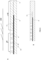
- FIG 1 shows a schematic perspective view of a prototype of the cold plasma device.
- Figure 2 shows the device of Figure 1 in schematic cross sectional view.
- Figure 3 shows an edge detail of the cross sectional view in Figure 2 .
- the plasma device 100 provides a dielectric barrier discharge (DBD) technique for plasma plaster development.
- DBD dielectric barrier discharge
- a DBD type of plasma source has a planar electrode 20 that is covered with a dielectric foil or film 50.
- a gas (or air) gap is present in a compartment 30 formed between an object to be treated (e.g. foot) being functioning as electrode 200 and dielectric 50 with a dielectric constant e.g. larger than 2.
- object to be treated 200 is shown apart from device 100, but in use, edge 40 firmly contacts object 200.
- the electrode 20 is powered by pulsed or AC high-voltage. Due to the dielectric 50, the electric field is mainly present in the air gap 35 formed by protrusions 300 in the structured surface 30.
- the protrusions 300 ensure a minimum distance of the electrode 20 to the object 200 e.g. larger than 1mm. If the electric field is high enough (>30 kV/cm) and if the thickness of the air gap is rather constant, homogeneous cold plasma is created in the air gap to the object to be treated (e.g. the skin of a foot). Dielectric and protrusions have a high dielectric strength, e.g. > 180 kV/mm.
- a DBD cold plasma device can treat large areas; the dimensions of the DBD can be chosen over wide margins. Instead of allowing for airflow between the cold plasma device and the skin, discrete compartments 30 are formed that will contain some air, but these need not be connected to each other, they are isolated from each other, and also isolated to the surroundings by a closed edge.
- the advantage is that the reactive gases that we will generate during operation of the cold plasma, gases like ozone cannot escape. This has the advantage that the device is more efficient: all reactive specimens are available to kill pathogens, and that the release of any toxic gases like ozone will be minimized.
- the compartments can have any shape as long as they are separated from each other, and also they may vary in size and shape, even within one device. Also, each device will have a closed edge in order to prevent release of any gases to the surroundings.
- the device can have any shape, round square, irregularly shaped, and have an edge (typically 1 cm) as described earlier.
- an electrode arrangement 100 is shown for a dielectric barrier discharge plasma treatment of an irregularly three-dimensionally shaped surface of an electrically conducting body.
- the body is typically a human body part, such as a foot, heel, toe, finger or any other diseased skin part, which surface is used as a counter electrode.
- the arrangement has a first planar electrode 20 to be coupled to a high voltage source a dielectric 50 (see Figure 3 ) which is formed by a flexible material in such a way that the dielectric 50 shields the first planar electrode from the surface to be treated; a spacer structure 30 defining a structured surface on a side of said arrangement 100 facing a surface 200 to be treated, such that the structured surface forms one or more spaced compartments 30 that are isolated by an edge 40 from the surroundings in order to prevent airflow between the surroundings and the compartments 30.
- the device 100 has a an electrode 20 that is fitted to the object to be treated 200 and brought in contact with the dielectric, in order to provide a substantially conformal compartment that follows the contours of the 3D shaped body for providing a homogenous microdischarged plasma.
- an electrode 20 fitted to the object to be treated the occurrence of saddle points or sharp folds prevents undesired local field strengths. It may be desirable to shape the electrode centrally to a concave or convex form of the surface to be treated, to optimize the local stretch of the electrode 20, so that the device optimally adapts to the object 200.
- the first planar electrode is a mesh.
- a mesh is suitably adaptable to the 3D shape, and will not rupture, crease or fold.
- the mesh may be contacted by a twisted pair lead 23, that connects to a high voltage clamp 25, and a ground electrode clamp 26 that connects to the second electrode respectively, said lead integrated in lead portion 45 integral to the edge 40. It was found that a mesh is stretchably deformable around three dimensional of an object to be treated, such as a heel, finger or toe, while still being able to provide a suitable homogenous plasma. It will be understood that 'stretchable' is to be understood in a conventional context known to the skilled person, i.e.
- the structured surface comprises an edge portion 40 wherein the first planar electrode 20 extends into the edge portion 40.
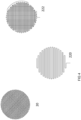
- Figure 4 shows a variety of electrode structures 20, 220 and 222. It is shown that the mesh may be provided by woven conductive threads, typically metallic, with a weave that allows in plane deformations. In contrast to electrode 20, that has a weave with straight non-connected parallel wires, electrode structure 220 by forming the first electrode from a continuous conductive wire. In this embodiment, a weave from a single wire, or from wires with a non-intersecting meandering pattern, further prevents breakthrough problems. In another electrode weave 222, the wire is provided with a in intersecting meandering weave pattern.
- the plasma can be powered by repetitive, short high-voltage pulses (ns- ⁇ s duration, up to a few 100 kHz repetition rate).
- a driver circuit 600 is provided for driving the planar electrode, wherein the driver circuit drives the planar electrode in a pulsed voltage in a range of 3-8kV, in a range of 0.5-100kHz, and a pulse duration in a range of 1-150 micro second.
- This allows for a pulse rate that substantially provides a micro discharge wherein electrical current through the object to be treated (skin, human body) will only flow during the time that the plasma is on (which is typically equal to the HV pulse duration).
- the plasma In between the pulses, the plasma is not active, and no current flows through the skin.
- the plasma would be powered by AC voltage, current flow happens during the entire AC cycle, while the plasma is active only during a small part of the AC cycle.
- the pulsed operation of the plasma enables perfect control over the power of the plasma by means of the pulse repetition rate. In this way, the plasma power can be controlled and adjusted without affecting the plasma properties.
- controlling the power is only possible by means of the voltage magnitude, and thus affects the plasma properties.
- Pulse sequences can be optimized towards a specific application.
- the grounded electrode 26 as shown in Figure 1 will enhance safety (prevents plasma generation and/or high-voltage to be present outside of the device), and also reduces electromagnetic emission of the device. This allows the device to be used without problems in any (electrical) environment.
- Figure 5 shows that a second planar electrode 261 completely covers said stretchable isolating cover layer.
- the second planar electrode 261 may be connected to the ground electrode 26.
- the second planar electrode 261 is furthermore connected to conductive ring electrode 260 that is provided in the edge portion.
- This conductive ring electrode may be formed with a conductive sticker edge that is attachable to the human skin.
- 3D convex forms such as a heel portion
- Figure 6 provides a schematic cross sectional view of the embodiment of Figure 5 .
- a (rather) constant width of the gas gap (up to a few mm) is required.
- a structured interface is provided (see figure 2 ) that provides a constant distance between the dielectric barrier and the object to be treated. This is an essential condition for the proper functioning of a DBD device.
- This can be even better accomplished by a dielectric 50 that is formed by a stack 500 of dielectric layers 50.
- a stack 500 of one or more thin foil dielectrics has a possibility to prevent any pinholes that would form an unshielded channel between the electrode and the grounded treatment surface, without any dielectric. This improves the homogeneity of the electric field and corresponding plasma forming.
- Figure 7 shows a further embodiment wherein the conductive ring 260 has an extending lip designed to slightly press into a skin portion for further ensuring grounding of the conductive ring 260.
- the device is provided with an interface 36 layer (See Figure 8 ) between the plasma electrode stack (including dielectric) 500 and the object to be treated so that the gas environment in which the plasma is generated can be tailored (and thus the plasma properties can be tailored) and that provides a constant distance to the object to be treated.
- an interface 36 layer See Figure 8
- the interface 36 may have a controlled composition of gases that in combination with HV driver settings will generate a tailor-made mixture of reactive gases. Also, this layer can act as absorber for e.g. unwanted O3.
- the function of 36 is threefold:
- the properties of the cold plasma depend on the type of gas that is present in the gas gap.
- the interface 36 between the plasma electrodes and the object to be treated allows buffering or storage of gas and the (triggered) slow release of gas during the time that the plasma is running. So the gas environment in which the plasma is generated can be tailored, without the need for gas bottles and associated tubing and flow control. Thus also the plasma properties can be tailored.
- the device can for example be integrated in a mold or plaster that fits to the part of the body that must be treated.
- Such assemblies can be made patient specific, and can be used during the entire treatment period of the patient.
- the interface layer 36 may be constructed as an integral part of a patient specific plasma device, which simultaneously is designed to create an air gap.
- the interface layer can also be a separate device that will be applied temporarily, e.g. in the form of a disposable. Before use, the disposable can be kept in a closed or sealed package or bag. It can be thrown away after use. Storing the disposable into a sealed package allows it to keep it sterile. So there is no need to clean the interface before use.
- a sealed package can also be filled with a preferred gas, thus supporting the buffering of gas in the interface.
- the interface layer 36 of the plasma device 100 Several options are available to construct the interface layer 36 of the plasma device 100.
- One option is to use a (thin) layer of silica aerogel material 36.
- Silicon aerogels find application in drug delivery and have good bio-compatibility. Aerogels have the required electrical properties (they also find application as high-voltage insulators), such as a dielectric constant between 2-4 and a high dielectric strength. Due to the high porosity (>85%) and homogeneous feature of aerogels, the generation of plasma is not hampered by such a layer. The high porosity and large surface area (>400 m2/gram) allows buffering and the slow release of gas. This has been demonstrated for hydrogen fuel storage and for drug delivery applications (where the drugs are in solution with CO2 gas).
- gases such as nitrogen, helium, argon and air can be stored without any problem.
- the slow release of gas will start as soon as the device is taken out of its sealed package.
- the gas release rate can be controlled by the aerogel density and surface area. Gas release may also be triggered (e.g. by the intense electric field or the UV emission of the plasma). Accordingly the gas release rate can be affected by the plasma intensity.
- Another option to construct the interface is to use a (thin) layer or a patch of polymer material.
- the polymer material contains gas reservoirs that are loaded with the preferred gas.
- Plasma is generated into these gas reservoirs 300.
- interface layer 36 provides a protrusion structure for forming these reservoirs and ensuring a minimal distance to the skin.
- the plasma products must be released to the object to be treated (skin). This can be done by for instance permeation and/or diffusion through the polymer membrane. Another way is to rupture the polymeric membrane by means of the plasma (e.g. by the UV or by the intense electric field).
- a third option is to use polymeric gas dispenser materials.
- An example is AIBN that can be used to release N2.
- Another example is silver oxide that can be used to release O2.
- Such materials are used for instance as oxygen generator in airplanes or for very fast gas release in airbags.
- gas release is triggered thermally.
- gas release is triggered by the plasma (UV).
- more complex materials such as zeolites, barium peroxide and azides can be used for gas dispenser applications. However, these materials have poor biocompatibility.
- Such an interface layer 36 can be provided by both a so called “dielectric barrier discharge” (DBD), or a surface dielectric barrier discharge (SDBD).
- DBD dielectric barrier discharge
- SDBD surface dielectric barrier discharge
- flexible materials e.g. plastic or synthetic rubber foils/films, metallic foils, conductive fabrics
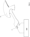
- a flexible construction can be made, that allows to fit the shape of the plasma to the shape of the object to be treated see e.g. Figure 9 , giving an impression how this device can be applied for diabetic foot treatment.
- the electrode form 20 is fitted to the object to be treated by closely following the contour of the heel 200.
- Such electrode form can be integrated into a silicon rubber mould 30 or into a plaster cast, which fits around a heel or toe.
- the electrode may e.g.
- the mesh electrode configuration 20 can be adapted to have a pair of high voltage wire electrodes 20 provided alternating parallel with grounded wiring 25, to create a surface dielectric barrier discharge between adjacent wire electrodes 20, 25.
- remote monitoring e.g. via Internet could be incorporated into the device.
Landscapes
- Health & Medical Sciences (AREA)
- Engineering & Computer Science (AREA)
- Life Sciences & Earth Sciences (AREA)
- Biomedical Technology (AREA)
- Nuclear Medicine, Radiotherapy & Molecular Imaging (AREA)
- Animal Behavior & Ethology (AREA)
- General Health & Medical Sciences (AREA)
- Public Health (AREA)
- Veterinary Medicine (AREA)
- Radiology & Medical Imaging (AREA)
- Physics & Mathematics (AREA)
- Plasma & Fusion (AREA)
- Surgery (AREA)
- Orthopedic Medicine & Surgery (AREA)
- Cell Biology (AREA)
- Spectroscopy & Molecular Physics (AREA)
- Otolaryngology (AREA)
- Heart & Thoracic Surgery (AREA)
- Medical Informatics (AREA)
- Molecular Biology (AREA)
- Plasma Technology (AREA)
- Physical Or Chemical Processes And Apparatus (AREA)
Description
- This invention relates to an electrode arrangement for wound treatment of an irregularly three-dimensionally shaped surface of an electrically conducting body, which surface is used as a counter electrode. In particular, the invention relates to devices that can be applied e.g. for preventing diabetic foot complications.
- Cold plasmas have considerable potential for skin conditioning, disinfection of skin and wound healing. However, available plasma sources lack the possibility to treat larger areas, to control plasma properties and/or the possibility to adapt the shape of the plasma to the shape of the object to be treated (e.g. a foot). This invention focuses on: a cold plasma device, which can treat a larger area.
- Cold plasmas allow efficient, contact-free and painless disinfection, even in microscopic openings, without damaging healthy tissue.
- The bacterial response to plasma application is almost instantaneous (few seconds).
- The plasma is directly in contact with the skin which may result in fast disinfection of the skin.
- When operated in air a high production of NO radicals may be expected. The production of NO might have a positive effect on the microcirculation of blood in the skin, which is very important in the case of diabetic foot.
- A considerable, transient electric field will be present in/near the skin (several kV/cm). Such electrical fields result in faster proliferation of skin cells. Also a positive effect on blood circulation might occur due to electroporation of skin.
- Provides a microbial defense system for plasma application (and hence resistance build- up).
- Plasmas can stimulate human cells without damage. Clinical trials confirm the efficacy and tolerability of plasma in treating infected chronic wounds.
- Plasmas could contribute to a better skin condition and a higher ability for wound healing due to an improved microcirculation.
- Plasma device according to this invention support preventing serious foot complications at an early stage, and contributes to skin improvement, wound prevention and healing.
- Nowadays, the only preventive actions that people with diabetes mellitus can take at home, is daily inspection and daily cleaning of the feet. However, this is often not practical for high-risk patients due to poor eyesight, obesity and stiff joints. World- wide there are no homecare devices available.
- The invention provides an easy to use, fool-proof homecare device that solves this problem.
- Because of the costs involved it is crucial that patients treat their feet every day. However, patients with diabetic foot complications are relatively old and tend to forget.
- The flexible plasma device is a platform technology with a number of interesting applications and market possibilities to improve skin conditions, prevent ulcerations and accelerate healing of the diabetic foot. The plasma can easily be delivered to the skin of a patient, e.g. in the form of a plasma plaster. The skin will be temporary exposed to the plasma to disinfect the skin and to improve cell proliferation and microcirculation of the blood. Typically, one-minute plasma treatment will reduce the bacterial load on the foot with up to a factor of one million, without negatively affecting the skin. Such a treatment should be continued on a once/twice per day basis until the threat of infection has been overcome.
- This technology offers perspectives for medical treatments and prevention measures. In dermatology, new opportunities are being opened for wound healing, tissue regeneration, therapy of skin infections, and probably many more applications. Also, plasmas may effectively kill skin-cancer cells. A few examples:
- Skin diseases: Most dermatological problems are associated with bacterial or fungal infections. Plasmas may help to reduce complications due to bacteria and fungi, and may even treat the diseases themselves.
- Chronic wounds and inflammations: Plasmas may very well assist in controlling the consequences of chronic inflammation associated with these diseases by eliminating bacterial and fungal infections, which results in a drastic improvement of the quality of life.
- Hospital hygiene: The growth of resistant bacteria (e.g. MRSA) poses a big problem in hospitals. Plasma devices can sterilize or disinfect both medical tools and hands (e.g. of surgeons).
- Antifungal treatment: It has been shown that plasmas can be employed efficiently to combat fungal diseases.
- From
US9005188 EP2670477 flexible electrodes are known with a structured surface of a plurality of spaced apart projections from the surface to form air-guiding areas where the plasma is generated. - In summary, embodiments of the invention pertain to: an electrode arrangement according to the features of claim 1.
- The present invention, rather than having a flexible electrode with projections as known from
US9005188 -
-
Figure 1 shows a schematic perspective view of a first embodiment of the cold plasma device; -
Figure 2 shows the device ofFigure 1 in schematic cross sectional view; -
Figure 3A and B show edge details of the cross sectional view inFigure 2 ; -
Figure 4 show various embodiments of the planar electrode of the cold plasma device of the previous Figures; -
Figure 5 shows another embodiment of the cold plasma device; -
Figure 6 provides a schematic cross sectional view of the embodiment ofFigure 5 . -
Figure 7 shows a further embodiment of the cold plasma device; -
Figure 8 shows yet another embodiment of the cold plasma device; -
Figure 9 shows an embodiment of the cold plasma device in use. -
Figure 1 shows a schematic perspective view of a prototype of the cold plasma device.Figure 2 shows the device ofFigure 1 in schematic cross sectional view.Figure 3 shows an edge detail of the cross sectional view inFigure 2 . Theplasma device 100 provides a dielectric barrier discharge (DBD) technique for plasma plaster development. The DBD concept will be briefly explained here with reference toFigure 3 . A DBD type of plasma source has aplanar electrode 20 that is covered with a dielectric foil orfilm 50. A gas (or air) gap is present in acompartment 30 formed between an object to be treated (e.g. foot) being functioning aselectrode 200 and dielectric 50 with a dielectric constant e.g. larger than 2. For ease of understanding inFigure 3A , object to be treated 200 is shown apart fromdevice 100, but in use, edge 40 firmly contacts object 200.Theelectrode 20 is powered by pulsed or AC high-voltage. Due to the dielectric 50, the electric field is mainly present in theair gap 35 formed byprotrusions 300 in the structuredsurface 30. Theprotrusions 300 ensure a minimum distance of theelectrode 20 to theobject 200 e.g. larger than 1mm. If the electric field is high enough (>30 kV/cm) and if the thickness of the air gap is rather constant, homogeneous cold plasma is created in the air gap to the object to be treated (e.g. the skin of a foot). Dielectric and protrusions have a high dielectric strength, e.g. > 180 kV/mm. - A DBD cold plasma device can treat large areas; the dimensions of the DBD can be chosen over wide margins. Instead of allowing for airflow between the cold plasma device and the skin,
discrete compartments 30 are formed that will contain some air, but these need not be connected to each other, they are isolated from each other, and also isolated to the surroundings by a closed edge. - The advantage is that the reactive gases that we will generate during operation of the cold plasma, gases like ozone cannot escape. This has the advantage that the device is more efficient: all reactive specimens are available to kill pathogens, and that the release of any toxic gases like ozone will be minimized.
- Further to this invention, the compartments can have any shape as long as they are separated from each other, and also they may vary in size and shape, even within one device. Also, each device will have a closed edge in order to prevent release of any gases to the surroundings.
- In addition: only with a "closed system" the embodiments as further described will be possible. These inventions include gas control, gas-recipes from within the cold plasma device.
- The device can have any shape, round square, irregularly shaped, and have an edge (typically 1 cm) as described earlier.
- Accordingly an
electrode arrangement 100 is shown for a dielectric barrier discharge plasma treatment of an irregularly three-dimensionally shaped surface of an electrically conducting body. The body is typically a human body part, such as a foot, heel, toe, finger or any other diseased skin part, which surface is used as a counter electrode. The arrangement has a firstplanar electrode 20 to be coupled to a high voltage source a dielectric 50 (seeFigure 3 ) which is formed by a flexible material in such a way that the dielectric 50 shields the first planar electrode from the surface to be treated; aspacer structure 30 defining a structured surface on a side of saidarrangement 100 facing asurface 200 to be treated, such that the structured surface forms one or more spacedcompartments 30 that are isolated by anedge 40 from the surroundings in order to prevent airflow between the surroundings and thecompartments 30. - The
device 100 has a anelectrode 20 that is fitted to the object to be treated 200 and brought in contact with the dielectric, in order to provide a substantially conformal compartment that follows the contours of the 3D shaped body for providing a homogenous microdischarged plasma. By anelectrode 20 fitted to the object to be treated, the occurrence of saddle points or sharp folds prevents undesired local field strengths. It may be desirable to shape the electrode centrally to a concave or convex form of the surface to be treated, to optimize the local stretch of theelectrode 20, so that the device optimally adapts to theobject 200. A particularly suitable embodiment is provided wherein the first planar electrode is a mesh. In contrast to a metal foil, a mesh is suitably adaptable to the 3D shape, and will not rupture, crease or fold. The mesh may be contacted by atwisted pair lead 23, that connects to ahigh voltage clamp 25, and aground electrode clamp 26 that connects to the second electrode respectively, said lead integrated inlead portion 45 integral to theedge 40. It was found that a mesh is stretchably deformable around three dimensional of an object to be treated, such as a heel, finger or toe, while still being able to provide a suitable homogenous plasma. It will be understood that 'stretchable' is to be understood in a conventional context known to the skilled person, i.e. in contrast to merely being flexible but non deformable in a planar length dimension, able to deform in a planar dimension typically more than 2-5% or even 10% of a length dimension. Furthermore, it can be seen that the structured surface comprises anedge portion 40 wherein the firstplanar electrode 20 extends into theedge portion 40. By extending theplanar electrode 20 into the edge portion 40 a suitable solution may be provided for a problem of preventing break through near the edge portion of theelectrode 20. -
Figure 4 shows a variety ofelectrode structures electrode 20, that has a weave with straight non-connected parallel wires,electrode structure 220 by forming the first electrode from a continuous conductive wire. In this embodiment, a weave from a single wire, or from wires with a non-intersecting meandering pattern, further prevents breakthrough problems. In anotherelectrode weave 222, the wire is provided with a in intersecting meandering weave pattern. - Variations to such embodiments, one could have the following additions or changes:
- When the high voltage (HV) connection comes from the side which has the advantage of maximum flexibility, and makes it easier to make the device "see through". In such an embodiment, the first
planar electrode 20 may be contacted with atwisted pair lead 23, that connects tohigh voltage clamp 25, the twisted pair preventing high field strengths outside theplanar electrode 20. Aground electrode clamp 26 connects to thesecond electrode 260 respectively, saidlead 23 integrated in alead portion 45 integral to theedge portion 40. - When the HV connection comes from the rear, has the advantage that the device will be more compact
- The
planar electrode 20 is connected to contact 25 with slide contacts of a PCB connector (not trivial for HV connectors) for easy operation and for costs reduction of the disposable part - The electrode arrangement is substantially transparent, so that an underlying body and the created plasma can be visually inspected. Specifically the dielectric material and the electrode are transparent so that it is possible to see the plasma in operation and to see the area under the plasma device (the wound). More specifically the isolating cover layer and spacer are provided from a single transparent flexible preform, for example, a single transparent isolator that hinges on an edge part 42 (see
Figure 3 ). - The driver circuit may comprise a planar electrode identification circuit. The connector has a sense (or identification) contact (not shown), so that the driving unit can detect:
- what kind of cold plasma device is connected and adjust it settings for currents and HV
- if a cold plasma is connected at all, for safety purposes
- if a cold plasma device is correctly connected, for safety purposes
This can for example be realized by integrating a matching impedance or impedance circuit to the connector so that the impedance is matched to identify the connector.
- The plasma device can be used at various levels in the medical care system: by the patient himself (e.g. as a homecare device), in primary health care (e.g. by a podiatrist or family doctor), in an outpatient clinic, or in a medical centre or hospital.
- The plasma can be powered by repetitive, short high-voltage pulses (ns-µs duration, up to a few 100 kHz repetition rate). For example, in
Figure 5 adriver circuit 600 is provided for driving the planar electrode, wherein the driver circuit drives the planar electrode in a pulsed voltage in a range of 3-8kV, in a range of 0.5-100kHz, and a pulse duration in a range of 1-150 micro second. This allows for a pulse rate that substantially provides a micro discharge wherein electrical current through the object to be treated (skin, human body) will only flow during the time that the plasma is on (which is typically equal to the HV pulse duration). In between the pulses, the plasma is not active, and no current flows through the skin. When the plasma would be powered by AC voltage, current flow happens during the entire AC cycle, while the plasma is active only during a small part of the AC cycle. - The pulsed operation of the plasma enables perfect control over the power of the plasma by means of the pulse repetition rate. In this way, the plasma power can be controlled and adjusted without affecting the plasma properties. When the plasma would be powered by AC voltage, controlling the power is only possible by means of the voltage magnitude, and thus affects the plasma properties.
- Due to the pulsed operation, treatments can be performed at adjustable and controllable pulse sequences, duty cycles and bursts of pulses with varying duration. Pulse sequences can be optimized towards a specific application.
- The grounded
electrode 26 as shown inFigure 1 will enhance safety (prevents plasma generation and/or high-voltage to be present outside of the device), and also reduces electromagnetic emission of the device. This allows the device to be used without problems in any (electrical) environment. - More specifically,
Figure 5 shows that a secondplanar electrode 261 completely covers said stretchable isolating cover layer. The secondplanar electrode 261 may be connected to theground electrode 26. The secondplanar electrode 261 is furthermore connected toconductive ring electrode 260 that is provided in the edge portion. This conductive ring electrode may be formed with a conductive sticker edge that is attachable to the human skin. For a more precise attachment to 3D convex forms, such as a heel portion, it may be preferred that (parts of) the edge portion are non-stretchable. This may be important for the homogeneity of the electric field and corresponding plasma forming. -
Figure 6 provides a schematic cross sectional view of the embodiment ofFigure 5 . For homogeneous plasma generation, a (rather) constant width of the gas gap (up to a few mm) is required. In this invention, a structured interface is provided (seefigure 2 ) that provides a constant distance between the dielectric barrier and the object to be treated. This is an essential condition for the proper functioning of a DBD device. This can be even better accomplished by a dielectric 50 that is formed by astack 500 of dielectric layers 50. Astack 500 of one or more thin foil dielectrics has a possibility to prevent any pinholes that would form an unshielded channel between the electrode and the grounded treatment surface, without any dielectric. This improves the homogeneity of the electric field and corresponding plasma forming. -
Figure 7 shows a further embodiment wherein theconductive ring 260 has an extending lip designed to slightly press into a skin portion for further ensuring grounding of theconductive ring 260. - In a further embodiment, the device is provided with an
interface 36 layer (SeeFigure 8 ) between the plasma electrode stack (including dielectric) 500 and the object to be treated so that the gas environment in which the plasma is generated can be tailored (and thus the plasma properties can be tailored) and that provides a constant distance to the object to be treated. Such a feature may solve a problem of gas control and may provide a specific form of plasma delivery in the form of tailor made 'plasma-recipes' via a gas composition that becomes available when the device is activated. Theinterface 36 may have a controlled composition of gases that in combination with HV driver settings will generate a tailor-made mixture of reactive gases. Also, this layer can act as absorber for e.g. unwanted O3. In short, the function of 36 is threefold: - 1) Define the gas mixture (O2, N2, H2O, others) in the plasma, and steer the properties of the plasma,
- 2) Absorb unwanted gases, and
- 3) Set the distance between electrode and skin/human.
- The properties of the cold plasma (such as the yields of reactive species and UV) depend on the type of gas that is present in the gas gap. The
interface 36 between the plasma electrodes and the object to be treated allows buffering or storage of gas and the (triggered) slow release of gas during the time that the plasma is running. So the gas environment in which the plasma is generated can be tailored, without the need for gas bottles and associated tubing and flow control. Thus also the plasma properties can be tailored. - From an application point of view, the device can for example be integrated in a mold or plaster that fits to the part of the body that must be treated. Such assemblies can be made patient specific, and can be used during the entire treatment period of the patient.
- The
interface layer 36 may be constructed as an integral part of a patient specific plasma device, which simultaneously is designed to create an air gap. Alternatively the interface layer can also be a separate device that will be applied temporarily, e.g. in the form of a disposable. Before use, the disposable can be kept in a closed or sealed package or bag. It can be thrown away after use. Storing the disposable into a sealed package allows it to keep it sterile. So there is no need to clean the interface before use. A sealed package can also be filled with a preferred gas, thus supporting the buffering of gas in the interface. - Several options are available to construct the
interface layer 36 of theplasma device 100. One option is to use a (thin) layer ofsilica aerogel material 36. Silicon aerogels find application in drug delivery and have good bio-compatibility. Aerogels have the required electrical properties (they also find application as high-voltage insulators), such as a dielectric constant between 2-4 and a high dielectric strength. Due to the high porosity (>85%) and homogeneous feature of aerogels, the generation of plasma is not hampered by such a layer. The high porosity and large surface area (>400 m2/gram) allows buffering and the slow release of gas. This has been demonstrated for hydrogen fuel storage and for drug delivery applications (where the drugs are in solution with CO2 gas). It is expected that gases such as nitrogen, helium, argon and air can be stored without any problem. The slow release of gas will start as soon as the device is taken out of its sealed package. The gas release rate can be controlled by the aerogel density and surface area. Gas release may also be triggered (e.g. by the intense electric field or the UV emission of the plasma). Accordingly the gas release rate can be affected by the plasma intensity. - Another option to construct the interface is to use a (thin) layer or a patch of polymer material. The polymer material contains gas reservoirs that are loaded with the preferred gas.
- Plasma is generated into these
gas reservoirs 300. Optionally,interface layer 36 provides a protrusion structure for forming these reservoirs and ensuring a minimal distance to the skin. The plasma products must be released to the object to be treated (skin). This can be done by for instance permeation and/or diffusion through the polymer membrane. Another way is to rupture the polymeric membrane by means of the plasma (e.g. by the UV or by the intense electric field). - A third option is to use polymeric gas dispenser materials. An example is AIBN that can be used to release N2. Another example is silver oxide that can be used to release O2. Such materials are used for instance as oxygen generator in airplanes or for very fast gas release in airbags. Generally, gas release is triggered thermally. Preferably gas release is triggered by the plasma (UV). Also more complex materials, such as zeolites, barium peroxide and azides can be used for gas dispenser applications. However, these materials have poor biocompatibility.
- Important features of the device as in
Figure 8 are: - The gas environment in which the plasma is generated can be tailored, without the need for gas bottles and associated tubing and flow control. Thus also the plasma properties can be tailored towards optimal therapeutic use.
- The pulsed operation of the device allows perfect control over the power of the plasma in order to maximize the treatment efficiency while minimizing negative effects of a too high power. Treatment "protocols" can be developed and optimized (even patient specific).
- Such an
interface layer 36 can be provided by both a so called "dielectric barrier discharge" (DBD), or a surface dielectric barrier discharge (SDBD). By applying flexible materials (e.g. plastic or synthetic rubber foils/films, metallic foils, conductive fabrics) a flexible construction can be made, that allows to fit the shape of the plasma to the shape of the object to be treated see e.g.Figure 9 , giving an impression how this device can be applied for diabetic foot treatment. E.g. theelectrode form 20 is fitted to the object to be treated by closely following the contour of theheel 200. Such electrode form can be integrated into asilicon rubber mould 30 or into a plaster cast, which fits around a heel or toe. The electrode may e.g. have adielectric coating 50 and can be of the stretchable mesh type as illustrated inFigure 4 , e.g. woven from a singlecontinuous wire 20. In some embodiments, themesh electrode configuration 20 can be adapted to have a pair of highvoltage wire electrodes 20 provided alternating parallel with groundedwiring 25, to create a surface dielectric barrier discharge betweenadjacent wire electrodes - To stimulate compliance, remote monitoring e.g. via Internet could be incorporated into the device.
Claims (15)
- An electrode arrangement (100) for wound treatment of an irregularly three-dimensionally shaped surface of an electrically conducting body (200), which surface is used as a counter electrode, having- a first planar electrode (20) to be coupled to a high voltage source which planar electrode (20) is covered with a dielectric foil or film (50)formed by a flexible material in such a way that the dielectric shields the first planar electrode (20) from the surface to be treated;- a spacer (30) defining a structured surface on a side of said arrangement facing a surface to be treated, such that the structured surface forms one or more spaced compartments (30) that are isolated from each other by protrusions (300) ensuring a minimum distance of the electrode (20) to the object; and are isolated from the surrounding of the compartments by an edge (40) in order to prevent airflow between the surrounding and the compartments (30),- said first planar electrode (20) being fitted to the object to be treated (200) and brought in contact with the dielectric, and- an isolating cover layer covering the first planar electrode (20).
- The electrode arrangement, according to claim 1, wherein the dielectric is formed by a stack (500) of dielectric layers.
- The electrode arrangement, according to any of the previous claims, wherein the structured surface comprises an edge portion (40) wherein the first planar electrode (20) extends into the edge portion (40).
- The electrode arrangement of claim 3, wherein the edge portion (40) is non-stretchable.
- The electrode arrangement of any of the previous claims, wherein the first planar electrode (20) is a stretchable mesh.
- The electrode arrangement of any of the previous claims, wherein the first planar electrode (20) is formed from a continuous conductive wire.
- The electrode arrangement of any of the previous claims, wherein the first planar electrode (20) is formed from a conductive wire, that is coated with a dielectric.
- The electrode arrangement of any of the previous claims, wherein the first planar electrode (20) is contacted with a twisted pair lead (23), that connects to a high voltage clamp, and a ground electrode clamp that connects to the second electrode (26) respectively, said lead integrated in a lead portion integral to the edge .
- The electrode arrangement according to any of the previous claims, wherein the electrode arrangement is substantially transparent, so that an underlying body (200) and the created plasma can be visually inspected.
- The electrode arrangement according to any of the preceding claims, wherein the isolating cover layer and spacer (30) are provided from a single transparent flexible preform.
- The electrode arrangement according to any of the preceding claims, wherein the planar electrode is connected to a contact with slide contacts of a PCB connector.
- The electrode arrangement according to any of the preceding claims further comprising a driver circuit for driving the planar electrode coupled to said high voltage source, wherein the driver circuit drives the planar electrode in a pulsed voltage in a range of 3-8kV, repetition rate in a range of 0.5-50kHz, and a pulse duration in a range of 0.1-100 micro second
- The electrode arrangement according to claim 12 wherein the driver circuit comprises a planar electrode identification circuit.
- The electrode arrangement according to any of the preceding claims wherein a further gas control structure is provided in the electrode arrangement, arranged to generate a plasma precursor gas.
- The electrode arrangement of claim 14, wherein the gas control structure comprises a gas drain or gas absorbent.
Applications Claiming Priority (2)
| Application Number | Priority Date | Filing Date | Title |
|---|---|---|---|
| US201562163578P | 2015-05-19 | 2015-05-19 | |
| PCT/NL2016/050359 WO2016186501A2 (en) | 2015-05-19 | 2016-05-19 | Non-thermal plasma device |
Publications (3)
| Publication Number | Publication Date |
|---|---|
| EP3297724A2 EP3297724A2 (en) | 2018-03-28 |
| EP3297724B1 true EP3297724B1 (en) | 2023-08-16 |
| EP3297724C0 EP3297724C0 (en) | 2023-08-16 |
Family
ID=56555689
Family Applications (1)
| Application Number | Title | Priority Date | Filing Date |
|---|---|---|---|
| EP16745197.0A Active EP3297724B1 (en) | 2015-05-19 | 2016-05-19 | Electrode arrangement for wound treatment |
Country Status (3)
| Country | Link |
|---|---|
| US (1) | US20180140824A1 (en) |
| EP (1) | EP3297724B1 (en) |
| WO (1) | WO2016186501A2 (en) |
Families Citing this family (14)
| Publication number | Priority date | Publication date | Assignee | Title |
|---|---|---|---|---|
| WO2017153898A1 (en) * | 2016-03-07 | 2017-09-14 | King Abdullah University Of Science And Technology | Non thermal plasma surface cleaner and method of use |
| DE102017100161B4 (en) * | 2017-01-05 | 2022-08-04 | Cinogy Gmbh | Flat, flexible support piece for dielectric barrier plasma treatment |
| DE102017100192A1 (en) * | 2017-01-06 | 2018-07-12 | Cinogy Gmbh | Permanent wound dressing with plasma electrode |
| DE102017116305A1 (en) | 2017-07-19 | 2019-01-24 | Cinogy Gmbh | Plasma treatment device |
| KR101922507B1 (en) * | 2017-11-29 | 2018-11-28 | 주식회사 서린메디케어 | Skin treatment apparatus using fractional plasma |
| NL2020126B1 (en) * | 2017-12-19 | 2019-06-26 | Plasmacure B V | EMC control for pulsed high voltage source of a plasma device for medical treatment |
| WO2020028420A1 (en) | 2018-07-31 | 2020-02-06 | L'oreal | Generating cold plasma away from skin, and associated systems and methods |
| ES2973082T3 (en) * | 2018-07-31 | 2024-06-18 | Oreal | Cold plasma generation devices and systems |
| NL2021675B1 (en) * | 2018-09-20 | 2020-05-07 | Plasmacure B V | Driver circuit for a dielectric barrier discharge plasma treatment |
| KR102031713B1 (en) * | 2019-01-29 | 2019-10-14 | (주)에스제이글로벌 | Plasma pad of wound area and plasma treatment device |
| DE102019006536B3 (en) * | 2019-09-16 | 2020-12-31 | Blv Licht- Und Vakuumtechnik Gmbh | Device and method for skin and in particular wound treatment using plasma |
| CN111988902B (en) * | 2020-08-14 | 2022-08-05 | 清华大学 | Flexible gasbag formula plasma generator |
| NL2027148B1 (en) * | 2020-12-17 | 2022-07-11 | Plasmacure B V | Treatment pad for a dielectric barrier discharge plasma treatment |
| CN113556855B (en) * | 2021-07-22 | 2022-06-10 | 重庆大学 | Three-electrode double-source excitation plasma generating device |
Family Cites Families (8)
| Publication number | Priority date | Publication date | Assignee | Title |
|---|---|---|---|---|
| US6149620A (en) * | 1995-11-22 | 2000-11-21 | Arthrocare Corporation | System and methods for electrosurgical tissue treatment in the presence of electrically conductive fluid |
| US20030168009A1 (en) * | 2002-03-08 | 2003-09-11 | Denes Ferencz S. | Plasma processing within low-dimension cavities |
| DE102007030915A1 (en) * | 2007-07-03 | 2009-01-22 | Cinogy Gmbh | Device for the treatment of surfaces with a plasma generated by means of an electrode via a solid dielectric by a dielectrically impeded gas discharge |
| DE102009060627B4 (en) * | 2009-12-24 | 2014-06-05 | Cinogy Gmbh | Electrode arrangement for a dielectrically impeded plasma treatment |
| GB201021032D0 (en) * | 2010-12-10 | 2011-01-26 | Creo Medical Ltd | Electrosurgical apparatus |
| WO2012106735A2 (en) | 2011-02-01 | 2012-08-09 | Moe Medical Devices Llc | Plasma-assisted skin treatment |
| EP2760536A4 (en) * | 2011-09-17 | 2015-05-06 | Moe Medical Devices Llc | Systems methods and machine readable programs for electric field and/or plasma-assisted onychomycosis treatment |
| DE102012207750A1 (en) * | 2012-05-09 | 2013-11-28 | Leibniz-Institut für Plasmaforschung und Technologie e.V. | APPARATUS FOR THE PLASMA TREATMENT OF HUMAN, ANIMAL OR VEGETABLE SURFACES, IN PARTICULAR OF SKIN OR TINIAL TIPS |
-
2016
- 2016-05-19 WO PCT/NL2016/050359 patent/WO2016186501A2/en active Application Filing
- 2016-05-19 EP EP16745197.0A patent/EP3297724B1/en active Active
- 2016-05-19 US US15/574,713 patent/US20180140824A1/en active Pending
Also Published As
| Publication number | Publication date |
|---|---|
| WO2016186501A2 (en) | 2016-11-24 |
| EP3297724A2 (en) | 2018-03-28 |
| US20180140824A1 (en) | 2018-05-24 |
| WO2016186501A3 (en) | 2017-03-23 |
| EP3297724C0 (en) | 2023-08-16 |
Similar Documents
| Publication | Publication Date | Title |
|---|---|---|
| EP3297724B1 (en) | Electrode arrangement for wound treatment | |
| EP3541311B1 (en) | Non-therma plasma device with electromagnetic compatibility control | |
| US11006995B2 (en) | Device for the planar treatment of areas of human or animal skin or mucous membrane surfaces by means of a cold atmospheric pressure plasma | |
| JP5319709B2 (en) | Plasma equipment that selectively treats electroporated cells | |
| US11724078B2 (en) | Methods and systems for trans-tissue substance delivery using plasmaporation | |
| US11622439B2 (en) | Apparatus and methods for treatment using non-thermal plasma | |
| US10307606B2 (en) | Device for generating plasma, system for generating plasma and method for generating plasma | |
| CN110404171B (en) | Integrated flexible plasma device for foot dry sterilization | |
| BR112017007257B1 (en) | DEVICE TO PRODUCE A COLD PLASMA AT ATMOSPHERIC PRESSURE FOR THE TREATMENT OF HUMAN AND/OR ANIMAL SURFACES, CABLE TO CONNECT WITH A DEVICE, GENERATING UNIT TO PROVIDE A HIGH VOLTAGE TO PRODUCE A COLD PLASMA AT ATMOSPHERIC PRESSURE WITH A DEVICE, AND SYSTEM | |
| US20160271411A1 (en) | Cold plasma pressure treatment system | |
| US20170050039A1 (en) | Plasma hydrogel therapy | |
| WO2014143412A1 (en) | Method and apparatus for antimicrobial treatment | |
| CN109644547A (en) | Wound dressing | |
| US20230285630A1 (en) | Plasma hydrogel therapy | |
| KR20180073729A (en) | Plasma Emitting Type Skin Treating Apparatus | |
| KR101286272B1 (en) | Medical Device | |
| JP7447290B2 (en) | Medical device and method for producing plasma activated liquid | |
| CN110420387B (en) | Foot dry type sterilization device based on atmospheric pressure flexible low-temperature plasma | |
| US12069793B2 (en) | Treatment of infectious diseases using non-thermal plasma | |
| EP3490668B1 (en) | Apparatus for therapeutic treatment of tissue injuries | |
| CN116114387A (en) | Apparatus and method for inactivating microorganisms using non-thermal plasma | |
| MXPA03009743A (en) | Method and system for electrokinetic delivery of a substance. |
Legal Events
| Date | Code | Title | Description |
|---|---|---|---|
| STAA | Information on the status of an ep patent application or granted ep patent |
Free format text: STATUS: THE INTERNATIONAL PUBLICATION HAS BEEN MADE |
|
| PUAI | Public reference made under article 153(3) epc to a published international application that has entered the european phase |
Free format text: ORIGINAL CODE: 0009012 |
|
| STAA | Information on the status of an ep patent application or granted ep patent |
Free format text: STATUS: REQUEST FOR EXAMINATION WAS MADE |
|
| 17P | Request for examination filed |
Effective date: 20171204 |
|
| AK | Designated contracting states |
Kind code of ref document: A2 Designated state(s): AL AT BE BG CH CY CZ DE DK EE ES FI FR GB GR HR HU IE IS IT LI LT LU LV MC MK MT NL NO PL PT RO RS SE SI SK SM TR |
|
| AX | Request for extension of the european patent |
Extension state: BA ME |
|
| DAV | Request for validation of the european patent (deleted) | ||
| DAX | Request for extension of the european patent (deleted) | ||
| RAP1 | Party data changed (applicant data changed or rights of an application transferred) |
Owner name: PLASMACURE B.V. |
|
| RIN1 | Information on inventor provided before grant (corrected) |
Inventor name: ZEPER, WOUTER BASTIAAN Inventor name: PEMEN, AUGUST JOHANNES MARIE |
|
| STAA | Information on the status of an ep patent application or granted ep patent |
Free format text: STATUS: EXAMINATION IS IN PROGRESS |
|
| 17Q | First examination report despatched |
Effective date: 20220222 |
|
| GRAP | Despatch of communication of intention to grant a patent |
Free format text: ORIGINAL CODE: EPIDOSNIGR1 |
|
| STAA | Information on the status of an ep patent application or granted ep patent |
Free format text: STATUS: GRANT OF PATENT IS INTENDED |
|
| INTG | Intention to grant announced |
Effective date: 20230301 |
|
| GRAS | Grant fee paid |
Free format text: ORIGINAL CODE: EPIDOSNIGR3 |
|
| GRAA | (expected) grant |
Free format text: ORIGINAL CODE: 0009210 |
|
| STAA | Information on the status of an ep patent application or granted ep patent |
Free format text: STATUS: THE PATENT HAS BEEN GRANTED |
|
| AK | Designated contracting states |
Kind code of ref document: B1 Designated state(s): AL AT BE BG CH CY CZ DE DK EE ES FI FR GB GR HR HU IE IS IT LI LT LU LV MC MK MT NL NO PL PT RO RS SE SI SK SM TR |
|
| REG | Reference to a national code |
Ref country code: GB Ref legal event code: FG4D |
|
| REG | Reference to a national code |
Ref country code: CH Ref legal event code: EP Ref country code: DE Ref legal event code: R096 Ref document number: 602016081963 Country of ref document: DE |
|
| REG | Reference to a national code |
Ref country code: IE Ref legal event code: FG4D |
|
| U01 | Request for unitary effect filed |
Effective date: 20230914 |
|
| U07 | Unitary effect registered |
Designated state(s): AT BE BG DE DK EE FI FR IT LT LU LV MT NL PT SE SI Effective date: 20230921 |
|
| PG25 | Lapsed in a contracting state [announced via postgrant information from national office to epo] |
Ref country code: GR Free format text: LAPSE BECAUSE OF FAILURE TO SUBMIT A TRANSLATION OF THE DESCRIPTION OR TO PAY THE FEE WITHIN THE PRESCRIBED TIME-LIMIT Effective date: 20231117 |
|
| PG25 | Lapsed in a contracting state [announced via postgrant information from national office to epo] |
Ref country code: IS Free format text: LAPSE BECAUSE OF FAILURE TO SUBMIT A TRANSLATION OF THE DESCRIPTION OR TO PAY THE FEE WITHIN THE PRESCRIBED TIME-LIMIT Effective date: 20231216 |
|
| PG25 | Lapsed in a contracting state [announced via postgrant information from national office to epo] |
Ref country code: RS Free format text: LAPSE BECAUSE OF FAILURE TO SUBMIT A TRANSLATION OF THE DESCRIPTION OR TO PAY THE FEE WITHIN THE PRESCRIBED TIME-LIMIT Effective date: 20230816 Ref country code: NO Free format text: LAPSE BECAUSE OF FAILURE TO SUBMIT A TRANSLATION OF THE DESCRIPTION OR TO PAY THE FEE WITHIN THE PRESCRIBED TIME-LIMIT Effective date: 20231116 Ref country code: IS Free format text: LAPSE BECAUSE OF FAILURE TO SUBMIT A TRANSLATION OF THE DESCRIPTION OR TO PAY THE FEE WITHIN THE PRESCRIBED TIME-LIMIT Effective date: 20231216 Ref country code: HR Free format text: LAPSE BECAUSE OF FAILURE TO SUBMIT A TRANSLATION OF THE DESCRIPTION OR TO PAY THE FEE WITHIN THE PRESCRIBED TIME-LIMIT Effective date: 20230816 Ref country code: GR Free format text: LAPSE BECAUSE OF FAILURE TO SUBMIT A TRANSLATION OF THE DESCRIPTION OR TO PAY THE FEE WITHIN THE PRESCRIBED TIME-LIMIT Effective date: 20231117 |
|
| PG25 | Lapsed in a contracting state [announced via postgrant information from national office to epo] |
Ref country code: PL Free format text: LAPSE BECAUSE OF FAILURE TO SUBMIT A TRANSLATION OF THE DESCRIPTION OR TO PAY THE FEE WITHIN THE PRESCRIBED TIME-LIMIT Effective date: 20230816 |
|
| U20 | Renewal fee paid [unitary effect] |
Year of fee payment: 9 Effective date: 20240319 |
|
| PG25 | Lapsed in a contracting state [announced via postgrant information from national office to epo] |
Ref country code: ES Free format text: LAPSE BECAUSE OF FAILURE TO SUBMIT A TRANSLATION OF THE DESCRIPTION OR TO PAY THE FEE WITHIN THE PRESCRIBED TIME-LIMIT Effective date: 20230816 |
|
| PG25 | Lapsed in a contracting state [announced via postgrant information from national office to epo] |
Ref country code: SM Free format text: LAPSE BECAUSE OF FAILURE TO SUBMIT A TRANSLATION OF THE DESCRIPTION OR TO PAY THE FEE WITHIN THE PRESCRIBED TIME-LIMIT Effective date: 20230816 Ref country code: RO Free format text: LAPSE BECAUSE OF FAILURE TO SUBMIT A TRANSLATION OF THE DESCRIPTION OR TO PAY THE FEE WITHIN THE PRESCRIBED TIME-LIMIT Effective date: 20230816 Ref country code: ES Free format text: LAPSE BECAUSE OF FAILURE TO SUBMIT A TRANSLATION OF THE DESCRIPTION OR TO PAY THE FEE WITHIN THE PRESCRIBED TIME-LIMIT Effective date: 20230816 Ref country code: CZ Free format text: LAPSE BECAUSE OF FAILURE TO SUBMIT A TRANSLATION OF THE DESCRIPTION OR TO PAY THE FEE WITHIN THE PRESCRIBED TIME-LIMIT Effective date: 20230816 Ref country code: SK Free format text: LAPSE BECAUSE OF FAILURE TO SUBMIT A TRANSLATION OF THE DESCRIPTION OR TO PAY THE FEE WITHIN THE PRESCRIBED TIME-LIMIT Effective date: 20230816 |
|
| REG | Reference to a national code |
Ref country code: DE Ref legal event code: R097 Ref document number: 602016081963 Country of ref document: DE |
|
| PGFP | Annual fee paid to national office [announced via postgrant information from national office to epo] |
Ref country code: GB Payment date: 20240521 Year of fee payment: 9 |
|
| 26N | No opposition filed |
Effective date: 20240517 |