EP3297719B1 - Detection of lead orientation - Google Patents
Detection of lead orientation Download PDFInfo
- Publication number
- EP3297719B1 EP3297719B1 EP16766147.9A EP16766147A EP3297719B1 EP 3297719 B1 EP3297719 B1 EP 3297719B1 EP 16766147 A EP16766147 A EP 16766147A EP 3297719 B1 EP3297719 B1 EP 3297719B1
- Authority
- EP
- European Patent Office
- Prior art keywords
- lead
- marker
- circuit
- direction vector
- template
- Prior art date
- Legal status (The legal status is an assumption and is not a legal conclusion. Google has not performed a legal analysis and makes no representation as to the accuracy of the status listed.)
- Active
Links
- 238000001514 detection method Methods 0.000 title description 2
- 239000003550 marker Substances 0.000 claims description 218
- 239000013598 vector Substances 0.000 claims description 107
- 230000009466 transformation Effects 0.000 claims description 41
- 238000002591 computed tomography Methods 0.000 claims description 27
- 238000003384 imaging method Methods 0.000 claims description 18
- 230000015572 biosynthetic process Effects 0.000 claims description 17
- PXFBZOLANLWPMH-UHFFFAOYSA-N 16-Epiaffinine Natural products C1C(C2=CC=CC=C2N2)=C2C(=O)CC2C(=CC)CN(C)C1C2CO PXFBZOLANLWPMH-UHFFFAOYSA-N 0.000 claims description 4
- 230000001131 transforming effect Effects 0.000 claims description 3
- 238000000034 method Methods 0.000 description 39
- 230000004007 neuromodulation Effects 0.000 description 25
- WABPQHHGFIMREM-NOHWODKXSA-N lead-200 Chemical compound [200Pb] WABPQHHGFIMREM-NOHWODKXSA-N 0.000 description 19
- 230000015654 memory Effects 0.000 description 18
- 230000000638 stimulation Effects 0.000 description 16
- 238000004891 communication Methods 0.000 description 14
- 210000001519 tissue Anatomy 0.000 description 13
- 238000003860 storage Methods 0.000 description 9
- 230000006870 function Effects 0.000 description 8
- 230000001537 neural effect Effects 0.000 description 8
- 238000002560 therapeutic procedure Methods 0.000 description 8
- 210000003484 anatomy Anatomy 0.000 description 6
- 230000004927 fusion Effects 0.000 description 5
- 230000005291 magnetic effect Effects 0.000 description 5
- 239000002858 neurotransmitter agent Substances 0.000 description 5
- 238000000844 transformation Methods 0.000 description 5
- 210000004556 brain Anatomy 0.000 description 4
- 238000003709 image segmentation Methods 0.000 description 4
- 238000005304 joining Methods 0.000 description 4
- 238000002595 magnetic resonance imaging Methods 0.000 description 4
- 210000000278 spinal cord Anatomy 0.000 description 4
- 230000005540 biological transmission Effects 0.000 description 3
- 239000004020 conductor Substances 0.000 description 3
- 238000010276 construction Methods 0.000 description 3
- 238000004519 manufacturing process Methods 0.000 description 3
- 238000012952 Resampling Methods 0.000 description 2
- 230000004913 activation Effects 0.000 description 2
- 238000012512 characterization method Methods 0.000 description 2
- 239000003795 chemical substances by application Substances 0.000 description 2
- 238000000354 decomposition reaction Methods 0.000 description 2
- 230000000694 effects Effects 0.000 description 2
- 230000001939 inductive effect Effects 0.000 description 2
- 230000003993 interaction Effects 0.000 description 2
- 238000007726 management method Methods 0.000 description 2
- 230000000877 morphologic effect Effects 0.000 description 2
- 238000003062 neural network model Methods 0.000 description 2
- 230000003287 optical effect Effects 0.000 description 2
- 238000005192 partition Methods 0.000 description 2
- 210000000578 peripheral nerve Anatomy 0.000 description 2
- 238000002600 positron emission tomography Methods 0.000 description 2
- 230000008569 process Effects 0.000 description 2
- 238000002603 single-photon emission computed tomography Methods 0.000 description 2
- 230000004936 stimulating effect Effects 0.000 description 2
- 238000013519 translation Methods 0.000 description 2
- 238000012384 transportation and delivery Methods 0.000 description 2
- 238000012935 Averaging Methods 0.000 description 1
- 239000011248 coating agent Substances 0.000 description 1
- 238000000576 coating method Methods 0.000 description 1
- 150000001875 compounds Chemical class 0.000 description 1
- 238000004590 computer program Methods 0.000 description 1
- 238000003066 decision tree Methods 0.000 description 1
- 230000001419 dependent effect Effects 0.000 description 1
- 238000003745 diagnosis Methods 0.000 description 1
- 238000002059 diagnostic imaging Methods 0.000 description 1
- 238000002405 diagnostic procedure Methods 0.000 description 1
- 238000010586 diagram Methods 0.000 description 1
- 238000009826 distribution Methods 0.000 description 1
- 238000005265 energy consumption Methods 0.000 description 1
- 238000001914 filtration Methods 0.000 description 1
- 238000009472 formulation Methods 0.000 description 1
- 230000007274 generation of a signal involved in cell-cell signaling Effects 0.000 description 1
- 239000000463 material Substances 0.000 description 1
- 239000002184 metal Substances 0.000 description 1
- 239000000203 mixture Substances 0.000 description 1
- 210000005036 nerve Anatomy 0.000 description 1
- 230000007383 nerve stimulation Effects 0.000 description 1
- 210000000653 nervous system Anatomy 0.000 description 1
- 230000007935 neutral effect Effects 0.000 description 1
- 230000002093 peripheral effect Effects 0.000 description 1
- 238000013439 planning Methods 0.000 description 1
- 238000005070 sampling Methods 0.000 description 1
- 230000011218 segmentation Effects 0.000 description 1
- 239000004065 semiconductor Substances 0.000 description 1
- 210000003594 spinal ganglia Anatomy 0.000 description 1
- 210000000273 spinal nerve root Anatomy 0.000 description 1
- 238000007920 subcutaneous administration Methods 0.000 description 1
- 238000012706 support-vector machine Methods 0.000 description 1
- 230000001225 therapeutic effect Effects 0.000 description 1
- 238000003325 tomography Methods 0.000 description 1
- 238000012546 transfer Methods 0.000 description 1
- 238000002604 ultrasonography Methods 0.000 description 1
- 238000012800 visualization Methods 0.000 description 1
Images


Classifications
-
- A—HUMAN NECESSITIES
- A61—MEDICAL OR VETERINARY SCIENCE; HYGIENE
- A61N—ELECTROTHERAPY; MAGNETOTHERAPY; RADIATION THERAPY; ULTRASOUND THERAPY
- A61N1/00—Electrotherapy; Circuits therefor
- A61N1/18—Applying electric currents by contact electrodes
- A61N1/32—Applying electric currents by contact electrodes alternating or intermittent currents
- A61N1/36—Applying electric currents by contact electrodes alternating or intermittent currents for stimulation
- A61N1/372—Arrangements in connection with the implantation of stimulators
- A61N1/37211—Means for communicating with stimulators
- A61N1/37217—Means for communicating with stimulators characterised by the communication link, e.g. acoustic or tactile
-
- A—HUMAN NECESSITIES
- A61—MEDICAL OR VETERINARY SCIENCE; HYGIENE
- A61B—DIAGNOSIS; SURGERY; IDENTIFICATION
- A61B6/00—Apparatus for radiation diagnosis, e.g. combined with radiation therapy equipment
- A61B6/12—Devices for detecting or locating foreign bodies
-
- A—HUMAN NECESSITIES
- A61—MEDICAL OR VETERINARY SCIENCE; HYGIENE
- A61N—ELECTROTHERAPY; MAGNETOTHERAPY; RADIATION THERAPY; ULTRASOUND THERAPY
- A61N1/00—Electrotherapy; Circuits therefor
- A61N1/02—Details
- A61N1/04—Electrodes
- A61N1/05—Electrodes for implantation or insertion into the body, e.g. heart electrode
- A61N1/0526—Head electrodes
- A61N1/0529—Electrodes for brain stimulation
- A61N1/0534—Electrodes for deep brain stimulation
-
- A—HUMAN NECESSITIES
- A61—MEDICAL OR VETERINARY SCIENCE; HYGIENE
- A61N—ELECTROTHERAPY; MAGNETOTHERAPY; RADIATION THERAPY; ULTRASOUND THERAPY
- A61N1/00—Electrotherapy; Circuits therefor
- A61N1/18—Applying electric currents by contact electrodes
- A61N1/32—Applying electric currents by contact electrodes alternating or intermittent currents
- A61N1/36—Applying electric currents by contact electrodes alternating or intermittent currents for stimulation
- A61N1/3605—Implantable neurostimulators for stimulating central or peripheral nerve system
-
- A—HUMAN NECESSITIES
- A61—MEDICAL OR VETERINARY SCIENCE; HYGIENE
- A61N—ELECTROTHERAPY; MAGNETOTHERAPY; RADIATION THERAPY; ULTRASOUND THERAPY
- A61N1/00—Electrotherapy; Circuits therefor
- A61N1/18—Applying electric currents by contact electrodes
- A61N1/32—Applying electric currents by contact electrodes alternating or intermittent currents
- A61N1/36—Applying electric currents by contact electrodes alternating or intermittent currents for stimulation
- A61N1/372—Arrangements in connection with the implantation of stimulators
- A61N1/37211—Means for communicating with stimulators
- A61N1/37235—Aspects of the external programmer
- A61N1/37247—User interfaces, e.g. input or presentation means
-
- G—PHYSICS
- G06—COMPUTING; CALCULATING OR COUNTING
- G06T—IMAGE DATA PROCESSING OR GENERATION, IN GENERAL
- G06T7/00—Image analysis
- G06T7/70—Determining position or orientation of objects or cameras
- G06T7/73—Determining position or orientation of objects or cameras using feature-based methods
- G06T7/74—Determining position or orientation of objects or cameras using feature-based methods involving reference images or patches
-
- A—HUMAN NECESSITIES
- A61—MEDICAL OR VETERINARY SCIENCE; HYGIENE
- A61B—DIAGNOSIS; SURGERY; IDENTIFICATION
- A61B90/00—Instruments, implements or accessories specially adapted for surgery or diagnosis and not covered by any of the groups A61B1/00 - A61B50/00, e.g. for luxation treatment or for protecting wound edges
- A61B90/39—Markers, e.g. radio-opaque or breast lesions markers
- A61B2090/3966—Radiopaque markers visible in an X-ray image
-
- A—HUMAN NECESSITIES
- A61—MEDICAL OR VETERINARY SCIENCE; HYGIENE
- A61B—DIAGNOSIS; SURGERY; IDENTIFICATION
- A61B6/00—Apparatus for radiation diagnosis, e.g. combined with radiation therapy equipment
- A61B6/02—Devices for diagnosis sequentially in different planes; Stereoscopic radiation diagnosis
- A61B6/03—Computerised tomographs
- A61B6/032—Transmission computed tomography [CT]
-
- A—HUMAN NECESSITIES
- A61—MEDICAL OR VETERINARY SCIENCE; HYGIENE
- A61N—ELECTROTHERAPY; MAGNETOTHERAPY; RADIATION THERAPY; ULTRASOUND THERAPY
- A61N1/00—Electrotherapy; Circuits therefor
- A61N1/02—Details
- A61N1/04—Electrodes
- A61N1/05—Electrodes for implantation or insertion into the body, e.g. heart electrode
-
- G—PHYSICS
- G06—COMPUTING; CALCULATING OR COUNTING
- G06T—IMAGE DATA PROCESSING OR GENERATION, IN GENERAL
- G06T2207/00—Indexing scheme for image analysis or image enhancement
- G06T2207/10—Image acquisition modality
- G06T2207/10072—Tomographic images
-
- G—PHYSICS
- G06—COMPUTING; CALCULATING OR COUNTING
- G06T—IMAGE DATA PROCESSING OR GENERATION, IN GENERAL
- G06T2207/00—Indexing scheme for image analysis or image enhancement
- G06T2207/30—Subject of image; Context of image processing
- G06T2207/30004—Biomedical image processing
- G06T2207/30021—Catheter; Guide wire
Definitions
- This document relates generally to medical devices for detecting an orientation of a lead.
- Neuromodulation also referred to as neurostimulation
- neurostimulation has been proposed as a therapy for a number of conditions.
- Examples of neuromodulation include Spinal Cord Stimulation (SCS), Deep Brain Stimulation (DBS), Peripheral Nerve Stimulation (PNS), and Functional Electrical Stimulation (FES).
- SCS Spinal Cord Stimulation
- DBS Deep Brain Stimulation
- PNS Peripheral Nerve Stimulation
- FES Functional Electrical Stimulation
- Implantable neuromodulation systems have been applied to deliver such a therapy.
- An implantable neuromodulation system may include an implantable neuromodulator, also referred to as an implantable pulse generator, and one or more implantable leads each including one or more electrodes.
- the implantable neuromodulator may deliver neuromodulation energy through one or more electrodes placed on or near a target neural tissue.
- An external programming device may be used to program the implantable neuromodulator with parameters controlling the delivery of the neuromodulation energy.
- WO2009/139917 discloses a system and method for displaying a volume of activation (VOA) which may include a processor that displays via a display device a model of a portion of a patient anatomy that includes anatomical structures, displays via the display device and overlying the display of the model a VOA associated by the processor with a set of anatomical stimulation parameter settings, the display of the VOA, and graphically identifies interactions between the displayed VOA and a first subset of the anatomical structures associated with one or more stimulation benefits and a second subset of the anatomical structures associated with one or more stimulation side effects, where the graphical identifications differ depending on whether the interaction is with the first subset or the second subset.
- VOA volume of activation
- a method can include storing tracking data in memory, the tracking data being generated by a tracking system to represent a location of an object in a tracking coordinate system of the tracking system.
- the method can also include storing a patient-specific implicit model in memory, the patient-specific implicit model being generated based on image data acquired for the patient to define geometry of an anatomical structure of the patient.
- the method can also include registering the tracking data and the patient-specific implicit model in a common three-dimensional coordinate system.
- the method can also include generating an output visualization representing a location of the object relative to the geometry of the anatomical structure of the patient in the common coordinate system.
- Efficacy and efficiency of certain neuromodulation therapies may be affected by the position and/or orientation of the implantable leads. Proper lead direction and orientation may allow the lead to be used to more accurately target tissue that is desired to be modulated while avoiding or reducing undesirable side-effects caused by unintentionally modulating neighboring cell populations next to or around the target neural structures. Additionally, an improved lead position and/or orientation may also reduce energy consumption and thereby extending longevity of the implantable neuromodulator.
- Some neuromodulation systems may include leads that have a large number of electrodes for stimulating neural targets.
- a neuromodulation lead may have a complex arrangement of multiple electrodes that are not only distributed axially along the leads, but also distributed circumferentially around the lead.
- Such a lead also known as a directional lead, presents a multitude of selections of stimulation parameter sets to the clinician.
- Selection of the electrodes on a lead to be active and programming neuromodulation using the selected electrodes may be complicated and time consuming.
- Diagnostic imaging equipment may be used to localize circumferential locations of the electrodes in the operating room or during follow-up, an orientation of the lead may be determined with respect to an imaging axis of the diagnostic equipment.
- Conventional lead location methods may be used to identify longitudinal contacts of column electrodes (also known as ring electrodes) along the length of the lead relative to a neural target. However, such conventional lead location methods may not provide adequate information about the rotational orientation of the lead.
- the present subject matter effectively and efficiently determines an orientation of a lead to facilitate electrode selection and programming of the neuromodulation system.
- the system may receive image data of at least a portion of the lead including image data of a marker configured to identify a rotational orientation of the lead.
- the system may receive at least one template of the lead having a specified rotational orientation.
- Each template may include a reference data cube and a reference marker direction vector.
- the system may generate a target data cube of the marker using the image data of the marker, and register the reference data cube to the target data cube to produce a transformation operator.
- the system may estimate the rotational orientation of the lead using the reference marker direction vector and the determined transformation operator.
- Various examples disclosed herein include also further systems, devices, and methods for determining a rotational orientation of a lead for use in electrostimulation of a body tissue.
- Image data of at least a portion of the lead including image data of a marker configured to identify a rotational orientation of the lead, may be used to estimate the lead orientation.
- a system may receive at least one template of the lead having a specified rotational orientation.
- Each template may include a reference data cube and a reference marker direction vector.
- the system may generate a target data cube of the marker using the image data of the marker, and register the reference data cube to the target data cube to produce a spatial transformation operator.
- the rotational orientation of the lead may be estimated such as by applying the spatial transformation operator to the reference marker direction vector.
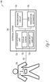
- FIG. 1 illustrates, by way of example and not limitation, an example of a neuromodulation system 100 and portions of an environment in which the neuromodulation system 100 may operate.
- the neuromodulation system 100 may include an ambulatory medical device (AMD), such as a subcutaneously implanted or a wearable electrostimulation device, associated with a subject 120 such as a patient.
- the AMD may include an implantable neuromodulator device (IND) 110.
- the IND 110 may generate one or more types of modifying agents for delivery to target tissues in the nervous system for medical diagnosis, or to achieve a desired therapeutic effects such as to modify, restore, or improve neural function.
- the modifying agents may include electrical, magnetic, or other forms of energy.
- the IND 110 may include a hermetically sealed can, which houses circuitry for generating the electrostimulation pulses, control circuitry, communication circuitry, and a battery, among other components.
- the electrostimulation pulses may be characterized by specified intensity, frequency, waveform, among other parameters, and may be used for stimulating a region of a spinal cord tissue (which may include, by way of example and not limitation, dorsal column, dorsal horn, spinal nerve roots such as the dorsal nerve root, and dorsal root ganglia), a region of a brain, or a peripheral nerve tissue.
- the IND 110 may be configured to be operably coupled to one or more leads that may be surgically placed in a specified position for the IND 110 to generate and deliver neuromodulation energy to a targeted region (e.g., volume of activation) of neural tissue, such as a brain, a spinal cord, or a peripheral neutral target tissue.
- a targeted region e.g., volume of activation
- neural tissue such as a brain, a spinal cord, or a peripheral neutral target tissue.
- FIG. 1 generally illustrates, by way of example and not limitation, a neuromodulation lead 124.
- the lead 124 may include respective one or more electrodes electrically coupled to the IND 110.
- the lead 124 may be a directional lead that includes at least some segmented electrodes circumferentially disposed about the directional lead. Two or more segmented electrodes may be distributed along a circumference of the lead.
- the actual number and shape of leads and electrodes may vary according to the intended application.
- Detailed description of construction and method of manufacturing percutaneous stimulation leads are disclosed in U.S. patent No. 8,019,439 , entitled “Lead Assembly and Method of Making Same," and U.S. Patent No. 7,650,184 , entitled “Cylindrical Multi-Contact Electrode Lead for Neural Stimulation and Method of Making Same".
- the neuromodulation system 100 may include an external system 130 that may communicate with the IND 110 such as via a communication link 103.
- the external system 130 may be an external programming system which may be configured to program the IND 110 and receive information about one or more signals acquired by IND 110 via a communication link 103.
- the external programming system may include a dedicated hardware/software system such as a programmer or a remote server-based patient management, or alternatively be defined predominantly by software running on a standard personal computer (PC).
- the external system 130 may include a user interface unit 131, a programmer circuit 134, and a lead orientation estimator 135.
- the user interface unit 131 may include a display screen 132 and may include a user input circuit 133.
- the external system 130 may display information on the display screen including parameters associated with programming of the IND 110, operational status of the IND 110, and the lead(s) (e.g. the lead 124) such as lead impedance or lead integrity indicators, battery status of the IND 110 such as battery longevity indicators, among others.
- the external system 130 may be coupled to a system, other than the IND 110, that may acquire, and/or store information about the operation of the IND 110 or the lead(s) (e.g., the lead 124).
- the external system 130 may be coupled to an imaging system, such as an X-ray machine, a computed tomography (CT) scanner, or a magnetic resonance imaging (MRI) system, to display an image of a portion of the lead under the X-ray, the CT scan, or the MRI scan.
- an imaging system such as an X-ray machine, a computed tomography (CT) scanner, or a magnetic resonance imaging (MRI) system
- CT computed tomography
- MRI magnetic resonance imaging
- the external system 130 may be coupled to a machine-readable medium such as a memory device, such as an electronic medical record (EMR) system, that stores image data of a portion of the lead.
- EMR electronic medical record
- the information displayed at the display screen 132 may be presented in a human-perceptible medium format, including a reconstructed digital image, a diagram, a table, a chart, or other textual, tabular, or graphical presentation of operational status of the IND 110 or the lead 124.
- the user input circuit 133 may include an input device that enables the system user to control the elements displayed on the display screen 132.
- the input device may include a keyboard, on-screen keyboard, mouse, trackball, touchpad, touch-screen, or other pointing or navigating devices.
- the input device may enable the system user to select and edit a portion of the image of the lead, such as to zoom, pan, or rotate the image of the lead, or switch from one view or viewing angle to another view or viewing angle of the image of the lead.
- the input device may also enable the system user to manually perform at least a part of the lead template generation process, or to confirm, override, or otherwise modify the automatically generated lead template, examples of which are discussed below, such as with reference to FIGS. 5-7 .
- the user input circuit 133 may be coupled to a programmer circuit 134 to enable a system user to program the IND 110 with desired parameters of neuromodulation therapy, or parameters for sensing a physiologic signal from the patient 150.
- the neuromodulation parameters may include stimulation amplitude, frequency, pulse width, duty cycle, duration, electrode polarity and configuration, sequence of stimulation, waveforms, a number of pulses in a train of pulses, a duration of the train of pulses, a pulse train-to-pulse train interval, a pattern of pulses, etc.
- the programmer circuit 134 may be a dedicated hardware/software system, or may be defined predominantly by software running on a standard PC. In an example as illustrated in FIG. 1 , the programmer circuit 134 may be coupled to the lead orientation estimator 135, and determine a neuromodulation parameter set including stimulation electrode and vector configuration using at least the estimated lead orientation such as produced by the lead orientation estimator 135.
- the lead orientation estimator 135 may determine an orientation of a lead, such as the lead 124, using image data of at least a portion of the lead.
- the image data of the lead may be obtained from an imaging system, or from a machine-readable medium such as a memory device configured to store the image data of the lead of interest.
- the lead orientation estimator 135 may determine the lead orientation using a template matching process, which includes image registration of a template image of a portion of the lead to a target image of the same portion of the lead.
- the template image of the lead may be predetermined and stored in the machine-readable medium.
- the lead orientation estimator 135 may include a template formulation circuit for generating the template of the lead or a portion of the lead. Examples of the lead orientation estimator 135, and the lead template formation circuit are described below, such as with reference to FIGS. 4-7 .
- the lead orientation estimator 135 may be implemented using instructions executable by a machine to provide human-perceptible information about the estimated lead orientation.
- the instructions may be stored in a machine-readable storage medium.
- at least a part of the machine-readable storage medium may be incorporated into the programmer circuit 134.
- the programmer circuit 134 may configure the display screen 132 to display the estimated lead orientation on the display screen 132, and to prompt a clinician to program the IND 110 with modulation parameters determined at least according to the estimated lead orientation.
- the communication link 103 between the external system and the IND may include a wireless link such as an inductive telemetry link or a radio-frequency telemetry link.
- the communication link 103 may include multiple communication links and intermediate devices between the external system and the IND, where the multiple communication links may include a wired link, a telecommunication link such as an internet connection, or a wireless link such as one or more of an inductive telemetry link, a radio-frequency telemetry link.
- the communication link 103 may provide for data transmission between the IND 110 and the external system 130.
- the transmitted data may include, for example, real-time physiological data acquired by the IND 110, physiological data acquired by and stored in the IND 110, therapy history data or data indicating IND operational status stored in the IND 110, stimulation parameters to the IND 110, one or more programming instructions to the IND 110 which may include configurations for sensing physiologic signal or delivering electrostimulation, device self-diagnostic test, among others.
- the IND 110 may be coupled to the external system 130 further via an intermediate control device, such as a handheld external remote control device to remotely instruct the IND 110 to generate electrical stimulation pulses in accordance with selected stimulation parameters produced by the external system 130.
- Portions of the IND 110 or the external system 130 may be implemented using hardware, software, firmware, or combinations thereof. Portions of the IND 110 or the external system 130 may be implemented using an application-specific circuit that may be constructed or configured to perform one or more particular functions, or may be implemented using a general-purpose circuit that may be programmed or otherwise configured to perform one or more particular functions. Such a general-purpose circuit may include a microprocessor or a portion thereof, a microcontroller or a portion thereof, or a programmable logic circuit, or a portion thereof.
- a “comparator” may include, among other things, an electronic circuit comparator that may be constructed to perform the specific function of a comparison between two signals or the comparator may be implemented as a portion of a general-purpose circuit that may be driven by a code instructing a portion of the general-purpose circuit to perform a comparison between the two signals.
- the neuromodulation system 100 could include a subcutaneous medical device, wearable medical devices, or other external medical devices.
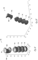
- FIG. 2 illustrates, by way of example and not limitation, a directional lead 200 with a marker.
- the illustrated directional lead 200 has an elongated cylindrical lead body 210 along a longitudinal lead axis, and includes insulative material coating that encloses wire conductors.
- the proximal end of the lead body 210 may include terminals that may be electrically coupled to the wire conductors and receive electrostimulation pulses from the IND 110.
- the directional lead 200 may include a plurality of electrodes disposed on the lead body 210 and electrically coupled to respective wire conductors, including a tip electrode 220 at the distal end of the lead and an axially disposed column electrode 240 (also known as a ring electrode) at the lead shaft.
- a tip electrode 220 at the distal end of the lead
- an axially disposed column electrode 240 also known as a ring electrode
- the directional lead 200 may include at least some segmented electrodes circumferentially disposed about the lead body 210, which may be used for directional stimulation of a target tissue.
- the directional lead 200 may include a first ring 231 of segmented electrodes 231a-231c distributed in a circumference of the lead body 210, and a second ring 232 of segmented electrodes 232a-232c distributed in another different circumference of the lead body 210.
- the segmented electrodes 231a-231c and 232a-232c may be disposed between the tip electrode 220 and the column electrode 240.
- one or both rings of the segmented electrodes 231a-231c and 232a-232c may be more proximally disposed than the column electrode 240.
- the number, shape, and circumferential distribution of the segmented electrodes, as well as the relative longitudinal positions of the segmented electrodes with respect to the column electrode 240, may vary according to the intended application.
- the directional lead 200 may include a marker 250 axially and circumferentially distributed on the lead body 210.
- the marker 250 may be configured to identify a rotational orientation about the longitudinal axis of the directional lead 200.
- the marker 250 is not electrically coupled to the IND 110, for either sensing a physiological signal or deliver modulation energy.
- the marker 250 may be more proximally disposed along the length of the lead than the plurality of electrodes 220, 231, 232, and 240 (as illustrated in FIG. 2 ), or at a different longitudinal position relative to the electrodes 220, 231, 232, and 240.
- the marker may include a first portion that has a radiopaque band 250A around a circumference of the lead body 210 and a second portion that has a radiolucent window 250B.
- the relative circumferential positions between the marker band 250A and the marker window 250B may be indicative of the rotational orientation of the directional lead 200.
- the rotational orientation of the directional lead 200 may be represented by a directional vector perpendicular to the longitudinal axis of the directional lead 200 pointing outwards towards the marker in an image of the lead or an image of the marker.
- the maker 250 can include a marker band 250A without the window such as the window 250B.
- the marker band 250A can be made of metal or other radiopaque compounds.
- FIGS. 3A-B illustrates, by way of example and not limitation, a CT scan image 300 of a portion of the directional lead 200 from different viewing angles.
- the CT scan image 300 may be produced by a CT scanner when the directional lead 200 is positioned at the target site such as in the brain, the spinal cord, or other neural targets.
- the imaging axis of the scanner may be oriented at a particular angle with respect to the longitudinal axis of the directional lead 200.
- the CT scan image 300 may be displayed on the display screen 132, and controllably adjusted and edited by a system user through the user input circuit 133, including image zooming, highlighting, or changing a viewing angle, among other operations.
- the CT scan image 300 may present images of the electrodes on the directional lead 200, including the tip electrode image 320 corresponding to the tip electrode 220, segmented electrodes image 331 corresponding to the ring 231 of the segmented electrodes 231a-c, segmented electrodes image 332 corresponding to the ring 232 of the segmented electrodes 232a-c, and the column electrode image 340 corresponding to the column electrode 240.
- the marker image 350 of the marker 250 may have a distinctive anisotropic shape. Under the CT scan, as illustrated in FIGS.
- the radiopaque band 250A has a convex shape of a bulge 350A protruding outwards radially away from the lead axis
- the radiolucent window 250B has a concave shape of a dimple 350B curving inward radially towards the lead axis.
- the different shapes of 350A and 350B correspond to the relative circumferential positions of the marker band 250A and the marker window 250B in the directional lead 200.
- the CT scan image 300, or a portion of the image 300 such as the bulge 350A (corresponding to marker band 250A) or the dimple 350B (corresponding to the marker window 250B) may be used to identify a rotational orientation of the directional lead 200 about the longitudinal axis.
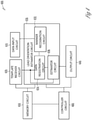
- FIG. 4 illustrates, by way of example and not limitation, a lead orientation estimator 400, which may be an embodiment of the lead orientation estimator 135.
- the lead orientation estimator circuit 400 may include one or more of a data input circuit 410, a template receiver 420, a lead orientation estimator circuit 430, an output unit 440, a memory unit 450, and a controller circuit 460.
- the data input circuit 410 may receive image data of at least a portion of a neuromodulation lead, such as the directional lead 200, that has a marker structure such as the marker 250 as shown in FIG. 2 .
- the neuromodulation lead may have an unknown lead orientation.
- the data input circuit 410 may be coupled to an imaging system, or a machine-readable medium such as a memory circuit 450, to receive image data.
- the image data may include data of a computed tomography (CT) scan of the lead such as the CT scan image 300 of the lead 200, or the CT scan image 350 of the marker 250, as illustrated in FIGS. 3A-B .
- CT computed tomography
- the image data may also include an X-ray image, an ultrasound image, a MRI image, a positron emission tomography (PET) image, or a single-photon emission computed tomography (SPECT) image, among others.
- CT computed tomography
- PET positron emission tomography
- SPECT single
- the template receiver circuit 420 may receive at least one template of a reference lead, such as a reference directional lead.
- the reference lead may be identical to, or of the same type of, the lead used for producing the image data received at the data input circuit 410.
- the template may be constructed using image data of the lead when the lead is substantially aligned with an imaging axis, and positioned with a specified and known rotational orientation.
- the image data used to construct the template may be obtained from the same type of imaging system used to produce the image data of the lead as received by the data input circuit 410.
- the template may be constructed using the CT scan of the lead or the same particular portion of the lead when the lead is positioned with a specified and known rotational orientation.
- the template receiver circuit 420 may receive at least one template that has been created and stored in a machine-readable medium such as the memory circuit 450.
- the template receiver circuit 420 may be coupled to a template formation circuit configured to create at least one template using image data of a portion of the direction lead, such as the marker image 350 as shown in FIGS. 3A-B .
- the template formation circuit may be separated from the lead orientation estimator circuit 400, or included as a part of the lead orientation estimator circuit 400.
- the template may include a reference data cube (X R ) of the marker and a reference marker direction vector ( v R ) indicative of the specified rotational orientation of the lead about the longitudinal axis of the lead.
- the reference data cube (X R ) may be a selected portion of the image data extracted from the marker image 350 of a reference lead.
- the reference data cube (X R ) may be a three-dimensional (3D) data array of a volume of the marker image, such as the marker band image 350A.
- the template may include other forms of data representation, in lieu of the data cube (X R ), that represent anisotropy of the maker image 350, such as an isosurface of the marker band image 350A.
- the reference marker direction vector ( v R ) may be generated using the image data of the marker image 350 or the image data of the marker band image 350A. Examples of the template construction using the image data of the lead or a portion of the lead are discussed below, such as with reference to FIGS. 5 and 6 .
- the lead orientation estimator circuit 430 may be coupled to the data input circuit 410 and the template receiver circuit 420, and configured to estimate the lead orientation using the image data of a target lead such as received from the data input circuit 410 and the template provided by the template receiver circuit 420.
- the lead orientation estimator circuit 430 may include one or more of a marker recognition circuit 432, a data registration circuit 434, and an estimator circuit 436.
- the marker recognition circuit 432 may identify the marker from the image data of the lead.
- the marker recognition circuit 432 may include an image segmentation module that may partition the image data of the lead into a plurality of segments that represent various structural elements on the lead, such as image segments corresponding to one of the electrodes 220, 231, 232, or 240, or the marker 250.
- the data input circuit 410 may receive pre-segmented image data of the marker, instead of the image data of the entire lead. Segmentation module may therefore be excluded from the data registration circuit 434. As illustrated in FIGS.
- the marker 250 may have characteristic anisotropic shape 350 under the CT scan, which includes a bulge 350A protruding outwards, and a dimple 350B of curving inward, relative to the lead axis.
- the marker recognition circuit 432 may identify the marker by recognizing such anisotropic shape of the marker under the CT scan using the data of the image segments.
- the marker recognition circuit 432 may further use the image data of the identified marker to produce a target data cube (X T ) of the marker. Similar to the reference data cube X R extracted from the marker image of the reference lead with a specified and known lead orientation, the target data cube X T may be extracted from a selected portion such as the marker image 350 of the target lead with a target, unknown lead orientation. In an example, X T may have a similar data structure as X R , such as a 3D data array of a volume of the marker image such as the marker band image 350A corresponding to the target lead. Examples of the marker identification and construction of the target data cube X T are discussed below, such as with reference to FIG. 6 .
- the data registration circuit 434 may register the reference data cube X R to the target data cube X T . Because both X R and X T have the same image data format and constructed into a similar data structure, the data registration circuit 434 may produce a transformation operator ⁇ for transforming X R into a transformed reference data cube ⁇ (X R ), or a "registered reference data cube.”
- the transformation operator ⁇ may be an affine transformation.
- the affine transformation may include rigid transformations that preserve the distance, such as one or any combination of a translation, a rotation, or a reflection operation; or non-rigid transformations such as one or any combination of stretching, shrinking, or model-based transformations such as radial basis functions, splines, or finite element model.
- the transformation may include both the rigid transformation to bring reference data cube X R in global alignment with the size and orientation of the target data cube X T , and the non-rigid transformation to reduce the local geometric discrepancies by aligning the reference data cube X R with the target data cube X T .
- the transformed reference data cube ⁇ (X R ) may be in a coordinate system similar to that of the target data cube X T .
- the data registration circuit 434 may determine the transformation operator ⁇ as one that causes the transformed reference data cube ⁇ (X R ) to match the target data cube X T within a specified margin.
- the transformation operator ⁇ may minimize the multidimensional distance between ⁇ (X R ) and X T , such as when the distance falls below a specified threshold.
- Examples of the distance measure may include L1 norm, L2 norm (i.e., Euclidian distance), infinite norm, other norm in the normed vector space, or a dissimilarity measure between ⁇ (X R ) and X T such as correlation coefficient, mutual information, or ratio image uniformity.
- the estimator circuit 436 may estimate the orientation, including a rotational orientation, of the lead using the reference marker direction vector v R of the template received by the template receiver circuit 420, and the transformation operator ⁇ as produced by the marker recognition circuit 432.
- the estimated marker direction vector ⁇ T may be indicative of the rotational orientation of the lead relative to an imaging axis used for producing the image data of the at least a portion of the lead.
- the output circuit 440 may produce a graphical representation of the lead and at least the estimated target marker direction vector ⁇ T .
- the output circuit 400 may additionally produce graphical representations of the target marker, the reference marker of the template, the reference marker band direction vector, among others.
- the output circuit 440 may be coupled to the display screen 132 as shown in FIG. 1 to display the graphical representations of the lead, the estimated target marker direction vector ⁇ T , or other information.
- the controller circuit 460 may control the target lead image data operations at the data input circuit 410, the creation, storage, and retrieval of templates at the template receiver circuit 420, the lead orientation estimation at the least orientation estimator circuit 430, presentation generation at the output circuit 440, and the data flow and instructions among these components and respective subcomponents.
- the controller circuit 460 may control the communication between the lead orientation estimator 400 and the programmer circuit 134, the user interface unit 131, or an electrostimulator circuit in the IND 110 for generate directional electrostimulation for modulating the body tissue using the lead oriented at least according to the determined rotational.
- FIG. 5 illustrates, by way of example and not limitation, a template formation circuit 500 and portions of the environment in which it operates.
- the template formation circuit 500 may be a standalone circuit separated from the lead orientation estimator circuit 400, or it may be integrated as a part of lead orientation estimator circuit 400.
- the template formation circuit 500 may include a reference marker recognition circuit 510, a reference data cube (X R ) extractor 520, and a reference direction vector generator 530.
- the reference lead has a marker such as the marker 250 has shown in FIG. 2 .
- the image data may be from the same type of imaging system used to produce the image data of the lead as received by the data input circuit 410, such as image data of the CT scan of the lead when the lead is positioned with a specified and known rotational orientation.
- the template formation circuit 500 may be coupled to the data input circuit 410 to receive image data of a reference lead obtained when the lead is substantially aligned with an imaging axis.
- the reference marker recognition circuit 510 may have a similar structure as the marker recognition circuit 432, and include a reference marker identifier circuit 512 and a reference lead axis detector circuit 514.
- the reference marker recognition circuit 510 may optionally include an image segmentation circuit to partition the image data of the reference lead into a plurality of segments representing various structural elements including the electrodes (such as one or more of the electrodes 220, 231, 232, and 240 shown in FIG. 2 ) and the marker (such as marker 250 shown in FIG. 2 ).
- the image segmentation circuit may be excluded from the reference data registration circuit 434 if the input circuit 410 receives data of segmented image of the marker, instead of the image data of the entire lead.
- the reference marker identifier circuit 512 may identify the marker by recognizing the anisotropic shape of the marker, such as marker band image 350A and maker window image 350 of a CT scan, as illustrated in FIGS. 3A-B .
- the reference lead axis detector circuit 514 may automatically identify a lead tip and a lead shaft from the image segments of the lead, and detect a reference lead axis 620 such as by joining the identified lead tip and lead shaft.
- the reference marker recognition circuit 510 may be coupled to the user interface unit 131, and an image of the lead used for forming a template may be displayed on the display screen 132.
- a system user may identify the lead tip and the lead shaft from the displayed image of the lead, and provide input to the reference lead axis detector circuit 514 about the positions such as coordinates of the lead tip and the lead shaft, and the reference marker recognition circuit 510 may detect the reference lead axis 620 by joining the user-provided lead tip and lead shaft.
- the reference data cube extractor 520 may produce the reference data cube X R of the template using the image data of the marker as identified by the reference marker identifier circuit 512 and the detected lead axis as provided by the reference lead axis detector circuit 514.
- FIG. 6A illustrates a schematic of a data cube formed out of the marker 650 along the lead shaft 610.
- the reference data cube 660 may include image data within a volume of a specified shape, dimension, and orientation with respect to the identified lead axis 620, such as a cylindrical volume containing the marker 650 and axially aligned with the detected lead axis 620.
- the reference data cube 660 may be sized and shaped to cover a portion of the lead image such as the bulge corresponding to the marker band, or to cover the entire lead.
- the reference data cube 660 may in some examples include a 2D data array representing a 2D image of at least a portion of the reference lead.
- the reference data cube extractor 520 may include a resampling module that resamples the image data of the reference data cube 660.
- the image data of the reference data cube may be up-sampled to have a higher spatial resolution (as illustrated by finer or smaller grid within the reference data cube 660 in FIG. 6A ) than the original spatial resolution of the image of the lead (as illustrated by coarser or larger grid outside the reference data cube 660 in FIG. 6A ).
- Examples of the up-sampling to improve the spatial resolution may include pixel interpolation, spatial filtering, among other methods.
- the reference data cube 660 may have an isotropic spatial resolution of approximately 0.1 mm. The lead axis detection and the data cube formation as discussed above may also be used by the marker recognition circuit 432 to produce the target data cube X T .
- the reference direction vector generator 530 may use the reference data cube X R to determine the reference direction vector v R , which may be indicative of the rotational orientation of the lead with respect to the lead axis.
- FIG. 6B which illustrates a portion of the CT scan image of the lead, including images of the lead shaft 610, the bulge 650A corresponding to the marker band 250A, and the dimple 650B corresponding to the maker window 250B.
- the reference direction vector 685, determined using the reference data cube X R 660, is shown as an arrow pointing outwards radially from the bulge of the marker.
- the reference direction vector generator 530 may determine the reference direction vector v R using the extracted reference data cube X R .
- FIGS. 6C-D illustrate two methods used by the reference direction vector generator 530 to determine the v R .
- a midpoint 630 of the reference marker 650 may be detected using the identified lead tip and the lead shaft, and the known dimensional information such as the longitudinal position of the marker relative to the lead tip.
- a bulging point 670 within the identified marker 650 may be automatically, or based on a user input, determined as a point on the bulge 650A of the marker that is spatially farther away from the midpoint 630 of the marker than some other points within the identified marker 650.
- An initial marker direction vector 675 which originates at the midpoint 630 of the marker and points to the bulging point 670, may then be generated.
- a projection plane 692 may be determined that is perpendicular to the detected lead axis 620 and across the midpoint 630.
- the reference direction vector generator 530 may project the initial marker direction vector 675 onto the projection plane 692, resulting in a projected vector 685 that points to a bulging point 680 within the maker 650. Such a projected vector 685 may be determined as the reference direction vector VR.
- Another method that the reference direction vector generator 530 may use to determine the reference direction vector v R may be visualized using the illustration in FIG. 6D
- a symmetric plane 694 through the detected lead axis 620 may be identified, such that the image data of the marker is substantially reflective symmetric about the symmetric plane 694.
- Two candidate marker direction vectors, 681 and 682 may be produced along the symmetric plane 694. Both candidate marker direction vectors 681 and 682 originate from and perpendicular to the lead axis 620, but point to two opposite directions.
- the reference direction vector generator 530 may make a comparison of the two candidate marker direction vectors 681 and 682 to identify one candidate direction vector (e.g., candidate vector 681 in FIG.
- the reference direction vector generator 530 may then determine the candidate vector spatially closer to the bulge 650A (e.g., candidate vector 681), as the reference direction vector v R .
- the reference direction vector generator 530 may perform eigenvalue decomposition of an initial marker direction vector generated automatically or based on a user input, such as the initial marker direction vector 675, and determine the reference direction vector v R using an eigenvector produced by the eigenvalue decompensation.
- the reference direction vector generator 530 may additionally or alternatively produce a morphologic characterization of a portion of the marker, such as a curvature of the bulge 650A, and determine the reference direction vector v R using at least the curvature of the bulge 650A.
- the reference data cube X R as produced by the reference data cube extractor 520 and the reference direction vector v R as produced by the reference direction vector generator 530, may be stored in the memory circuit 450.
- the X R and v R may also be received by the template receiver circuit 420, and used by the lead orientation estimator 400 to estimate the orientation of the lead.
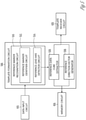
- FIG. 7 illustrates, by way of example and not limitation, a lead orientation estimator circuit 730 based on multi-atlas registration.
- the lead orientation estimator circuit 730 may be an embodiment of the lead orientation estimator circuit 430.
- the lead orientation estimator circuit 730 may be coupled to the data input circuit 410 to receive image data of at least a portion of a lead, such as the directional lead 200, with a target, unknown lead orientation.
- the lead orientation estimator circuit 730 may include a marker recognition circuit 732, which may be an embodiment of the marker recognition circuit 432, which is configured to produce a target data cube X T .
- the lead orientation estimator circuit 730 may include an image registration circuit 734 coupled to a template receiver circuit 720 to receive two or more templates (e.g., Template 1, Template 2, ..., Template K) of the lead.
- Each template includes a respective reference data cube X R and the corresponding reference direction vector v R .
- at least one template may be formed by the template formation circuit 500 as previously discussed with reference to FIGS. 5 and 6 .
- one or more of the templates may include other forms of data representation, in lieu of the data cube (X R ), that represent anisotropy of the maker image, such as an isosurface of the marker band image.
- the image registration circuit 734 may perform a multi-atlas registration, including registering at least some of the reference data cubes ⁇ X R1 , X R2 , ..., X RK ⁇ associated with the respective two or more templates ⁇ Template 1, Template 2, ..., Template K ⁇ to the target data cube X T , such as by using image segmentation and image transformation as previously discussed with reference to the data registration circuit 434 in FIG. 4 .
- the image registration circuit 734 may perform image registration, and produce two or more transformation operators ⁇ 1 , ⁇ 2 , ..., ⁇ K ⁇ corresponding to the respective templates ⁇ Template 1, Template 2, ..., Template K ⁇ .
- Each transformation operator ⁇ i transforms the corresponding reference data cube X Ri into a transformed reference data cube ⁇ i (X Ri ) that matches X T within a specified margin, such as a multi-dimensional distance or a dissimilarity measure between ⁇ i (X Ri ) and X T falling below a specified threshold.
- the fusion function may be a linear or a nonlinear operator, including an averaging, a weighted average, a decision tree, a voting model, a regression model, a neural network model, a fuzzy logic model, a neural network model, or a support vector machine model, among others.
- the combined estimate of the marker direction vector ⁇ T may more be a more accurate and reliable indicator of the rotational orientation of the lead.
- the fusion circuit 738 may additionally produce a confidence indicator such as a confidence bound of the estimated rotational orientation of the lead using the two or more estimated marker direction vectors.
- the combined estimate of the marker direction vector ⁇ T , and the confidence bound of ⁇ T may be passed to the output circuit 440 to produce graphical representations of ⁇ T and optionally along with other information including the target marker, the reference marker of the template, the reference marker band direction vector, etc.
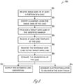
- FIG. 8 illustrates, by way of example and not limitation, a method 800 that includes estimating an orientation of a lead.
- the method 800 may be implemented and operate in a medical system, such as a programming system or a remote server-based patient management system in communication with an ambulatory medical device (AMD) configured to provide electrical therapy to the patient.
- the method 800 may be implemented in and executed by the external system 130 to determine the orientation of the implantable lead 124 for SCS, and to provide a recommendation of modulation therapy using the orientation of the lead.
- the method may be used intraoperatively to determine location and orientation of lead placement to achieve desired electrode-tissue contacts, or during patient follow-ups to adjust of modulation therapy based at least on the information about lead orientation.
- the method 800 begins at step 810, where image data of at least a portion of a lead is received, such as from an imaging system such as an X-ray machine, a CT scanner, a MRI scanner, a positron emission tomography (PET) scanner a single-photon emission computed tomography (SPECT) scanner among others.
- the image data may be received from a machine-readable medium such as a memory circuit 450.
- the lead may have a marker structure including a radiopaque marker band, such as the directional lead shown in FIG. 2 .
- the lead is positioned in target tissue structures with a target, unknown lead orientation.
- the image data may include CT scan image of at least a portion of the lead including image data of the marker structure, such as illustrated in FIGS. 3A-3B .
- the marker may be identified using the image data of the lead, such as by using the marker recognition circuit 432 as shown in FIG. 4 .
- the input image of the lead may be segmented, and a characteristic anisotropic shape of the marker portion on the lead may be identified.
- the marker under the CT scan has a bulge 350A protruding outwards, and a dimple 350B of curving inward, relative to the lead axis.
- a target data cube X T corresponding to the identified marker on the lead, may be produced.
- Lead tip and lead shaft of the lead may be automatically, or at least based on a user's input, identified using the image segments of the lead.
- a lead axis may be detected such as by joining the identified lead tip and lead shaft.
- the target data cube X T may then be produced using image data of the marker and the detected lead axis.
- the target data cube X T may be sized, shaped, and oriented to contain the marker image and be axially aligned with the detected lead axis.
- the target data cube X T may be sized, shaped, and oriented to cover only the bulge of the marker corresponding to the marker band, or the entire lead.
- the target data cube X T may be a 2D data array.
- the image data within the target data cube may be resampled to have a higher spatial resolution than that of the image of the lead.
- At 840, at least one template of the lead may be received, such as from a machine-readable medium such as the memory circuit 450, or a template formation circuit.
- the reference lead may be identical to, or of the same type of, the lead used for producing the image data received at the data input circuit 410.
- the template may be constructed using image data of the lead when the lead is substantially aligned with an imaging axis and positioned with a specified and known rotational orientation.
- the template may include a reference data cube (X R ) of the marker and a reference marker direction vector ( v R ) indicative of the specified rotational orientation of the lead about the longitudinal axis of the lead.
- the reference data cube X R may be a selected portion of the image data extracted from the marker image, and has similar data structure as the target data cube X T , such as a 3D data array.
- other forms of data representation that represent anisotropy of the maker image can be used. For example, an isosurface of the identified marker band can be produced at 830, and an isosurface of the marker of the template can be received at 840.
- the reference data cube X R may be registered to the target data cube X T , to produce a transformation operator ( ⁇ ) for transforming X R into a transformed reference data cube ⁇ (X R ), or a "registered reference data cube.”
- the transformation may include an affine transformation such as a rigid transformation (such as one or any combination of translation, a rotation, or a reflection operation), non-rigid transformation (such as one or any combination of stretching, shrinking, or model-based transformations), or a combination of rigid and non-rigid transformations.
- the transformation operator ⁇ may be determined when the registered reference data cube ⁇ (X R ) matches the target data cube X T within a specified margin, such as when multi-dimensional distance or a dissimilarity measure between ⁇ (X R ) and X T falling below a specified threshold.
- the orientation of the direction lead may be estimated using the reference marker direction vector v R and the transformation operator ⁇ .
- a graphical representation of the estimated orientation of the lead may be produced, and displayed such as on the display screen 132 of the user interface unit. Other information, including the target marker, the reference marker of the template, or the reference marker band direction vector, may also be displayed. Additionally or alternatively, at 874, the determined orientation of the lead may be used to produce a recommendation of lead positioning, and providing directional electrostimulation to the body tissue using the two or more directional electrodes on the lead oriented at least according to the determined rotational orientation.
- the method 800 may be modified to perform orientation estimation based on multi-atlas image registration.
- two or more templates of the lead ⁇ Template 1, Template 2, ..., Template K ⁇
- each template including a respective reference data cube X R and the corresponding reference direction vector v R .
- the reference data cubes ⁇ X R1 , X R2 , ..., X RK ⁇ associated with the respective two or more templates may be registered to the target data cube X T , and the corresponding transformation operators ⁇ 1 , ⁇ 2 , ..., ⁇ K ⁇ can be produced.
- a confidence bound of the estimated rotational orientation of the lead may also be estimated using the two or more estimated marker direction vectors.
- FIG. 9 illustrates, by way of example and not limitation, a method 900 for automatic lead template generation for a lead.
- the method 900 may be implemented in and executed by the template formation circuit 500.
- the method 900 begins at 910, where image data of the lead may be received.
- the image data of the lead may be obtained by using an imaging system when the lead is substantially aligned with an imaging axis.
- the image data may be from the same type of imaging system used to produce the image data of the lead, such as image data of the CT scan of the lead when the lead is positioned with a specified and known rotational orientation.
- a lead axis may be detected using the image data of the lead.
- the image of the lead may be segmented, and a lead tip and a lead shaft may be automatically identified from the image segments of the lead.
- the image of the lead may be displayed on the display screen, and a system user may identify the lead tip and the lead shaft from the image of the lead and provide input about the positions such as coordinates of the lead tip and the lead shaft.
- a reference lead axis may be formed such as by joining the identified lead tip and lead shaft.
- the reference marker structure may be identified from the image data, at least based on anisotropic shape of the marker (such as the characteristic anisotropic shape 350 under the CT scan as shown in FIG. 3 ) using the data of the image segments.
- a reference data cube X R of the reference marker may be produced using the image data of the marker and the detected lead.
- the reference data cube X R may have a specified dimension and orientation with respect to the identified lead axis.
- the dimension of the reference data cube X R may contain the marker and is aligned with the detected lead axis, or only covers a portion such as the bulge of the marker corresponding to the marker band, or the entire lead.
- the step 940 may also include resampling the image data within the target data cube to have a higher spatial resolution than that of the image of the lead.
- a reference direction vector ( v R ) may be determined using the reference data cube X R .
- the reference direction vector ( v R ) may be indicative of the rotational orientation of the lead with respect to the lead axis.
- the method 950 includes detecting a midpoint of the marker using the identified lead tip and the lead shaft. A bulging point within the identified marker may be detected as a point spatially farther away from the midpoint of the marker than other points within the identified marker. An initial marker direction vector may be generated, which originates at the midpoint of the marker and points to the bulging point.
- a reference direction vector ( v R ) may then be determined as a projection of the initial marker direction vector onto a plane perpendicular to the detected lead axis.
- a symmetric plane through the detected lead axis may be identified.
- the image data of the marker may be substantially reflective symmetric about the symmetric plane.
- Two candidate marker direction vectors may be formed along the symmetric plane. Each of two candidate marker direction vectors is perpendicular to the lead axis, originates from and points to two opposite directions.
- the reference direction vector ( v R ) may be determined as one of the two candidate marker direction vectors that is spatially closer to a bulging point within the identified marker than the other of the two candidate marker direction vector.
- the method 950 includes eigenvalue decomposition of an initial marker direction vector generated automatically or based on a user input, and determining the reference direction vector v R using an eigenvector produced by the eigenvalue decompensation. Morphologic characterization of a portion of the marker, such as a curvature of the bulge 650A, may be used to determine the reference direction vector v R using at least the curvature of the bulge 650A.
- the method 800 may be implemented as instructions stored in a machine-readable storage medium.
- the machine may be in a form of a computer system, which may include a processor, memory, video display unit, an alpha-numeric input device, a user interface with a navigation device, a disk drive unit, a signal generation device, a network interface device, among others.
- the instructions may cause machine to perform any part of the methods 800 or 900 or any variants thereof.
- the machine may operate as a standalone device or may be connected (e.g., networked) to other machines. While only a single machine is illustrated, the term "machine" shall also be taken to include any collection of machines that individually or jointly execute a set (or multiple sets) of instructions to perform any one or more of the methodologies discussed herein.
- the machine-readable medium may include a single medium or multiple media (e.g., a centralized or distributed database, and/or associated caches and servers) that store the one or more instructions or data structures.
- the term “machine-readable storage medium” shall also be taken to include any tangible medium that is capable of storing, encoding or carrying instructions for execution by the machine and that cause the machine to perform any one or more of the methods of the present invention, or that is capable of storing, encoding or carrying data structures used by or associated with such instructions.
- the term “machine-readable storage medium” shall accordingly be taken to include, but not be limited to, solid-state memories, and optical and magnetic media.
- machine-readable media include non-volatile memory, including by way of example, semiconductor memory devices (e.g., erasable programmable read-only memory (EPROM), electrically erasable programmable read-only memory (EEPROM)) and flash memory devices; magnetic disks such as internal hard disks and removable disks; magneto-optical disks; and CD-ROM and DVD-ROM disks.
- semiconductor memory devices e.g., erasable programmable read-only memory (EPROM), electrically erasable programmable read-only memory (EEPROM)
- flash memory devices e.g., erasable programmable read-only memory (EPROM), electrically erasable programmable read-only memory (EEPROM)
- flash memory devices e.g., erasable programmable read-only memory (EPROM), electrically erasable programmable read-only memory (EEPROM)
- flash memory devices e.g., erasable programmable read-only memory (EPROM),
- machine-readable medium and machine-readable storage medium are applicable even if the machine-readable medium is further characterized as being “non-transitory.”
- any addition of "non-transitory,” such as non-transitory machine-readable storage medium is intended to continue to encompass register memory, processor cache and RAM, among other memory devices.
- the instructions may further be transmitted or received over a communications network using a transmission medium.
- the instructions may be transmitted using the network interface device and any one of a number of well-known transfer protocols (e.g., HTTP).
- Examples of communication networks include a LAN, a WAN, the Internet, mobile telephone networks, plain old telephone (POTS) networks, and wireless data networks (e.g., WiFi and WiMax networks).
- POTS plain old telephone
- the term "transmission medium” shall be taken to include any intangible medium that is capable of storing, encoding or carrying instructions for execution by the machine, and includes digital or analog communications signals or other intangible media to facilitate communication of such software.
- Method examples described herein may be machine or computer-implemented at least in part. Some examples may include a computer-readable medium or machine-readable medium encoded with instructions operable to configure an electronic device to perform methods as described in the above examples.
- An implementation of such methods may include code, such as microcode, assembly language code, a higher-level language code, or the like. Such code may include computer readable instructions for performing various methods. The code may form portions of computer program products. Further, in an example, the code may be tangibly stored on one or more volatile, non-transitory, or non-volatile tangible computer-readable media, such as during execution or at other times.
- Examples of these tangible computer-readable media may include, but are not limited to, hard disks, removable magnetic disks, removable optical disks (e.g., compact disks and digital video disks), magnetic cassettes, memory cards or sticks, random access memories (RAMs), read only memories (ROMs), and the like.
Description
- This document relates generally to medical devices for detecting an orientation of a lead.
- Neuromodulation, also referred to as neurostimulation, has been proposed as a therapy for a number of conditions. Examples of neuromodulation include Spinal Cord Stimulation (SCS), Deep Brain Stimulation (DBS), Peripheral Nerve Stimulation (PNS), and Functional Electrical Stimulation (FES). Implantable neuromodulation systems have been applied to deliver such a therapy. An implantable neuromodulation system may include an implantable neuromodulator, also referred to as an implantable pulse generator, and one or more implantable leads each including one or more electrodes. The implantable neuromodulator may deliver neuromodulation energy through one or more electrodes placed on or near a target neural tissue. An external programming device may be used to program the implantable neuromodulator with parameters controlling the delivery of the neuromodulation energy.
-
PCT Patent Application Publication No. WO2009/139917 discloses a system and method for displaying a volume of activation (VOA) which may include a processor that displays via a display device a model of a portion of a patient anatomy that includes anatomical structures, displays via the display device and overlying the display of the model a VOA associated by the processor with a set of anatomical stimulation parameter settings, the display of the VOA, and graphically identifies interactions between the displayed VOA and a first subset of the anatomical structures associated with one or more stimulation benefits and a second subset of the anatomical structures associated with one or more stimulation side effects, where the graphical identifications differ depending on whether the interaction is with the first subset or the second subset. -
PCT Patent Application Publication No. WO2014/151651 discloses system and methods to facilitate intra-operative procedures and planning. A method can include storing tracking data in memory, the tracking data being generated by a tracking system to represent a location of an object in a tracking coordinate system of the tracking system. The method can also include storing a patient-specific implicit model in memory, the patient-specific implicit model being generated based on image data acquired for the patient to define geometry of an anatomical structure of the patient. The method can also include registering the tracking data and the patient-specific implicit model in a common three-dimensional coordinate system. The method can also include generating an output visualization representing a location of the object relative to the geometry of the anatomical structure of the patient in the common coordinate system. - Efficacy and efficiency of certain neuromodulation therapies may be affected by the position and/or orientation of the implantable leads. Proper lead direction and orientation may allow the lead to be used to more accurately target tissue that is desired to be modulated while avoiding or reducing undesirable side-effects caused by unintentionally modulating neighboring cell populations next to or around the target neural structures. Additionally, an improved lead position and/or orientation may also reduce energy consumption and thereby extending longevity of the implantable neuromodulator.
- Some neuromodulation systems, such as those used for DBS or SCS, may include leads that have a large number of electrodes for stimulating neural targets. In the context of DBS, a neuromodulation lead may have a complex arrangement of multiple electrodes that are not only distributed axially along the leads, but also distributed circumferentially around the lead. Such a lead, also known as a directional lead, presents a multitude of selections of stimulation parameter sets to the clinician.
- Selection of the electrodes on a lead to be active and programming neuromodulation using the selected electrodes may be complicated and time consuming. Diagnostic imaging equipment may be used to localize circumferential locations of the electrodes in the operating room or during follow-up, an orientation of the lead may be determined with respect to an imaging axis of the diagnostic equipment. Conventional lead location methods may be used to identify longitudinal contacts of column electrodes (also known as ring electrodes) along the length of the lead relative to a neural target. However, such conventional lead location methods may not provide adequate information about the rotational orientation of the lead. The present subject matter effectively and efficiently determines an orientation of a lead to facilitate electrode selection and programming of the neuromodulation system.
- This document discusses, among other things, an embodiment of a system for determining a rotational orientation of a lead for use in electrostimulation of a body tissue. The system may receive image data of at least a portion of the lead including image data of a marker configured to identify a rotational orientation of the lead. The system may receive at least one template of the lead having a specified rotational orientation. Each template may include a reference data cube and a reference marker direction vector. The system may generate a target data cube of the marker using the image data of the marker, and register the reference data cube to the target data cube to produce a transformation operator. The system may estimate the rotational orientation of the lead using the reference marker direction vector and the determined transformation operator.
- This Overview is an overview of some of the teachings of the present application and not intended to be an exclusive or exhaustive treatment of the present subject matter. Further details about the present subject matter are found in the detailed description and appended claims. Other aspects of the invention will be apparent to persons skilled in the art upon reading and understanding the following detailed description and viewing the drawings that form a part thereof, each of which are not to be taken in a limiting sense. The scope of the present invention is defined by the appended claims only.
- Various embodiments are illustrated by way of example in the figures of the accompanying drawings. Such embodiments are demonstrative and not intended to be exhaustive or exclusive embodiments of the present subject matter.
-
FIG. 1 illustrates, by way of example and not limitation, a neuromodulation system and portions of an environment in which the neuromodulation system operates. -
FIG. 2 illustrates, by way of example and not limitation, a directional lead with a marker. -
FIGS. 3A-B illustrate, by way of example and not limitation, images from a computerized tomography (CT) scan of a portion of a directional lead from different viewing angles. -
FIG. 4 illustrates, by way of example and not limitation, a lead orientation estimator circuit. -
FIG. 5 illustrates, by way of example and not limitation, a template formation circuit and portions of an environment in which it operates. -
FIGS. 6A-D illustrate, by way of example and not limitation, methods for forming a data cube and directional vector of a template of marker. -
FIG. 7 illustrates, by way of example and not limitation, a lead orientation estimator circuit based on multi-atlas registration. -
FIG. 8 illustrates, by way of example and not limitation, a method that includes estimating an orientation of a lead. -
FIG. 9 illustrates, by way of example and not limitation, a method for automatic lead template generation for a lead. - The invention is defined by
claim 1. Preferred embodiments are disclosed by the dependent claims. Various examples disclosed herein include also further systems, devices, and methods for determining a rotational orientation of a lead for use in electrostimulation of a body tissue. Image data of at least a portion of the lead, including image data of a marker configured to identify a rotational orientation of the lead, may be used to estimate the lead orientation. A system may receive at least one template of the lead having a specified rotational orientation. Each template may include a reference data cube and a reference marker direction vector. The system may generate a target data cube of the marker using the image data of the marker, and register the reference data cube to the target data cube to produce a spatial transformation operator. The rotational orientation of the lead may be estimated such as by applying the spatial transformation operator to the reference marker direction vector. -
FIG. 1 illustrates, by way of example and not limitation, an example of aneuromodulation system 100 and portions of an environment in which theneuromodulation system 100 may operate. Theneuromodulation system 100 may include an ambulatory medical device (AMD), such as a subcutaneously implanted or a wearable electrostimulation device, associated with a subject 120 such as a patient. By way of example and not limitation, the AMD may include an implantable neuromodulator device (IND) 110. TheIND 110 may generate one or more types of modifying agents for delivery to target tissues in the nervous system for medical diagnosis, or to achieve a desired therapeutic effects such as to modify, restore, or improve neural function. The modifying agents may include electrical, magnetic, or other forms of energy. - In an example, the
IND 110 may include a hermetically sealed can, which houses circuitry for generating the electrostimulation pulses, control circuitry, communication circuitry, and a battery, among other components. The electrostimulation pulses may be characterized by specified intensity, frequency, waveform, among other parameters, and may be used for stimulating a region of a spinal cord tissue (which may include, by way of example and not limitation, dorsal column, dorsal horn, spinal nerve roots such as the dorsal nerve root, and dorsal root ganglia), a region of a brain, or a peripheral nerve tissue. TheIND 110 may be configured to be operably coupled to one or more leads that may be surgically placed in a specified position for theIND 110 to generate and deliver neuromodulation energy to a targeted region (e.g., volume of activation) of neural tissue, such as a brain, a spinal cord, or a peripheral neutral target tissue. -
FIG. 1 generally illustrates, by way of example and not limitation, aneuromodulation lead 124. Thelead 124 may include respective one or more electrodes electrically coupled to theIND 110. In an example, thelead 124 may be a directional lead that includes at least some segmented electrodes circumferentially disposed about the directional lead. Two or more segmented electrodes may be distributed along a circumference of the lead. The actual number and shape of leads and electrodes may vary according to the intended application. Detailed description of construction and method of manufacturing percutaneous stimulation leads are disclosed inU.S. patent No. 8,019,439 , entitled "Lead Assembly and Method of Making Same," andU.S. Patent No. 7,650,184 , entitled "Cylindrical Multi-Contact Electrode Lead for Neural Stimulation and Method of Making Same". - The
neuromodulation system 100 may include anexternal system 130 that may communicate with theIND 110 such as via acommunication link 103. Theexternal system 130 may be an external programming system which may be configured to program theIND 110 and receive information about one or more signals acquired byIND 110 via acommunication link 103. The external programming system may include a dedicated hardware/software system such as a programmer or a remote server-based patient management, or alternatively be defined predominantly by software running on a standard personal computer (PC). As generally illustrated inFIG. 1 , theexternal system 130 may include auser interface unit 131, aprogrammer circuit 134, and alead orientation estimator 135. - The
user interface unit 131 may include adisplay screen 132 and may include auser input circuit 133. Theexternal system 130 may display information on the display screen including parameters associated with programming of theIND 110, operational status of theIND 110, and the lead(s) (e.g. the lead 124) such as lead impedance or lead integrity indicators, battery status of theIND 110 such as battery longevity indicators, among others. Theexternal system 130 may be coupled to a system, other than theIND 110, that may acquire, and/or store information about the operation of theIND 110 or the lead(s) (e.g., the lead 124). For example, theexternal system 130 may be coupled to an imaging system, such as an X-ray machine, a computed tomography (CT) scanner, or a magnetic resonance imaging (MRI) system, to display an image of a portion of the lead under the X-ray, the CT scan, or the MRI scan. In another example, theexternal system 130 may be coupled to a machine-readable medium such as a memory device, such as an electronic medical record (EMR) system, that stores image data of a portion of the lead. The information displayed at thedisplay screen 132 may be presented in a human-perceptible medium format, including a reconstructed digital image, a diagram, a table, a chart, or other textual, tabular, or graphical presentation of operational status of theIND 110 or thelead 124. - The
user input circuit 133 may include an input device that enables the system user to control the elements displayed on thedisplay screen 132. The input device may include a keyboard, on-screen keyboard, mouse, trackball, touchpad, touch-screen, or other pointing or navigating devices. In an example, the input device may enable the system user to select and edit a portion of the image of the lead, such as to zoom, pan, or rotate the image of the lead, or switch from one view or viewing angle to another view or viewing angle of the image of the lead. The input device may also enable the system user to manually perform at least a part of the lead template generation process, or to confirm, override, or otherwise modify the automatically generated lead template, examples of which are discussed below, such as with reference toFIGS. 5-7 . - The
user input circuit 133 may be coupled to aprogrammer circuit 134 to enable a system user to program theIND 110 with desired parameters of neuromodulation therapy, or parameters for sensing a physiologic signal from thepatient 150. Examples of the neuromodulation parameters may include stimulation amplitude, frequency, pulse width, duty cycle, duration, electrode polarity and configuration, sequence of stimulation, waveforms, a number of pulses in a train of pulses, a duration of the train of pulses, a pulse train-to-pulse train interval, a pattern of pulses, etc. Theprogrammer circuit 134 may be a dedicated hardware/software system, or may be defined predominantly by software running on a standard PC. In an example as illustrated inFIG. 1 , theprogrammer circuit 134 may be coupled to thelead orientation estimator 135, and determine a neuromodulation parameter set including stimulation electrode and vector configuration using at least the estimated lead orientation such as produced by thelead orientation estimator 135. - The
lead orientation estimator 135 may determine an orientation of a lead, such as thelead 124, using image data of at least a portion of the lead. The image data of the lead may be obtained from an imaging system, or from a machine-readable medium such as a memory device configured to store the image data of the lead of interest. Thelead orientation estimator 135 may determine the lead orientation using a template matching process, which includes image registration of a template image of a portion of the lead to a target image of the same portion of the lead. The template image of the lead may be predetermined and stored in the machine-readable medium. Alternatively, thelead orientation estimator 135 may include a template formulation circuit for generating the template of the lead or a portion of the lead. Examples of thelead orientation estimator 135, and the lead template formation circuit are described below, such as with reference toFIGS. 4-7 . - In an example, the
lead orientation estimator 135 may be implemented using instructions executable by a machine to provide human-perceptible information about the estimated lead orientation. The instructions may be stored in a machine-readable storage medium. In an example, at least a part of the machine-readable storage medium may be incorporated into theprogrammer circuit 134. Theprogrammer circuit 134 may configure thedisplay screen 132 to display the estimated lead orientation on thedisplay screen 132, and to prompt a clinician to program theIND 110 with modulation parameters determined at least according to the estimated lead orientation. - The
communication link 103 between the external system and the IND may include a wireless link such as an inductive telemetry link or a radio-frequency telemetry link. Thecommunication link 103 may include multiple communication links and intermediate devices between the external system and the IND, where the multiple communication links may include a wired link, a telecommunication link such as an internet connection, or a wireless link such as one or more of an inductive telemetry link, a radio-frequency telemetry link. Thecommunication link 103 may provide for data transmission between theIND 110 and theexternal system 130. The transmitted data may include, for example, real-time physiological data acquired by theIND 110, physiological data acquired by and stored in theIND 110, therapy history data or data indicating IND operational status stored in theIND 110, stimulation parameters to theIND 110, one or more programming instructions to theIND 110 which may include configurations for sensing physiologic signal or delivering electrostimulation, device self-diagnostic test, among others. In some examples, theIND 110 may be coupled to theexternal system 130 further via an intermediate control device, such as a handheld external remote control device to remotely instruct theIND 110 to generate electrical stimulation pulses in accordance with selected stimulation parameters produced by theexternal system 130. - Portions of the
IND 110 or theexternal system 130 may be implemented using hardware, software, firmware, or combinations thereof. Portions of theIND 110 or theexternal system 130 may be implemented using an application-specific circuit that may be constructed or configured to perform one or more particular functions, or may be implemented using a general-purpose circuit that may be programmed or otherwise configured to perform one or more particular functions. Such a general-purpose circuit may include a microprocessor or a portion thereof, a microcontroller or a portion thereof, or a programmable logic circuit, or a portion thereof. For example, a "comparator" may include, among other things, an electronic circuit comparator that may be constructed to perform the specific function of a comparison between two signals or the comparator may be implemented as a portion of a general-purpose circuit that may be driven by a code instructing a portion of the general-purpose circuit to perform a comparison between the two signals. While described with reference to theIND 110, theneuromodulation system 100 could include a subcutaneous medical device, wearable medical devices, or other external medical devices. -
FIG. 2 illustrates, by way of example and not limitation, adirectional lead 200 with a marker. The illustrateddirectional lead 200 has an elongated cylindricallead body 210 along a longitudinal lead axis, and includes insulative material coating that encloses wire conductors. The proximal end of thelead body 210 may include terminals that may be electrically coupled to the wire conductors and receive electrostimulation pulses from theIND 110. Thedirectional lead 200 may include a plurality of electrodes disposed on thelead body 210 and electrically coupled to respective wire conductors, including atip electrode 220 at the distal end of the lead and an axially disposed column electrode 240 (also known as a ring electrode) at the lead shaft. Thedirectional lead 200 may include at least some segmented electrodes circumferentially disposed about thelead body 210, which may be used for directional stimulation of a target tissue. By way of non-limiting example, and as illustrated inFIG. 2 , thedirectional lead 200 may include afirst ring 231 of segmented electrodes 231a-231c distributed in a circumference of thelead body 210, and asecond ring 232 of segmented electrodes 232a-232c distributed in another different circumference of thelead body 210. In an example, the segmented electrodes 231a-231c and 232a-232c may be disposed between thetip electrode 220 and thecolumn electrode 240. In other examples, one or both rings of the segmented electrodes 231a-231c and 232a-232c may be more proximally disposed than thecolumn electrode 240. The number, shape, and circumferential distribution of the segmented electrodes, as well as the relative longitudinal positions of the segmented electrodes with respect to thecolumn electrode 240, may vary according to the intended application. - The
directional lead 200 may include amarker 250 axially and circumferentially distributed on thelead body 210. Themarker 250 may be configured to identify a rotational orientation about the longitudinal axis of thedirectional lead 200. In an example, themarker 250 is not electrically coupled to theIND 110, for either sensing a physiological signal or deliver modulation energy. Themarker 250 may be more proximally disposed along the length of the lead than the plurality ofelectrodes FIG. 2 ), or at a different longitudinal position relative to theelectrodes - The marker may include a first portion that has a
radiopaque band 250A around a circumference of thelead body 210 and a second portion that has aradiolucent window 250B. The relative circumferential positions between themarker band 250A and themarker window 250B may be indicative of the rotational orientation of thedirectional lead 200. In an example, the rotational orientation of thedirectional lead 200 may be represented by a directional vector perpendicular to the longitudinal axis of thedirectional lead 200 pointing outwards towards the marker in an image of the lead or an image of the marker. In some examples, themaker 250 can include amarker band 250A without the window such as thewindow 250B. Themarker band 250A can be made of metal or other radiopaque compounds. -
FIGS. 3A-B illustrates, by way of example and not limitation, aCT scan image 300 of a portion of thedirectional lead 200 from different viewing angles. TheCT scan image 300 may be produced by a CT scanner when thedirectional lead 200 is positioned at the target site such as in the brain, the spinal cord, or other neural targets. The imaging axis of the scanner may be oriented at a particular angle with respect to the longitudinal axis of thedirectional lead 200. TheCT scan image 300 may be displayed on thedisplay screen 132, and controllably adjusted and edited by a system user through theuser input circuit 133, including image zooming, highlighting, or changing a viewing angle, among other operations. - The
CT scan image 300 may present images of the electrodes on thedirectional lead 200, including thetip electrode image 320 corresponding to thetip electrode 220,segmented electrodes image 331 corresponding to thering 231 of the segmented electrodes 231a-c,segmented electrodes image 332 corresponding to thering 232 of the segmented electrodes 232a-c, and thecolumn electrode image 340 corresponding to thecolumn electrode 240. Themarker image 350 of themarker 250 may have a distinctive anisotropic shape. Under the CT scan, as illustrated inFIGS. 3A-B , theradiopaque band 250A has a convex shape of abulge 350A protruding outwards radially away from the lead axis, and theradiolucent window 250B has a concave shape of adimple 350B curving inward radially towards the lead axis. The different shapes of 350A and 350B correspond to the relative circumferential positions of themarker band 250A and themarker window 250B in thedirectional lead 200. As such, theCT scan image 300, or a portion of theimage 300 such as thebulge 350A (corresponding tomarker band 250A) or thedimple 350B (corresponding to themarker window 250B), may be used to identify a rotational orientation of thedirectional lead 200 about the longitudinal axis. -
FIG. 4 illustrates, by way of example and not limitation, alead orientation estimator 400, which may be an embodiment of thelead orientation estimator 135. The leadorientation estimator circuit 400 may include one or more of adata input circuit 410, atemplate receiver 420, a leadorientation estimator circuit 430, anoutput unit 440, amemory unit 450, and acontroller circuit 460. - The
data input circuit 410 may receive image data of at least a portion of a neuromodulation lead, such as thedirectional lead 200, that has a marker structure such as themarker 250 as shown inFIG. 2 . The neuromodulation lead may have an unknown lead orientation. Thedata input circuit 410 may be coupled to an imaging system, or a machine-readable medium such as amemory circuit 450, to receive image data. In an example, the image data may include data of a computed tomography (CT) scan of the lead such as theCT scan image 300 of thelead 200, or theCT scan image 350 of themarker 250, as illustrated inFIGS. 3A-B . The image data may also include an X-ray image, an ultrasound image, a MRI image, a positron emission tomography (PET) image, or a single-photon emission computed tomography (SPECT) image, among others. - The
template receiver circuit 420 may receive at least one template of a reference lead, such as a reference directional lead. The reference lead may be identical to, or of the same type of, the lead used for producing the image data received at thedata input circuit 410. The template may be constructed using image data of the lead when the lead is substantially aligned with an imaging axis, and positioned with a specified and known rotational orientation. The image data used to construct the template may be obtained from the same type of imaging system used to produce the image data of the lead as received by thedata input circuit 410. For example, if the image data received at thedata input circuit 410 are from CT scan of the lead or a particular portion of the lead (such as the marker 250), then the template may be constructed using the CT scan of the lead or the same particular portion of the lead when the lead is positioned with a specified and known rotational orientation. - In an example, the
template receiver circuit 420 may receive at least one template that has been created and stored in a machine-readable medium such as thememory circuit 450. In another example, thetemplate receiver circuit 420 may be coupled to a template formation circuit configured to create at least one template using image data of a portion of the direction lead, such as themarker image 350 as shown inFIGS. 3A-B . The template formation circuit may be separated from the leadorientation estimator circuit 400, or included as a part of the leadorientation estimator circuit 400. - The template may include a reference data cube (XR) of the marker and a reference marker direction vector (v R) indicative of the specified rotational orientation of the lead about the longitudinal axis of the lead. The reference data cube (XR) may be a selected portion of the image data extracted from the
marker image 350 of a reference lead. In an example, the reference data cube (XR) may be a three-dimensional (3D) data array of a volume of the marker image, such as themarker band image 350A. In some examples, the template may include other forms of data representation, in lieu of the data cube (XR), that represent anisotropy of themaker image 350, such as an isosurface of themarker band image 350A. The reference marker direction vector (v R) may be generated using the image data of themarker image 350 or the image data of themarker band image 350A. Examples of the template construction using the image data of the lead or a portion of the lead are discussed below, such as with reference toFIGS. 5 and6 . - The lead
orientation estimator circuit 430 may be coupled to thedata input circuit 410 and thetemplate receiver circuit 420, and configured to estimate the lead orientation using the image data of a target lead such as received from thedata input circuit 410 and the template provided by thetemplate receiver circuit 420. The leadorientation estimator circuit 430 may include one or more of amarker recognition circuit 432, adata registration circuit 434, and anestimator circuit 436. - The
marker recognition circuit 432 may identify the marker from the image data of the lead. In an example, themarker recognition circuit 432 may include an image segmentation module that may partition the image data of the lead into a plurality of segments that represent various structural elements on the lead, such as image segments corresponding to one of theelectrodes marker 250. In some embodiments, thedata input circuit 410 may receive pre-segmented image data of the marker, instead of the image data of the entire lead. Segmentation module may therefore be excluded from thedata registration circuit 434. As illustrated inFIGS. 3A-B , themarker 250 may have characteristicanisotropic shape 350 under the CT scan, which includes abulge 350A protruding outwards, and adimple 350B of curving inward, relative to the lead axis. Themarker recognition circuit 432 may identify the marker by recognizing such anisotropic shape of the marker under the CT scan using the data of the image segments. - The
marker recognition circuit 432 may further use the image data of the identified marker to produce a target data cube (XT) of the marker. Similar to the reference data cube XR extracted from the marker image of the reference lead with a specified and known lead orientation, the target data cube XT may be extracted from a selected portion such as themarker image 350 of the target lead with a target, unknown lead orientation. In an example, XT may have a similar data structure as XR, such as a 3D data array of a volume of the marker image such as themarker band image 350A corresponding to the target lead. Examples of the marker identification and construction of the target data cube XT are discussed below, such as with reference toFIG. 6 . - The
data registration circuit 434 may register the reference data cube XR to the target data cube XT. Because both XR and XT have the same image data format and constructed into a similar data structure, thedata registration circuit 434 may produce a transformation operator Φ for transforming XR into a transformed reference data cube Φ(XR), or a "registered reference data cube." The transformation operator Φ may be an affine transformation. The affine transformation may include rigid transformations that preserve the distance, such as one or any combination of a translation, a rotation, or a reflection operation; or non-rigid transformations such as one or any combination of stretching, shrinking, or model-based transformations such as radial basis functions, splines, or finite element model. In some embodiments, the transformation may include both the rigid transformation to bring reference data cube XR in global alignment with the size and orientation of the target data cube XT, and the non-rigid transformation to reduce the local geometric discrepancies by aligning the reference data cube XR with the target data cube XT. - By registration, the transformed reference data cube Φ(XR) may be in a coordinate system similar to that of the target data cube XT. The
data registration circuit 434 may determine the transformation operator Φ as one that causes the transformed reference data cube Φ(XR) to match the target data cube XT within a specified margin. In an example, the transformation operator Φ may minimize the multidimensional distance between Φ(XR) and XT, such as when the distance falls below a specified threshold. Examples of the distance measure may include L1 norm, L2 norm (i.e., Euclidian distance), infinite norm, other norm in the normed vector space, or a dissimilarity measure between Φ(XR) and XT such as correlation coefficient, mutual information, or ratio image uniformity. - The
estimator circuit 436 may estimate the orientation, including a rotational orientation, of the lead using the reference marker direction vector v R of the template received by thetemplate receiver circuit 420, and the transformation operator Φ as produced by themarker recognition circuit 432. In an example, theestimator circuit 436 may apply the transformation operator Φ to the reference direction vector v R to produce an estimated marker direction vector ṽT = Φ(v R). The estimated marker direction vector ṽT may be indicative of the rotational orientation of the lead relative to an imaging axis used for producing the image data of the at least a portion of the lead. - The
output circuit 440 may produce a graphical representation of the lead and at least the estimated target marker direction vector ṽT. Theoutput circuit 400 may additionally produce graphical representations of the target marker, the reference marker of the template, the reference marker band direction vector, among others. Theoutput circuit 440 may be coupled to thedisplay screen 132 as shown inFIG. 1 to display the graphical representations of the lead, the estimated target marker direction vector ṽT , or other information. - The
controller circuit 460 may control the target lead image data operations at thedata input circuit 410, the creation, storage, and retrieval of templates at thetemplate receiver circuit 420, the lead orientation estimation at the leastorientation estimator circuit 430, presentation generation at theoutput circuit 440, and the data flow and instructions among these components and respective subcomponents. In an example, thecontroller circuit 460 may control the communication between thelead orientation estimator 400 and theprogrammer circuit 134, theuser interface unit 131, or an electrostimulator circuit in theIND 110 for generate directional electrostimulation for modulating the body tissue using the lead oriented at least according to the determined rotational. -
FIG. 5 illustrates, by way of example and not limitation, atemplate formation circuit 500 and portions of the environment in which it operates. Thetemplate formation circuit 500 may be a standalone circuit separated from the leadorientation estimator circuit 400, or it may be integrated as a part of leadorientation estimator circuit 400. Thetemplate formation circuit 500 may include a referencemarker recognition circuit 510, a reference data cube (XR)extractor 520, and a referencedirection vector generator 530. The reference lead has a marker such as themarker 250 has shown inFIG. 2 . The image data may be from the same type of imaging system used to produce the image data of the lead as received by thedata input circuit 410, such as image data of the CT scan of the lead when the lead is positioned with a specified and known rotational orientation. - The
template formation circuit 500 may be coupled to thedata input circuit 410 to receive image data of a reference lead obtained when the lead is substantially aligned with an imaging axis. The referencemarker recognition circuit 510 may have a similar structure as themarker recognition circuit 432, and include a referencemarker identifier circuit 512 and a reference leadaxis detector circuit 514. - The reference
marker recognition circuit 510 may optionally include an image segmentation circuit to partition the image data of the reference lead into a plurality of segments representing various structural elements including the electrodes (such as one or more of theelectrodes FIG. 2 ) and the marker (such asmarker 250 shown inFIG. 2 ). The image segmentation circuit may be excluded from the referencedata registration circuit 434 if theinput circuit 410 receives data of segmented image of the marker, instead of the image data of the entire lead. Similar to themarker recognition circuit 432, the referencemarker identifier circuit 512 may identify the marker by recognizing the anisotropic shape of the marker, such asmarker band image 350A andmaker window image 350 of a CT scan, as illustrated inFIGS. 3A-B . - The reference lead
axis detector circuit 514 may automatically identify a lead tip and a lead shaft from the image segments of the lead, and detect areference lead axis 620 such as by joining the identified lead tip and lead shaft. In an example, the referencemarker recognition circuit 510 may be coupled to theuser interface unit 131, and an image of the lead used for forming a template may be displayed on thedisplay screen 132. A system user may identify the lead tip and the lead shaft from the displayed image of the lead, and provide input to the reference leadaxis detector circuit 514 about the positions such as coordinates of the lead tip and the lead shaft, and the referencemarker recognition circuit 510 may detect thereference lead axis 620 by joining the user-provided lead tip and lead shaft. - The reference
data cube extractor 520 may produce the reference data cube XR of the template using the image data of the marker as identified by the referencemarker identifier circuit 512 and the detected lead axis as provided by the reference leadaxis detector circuit 514. By way of non-limiting example,FIG. 6A illustrates a schematic of a data cube formed out of themarker 650 along thelead shaft 610. Thereference data cube 660 may include image data within a volume of a specified shape, dimension, and orientation with respect to the identifiedlead axis 620, such as a cylindrical volume containing themarker 650 and axially aligned with the detectedlead axis 620. In other examples, thereference data cube 660 may be sized and shaped to cover a portion of the lead image such as the bulge corresponding to the marker band, or to cover the entire lead. Depending on the property of the image of the lead as received from the data input circuit, thereference data cube 660 may in some examples include a 2D data array representing a 2D image of at least a portion of the reference lead. - The reference
data cube extractor 520 may include a resampling module that resamples the image data of thereference data cube 660. In an example, the image data of the reference data cube may be up-sampled to have a higher spatial resolution (as illustrated by finer or smaller grid within thereference data cube 660 inFIG. 6A ) than the original spatial resolution of the image of the lead (as illustrated by coarser or larger grid outside thereference data cube 660 inFIG. 6A ). Examples of the up-sampling to improve the spatial resolution may include pixel interpolation, spatial filtering, among other methods. In an example, thereference data cube 660 may have an isotropic spatial resolution of approximately 0.1 mm. The lead axis detection and the data cube formation as discussed above may also be used by themarker recognition circuit 432 to produce the target data cube XT. - The reference
direction vector generator 530 may use the reference data cube XR to determine the reference direction vector v R, which may be indicative of the rotational orientation of the lead with respect to the lead axis. Referring toFIG. 6B , which illustrates a portion of the CT scan image of the lead, including images of thelead shaft 610, thebulge 650A corresponding to themarker band 250A, and thedimple 650B corresponding to themaker window 250B. Thereference direction vector 685, determined using the referencedata cube X R 660, is shown as an arrow pointing outwards radially from the bulge of the marker. - The reference
direction vector generator 530 may determine the reference direction vector v R using the extracted reference data cube XR.FIGS. 6C-D illustrate two methods used by the referencedirection vector generator 530 to determine the v R. InFIG. 6C , amidpoint 630 of thereference marker 650 may be detected using the identified lead tip and the lead shaft, and the known dimensional information such as the longitudinal position of the marker relative to the lead tip. A bulgingpoint 670 within the identifiedmarker 650 may be automatically, or based on a user input, determined as a point on thebulge 650A of the marker that is spatially farther away from themidpoint 630 of the marker than some other points within the identifiedmarker 650. An initialmarker direction vector 675, which originates at themidpoint 630 of the marker and points to thebulging point 670, may then be generated. Aprojection plane 692 may be determined that is perpendicular to the detectedlead axis 620 and across themidpoint 630. The referencedirection vector generator 530 may project the initialmarker direction vector 675 onto theprojection plane 692, resulting in a projectedvector 685 that points to abulging point 680 within themaker 650. Such a projectedvector 685 may be determined as the reference direction vector VR. - Another method that the reference
direction vector generator 530 may use to determine the reference direction vector v R may be visualized using the illustration inFIG. 6D Asymmetric plane 694 through the detectedlead axis 620 may be identified, such that the image data of the marker is substantially reflective symmetric about thesymmetric plane 694. Two candidate marker direction vectors, 681 and 682, may be produced along thesymmetric plane 694. Both candidatemarker direction vectors lead axis 620, but point to two opposite directions. The referencedirection vector generator 530 may make a comparison of the two candidatemarker direction vectors candidate vector 681 inFIG. 6D ) that is spatially closer to thebulge 650A (such as the automatically detected or user-specified bulging point 670) than the other of the two candidate marker direction vector (e.g., candidate vector 682). The referencedirection vector generator 530 may then determine the candidate vector spatially closer to thebulge 650A (e.g., candidate vector 681), as the reference direction vector v R. - In some examples, the reference
direction vector generator 530 may perform eigenvalue decomposition of an initial marker direction vector generated automatically or based on a user input, such as the initialmarker direction vector 675, and determine the reference direction vector v R using an eigenvector produced by the eigenvalue decompensation. The referencedirection vector generator 530 may additionally or alternatively produce a morphologic characterization of a portion of the marker, such as a curvature of thebulge 650A, and determine the reference direction vector v R using at least the curvature of thebulge 650A. - The reference data cube XR as produced by the reference
data cube extractor 520 and the reference direction vector v R as produced by the referencedirection vector generator 530, may be stored in thememory circuit 450. The XR and v R may also be received by thetemplate receiver circuit 420, and used by thelead orientation estimator 400 to estimate the orientation of the lead. -
FIG. 7 illustrates, by way of example and not limitation, a leadorientation estimator circuit 730 based on multi-atlas registration. The leadorientation estimator circuit 730 may be an embodiment of the leadorientation estimator circuit 430. The leadorientation estimator circuit 730 may be coupled to thedata input circuit 410 to receive image data of at least a portion of a lead, such as thedirectional lead 200, with a target, unknown lead orientation. The leadorientation estimator circuit 730 may include amarker recognition circuit 732, which may be an embodiment of themarker recognition circuit 432, which is configured to produce a target data cube XT. The leadorientation estimator circuit 730 may include animage registration circuit 734 coupled to atemplate receiver circuit 720 to receive two or more templates (e.g.,Template 1,Template 2, ..., Template K) of the lead. Each template includes a respective reference data cube XR and the corresponding reference direction vector v R. In an example, at least one template may be formed by thetemplate formation circuit 500 as previously discussed with reference toFIGS. 5 and6 . In some examples, one or more of the templates may include other forms of data representation, in lieu of the data cube (XR), that represent anisotropy of the maker image, such as an isosurface of the marker band image. - The
image registration circuit 734 may perform a multi-atlas registration, including registering at least some of the reference data cubes {XR1, XR2, ..., XRK} associated with the respective two or more templates {Template 1,Template 2, ..., Template K} to the target data cube XT, such as by using image segmentation and image transformation as previously discussed with reference to thedata registration circuit 434 inFIG. 4 . Theimage registration circuit 734 may perform image registration, and produce two or more transformation operators {Φ1, Φ2, ..., ΦK} corresponding to the respective templates {Template 1,Template 2, ..., Template K}. Each transformation operator Φi transforms the corresponding reference data cube XRi into a transformed reference data cube Φi(XRi) that matches XT within a specified margin, such as a multi-dimensional distance or a dissimilarity measure between Φi(XRi) and XT falling below a specified threshold. - The lead
orientation estimator circuit 730 may include anestimator circuit 736 that may generate two or more estimated marker direction vector {ṽ T1, ṽ T2, ..., ṽTK }of the lead by applying transformation operators {Φ1, Φ2, ..., ΦK}to the respective reference direction vectors {v R1, v R2, ..., v RK}, that is, ṽTi = Φi(v Ri). Afusion circuit 738 may determine a combined estimate ṽT of the marker direction vector rotational orientation of the direction lead using a fusion function f of at least some of the two or more estimated direction vectors {ṽ T1, ṽ T2, ..., ṽTK }, that is, ṽT = f(ṽ T1, ṽ T2, ..., ṽTK ). The fusion function may be a linear or a nonlinear operator, including an averaging, a weighted average, a decision tree, a voting model, a regression model, a neural network model, a fuzzy logic model, a neural network model, or a support vector machine model, among others. Compared to an individual ṽTi , the combined estimate of the marker direction vector ṽT may more be a more accurate and reliable indicator of the rotational orientation of the lead. In an example, thefusion circuit 738 may additionally produce a confidence indicator such as a confidence bound of the estimated rotational orientation of the lead using the two or more estimated marker direction vectors. The combined estimate of the marker direction vector ṽT , and the confidence bound of ṽT , may be passed to theoutput circuit 440 to produce graphical representations of ṽT and optionally along with other information including the target marker, the reference marker of the template, the reference marker band direction vector, etc. -
FIG. 8 illustrates, by way of example and not limitation, amethod 800 that includes estimating an orientation of a lead. Themethod 800 may be implemented and operate in a medical system, such as a programming system or a remote server-based patient management system in communication with an ambulatory medical device (AMD) configured to provide electrical therapy to the patient. In an example, themethod 800 may be implemented in and executed by theexternal system 130 to determine the orientation of theimplantable lead 124 for SCS, and to provide a recommendation of modulation therapy using the orientation of the lead. The method may be used intraoperatively to determine location and orientation of lead placement to achieve desired electrode-tissue contacts, or during patient follow-ups to adjust of modulation therapy based at least on the information about lead orientation. - The
method 800 begins atstep 810, where image data of at least a portion of a lead is received, such as from an imaging system such as an X-ray machine, a CT scanner, a MRI scanner, a positron emission tomography (PET) scanner a single-photon emission computed tomography (SPECT) scanner among others. Alternatively, the image data may be received from a machine-readable medium such as amemory circuit 450. The lead may have a marker structure including a radiopaque marker band, such as the directional lead shown inFIG. 2 . The lead is positioned in target tissue structures with a target, unknown lead orientation. In an example, the image data may include CT scan image of at least a portion of the lead including image data of the marker structure, such as illustrated inFIGS. 3A-3B . - At 820, the marker may be identified using the image data of the lead, such as by using the
marker recognition circuit 432 as shown inFIG. 4 . The input image of the lead may be segmented, and a characteristic anisotropic shape of the marker portion on the lead may be identified. As the example shown inFIG. 3 , the marker under the CT scan has abulge 350A protruding outwards, and adimple 350B of curving inward, relative to the lead axis. - At 830, a target data cube XT, corresponding to the identified marker on the lead, may be produced. Lead tip and lead shaft of the lead may be automatically, or at least based on a user's input, identified using the image segments of the lead. A lead axis may be detected such as by joining the identified lead tip and lead shaft. The target data cube XT may then be produced using image data of the marker and the detected lead axis. As illustrated in
FIG. 6 , the target data cube XT may be sized, shaped, and oriented to contain the marker image and be axially aligned with the detected lead axis. Alternatively, the target data cube XT may be sized, shaped, and oriented to cover only the bulge of the marker corresponding to the marker band, or the entire lead. Depending on the property of the image of the lead, in some example, the target data cube XT may be a 2D data array. In an example, the image data within the target data cube may be resampled to have a higher spatial resolution than that of the image of the lead. - At 840, at least one template of the lead may be received, such as from a machine-readable medium such as the
memory circuit 450, or a template formation circuit. The reference lead may be identical to, or of the same type of, the lead used for producing the image data received at thedata input circuit 410. The template may be constructed using image data of the lead when the lead is substantially aligned with an imaging axis and positioned with a specified and known rotational orientation. The template may include a reference data cube (XR) of the marker and a reference marker direction vector (v R) indicative of the specified rotational orientation of the lead about the longitudinal axis of the lead. The reference data cube XR, similar to the target data cube XT, may be a selected portion of the image data extracted from the marker image, and has similar data structure as the target data cube XT, such as a 3D data array. In some examples, in lieu of the reference data cube XR and the target data cube XT, other forms of data representation that represent anisotropy of the maker image can be used. For example, an isosurface of the identified marker band can be produced at 830, and an isosurface of the marker of the template can be received at 840. - At 850, the reference data cube XR may be registered to the target data cube XT, to produce a transformation operator (Φ) for transforming XR into a transformed reference data cube Φ (XR), or a "registered reference data cube." The transformation may include an affine transformation such as a rigid transformation (such as one or any combination of translation, a rotation, or a reflection operation), non-rigid transformation (such as one or any combination of stretching, shrinking, or model-based transformations), or a combination of rigid and non-rigid transformations. The transformation operator Φ may be determined when the registered reference data cube Φ (XR) matches the target data cube XT within a specified margin, such as when multi-dimensional distance or a dissimilarity measure between Φ(XR) and XT falling below a specified threshold.
- At 860, the orientation of the direction lead may be estimated using the reference marker direction vector v R and the transformation operator Φ. In an example, the transformation operator Φ may be applied to the reference direction vector v R to produce an estimated marker direction vector ṽT = Φ(v R), which is indicative of the rotational orientation of the lead relative to an imaging axis used for producing the image data of the at least a portion of the lead.
- At 872, a graphical representation of the estimated orientation of the lead, represented by ṽT , may be produced, and displayed such as on the
display screen 132 of the user interface unit. Other information, including the target marker, the reference marker of the template, or the reference marker band direction vector, may also be displayed. Additionally or alternatively, at 874, the determined orientation of the lead may be used to produce a recommendation of lead positioning, and providing directional electrostimulation to the body tissue using the two or more directional electrodes on the lead oriented at least according to the determined rotational orientation. - In some examples, the
method 800 may be modified to perform orientation estimation based on multi-atlas image registration. For example, at 840 two or more templates of the lead, {Template 1,Template 2, ..., Template K}, may be received, each template including a respective reference data cube XR and the corresponding reference direction vector v R. At 850, the reference data cubes {XR1, XR2, ..., XRK} associated with the respective two or more templates may be registered to the target data cube XT, and the corresponding transformation operators {Φ1, Φ2, ..., ΦK}can be produced. At 860, two or more estimated marker direction vector {ṽ T1, ṽ T2, ..., ṽTK }of the lead may be estimated, such that ṽTi = Φi(v Ri) for at least some of the templates. A combined estimate ṽT of the marker direction vector rotational orientation of the direction lead using a fusion function/of at least some of the two or more estimated direction vectors {ṽ T1, ṽ T2, ..., ṽTK }. A confidence bound of the estimated rotational orientation of the lead may also be estimated using the two or more estimated marker direction vectors. -
FIG. 9 illustrates, by way of example and not limitation, amethod 900 for automatic lead template generation for a lead. Themethod 900 may be implemented in and executed by thetemplate formation circuit 500. - The
method 900 begins at 910, where image data of the lead may be received. The image data of the lead may be obtained by using an imaging system when the lead is substantially aligned with an imaging axis. The image data may be from the same type of imaging system used to produce the image data of the lead, such as image data of the CT scan of the lead when the lead is positioned with a specified and known rotational orientation. - At 920, a lead axis may be detected using the image data of the lead. The image of the lead may be segmented, and a lead tip and a lead shaft may be automatically identified from the image segments of the lead. In an example, the image of the lead may be displayed on the display screen, and a system user may identify the lead tip and the lead shaft from the image of the lead and provide input about the positions such as coordinates of the lead tip and the lead shaft. A reference lead axis may be formed such as by joining the identified lead tip and lead shaft.
- At 930, the reference marker structure may be identified from the image data, at least based on anisotropic shape of the marker (such as the characteristic
anisotropic shape 350 under the CT scan as shown inFIG. 3 ) using the data of the image segments. - At 940, a reference data cube XR of the reference marker may be produced using the image data of the marker and the detected lead. With reference to
FIG. 6A , the reference data cube XR may have a specified dimension and orientation with respect to the identified lead axis. The dimension of the reference data cube XR may contain the marker and is aligned with the detected lead axis, or only covers a portion such as the bulge of the marker corresponding to the marker band, or the entire lead. Thestep 940 may also include resampling the image data within the target data cube to have a higher spatial resolution than that of the image of the lead. - At 950, a reference direction vector (v R) may be determined using the reference data cube XR. The reference direction vector (v R) may be indicative of the rotational orientation of the lead with respect to the lead axis. In one example with reference to
FIG. 6C , themethod 950 includes detecting a midpoint of the marker using the identified lead tip and the lead shaft. A bulging point within the identified marker may be detected as a point spatially farther away from the midpoint of the marker than other points within the identified marker. An initial marker direction vector may be generated, which originates at the midpoint of the marker and points to the bulging point. A reference direction vector (v R) may then be determined as a projection of the initial marker direction vector onto a plane perpendicular to the detected lead axis. - In another example with reference to
FIG. 6D , a symmetric plane through the detected lead axis may be identified. The image data of the marker may be substantially reflective symmetric about the symmetric plane. Two candidate marker direction vectors may be formed along the symmetric plane. Each of two candidate marker direction vectors is perpendicular to the lead axis, originates from and points to two opposite directions. The reference direction vector (v R) may be determined as one of the two candidate marker direction vectors that is spatially closer to a bulging point within the identified marker than the other of the two candidate marker direction vector. - In some examples, the
method 950 includes eigenvalue decomposition of an initial marker direction vector generated automatically or based on a user input, and determining the reference direction vector v R using an eigenvector produced by the eigenvalue decompensation. Morphologic characterization of a portion of the marker, such as a curvature of thebulge 650A, may be used to determine the reference direction vector v R using at least the curvature of thebulge 650A. - In some examples, the
method 800, or variants of any part of themethod 800 such as themethod 900, may be implemented as instructions stored in a machine-readable storage medium. The machine may be in a form of a computer system, which may include a processor, memory, video display unit, an alpha-numeric input device, a user interface with a navigation device, a disk drive unit, a signal generation device, a network interface device, among others. The instructions may cause machine to perform any part of themethods - The machine-readable medium may include a single medium or multiple media (e.g., a centralized or distributed database, and/or associated caches and servers) that store the one or more instructions or data structures. The term "machine-readable storage medium" shall also be taken to include any tangible medium that is capable of storing, encoding or carrying instructions for execution by the machine and that cause the machine to perform any one or more of the methods of the present invention, or that is capable of storing, encoding or carrying data structures used by or associated with such instructions. The term "machine-readable storage medium" shall accordingly be taken to include, but not be limited to, solid-state memories, and optical and magnetic media. Specific examples of machine-readable media include non-volatile memory, including by way of example, semiconductor memory devices (e.g., erasable programmable read-only memory (EPROM), electrically erasable programmable read-only memory (EEPROM)) and flash memory devices; magnetic disks such as internal hard disks and removable disks; magneto-optical disks; and CD-ROM and DVD-ROM disks. A "machine-readable storage medium" shall also include devices that may be interpreted as transitory, such as register memory, processor cache, and RAM, among others. The definitions provided herein of machine-readable medium and machine-readable storage medium are applicable even if the machine-readable medium is further characterized as being "non-transitory." For example, any addition of "non-transitory," such as non-transitory machine-readable storage medium, is intended to continue to encompass register memory, processor cache and RAM, among other memory devices.
- In various examples, the instructions may further be transmitted or received over a communications network using a transmission medium. The instructions may be transmitted using the network interface device and any one of a number of well-known transfer protocols (e.g., HTTP). Examples of communication networks include a LAN, a WAN, the Internet, mobile telephone networks, plain old telephone (POTS) networks, and wireless data networks (e.g., WiFi and WiMax networks). The term "transmission medium" shall be taken to include any intangible medium that is capable of storing, encoding or carrying instructions for execution by the machine, and includes digital or analog communications signals or other intangible media to facilitate communication of such software.
- The above detailed description includes references to the accompanying drawings, which form a part of the detailed description. The drawings show, by way of illustration, specific embodiments in which the invention may be practiced. These embodiments are also referred to herein as "examples." Such examples may include elements in addition to those shown or described. However, the present inventors also contemplate examples in which only those elements shown or described are provided. Moreover, the present inventors also contemplate examples using combinations or permutations of those elements shown or described.
- Method examples described herein may be machine or computer-implemented at least in part. Some examples may include a computer-readable medium or machine-readable medium encoded with instructions operable to configure an electronic device to perform methods as described in the above examples. An implementation of such methods may include code, such as microcode, assembly language code, a higher-level language code, or the like. Such code may include computer readable instructions for performing various methods. The code may form portions of computer program products. Further, in an example, the code may be tangibly stored on one or more volatile, non-transitory, or non-volatile tangible computer-readable media, such as during execution or at other times. Examples of these tangible computer-readable media may include, but are not limited to, hard disks, removable magnetic disks, removable optical disks (e.g., compact disks and digital video disks), magnetic cassettes, memory cards or sticks, random access memories (RAMs), read only memories (ROMs), and the like.
- The above description is intended to be illustrative, and not restrictive. For example, the above-described examples (or one or more aspects thereof) may be used in combination with each other. Other embodiments may be used, such as by one of ordinary skill in the art upon reviewing the above description. The scope of the invention should be determined with reference to the appended claims only.
Claims (15)
- A system for determining a rotational orientation of a lead (200) for use in electrostimulation of a body tissue, wherein the lead (200) has a longitudinal lead axis and a marker (250) configured to identify a rotational orientation about a longitudinal axis of the lead (200), the system comprising:a data input circuit (410) configured to receive image data of at least a portion of the lead (200) including image data of the marker (250);a template receiver circuit (420, 720) configured to receive at least one template of the lead (200) having a specified rotational orientation, the at least one template including (1) a reference data cube (XR) of the marker (250) and (2) a reference marker direction vector (v R) indicative of the specified rotational orientation of the lead (200) about the longitudinal axis;a lead orientation estimator circuit (430, 730), andan output unit (440) configured to produce a graphical representation of the lead (200) and at least the estimated target marker direction vector;characterized in that the lead orientation estimator circuit (430) includes:a marker recognition circuit (432, 732) configured to produce a target data cube (XT) of the marker (250) using the image data of the marker (250);a data registration circuit (434) configured to register the reference data cube (XR) to the target data cube (XT) to produce a transformation operator (Φ) for transforming XR into a transformed reference data cube Φ(XR) that matches XT within a specified margin; andan estimator circuit (436, 736) configured to estimate the rotational orientation of the lead (200) using the reference marker direction vector (v R) and the determined transformation operator (Φ).
- The system of claim 1, wherein the data input circuit (410) is configured to receive the image data including data of a computed tomography (CT) scan of the marker (250).
- The system of claim 2, wherein the marker recognition circuit (432, 732) is configured to identify the marker (250) using an anisotropic shape of the CT scan of the marker (250), and produce the target data cube (XT) of the marker (250) using the image data of the identified marker (250).
- The system of claim 3, wherein the marker (250) includes a first portion and a second portion, the first portion including a radiopaque band (250A) around a circumference of the lead (200), the radiopaque band (250A) having an anisotropic shape of a bulge under the CT scan, and the second portion defining a radiolucent window (250B) having an anisotropic shape of a dimple under the CT scan.
- The system of any one of claims 1 through 4, further comprising a template formation circuit (500), coupled to the data input circuit (410), configured to generate a template of the lead (200), wherein:
the data input circuit (410) is configured to receive image data of the lead (200) obtained when the lead (200) is substantially aligned with an imaging axis, the image data including image data of the marker (250); and
the template formation circuit (500) is configured to:identify a lead tip and a lead shaft using the image data;detect a lead axis using the identified lead tip and lead shaft;identify the marker (250) using the image data of the marker (250);produce the reference data cube (XR) of the template using the image data of the marker (250) and the detected lead axis; anddetermine the reference marker direction vector (v R) of the template using the reference data cube. - The system of claim 5, further comprising a user interface (131) including a display screen (132), wherein the user interface (131) is configured to enable a user to input the reference marker direction vector and to display the user-inputted reference marker direction vector on the display screen (132), and wherein the template formation circuit (500) is configured to generate the one or more templates using the user-provided reference marker direction vector.
- The system of claim 5, wherein the template formation circuit (500) is configured to determine the reference marker direction vector, including:detect a midpoint of the marker (250) using the identified lead tip and the lead shaft;detect a bulging point within the identified marker (250), the bulging point being spatially farther away from the midpoint of the marker (250) than other points within the identified marker (250);generate an initial marker direction vector that originates at the midpoint of the marker (250) and points to the bulging point; anddetermine the reference marker direction vector (v R) as a projection of the initial marker direction vector onto a plane perpendicular to the detected lead axis.
- The system of claim 5, wherein the template formation circuit (500) is configured to determine the reference marker direction vector, including:identify a symmetric plane through the detected lead axis around which the image data of the marker (250) is substantially reflective symmetric;produce two candidate marker direction vectors along the symmetric plane, the two candidate marker direction vectors originating from and perpendicular to the lead axis, and pointing to two opposite directions; anddetermine the reference marker direction vector (v R) as one of the two candidate marker direction vectors that is spatially closer to a bulging point within the identified marker (250) than the other of the two candidate marker direction vector.
- The system of any one of claims 1 through 8, wherein the estimator circuit (436, 736) is configured to estimate the rotational orientation of the lead (200) by applying the determined transformation operator (Φ) to the reference marker direction vector (v R) to produce an estimated marker direction vector (ṽT ) indicative of the rotational orientation of the lead (200) relative to an imaging axis used for producing the image data of the at least a portion of the lead (200).
- The system of any one of claims 1 through 9, wherein the transformation operator (Φ) includes a rigid transformation or an affine transformation.
- The system of any one of claims 1 through 10, wherein the data registration circuit (434) is configured to produce the transformation operator (Φ) in response to a multi-dimensional distance measure between the transformed reference data cube Φ(XR) and the target data cube XT falling below a specified threshold.
- The system of any one of claims 1 through 11, wherein:the template receiver circuit (420, 720) is configured to receive two or more templates of the lead (200); andthe data registration circuit (434) is configured to perform a multi-atlas registration of respective reference data cubes associated with the two or more templates to the target data cube.
- The system of claim 12, wherein the estimator circuit (436, 736) is configured to:produce two or more estimated marker direction vectors of the lead (200) by applying the respective transformation operators to the reference marker direction vector (v R); anddetermine the rotational orientation of the lead (200) using a combination of the two or more estimated marker direction vectors.
- The system of claim 13, wherein the estimator circuit (436, 736) is configured to produce a confidence indicator of the estimated rotational orientation of the lead (200) using the two or more estimated marker direction vectors.
- The system of any one of claims 1 through 14, further comprising an electrostimulator circuit configured to generate directional electrostimulation for modulating the body tissue using the lead (200) oriented at least according to the determined rotational orientation.
Applications Claiming Priority (2)
| Application Number | Priority Date | Filing Date | Title |
|---|---|---|---|
| US201562212775P | 2015-09-01 | 2015-09-01 | |
| PCT/US2016/049565 WO2017040573A1 (en) | 2015-09-01 | 2016-08-31 | Detection of lead orientation |
Publications (2)
| Publication Number | Publication Date |
|---|---|
| EP3297719A1 EP3297719A1 (en) | 2018-03-28 |
| EP3297719B1 true EP3297719B1 (en) | 2022-02-09 |
Family
ID=56926292
Family Applications (1)
| Application Number | Title | Priority Date | Filing Date |
|---|---|---|---|
| EP16766147.9A Active EP3297719B1 (en) | 2015-09-01 | 2016-08-31 | Detection of lead orientation |
Country Status (3)
| Country | Link |
|---|---|
| US (1) | US10265531B2 (en) |
| EP (1) | EP3297719B1 (en) |
| WO (1) | WO2017040573A1 (en) |
Families Citing this family (13)
| Publication number | Priority date | Publication date | Assignee | Title |
|---|---|---|---|---|
| WO2017035158A1 (en) | 2015-08-24 | 2017-03-02 | Boston Scientific Neuromodulation Corporation | Systems and methods for determining orientation of an electrical stimulation lead |
| WO2017040573A1 (en) | 2015-09-01 | 2017-03-09 | Boston Scientific Neuromodulation Corporation | Detection of lead orientation |
| US10525257B2 (en) | 2016-10-14 | 2020-01-07 | Boston Scientific Neuromodulation Corporation | Orientation marker for implantable leads and leads, systems, and methods utilizing the orientation marker |
| WO2018137759A1 (en) * | 2017-01-24 | 2018-08-02 | Brainlab Ag | Determining rotational orientation of a deep brain stimulation electrode in a three-dimensional image |
| US10631937B2 (en) | 2017-04-14 | 2020-04-28 | Boston Scientific Neuromodulation Corporation | Systems and methods for determining orientation of an implanted electrical stimulation lead |
| US20190059832A1 (en) * | 2017-08-28 | 2019-02-28 | Qualcomm Incorporated | Indicators for radiological placement of implants |
| JP2020534045A (en) | 2017-09-21 | 2020-11-26 | メドトロニック,インコーポレイテッド | Imaging markers for stimulator reeds |
| US10543361B2 (en) | 2018-02-20 | 2020-01-28 | General Electric Company | System and method for localization of deep brain stimulation electrode via magnetic resonance imaging |
| TWI680744B (en) * | 2018-10-04 | 2020-01-01 | 臺北榮民總醫院 | Method and system for locating intracranial electrode |
| US11627913B2 (en) * | 2019-04-25 | 2023-04-18 | Medtronic, Inc. | Identification of orientation of implanted lead |
| US10959672B2 (en) * | 2019-04-25 | 2021-03-30 | Medtronic, Inc. | Identification of orientation of implanted lead |
| DE102020130079A1 (en) | 2020-11-13 | 2022-05-19 | Boston Scientific Neuromodulation Corporation | Method and system for determining the rotational orientation of an electrode implanted in a patient |
| WO2022197380A1 (en) | 2021-03-16 | 2022-09-22 | Clearpoint Neuro, Inc. | Directional-device intrabody placement systems and related methods |
Family Cites Families (80)
| Publication number | Priority date | Publication date | Assignee | Title |
|---|---|---|---|---|
| US6181969B1 (en) | 1998-06-26 | 2001-01-30 | Advanced Bionics Corporation | Programmable current output stimulus stage for implantable device |
| US6393325B1 (en) | 1999-01-07 | 2002-05-21 | Advanced Bionics Corporation | Directional programming for implantable electrode arrays |
| US6516227B1 (en) | 1999-07-27 | 2003-02-04 | Advanced Bionics Corporation | Rechargeable spinal cord stimulator system |
| US7949395B2 (en) | 1999-10-01 | 2011-05-24 | Boston Scientific Neuromodulation Corporation | Implantable microdevice with extended lead and remote electrode |
| US6609029B1 (en) | 2000-02-04 | 2003-08-19 | Advanced Bionics Corporation | Clip lock mechanism for retaining lead |
| US6741892B1 (en) | 2000-03-10 | 2004-05-25 | Advanced Bionics Corporation | Movable contact locking mechanism for spinal cord stimulator lead connector |
| US7033326B1 (en) | 2000-12-29 | 2006-04-25 | Advanced Bionics Corporation | Systems and methods of implanting a lead for brain stimulation |
| US8364278B2 (en) | 2002-01-29 | 2013-01-29 | Boston Scientific Neuromodulation Corporation | Lead assembly for implantable microstimulator |
| US7132173B2 (en) | 2002-06-28 | 2006-11-07 | Advanced Bionics Corporation | Self-centering braze assembly |
| US7809446B2 (en) | 2005-01-05 | 2010-10-05 | Boston Scientific Neuromodulation Corporation | Devices and methods for brain stimulation |
| US7783359B2 (en) | 2005-01-05 | 2010-08-24 | Boston Scientific Neuromodulation Corporation | Devices and methods using an implantable pulse generator for brain stimulation |
| US8019439B2 (en) | 2005-01-11 | 2011-09-13 | Boston Scientific Neuromodulation Corporation | Lead assembly and method of making same |
| US7761165B1 (en) | 2005-09-29 | 2010-07-20 | Boston Scientific Neuromodulation Corporation | Implantable stimulator with integrated plastic housing/metal contacts and manufacture and use |
| US8271094B1 (en) | 2005-09-30 | 2012-09-18 | Boston Scientific Neuromodulation Corporation | Devices with cannula and electrode lead for brain stimulation and methods of use and manufacture |
| US7650184B2 (en) | 2005-12-01 | 2010-01-19 | Boston Scientific Neuromodulation Corporation | Cylindrical multi-contact electrode lead for neural stimulation and method of making same |
| US7672734B2 (en) | 2005-12-27 | 2010-03-02 | Boston Scientific Neuromodulation Corporation | Non-linear electrode array |
| US8700178B2 (en) | 2005-12-27 | 2014-04-15 | Boston Scientific Neuromodulation Corporation | Stimulator leads and methods for lead fabrication |
| US7244150B1 (en) | 2006-01-09 | 2007-07-17 | Advanced Bionics Corporation | Connector and methods of fabrication |
| US8175710B2 (en) | 2006-03-14 | 2012-05-08 | Boston Scientific Neuromodulation Corporation | Stimulator system with electrode array and the method of making the same |
| US7974706B2 (en) | 2006-03-30 | 2011-07-05 | Boston Scientific Neuromodulation Corporation | Electrode contact configurations for cuff leads |
| US8321025B2 (en) | 2006-07-31 | 2012-11-27 | Cranial Medical Systems, Inc. | Lead and methods for brain monitoring and modulation |
| US8224450B2 (en) | 2006-09-18 | 2012-07-17 | Boston Scientific Neuromodulation Corporation | Feed through interconnect assembly for an implantable stimulation system and methods of making and using |
| CN101516439B (en) | 2006-09-26 | 2013-09-11 | 沙皮恩斯脑部刺激控制有限公司 | Tissue stimulation method and appartus |
| US9192409B2 (en) | 2008-01-23 | 2015-11-24 | Boston Scientific Neuromodulation Corporation | Steerable stylet handle assembly |
| EP2254655B1 (en) | 2008-01-31 | 2014-09-03 | Medtronic, Inc. | Automated programming of electrical stimulation electrodes using post-implant imaging |
| US9220889B2 (en) | 2008-02-11 | 2015-12-29 | Intelect Medical, Inc. | Directional electrode devices with locating features |
| US8600518B2 (en) | 2008-04-30 | 2013-12-03 | Boston Scientific Neuromodulation Corporation | Electrodes for stimulation leads and methods of manufacture and use |
| US9310985B2 (en) | 2008-05-15 | 2016-04-12 | Boston Scientific Neuromodulation Corporation | System and method for determining target stimulation volumes |
| US8831731B2 (en) * | 2008-05-15 | 2014-09-09 | Intelect Medical, Inc. | Clinician programmer system and method for calculating volumes of activation |
| US8688235B1 (en) | 2008-07-22 | 2014-04-01 | Boston Scientific Neuromodulation Corporation | Lead with transition and methods of manufacture and use |
| US20100076535A1 (en) | 2008-09-25 | 2010-03-25 | Boston Scientific Neuromodulation Corporation | Leads with non-circular-shaped distal ends for brain stimulation systems and methods of making and using |
| EP3520855A1 (en) | 2009-04-16 | 2019-08-07 | Boston Scientific Neuromodulation Corporation | Deep brain stimulation current steering with split electrodes |
| US8887387B2 (en) | 2009-07-07 | 2014-11-18 | Boston Scientific Neuromodulation Corporation | Methods of manufacture of leads with a radially segmented electrode array |
| US8875391B2 (en) | 2009-07-07 | 2014-11-04 | Boston Scientific Neuromodulation Corporation | Methods for making leads with radially-aligned segmented electrodes for electrical stimulation systems |
| US8391985B2 (en) | 2009-11-30 | 2013-03-05 | Boston Scientific Neuromodulation Corporation | Electrode array having concentric windowed cylinder electrodes and methods of making the same |
| US8788063B2 (en) | 2009-11-30 | 2014-07-22 | Boston Scientific Neuromodulation Corporation | Electrode array having a rail system and methods of manufacturing the same |
| US8295944B2 (en) | 2009-11-30 | 2012-10-23 | Boston Scientific Neuromodulation Corporation | Electrode array with electrodes having cutout portions and methods of making the same |
| US8874232B2 (en) | 2009-11-30 | 2014-10-28 | Boston Scientific Neuromodulation Corporation | Electrode array having concentric split ring electrodes and methods of making the same |
| JP5750506B2 (en) | 2010-03-23 | 2015-07-22 | ボストン サイエンティフィック ニューロモデュレイション コーポレイション | A device for brain stimulation |
| US20110257707A1 (en) | 2010-04-19 | 2011-10-20 | Boston Scientific Neuromodulation Corporation | Neurostimulation system and method with adjustable programming rate |
| WO2011159688A2 (en) | 2010-06-14 | 2011-12-22 | Boston Scientific Neuromodulation Corporation | Programming interface for spinal cord neuromodulation |
| CA2798165A1 (en) | 2010-06-18 | 2011-12-22 | Boston Scientific Neuromodulation Corporation | Electrode array having embedded electrodes and methods of making the same |
| WO2012009181A2 (en) | 2010-07-16 | 2012-01-19 | Boston Scientific Neuromodulation Corporation | Systems and methods for radial steering of electrode arrays |
| US20120046710A1 (en) | 2010-08-18 | 2012-02-23 | Boston Scientific Neuromodulation Corporation | Methods, systems, and devices for deep brain stimulation using helical movement of the centroid of stimulation |
| WO2012024441A2 (en) | 2010-08-18 | 2012-02-23 | Boston Scientific Neuromodulation Corporation | User interface for segmented neurostimulation leads |
| WO2012039919A2 (en) | 2010-09-21 | 2012-03-29 | Boston Scientific Neuromodulation Corporation | Systems and methods for making and using radially-aligned segmented electrodes for leads of electrical stimulation systems |
| CA2822343A1 (en) | 2010-12-23 | 2012-06-28 | Boston Scientific Neuromodulation Corporation | Methods for making leads with segmented electrodes for electrical stimulation systems |
| US8700179B2 (en) | 2011-02-02 | 2014-04-15 | Boston Scientific Neuromodulation Corporation | Leads with spiral of helical segmented electrode arrays and methods of making and using the leads |
| JP2014511227A (en) | 2011-02-08 | 2014-05-15 | ボストン サイエンティフィック ニューロモデュレイション コーポレイション | Method of manufacturing a lead having segmented electrodes for an electrical stimulation system |
| US20120203316A1 (en) | 2011-02-08 | 2012-08-09 | Boston Scientific Neuromodulation Corporation | Leads with segmented electrodes for electrical stimulation of planar regions and methods of making and using |
| EP2673042B1 (en) | 2011-02-08 | 2019-01-09 | Boston Scientific Neuromodulation Corporation | Leads with segmented electrodes having a channel and methods of making the leads |
| CA2837738A1 (en) | 2011-06-07 | 2012-12-13 | Boston Scientific Neuromodulation Corporation | Systems and methods for making and using improved leads for electrical stimulation systems |
| CA2844072A1 (en) * | 2011-08-09 | 2013-02-14 | Boston Scientific Neuromodulation Corporation | System and method for weighted atlas generation |
| CA2844079A1 (en) | 2011-08-09 | 2013-02-14 | Boston Scientific Neuromodulation Corporation | Voa generation system and method using a fiber specific analysis |
| EP2750758B1 (en) | 2011-09-01 | 2020-06-17 | Boston Scientific Neuromodulation Corporation | System for targeted brain stimulation using electrical parameter maps |
| EP2773420B1 (en) | 2011-11-02 | 2016-10-26 | Boston Scientific Neuromodulation Corporation | Methods for making improved leads for electrical stimulation systems |
| CA2861420A1 (en) * | 2012-01-17 | 2013-07-25 | Sunnybrook Health Sciences Centre | Method for three-dimensional localization of an object from a two-dimensional medical image |
| EP2806943B1 (en) | 2012-01-26 | 2020-11-04 | Boston Scientific Neuromodulation Corporation | Systems for identifying the circumferential positioning of electrodes of leads for electrical stimulation systems |
| EP2830700B1 (en) | 2012-03-30 | 2017-09-27 | Boston Scientific Neuromodulation Corporation | Leads with x-ray fluorescent capsules for electrode identification and methods of manufacture and use |
| WO2013154758A1 (en) | 2012-04-10 | 2013-10-17 | NeuroAccess Technologies | Electrical lead positioning systems and methods |
| EP3111989B1 (en) | 2012-06-01 | 2021-09-01 | Boston Scientific Neuromodulation Corporation | Leads with tip electrode for electrical stimulation systems |
| US8897891B2 (en) | 2012-08-03 | 2014-11-25 | Boston Scientific Neuromodulation Corporation | Leads with electrode carrier for segmented electrodes and methods of making and using |
| US9792412B2 (en) | 2012-11-01 | 2017-10-17 | Boston Scientific Neuromodulation Corporation | Systems and methods for VOA model generation and use |
| US9174053B2 (en) | 2013-03-08 | 2015-11-03 | Boston Scientific Neuromodulation Corporation | Neuromodulation using modulated pulse train |
| CA2905050C (en) * | 2013-03-15 | 2018-03-06 | The Cleveland Clinic Foundation | Method and system to facilitate intraoperative positioning and guidance |
| WO2014193759A1 (en) | 2013-05-31 | 2014-12-04 | Boston Scientific Neuromodulation Corporation | Segmented electrode leads formed from pre-electrodes with alignment features and mehods of making and using the leads |
| CN105263568A (en) | 2013-05-31 | 2016-01-20 | 波士顿科学神经调制公司 | Leads with segmented electrodes and methods of making the leads |
| CA2911239A1 (en) | 2013-05-31 | 2014-12-04 | Boston Scientific Neuromodulation Corporation | Leads containing segmented electrodes with non-perpendicular legs and methods of making and using |
| EP3003468B1 (en) | 2013-05-31 | 2019-08-28 | Boston Scientific Neuromodulation Corporation | Methods for manufacturing segmented electrode leads using a removable ring and the leads formed thereby |
| CN105246542A (en) | 2013-05-31 | 2016-01-13 | 波士顿科学神经调制公司 | Segmented electrode leads formed from pre-electrodes with depressions or apertures and methods of making |
| US9289596B2 (en) | 2013-07-12 | 2016-03-22 | Boston Scientific Neuromodulation Corporation | Leads with segmented electrodes and methods of making and using the leads |
| CN105451806A (en) | 2013-08-07 | 2016-03-30 | 波士顿科学神经调制公司 | Systems and methods for making and using segmented tip electrodes for leads of electrical simulation systems |
| US20150051681A1 (en) | 2013-08-19 | 2015-02-19 | Boston Scientific Neuromodulation Corporation | Methods and systems for anodal stimulation to affect cranial and other nerves |
| WO2015031375A1 (en) | 2013-08-30 | 2015-03-05 | Boston Scientific Neuromodulation Corporation | Methods of making segmented electrode leads using flanged carrier |
| EP3077039B1 (en) | 2013-12-02 | 2021-10-13 | Boston Scientific Neuromodulation Corporation | Methods for manufacture of electrical stimulation leads with helically arranged electrodes |
| US9370653B2 (en) | 2013-12-05 | 2016-06-21 | Advanced Neuromodulation Systems, Inc. | Medical leads with segmented electrodes and methods of fabrication thereof |
| US10265528B2 (en) | 2014-07-30 | 2019-04-23 | Boston Scientific Neuromodulation Corporation | Systems and methods for electrical stimulation-related patient population volume analysis and use |
| US10286205B2 (en) | 2015-02-06 | 2019-05-14 | Boston Scientific Neuromodulation Corporation | Systems and methods for making and using improved contact arrays for electrical stimulation systems |
| WO2017035158A1 (en) | 2015-08-24 | 2017-03-02 | Boston Scientific Neuromodulation Corporation | Systems and methods for determining orientation of an electrical stimulation lead |
| WO2017040573A1 (en) | 2015-09-01 | 2017-03-09 | Boston Scientific Neuromodulation Corporation | Detection of lead orientation |
-
2016
- 2016-08-31 WO PCT/US2016/049565 patent/WO2017040573A1/en active Application Filing
- 2016-08-31 US US15/252,438 patent/US10265531B2/en not_active Expired - Fee Related
- 2016-08-31 EP EP16766147.9A patent/EP3297719B1/en active Active
Also Published As
| Publication number | Publication date |
|---|---|
| US10265531B2 (en) | 2019-04-23 |
| US20170056678A1 (en) | 2017-03-02 |
| WO2017040573A1 (en) | 2017-03-09 |
| EP3297719A1 (en) | 2018-03-28 |
Similar Documents
| Publication | Publication Date | Title |
|---|---|---|
| EP3297719B1 (en) | Detection of lead orientation | |
| EP3493875B1 (en) | Systems and methods for determining orientation of an implanted lead | |
| US11938328B2 (en) | Point-and-click programming for deep brain stimulation using real-time monopolar review trendlines | |
| US10067659B2 (en) | Systems and methods for determining orientation of an implanted lead | |
| EP2321003A1 (en) | Clinician programmer system and method for steering volumes of activation | |
| US10285647B2 (en) | Method and system to automatically assign map points to anatomical segments and determine mechanical activation time | |
| US20230120840A1 (en) | Lead orientation determination for electrical stimulation therapy |
Legal Events
| Date | Code | Title | Description |
|---|---|---|---|
| STAA | Information on the status of an ep patent application or granted ep patent |
Free format text: STATUS: THE INTERNATIONAL PUBLICATION HAS BEEN MADE |
|
| PUAI | Public reference made under article 153(3) epc to a published international application that has entered the european phase |
Free format text: ORIGINAL CODE: 0009012 |
|
| STAA | Information on the status of an ep patent application or granted ep patent |
Free format text: STATUS: REQUEST FOR EXAMINATION WAS MADE |
|
| 17P | Request for examination filed |
Effective date: 20171201 |
|
| AK | Designated contracting states |
Kind code of ref document: A1 Designated state(s): AL AT BE BG CH CY CZ DE DK EE ES FI FR GB GR HR HU IE IS IT LI LT LU LV MC MK MT NL NO PL PT RO RS SE SI SK SM TR |
|
| AX | Request for extension of the european patent |
Extension state: BA ME |
|
| DAV | Request for validation of the european patent (deleted) | ||
| DAX | Request for extension of the european patent (deleted) | ||
| RIC1 | Information provided on ipc code assigned before grant |
Ipc: A61N 1/05 20060101AFI20210523BHEP Ipc: G06T 7/00 20170101ALI20210523BHEP Ipc: A61B 6/12 20060101ALI20210523BHEP Ipc: A61B 90/00 20160101ALI20210523BHEP Ipc: G06T 7/73 20170101ALI20210523BHEP Ipc: A61B 6/03 20060101ALN20210523BHEP |
|
| RIC1 | Information provided on ipc code assigned before grant |
Ipc: A61N 1/05 20060101AFI20210531BHEP Ipc: G06T 7/00 20170101ALI20210531BHEP Ipc: A61B 6/12 20060101ALI20210531BHEP Ipc: A61B 90/00 20160101ALI20210531BHEP Ipc: G06T 7/73 20170101ALI20210531BHEP Ipc: A61B 6/03 20060101ALN20210531BHEP |
|
| GRAP | Despatch of communication of intention to grant a patent |
Free format text: ORIGINAL CODE: EPIDOSNIGR1 |
|
| STAA | Information on the status of an ep patent application or granted ep patent |
Free format text: STATUS: GRANT OF PATENT IS INTENDED |
|
| RIC1 | Information provided on ipc code assigned before grant |
Ipc: A61N 1/05 20060101AFI20210630BHEP Ipc: G06T 7/00 20170101ALI20210630BHEP Ipc: A61B 6/12 20060101ALI20210630BHEP Ipc: A61B 90/00 20160101ALI20210630BHEP Ipc: G06T 7/73 20170101ALI20210630BHEP Ipc: A61B 6/03 20060101ALN20210630BHEP |
|
| INTG | Intention to grant announced |
Effective date: 20210726 |
|
| GRAJ | Information related to disapproval of communication of intention to grant by the applicant or resumption of examination proceedings by the epo deleted |
Free format text: ORIGINAL CODE: EPIDOSDIGR1 |
|
| STAA | Information on the status of an ep patent application or granted ep patent |
Free format text: STATUS: REQUEST FOR EXAMINATION WAS MADE |
|
| GRAP | Despatch of communication of intention to grant a patent |
Free format text: ORIGINAL CODE: EPIDOSNIGR1 |
|
| STAA | Information on the status of an ep patent application or granted ep patent |
Free format text: STATUS: GRANT OF PATENT IS INTENDED |
|
| GRAS | Grant fee paid |
Free format text: ORIGINAL CODE: EPIDOSNIGR3 |
|
| INTC | Intention to grant announced (deleted) | ||
| RIC1 | Information provided on ipc code assigned before grant |
Ipc: A61B 6/03 20060101ALN20211202BHEP Ipc: G06T 7/73 20170101ALI20211202BHEP Ipc: A61B 90/00 20160101ALI20211202BHEP Ipc: A61B 6/12 20060101ALI20211202BHEP Ipc: G06T 7/00 20170101ALI20211202BHEP Ipc: A61N 1/05 20060101AFI20211202BHEP |
|
| GRAA | (expected) grant |
Free format text: ORIGINAL CODE: 0009210 |
|
| STAA | Information on the status of an ep patent application or granted ep patent |
Free format text: STATUS: THE PATENT HAS BEEN GRANTED |
|
| INTG | Intention to grant announced |
Effective date: 20211216 |
|
| AK | Designated contracting states |
Kind code of ref document: B1 Designated state(s): AL AT BE BG CH CY CZ DE DK EE ES FI FR GB GR HR HU IE IS IT LI LT LU LV MC MK MT NL NO PL PT RO RS SE SI SK SM TR |
|
| REG | Reference to a national code |
Ref country code: GB Ref legal event code: FG4D |
|
| REG | Reference to a national code |
Ref country code: CH Ref legal event code: EP Ref country code: AT Ref legal event code: REF Ref document number: 1467134 Country of ref document: AT Kind code of ref document: T Effective date: 20220215 |
|
| REG | Reference to a national code |
Ref country code: DE Ref legal event code: R096 Ref document number: 602016068975 Country of ref document: DE |
|
| REG | Reference to a national code |
Ref country code: IE Ref legal event code: FG4D |
|
| REG | Reference to a national code |
Ref country code: NL Ref legal event code: FP |
|
| REG | Reference to a national code |
Ref country code: LT Ref legal event code: MG9D |
|
| REG | Reference to a national code |
Ref country code: AT Ref legal event code: MK05 Ref document number: 1467134 Country of ref document: AT Kind code of ref document: T Effective date: 20220209 |
|
| PG25 | Lapsed in a contracting state [announced via postgrant information from national office to epo] |
Ref country code: SE Free format text: LAPSE BECAUSE OF FAILURE TO SUBMIT A TRANSLATION OF THE DESCRIPTION OR TO PAY THE FEE WITHIN THE PRESCRIBED TIME-LIMIT Effective date: 20220209 Ref country code: RS Free format text: LAPSE BECAUSE OF FAILURE TO SUBMIT A TRANSLATION OF THE DESCRIPTION OR TO PAY THE FEE WITHIN THE PRESCRIBED TIME-LIMIT Effective date: 20220209 Ref country code: PT Free format text: LAPSE BECAUSE OF FAILURE TO SUBMIT A TRANSLATION OF THE DESCRIPTION OR TO PAY THE FEE WITHIN THE PRESCRIBED TIME-LIMIT Effective date: 20220609 Ref country code: NO Free format text: LAPSE BECAUSE OF FAILURE TO SUBMIT A TRANSLATION OF THE DESCRIPTION OR TO PAY THE FEE WITHIN THE PRESCRIBED TIME-LIMIT Effective date: 20220509 Ref country code: LT Free format text: LAPSE BECAUSE OF FAILURE TO SUBMIT A TRANSLATION OF THE DESCRIPTION OR TO PAY THE FEE WITHIN THE PRESCRIBED TIME-LIMIT Effective date: 20220209 Ref country code: HR Free format text: LAPSE BECAUSE OF FAILURE TO SUBMIT A TRANSLATION OF THE DESCRIPTION OR TO PAY THE FEE WITHIN THE PRESCRIBED TIME-LIMIT Effective date: 20220209 Ref country code: ES Free format text: LAPSE BECAUSE OF FAILURE TO SUBMIT A TRANSLATION OF THE DESCRIPTION OR TO PAY THE FEE WITHIN THE PRESCRIBED TIME-LIMIT Effective date: 20220209 Ref country code: BG Free format text: LAPSE BECAUSE OF FAILURE TO SUBMIT A TRANSLATION OF THE DESCRIPTION OR TO PAY THE FEE WITHIN THE PRESCRIBED TIME-LIMIT Effective date: 20220509 |
|
| PG25 | Lapsed in a contracting state [announced via postgrant information from national office to epo] |
Ref country code: PL Free format text: LAPSE BECAUSE OF FAILURE TO SUBMIT A TRANSLATION OF THE DESCRIPTION OR TO PAY THE FEE WITHIN THE PRESCRIBED TIME-LIMIT Effective date: 20220209 Ref country code: LV Free format text: LAPSE BECAUSE OF FAILURE TO SUBMIT A TRANSLATION OF THE DESCRIPTION OR TO PAY THE FEE WITHIN THE PRESCRIBED TIME-LIMIT Effective date: 20220209 Ref country code: GR Free format text: LAPSE BECAUSE OF FAILURE TO SUBMIT A TRANSLATION OF THE DESCRIPTION OR TO PAY THE FEE WITHIN THE PRESCRIBED TIME-LIMIT Effective date: 20220510 Ref country code: FI Free format text: LAPSE BECAUSE OF FAILURE TO SUBMIT A TRANSLATION OF THE DESCRIPTION OR TO PAY THE FEE WITHIN THE PRESCRIBED TIME-LIMIT Effective date: 20220209 Ref country code: AT Free format text: LAPSE BECAUSE OF FAILURE TO SUBMIT A TRANSLATION OF THE DESCRIPTION OR TO PAY THE FEE WITHIN THE PRESCRIBED TIME-LIMIT Effective date: 20220209 |
|
| PG25 | Lapsed in a contracting state [announced via postgrant information from national office to epo] |
Ref country code: IS Free format text: LAPSE BECAUSE OF FAILURE TO SUBMIT A TRANSLATION OF THE DESCRIPTION OR TO PAY THE FEE WITHIN THE PRESCRIBED TIME-LIMIT Effective date: 20220609 |
|
| PG25 | Lapsed in a contracting state [announced via postgrant information from national office to epo] |
Ref country code: SM Free format text: LAPSE BECAUSE OF FAILURE TO SUBMIT A TRANSLATION OF THE DESCRIPTION OR TO PAY THE FEE WITHIN THE PRESCRIBED TIME-LIMIT Effective date: 20220209 Ref country code: SK Free format text: LAPSE BECAUSE OF FAILURE TO SUBMIT A TRANSLATION OF THE DESCRIPTION OR TO PAY THE FEE WITHIN THE PRESCRIBED TIME-LIMIT Effective date: 20220209 Ref country code: RO Free format text: LAPSE BECAUSE OF FAILURE TO SUBMIT A TRANSLATION OF THE DESCRIPTION OR TO PAY THE FEE WITHIN THE PRESCRIBED TIME-LIMIT Effective date: 20220209 Ref country code: EE Free format text: LAPSE BECAUSE OF FAILURE TO SUBMIT A TRANSLATION OF THE DESCRIPTION OR TO PAY THE FEE WITHIN THE PRESCRIBED TIME-LIMIT Effective date: 20220209 Ref country code: DK Free format text: LAPSE BECAUSE OF FAILURE TO SUBMIT A TRANSLATION OF THE DESCRIPTION OR TO PAY THE FEE WITHIN THE PRESCRIBED TIME-LIMIT Effective date: 20220209 Ref country code: CZ Free format text: LAPSE BECAUSE OF FAILURE TO SUBMIT A TRANSLATION OF THE DESCRIPTION OR TO PAY THE FEE WITHIN THE PRESCRIBED TIME-LIMIT Effective date: 20220209 |
|
| REG | Reference to a national code |
Ref country code: DE Ref legal event code: R097 Ref document number: 602016068975 Country of ref document: DE |
|
| PG25 | Lapsed in a contracting state [announced via postgrant information from national office to epo] |
Ref country code: AL Free format text: LAPSE BECAUSE OF FAILURE TO SUBMIT A TRANSLATION OF THE DESCRIPTION OR TO PAY THE FEE WITHIN THE PRESCRIBED TIME-LIMIT Effective date: 20220209 |
|
| PLBE | No opposition filed within time limit |
Free format text: ORIGINAL CODE: 0009261 |
|
| STAA | Information on the status of an ep patent application or granted ep patent |
Free format text: STATUS: NO OPPOSITION FILED WITHIN TIME LIMIT |
|
| 26N | No opposition filed |
Effective date: 20221110 |
|
| PG25 | Lapsed in a contracting state [announced via postgrant information from national office to epo] |
Ref country code: SI Free format text: LAPSE BECAUSE OF FAILURE TO SUBMIT A TRANSLATION OF THE DESCRIPTION OR TO PAY THE FEE WITHIN THE PRESCRIBED TIME-LIMIT Effective date: 20220209 |
|
| PG25 | Lapsed in a contracting state [announced via postgrant information from national office to epo] |
Ref country code: MC Free format text: LAPSE BECAUSE OF FAILURE TO SUBMIT A TRANSLATION OF THE DESCRIPTION OR TO PAY THE FEE WITHIN THE PRESCRIBED TIME-LIMIT Effective date: 20220209 |
|
| REG | Reference to a national code |
Ref country code: CH Ref legal event code: PL |
|
| PG25 | Lapsed in a contracting state [announced via postgrant information from national office to epo] |
Ref country code: LU Free format text: LAPSE BECAUSE OF NON-PAYMENT OF DUE FEES Effective date: 20220831 Ref country code: LI Free format text: LAPSE BECAUSE OF NON-PAYMENT OF DUE FEES Effective date: 20220831 Ref country code: CH Free format text: LAPSE BECAUSE OF NON-PAYMENT OF DUE FEES Effective date: 20220831 |
|
| REG | Reference to a national code |
Ref country code: BE Ref legal event code: MM Effective date: 20220831 |
|
| PG25 | Lapsed in a contracting state [announced via postgrant information from national office to epo] |
Ref country code: IT Free format text: LAPSE BECAUSE OF FAILURE TO SUBMIT A TRANSLATION OF THE DESCRIPTION OR TO PAY THE FEE WITHIN THE PRESCRIBED TIME-LIMIT Effective date: 20220209 Ref country code: FR Free format text: LAPSE BECAUSE OF NON-PAYMENT OF DUE FEES Effective date: 20220831 |
|
| PGFP | Annual fee paid to national office [announced via postgrant information from national office to epo] |
Ref country code: NL Payment date: 20230721 Year of fee payment: 8 |
|
| PG25 | Lapsed in a contracting state [announced via postgrant information from national office to epo] |
Ref country code: BE Free format text: LAPSE BECAUSE OF NON-PAYMENT OF DUE FEES Effective date: 20220831 |
|
| PGFP | Annual fee paid to national office [announced via postgrant information from national office to epo] |
Ref country code: IE Payment date: 20230724 Year of fee payment: 8 Ref country code: GB Payment date: 20230720 Year of fee payment: 8 |
|
| PGFP | Annual fee paid to national office [announced via postgrant information from national office to epo] |
Ref country code: DE Payment date: 20230720 Year of fee payment: 8 |
|
| PG25 | Lapsed in a contracting state [announced via postgrant information from national office to epo] |
Ref country code: HU Free format text: LAPSE BECAUSE OF FAILURE TO SUBMIT A TRANSLATION OF THE DESCRIPTION OR TO PAY THE FEE WITHIN THE PRESCRIBED TIME-LIMIT; INVALID AB INITIO Effective date: 20160831 |