EP3297290A1 - Porous audio device housing - Google Patents
Porous audio device housing Download PDFInfo
- Publication number
- EP3297290A1 EP3297290A1 EP17188922.3A EP17188922A EP3297290A1 EP 3297290 A1 EP3297290 A1 EP 3297290A1 EP 17188922 A EP17188922 A EP 17188922A EP 3297290 A1 EP3297290 A1 EP 3297290A1
- Authority
- EP
- European Patent Office
- Prior art keywords
- housing
- microphone
- porous material
- sound
- pores
- Prior art date
- Legal status (The legal status is an assumption and is not a legal conclusion. Google has not performed a legal analysis and makes no representation as to the accuracy of the status listed.)
- Ceased
Links
Images


Classifications
-
- H—ELECTRICITY
- H04—ELECTRIC COMMUNICATION TECHNIQUE
- H04R—LOUDSPEAKERS, MICROPHONES, GRAMOPHONE PICK-UPS OR LIKE ACOUSTIC ELECTROMECHANICAL TRANSDUCERS; DEAF-AID SETS; PUBLIC ADDRESS SYSTEMS
- H04R1/00—Details of transducers, loudspeakers or microphones
- H04R1/02—Casings; Cabinets ; Supports therefor; Mountings therein
- H04R1/025—Arrangements for fixing loudspeaker transducers, e.g. in a box, furniture
-
- H—ELECTRICITY
- H04—ELECTRIC COMMUNICATION TECHNIQUE
- H04R—LOUDSPEAKERS, MICROPHONES, GRAMOPHONE PICK-UPS OR LIKE ACOUSTIC ELECTROMECHANICAL TRANSDUCERS; DEAF-AID SETS; PUBLIC ADDRESS SYSTEMS
- H04R1/00—Details of transducers, loudspeakers or microphones
- H04R1/02—Casings; Cabinets ; Supports therefor; Mountings therein
- H04R1/023—Screens for loudspeakers
-
- H—ELECTRICITY
- H04—ELECTRIC COMMUNICATION TECHNIQUE
- H04R—LOUDSPEAKERS, MICROPHONES, GRAMOPHONE PICK-UPS OR LIKE ACOUSTIC ELECTROMECHANICAL TRANSDUCERS; DEAF-AID SETS; PUBLIC ADDRESS SYSTEMS
- H04R1/00—Details of transducers, loudspeakers or microphones
- H04R1/08—Mouthpieces; Microphones; Attachments therefor
- H04R1/083—Special constructions of mouthpieces
- H04R1/086—Protective screens, e.g. all weather or wind screens
-
- H—ELECTRICITY
- H04—ELECTRIC COMMUNICATION TECHNIQUE
- H04R—LOUDSPEAKERS, MICROPHONES, GRAMOPHONE PICK-UPS OR LIKE ACOUSTIC ELECTROMECHANICAL TRANSDUCERS; DEAF-AID SETS; PUBLIC ADDRESS SYSTEMS
- H04R3/00—Circuits for transducers, loudspeakers or microphones
- H04R3/005—Circuits for transducers, loudspeakers or microphones for combining the signals of two or more microphones
-
- H—ELECTRICITY
- H04—ELECTRIC COMMUNICATION TECHNIQUE
- H04R—LOUDSPEAKERS, MICROPHONES, GRAMOPHONE PICK-UPS OR LIKE ACOUSTIC ELECTROMECHANICAL TRANSDUCERS; DEAF-AID SETS; PUBLIC ADDRESS SYSTEMS
- H04R3/00—Circuits for transducers, loudspeakers or microphones
- H04R3/04—Circuits for transducers, loudspeakers or microphones for correcting frequency response
-
- H—ELECTRICITY
- H04—ELECTRIC COMMUNICATION TECHNIQUE
- H04R—LOUDSPEAKERS, MICROPHONES, GRAMOPHONE PICK-UPS OR LIKE ACOUSTIC ELECTROMECHANICAL TRANSDUCERS; DEAF-AID SETS; PUBLIC ADDRESS SYSTEMS
- H04R2410/00—Microphones
- H04R2410/07—Mechanical or electrical reduction of wind noise generated by wind passing a microphone
-
- H—ELECTRICITY
- H04—ELECTRIC COMMUNICATION TECHNIQUE
- H04R—LOUDSPEAKERS, MICROPHONES, GRAMOPHONE PICK-UPS OR LIKE ACOUSTIC ELECTROMECHANICAL TRANSDUCERS; DEAF-AID SETS; PUBLIC ADDRESS SYSTEMS
- H04R2499/00—Aspects covered by H04R or H04S not otherwise provided for in their subgroups
- H04R2499/10—General applications
- H04R2499/11—Transducers incorporated or for use in hand-held devices, e.g. mobile phones, PDA's, camera's
Definitions
- the exemplary and non-limiting embodiments described herein relate generally to mobile devices capable of capturing audio and, more particularly, to mobile devices (cameras, virtual reality cameras, tablets, mobile phones, and the like) that employ porous materials through which audio may be captured.
- the integration of microphones into an electronic device to capture sound generally requires the use of holes in a housing or a cover of the electronic device. Sound is received through the holes and is picked up by a microphone within the housing. Such holes, in addition to detracting from the aesthetic qualities of the electronic device, attract foreign objects (such as dust) and humidity that may compromise the operation of the microphone. Furthermore, a user of the electronic device may inadvertently obstruct the holes during use (e.g., by placing their hand over the holes), which may cause a less than optimal pickup of sound by the microphone or block the sound pickup altogether. Moreover, during use of such an electronic device, noise from wind and handling by the user may also detrimentally affect audio quality.
- an apparatus comprises a housing, the housing having a porosity comprising pores that are substantially non-discernible to a user such that sound waves from an outside of the housing can be received at an inside of the housing; at least one microphone located at the inside of the housing and configured to receive the sound waves via acoustic connection to the outside of the housing; a processor for processing the sound waves received by the at least one microphone; and a memory for storing the processed sound waves as a file.
- the at least one microphone is not mechanically coupled to the pores.
- an apparatus comprises at least one processor; and at least one non-transitory memory including computer program code, the at least one memory and the computer program code configured to, with the at least one processor, cause the apparatus at least to perform: detecting a sound from a first side of a porous material comprising pores that are substantially non-discernible to a user through the porous material at an opposing second side of the porous material; receiving the sound into at least one microphone at the opposing second side of the porous material via acoustic connection to the first side of the porous material; and processing the received sound at the at least one processor.
- the at least one microphone is not mechanically coupled to the pores.
- a method comprises detecting a sound from a first side of a porous material comprising pores that are substantially non-discernible to a user through the porous material at an opposing second side of the porous material; receiving the sound into at least one microphone at the opposing second side of the porous material via acoustic connection to the first side of the porous material; and processing the received sound at the at least one processor.
- the at least one microphone is not mechanically coupled to the pores.
- a housing 120 includes a plurality of holes 130 therein through which sound can be received.
- a first microphone housing 140 and a second microphone housing 145 may be located in the housing 120, each microphone housing 140, 145 containing a respective first microphone 150 and second microphone 155, and each microphone housing 140, 145 being sealed along an inner surface 160 of the housing 120 such that sound may be received through one or more holes 130 into the first microphone housing 140 and through one or more additional holes 130 into the second microphone housing 145.
- the first microphone 150 may be operably coupled to a circuit board 170 via a first connection 180
- the second microphone 155 may be operably coupled to the circuit board 170 via a second connection 185.
- One or both of the first connection 180 and the second connection 185 may be flexible, such as wiring through flexible tubing.
- the first microphone 150 and the second microphone 155 are not limited to being operably coupled to the circuit board 170, however, as the microphone(s) may be coupled to a chassis or any other element of the apparatus 100.
- This integration of microphones into an apparatus generally involves a precision placement and coupling of the first microphone 150 (and the first microphone housing 140) to the second microphone 155 (and the second microphone housing 145). Precision placement of the microphones 150, 155 is desirable so as to ensure that the microphones 150, 155 correspond with the proper locations of the holes 130. Additionally, a first seal 190 sealing the first microphone housing 140 to the inner surface 160 of the housing 120 is separate from a second seal 195 sealing the second microphone housing 145 to the inner surface 160 of the housing 120 in order to avoid sound received in the first microphone housing 140 being "leaked" into the second microphone housing 145. However, precisely placing the microphones 150, 155 and sealing the microphone housings 140, 145 generally undesirably adds to an overall cost of assembly of the apparatus 100.
- the first microphone housing 140 may comprise walls 200 that extend perpendicularly from the inner surface 160 of the housing 120, the walls 200 configured to define a sound cavity 210 and arranged to surround a plurality of the holes 130.
- the walls 200 may be sealed to the inner surface 160 using a suitable adhesive, ultrasonic welding, or any other suitable means of sealing, or they may be integrally formed with the inner surface 160 of the housing 120.
- the first microphone 150 in the microphone housing 140 may be located distally from the holes 130 such that sound received into the sound cavity 210 has a particular quality.
- the second microphone housing 145 may be similarly configured, or it may be configured to be different.
- the first microphone 150 in the first microphone housing 140 may be operably coupled to the circuit board 170 using a flexible member 300.
- the flexible member 300 may extend along joints defined by walls 310 and the inner surface 160 of the housing 120 as well as across the inner surface 160 of the housing 120.
- the holes 130 may be arranged in a rectangular array, as shown, or they may be arranged in a circular pattern, an oval pattern, or any other suitable pattern.
- Apparatus 500 may be a camera (e.g., a virtual reality (VR) camera, a camera having a wide-angle lens, a camera having multiple lenses, or the like), a tablet, a mobile phone, or the like.
- a camera e.g., a virtual reality (VR) camera, a camera having a wide-angle lens, a camera having multiple lenses, or the like
- tablet e.g., a tablet
- mobile phone e.g., a mobile phone, or the like.
- Apparatus 500 comprises at least two microphones, namely, a first microphone 550 and a second microphone 555, each located on a circuit board 570 in a chassis 510 and each capable of receiving sound waves (sound) from an environment outside the apparatus 500 and through a housing 520 having a porosity.
- the housing 520 may be a cover having a porosity, such a cover being a lid or other member for the apparatus through which the sound may be received.
- a processor 940 may be located on the circuit board 570.
- the apparatus 500 is described as receiving the sound through the housing 520 or cover, one of ordinary skill in the art would understand that the chassis 510 may also have a porosity and that sound may be received through the chassis 510.
- the apparatus 500 is configured to enable the capture of sound at the first microphone 550 and the second microphone 555.
- the sound may be received into the apparatus 500 through respective sound inlets in the housing 520, the sound inlets being pores of a material from which the housing 520 is fabricated.
- the sound inlets are too small to be discernible by the user (and are therefore substantially invisible).
- the sound inlets are also not mechanically coupled to the first microphone 550 or the second microphone 555 due to such mechanical coupling being generally difficult and expensive to manufacture, the sound inlets being easily blocked by the user's hand, and the sound inlets being sensitive to wind and handling noise.
- the first microphone 550 and the second microphone 555 may be assembled directly to the circuit board 570, thus obviating the need for a flexible connection of the microphones 550, 555 to the circuit board 570.
- Each of the first microphone 550 and the second microphone 555 may include a microphone housing and front/back chambers as desired.
- Each microphone 550, 555 may also be of the "top port" type.
- the first microphone 550 and the second microphone 555 may not be sealed (e.g., mechanically coupled) to an inner surface 560 of the housing 520 to enable sound to be received through the same portion of the housing 520 and picked up by either or both microphones 550, 555.
- the housing 520 may be a porous structural element with the pores through which the sound is received being too small to be discernible.
- the housing 520 may be made of one or more different materials.
- the material of the housing 520 comprises aluminum having a porosity sufficient to allow for the passing of sound waves.
- the housing 520 is not limited to being aluminum, however, as other materials may be used (e.g., aluminum alloys, metal foams such as aluminum foam, and the like).
- the aluminum may have a porosity of 50% or greater and nominal pore sizes of about 50 micrometers (um) in diameter to about 600 um in diameter.
- the nominal pore sizes are about 100 um in diameter.
- the pores may be tortuous throughout the aluminum (or other material) such that light does not pass through.
- the porosity may be defined by an arrangement of pores that creates a design illusion that may or may not be detectable by the user.
- the housing 520 may also be of sufficient size such that the user cannot inadvertently block all of the sound received through the housing 520.
- the housing 520 and the porosity thereof may have an effect on frequency characteristics of sound passing through the housing 520.
- the porosity, pore size, and/or material of the housing 520 may cause higher frequencies to be attenuated more than lower frequencies.
- One or both of the first microphone 550 and the second microphone 555 may be configured to counter this effect by amplifying higher frequencies.
- the processor 940 also shown in Figure 9 ) to filter or otherwise process an output from one or both of the first microphone 550 and the second microphone 555 using a digital filter.
- an air gap 700 is shown between a microphone 550 and the inner surface 560 of the housing 520.
- the microphone 550 may be disposed in a microphone housing and may be connected directly to the circuit board 570, thus obviating the need for a flexible connection between the microphone 550 and the circuit board 570.
- a hole 575 in the circuit board 570 operates as an inlet and facilitates the passing of sound from the air gap 700 to the microphone 550.
- the microphone 550 (and/or a second microphone) may be mounted to the circuit board 570 on the side facing the inner surface 560 of the housing 520. In any embodiment, however, the microphone 550 may not be sealed to the inner surface 560 of the housing 520.
- Apparatus 800 may be a camera (e.g., a VR camera), a tablet, a mobile phone, or the like.
- Apparatus 800 comprises one internal microphone, namely, a microphone 850, located on a circuit board 870 and capable of receiving acoustic signals from an environment outside the apparatus 800 and through a housing 820.
- the apparatus 800 is configured to enable the capture of sound into the microphone 850 through respective sound inlets in the housing 820, the sound inlets in the housing 820 being too small to be discernible (and therefore substantially invisible) and not mechanically coupled to the microphone 850.
- the housing 820 in apparatus 800 may be porous. Materials from which the housing 820 may be fabricated include, but are not limited to, aluminum, aluminum alloys, metal foams, and the like.
- the microphone 850 may not be directly connected to an inner surface 860 of the housing 820.
- the microphones 550, 555 employed do not utilize large, visible holes in the housing 520, such holes generally detracting from the aesthetic appearances of the apparatus 200, because the entire housing 520 is fabricated of the porous material with substantially non-discernible (virtually invisible) holes that audio can pass through. Furthermore, the user cannot block the entire housing 520 with their hands, and therefore the microphones 550, 555 cannot be undesirably blocked. Moreover, the microphones 550, 555 can be integrated directly onto the circuit board 570, which is less expensive and generally more reliable than the use of seals, flex connections, and the like.
- the porosity of the housing 520 may contribute to a reduction in noise due to wind and/or other environmental factors, at least in some situations. Still further, handling noise may be reduced due to the microphones 550, 555 not being physically connected to the housing 520. Similar advantages may be realized in an apparatus employing only one microphone.
- a method of receiving sound for use with a camera, VR camera, tablet, mobile phone, or other electronic device is shown generally at 900 and is hereinafter referred to as "method 900."
- sound is received through a porous housing of an electronic device, as shown in step 910.
- the sound is picked up by a microphone, as shown in step 920.
- step 920 illustrates that the sound is picked up by one microphone, the sound may be picked up by two or more microphones located in or otherwise associated with the electronic device.
- the sound picked up by the microphone(s) may then be processed using a controller 930 having a processor 940 and a memory 950.
- the memory 950 may include software 960 and may store the processed sound.
- Processed sound may then be used for any suitable application associated with the electronic device, e.g., as a sound file for recorded audio content, as filtered audio for a user of the electronic device or any other user to which the filtered audio is transferred, as a simple audio output, or the like.
- a comparison simulation with ARES LPM (lumped parameter method) acoustic simulation tool (available from McIntosh Applied Engineering, LLC, Eden Prairie, Minnesota, USA) was performed.
- a microphone was integrated into a device housing, the microphone being a typical 3x4x1 millimeters (mm) MEMS (microelectrical-mechanical system) microphone such as a Knowles brand microphone (available from Knowles, Itasca, Illinois, USA).
- the sound port length was 1 mm, and the sound port diameter was also 1 mm.
- a typical ideal integration in a high-quality audio device was achieved.
- a simulated response is shown generally at 1000.
- the simulated response 1000 has a resonance peak 1010 at 25 kilo Hertz (kHz), with the highest frequencies above that peak being attenuated.
- a microphone integration with a porous metal surface was also performed.
- the same type of microphone as in Case A was integrated into a main printed wiring board (PWB) of a device.
- the device housing was 3x7x1 centimeters (cm) (the device was a small consumer electronics device (a camera)) having an open air volume of approximately 10% of the total cavity size, which was approximately 2 cubic centimeters.
- the housing of the device was made of porous metal and had small pores in the surfaces thereof, such pores operating as sound ports.
- a porosity of the metal was 50%, the material thickness was 0.5 mm, the pore size was 0.14 mm, and the number of pores was about 12,500.
- a simulated response is shown generally at 1100, with simulated results showing that (1) simulated response had an equal overall sensitivity in the range 1110 as compared to a reference integration; and (2) simulated response had an equally flat frequency behavior in the operation range of 100 Hz to 20 kHz (shown at 1120). Therefore, according to the simulation, the acoustic parameters of the exemplary embodiment of the present invention would be as good as high quality prior art designs.
- the large number of small pores effectively changed the ratio in the Helmholz resonator, and the problem disappeared even though the microphones were on the PWB and had no mechanical coupling to the housing.
- this may only work when a porous material is used, because only in a porous material enough pores (inlets) can be produced cheaply. Drilling or laser drilling substantial amounts of inlets may be prohibitively expensive.
- any of the foregoing exemplary embodiments may be implemented in software, hardware, application logic, or a combination of software, hardware, and application logic.
- the software, application logic, and/or hardware may reside in the apparatus 500 (or apparatus 800 or other device) to detect sound through a porous structure for subsequent processing. If desired, all or part of the software, application logic, and/or hardware may reside at any other suitable location.
- the application logic, software, or an instruction set is maintained on any one of various computer-readable media.
- a "computer-readable medium” may be any media or means that can contain, store, communicate, propagate, or transport instructions for use by or in connection with an instruction execution system, apparatus, or device, such as a computer.
- a computer-readable medium may comprise a computer-readable storage medium that may be any media or means that can contain or store the instructions for use by or in connection with an instruction execution system, apparatus, or device, such as a computer.
- an apparatus comprises a housing, the housing having a porosity comprising pores that are substantially non-discernible to a user such that sound waves from an outside of the housing can be received at an inside of the housing; at least one microphone located at the inside of the housing and configured to receive the sound waves via acoustic connection to the outside of the housing; a processor for processing the sound waves received by the at least one microphone; and a memory for storing the processed sound waves as a file.
- the at least one microphone is not mechanically coupled to the pores.
- the at least one microphone may comprise at least two microphones.
- the porosity of the housing may be defined by pores from about 50 um in diameter to about 600 um in diameter.
- the porosity of the housing may be 50% or greater.
- a material of the housing may comprise aluminum.
- a material of the housing may be a metal.
- the at least one microphone may be configured to amplify a higher frequency of the sound waves received at the inside of the housing.
- the processor may further comprise a digital filter for filtering outputs from the at least one microphone to counter attenuation of higher frequencies of the sound waves received at the inside of the housing.
- the apparatus may be a camera, a virtual reality camera, a camera having a wide-angle lens, a camera having two or more lenses, a tablet, or a mobile phone.
- an apparatus comprises at least one processor; and at least one non-transitory memory including computer program code, the at least one memory and the computer program code configured to, with the at least one processor, cause the apparatus at least to perform: detecting a sound from a first side of a porous material comprising pores that are substantially non-discernible to a user through the porous material at an opposing second side of the porous material; receiving the sound into at least one microphone at the opposing second side of the porous material via acoustic connection to the first side of the porous material; and processing the received sound at the at least one processor.
- the at least one microphone is not mechanically coupled to the pores.
- the at least one microphone may comprise at least two microphones.
- a porosity of the porous material may be defined by pores from about 50 um in diameter to about 600 um in diameter.
- a porosity of the housing may be 50% or greater.
- a material of the housing may comprise aluminum.
- a material of the housing may be a metal.
- a method comprises detecting a sound from a first side of a porous material comprising pores that are substantially non-discernible to a user through the porous material at an opposing second side of the porous material; receiving the sound into at least one microphone at the opposing second side of the porous material via acoustic connection to the first side of the porous material; and processing the received sound at the at least one processor.
- the at least one microphone is not mechanically coupled to the pores.
- a porosity of the porous material may be defined by pores from about 50 um in diameter to about 600 um in diameter.
- a material of the housing may comprise aluminum.
- the method may further comprise amplifying a higher frequency of the sound received at the opposing second side of the porous material.
- the method may further comprise means for filtering an output from one or more of the at least one microphone to counter attenuation of higher frequencies of the sound received at the opposing second side of the porous material.
Abstract
Description
- The exemplary and non-limiting embodiments described herein relate generally to mobile devices capable of capturing audio and, more particularly, to mobile devices (cameras, virtual reality cameras, tablets, mobile phones, and the like) that employ porous materials through which audio may be captured.
- The integration of microphones into an electronic device to capture sound generally requires the use of holes in a housing or a cover of the electronic device. Sound is received through the holes and is picked up by a microphone within the housing. Such holes, in addition to detracting from the aesthetic qualities of the electronic device, attract foreign objects (such as dust) and humidity that may compromise the operation of the microphone. Furthermore, a user of the electronic device may inadvertently obstruct the holes during use (e.g., by placing their hand over the holes), which may cause a less than optimal pickup of sound by the microphone or block the sound pickup altogether. Moreover, during use of such an electronic device, noise from wind and handling by the user may also detrimentally affect audio quality.
- The following summary is merely intended to be exemplary. The summary is not intended to limit the scope of the claims.
- In accordance with one exemplary aspect, an apparatus comprises a housing, the housing having a porosity comprising pores that are substantially non-discernible to a user such that sound waves from an outside of the housing can be received at an inside of the housing; at least one microphone located at the inside of the housing and configured to receive the sound waves via acoustic connection to the outside of the housing; a processor for processing the sound waves received by the at least one microphone; and a memory for storing the processed sound waves as a file. The at least one microphone is not mechanically coupled to the pores.
- In accordance with another exemplary aspect, an apparatus comprises at least one processor; and at least one non-transitory memory including computer program code, the at least one memory and the computer program code configured to, with the at least one processor, cause the apparatus at least to perform: detecting a sound from a first side of a porous material comprising pores that are substantially non-discernible to a user through the porous material at an opposing second side of the porous material; receiving the sound into at least one microphone at the opposing second side of the porous material via acoustic connection to the first side of the porous material; and processing the received sound at the at least one processor. The at least one microphone is not mechanically coupled to the pores.
- In accordance with another exemplary aspect, a method comprises detecting a sound from a first side of a porous material comprising pores that are substantially non-discernible to a user through the porous material at an opposing second side of the porous material; receiving the sound into at least one microphone at the opposing second side of the porous material via acoustic connection to the first side of the porous material; and processing the received sound at the at least one processor. The at least one microphone is not mechanically coupled to the pores.
- The foregoing aspects and other features are explained in the following description, taken in connection with the accompanying drawings, wherein:
-
Figure 1 is a schematic representation of one exemplary embodiment of a housing of an electronic device employing a microphone configuration; -
Figure 2 is a cutaway view of a microphone housing on the inside of the electronic device; -
Figure 3 is a perspective view of the inside of the housing of the electronic device showing a flexible connection; -
Figure 4 is a schematic representation of sound holes in the housing of the electronic device; -
Figure 5 is a schematic representation of another exemplary embodiment of an apparatus employing a porous material as a housing and having two microphones; -
Figure 6 is a perspective view of a porous aluminum housing of the apparatus ofFigure 5 ; -
Figure 7 is a cutaway perspective view of the apparatus ofFigure 5 ; -
Figure 8 is a schematic representation of another exemplary embodiment of an apparatus employing a porous material as a housing and having one microphone; -
Figure 9 is a block diagram of a microphone receiving sound and elements for the processing of the received sound; -
Figure 10 is a graphical representation showing a simulated response of a typical microphone integration; and -
Figure 11 is a graphical representation showing a simulated response of a microphone integration having a device housing with a porous metal surface. - Referring to
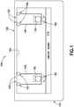
Figure 1 , one exemplary embodiment of an apparatus showing an integration of a microphone configuration therein is designated generally by thereference number 100 and is hereinafter referred to as "apparatus 100." Inapparatus 100, ahousing 120 includes a plurality ofholes 130 therein through which sound can be received. As shown, afirst microphone housing 140 and asecond microphone housing 145 may be located in thehousing 120, eachmicrophone housing first microphone 150 andsecond microphone 155, and eachmicrophone housing inner surface 160 of thehousing 120 such that sound may be received through one ormore holes 130 into thefirst microphone housing 140 and through one or moreadditional holes 130 into thesecond microphone housing 145. Thefirst microphone 150 may be operably coupled to acircuit board 170 via afirst connection 180, and thesecond microphone 155 may be operably coupled to thecircuit board 170 via asecond connection 185. One or both of thefirst connection 180 and thesecond connection 185 may be flexible, such as wiring through flexible tubing. Thefirst microphone 150 and thesecond microphone 155 are not limited to being operably coupled to thecircuit board 170, however, as the microphone(s) may be coupled to a chassis or any other element of theapparatus 100. - This integration of microphones into an apparatus generally involves a precision placement and coupling of the first microphone 150 (and the first microphone housing 140) to the second microphone 155 (and the second microphone housing 145). Precision placement of the
microphones microphones holes 130. Additionally, afirst seal 190 sealing thefirst microphone housing 140 to theinner surface 160 of thehousing 120 is separate from asecond seal 195 sealing thesecond microphone housing 145 to theinner surface 160 of thehousing 120 in order to avoid sound received in thefirst microphone housing 140 being "leaked" into thesecond microphone housing 145. However, precisely placing themicrophones microphone housings apparatus 100. - Referring to
Figure 2 , thefirst microphone housing 140 may comprisewalls 200 that extend perpendicularly from theinner surface 160 of thehousing 120, thewalls 200 configured to define asound cavity 210 and arranged to surround a plurality of theholes 130. Thewalls 200 may be sealed to theinner surface 160 using a suitable adhesive, ultrasonic welding, or any other suitable means of sealing, or they may be integrally formed with theinner surface 160 of thehousing 120. Thefirst microphone 150 in themicrophone housing 140 may be located distally from theholes 130 such that sound received into thesound cavity 210 has a particular quality. Thesecond microphone housing 145 may be similarly configured, or it may be configured to be different. - Referring to
Figure 3 , thefirst microphone 150 in thefirst microphone housing 140 may be operably coupled to thecircuit board 170 using aflexible member 300. As shown, theflexible member 300 may extend along joints defined bywalls 310 and theinner surface 160 of thehousing 120 as well as across theinner surface 160 of thehousing 120. - Referring to
Figure 4 , a configuration of theholes 130 in thehousing 120 is shown. Theholes 130 may be arranged in a rectangular array, as shown, or they may be arranged in a circular pattern, an oval pattern, or any other suitable pattern. - Referring now to
Figure 5 , another exemplary embodiment of an apparatus showing an integration of a microphone configuration therein is designated generally by thereference number 500 and is hereinafter referred to as "apparatus 500."Apparatus 500 may be a camera (e.g., a virtual reality (VR) camera, a camera having a wide-angle lens, a camera having multiple lenses, or the like), a tablet, a mobile phone, or the like. Although the features will be described with reference to the example embodiments shown in the drawings, it should be understood that features can be embodied in many alternate forms of embodiments. In addition, any suitable size, shape, or type of elements or materials could be used. -
Apparatus 500 comprises at least two microphones, namely, afirst microphone 550 and asecond microphone 555, each located on acircuit board 570 in achassis 510 and each capable of receiving sound waves (sound) from an environment outside theapparatus 500 and through ahousing 520 having a porosity. Thehousing 520 may be a cover having a porosity, such a cover being a lid or other member for the apparatus through which the sound may be received. Aprocessor 940 may be located on thecircuit board 570. Although theapparatus 500 is described as receiving the sound through thehousing 520 or cover, one of ordinary skill in the art would understand that thechassis 510 may also have a porosity and that sound may be received through thechassis 510. - The
apparatus 500 is configured to enable the capture of sound at thefirst microphone 550 and thesecond microphone 555. The sound may be received into theapparatus 500 through respective sound inlets in thehousing 520, the sound inlets being pores of a material from which thehousing 520 is fabricated. The sound inlets are too small to be discernible by the user (and are therefore substantially invisible). The sound inlets are also not mechanically coupled to thefirst microphone 550 or thesecond microphone 555 due to such mechanical coupling being generally difficult and expensive to manufacture, the sound inlets being easily blocked by the user's hand, and the sound inlets being sensitive to wind and handling noise. - In the
apparatus 500, thefirst microphone 550 and thesecond microphone 555 may be assembled directly to thecircuit board 570, thus obviating the need for a flexible connection of themicrophones circuit board 570. Each of thefirst microphone 550 and thesecond microphone 555 may include a microphone housing and front/back chambers as desired. Eachmicrophone first microphone 550 and thesecond microphone 555 may not be sealed (e.g., mechanically coupled) to aninner surface 560 of thehousing 520 to enable sound to be received through the same portion of thehousing 520 and picked up by either or bothmicrophones - Referring to
Figure 6 , thehousing 520 may be a porous structural element with the pores through which the sound is received being too small to be discernible. Thehousing 520 may be made of one or more different materials. In one exemplary embodiment, the material of thehousing 520 comprises aluminum having a porosity sufficient to allow for the passing of sound waves. Thehousing 520 is not limited to being aluminum, however, as other materials may be used (e.g., aluminum alloys, metal foams such as aluminum foam, and the like). In exemplary embodiments in which aluminum is used as the material for thehousing 520, the aluminum may have a porosity of 50% or greater and nominal pore sizes of about 50 micrometers (um) in diameter to about 600 um in diameter. In some exemplary embodiments, the nominal pore sizes are about 100 um in diameter. Furthermore, the pores may be tortuous throughout the aluminum (or other material) such that light does not pass through. Additionally, the porosity may be defined by an arrangement of pores that creates a design illusion that may or may not be detectable by the user. Thehousing 520 may also be of sufficient size such that the user cannot inadvertently block all of the sound received through thehousing 520. - The
housing 520 and the porosity thereof may have an effect on frequency characteristics of sound passing through thehousing 520. For example, the porosity, pore size, and/or material of thehousing 520 may cause higher frequencies to be attenuated more than lower frequencies. One or both of thefirst microphone 550 and thesecond microphone 555 may be configured to counter this effect by amplifying higher frequencies. Furthermore, it may be possible to counter this effect using the processor 940 (also shown inFigure 9 ) to filter or otherwise process an output from one or both of thefirst microphone 550 and thesecond microphone 555 using a digital filter. - Referring now to
Figure 7 , anair gap 700 is shown between amicrophone 550 and theinner surface 560 of thehousing 520. Themicrophone 550 may be disposed in a microphone housing and may be connected directly to thecircuit board 570, thus obviating the need for a flexible connection between themicrophone 550 and thecircuit board 570. Ahole 575 in thecircuit board 570 operates as an inlet and facilitates the passing of sound from theair gap 700 to themicrophone 550. In the alternative, the microphone 550 (and/or a second microphone) may be mounted to thecircuit board 570 on the side facing theinner surface 560 of thehousing 520. In any embodiment, however, themicrophone 550 may not be sealed to theinner surface 560 of thehousing 520. - Referring now to
Figure 8 , another exemplary embodiment of an apparatus showing an integration of a microphone configuration therein is designated generally by thereference number 800 and is hereinafter referred to as "apparatus 800."Apparatus 800 may be a camera (e.g., a VR camera), a tablet, a mobile phone, or the like. -
Apparatus 800 comprises one internal microphone, namely, amicrophone 850, located on acircuit board 870 and capable of receiving acoustic signals from an environment outside theapparatus 800 and through ahousing 820. As withapparatus 500, theapparatus 800 is configured to enable the capture of sound into themicrophone 850 through respective sound inlets in thehousing 820, the sound inlets in thehousing 820 being too small to be discernible (and therefore substantially invisible) and not mechanically coupled to themicrophone 850. Also as withapparatus 500, thehousing 820 inapparatus 800 may be porous. Materials from which thehousing 820 may be fabricated include, but are not limited to, aluminum, aluminum alloys, metal foams, and the like. As with theapparatus 500, themicrophone 850 may not be directly connected to aninner surface 860 of thehousing 820. - Referring now to
Figures 5 through 7 , themicrophones housing 520, such holes generally detracting from the aesthetic appearances of theapparatus 200, because theentire housing 520 is fabricated of the porous material with substantially non-discernible (virtually invisible) holes that audio can pass through. Furthermore, the user cannot block theentire housing 520 with their hands, and therefore themicrophones microphones circuit board 570, which is less expensive and generally more reliable than the use of seals, flex connections, and the like. Additionally, the porosity of thehousing 520 may contribute to a reduction in noise due to wind and/or other environmental factors, at least in some situations. Still further, handling noise may be reduced due to themicrophones housing 520. Similar advantages may be realized in an apparatus employing only one microphone. - Referring now to
Figure 9 , a method of receiving sound for use with a camera, VR camera, tablet, mobile phone, or other electronic device is shown generally at 900 and is hereinafter referred to as "method 900." Inmethod 900, sound is received through a porous housing of an electronic device, as shown instep 910. The sound is picked up by a microphone, as shown instep 920. Althoughstep 920 illustrates that the sound is picked up by one microphone, the sound may be picked up by two or more microphones located in or otherwise associated with the electronic device. The sound picked up by the microphone(s) may then be processed using acontroller 930 having aprocessor 940 and amemory 950. Thememory 950 may includesoftware 960 and may store the processed sound. Processed sound may then be used for any suitable application associated with the electronic device, e.g., as a sound file for recorded audio content, as filtered audio for a user of the electronic device or any other user to which the filtered audio is transferred, as a simple audio output, or the like. - A comparison simulation with ARES LPM (lumped parameter method) acoustic simulation tool (available from McIntosh Applied Engineering, LLC, Eden Prairie, Minnesota, USA) was performed. In a typical microphone integration, a microphone was integrated into a device housing, the microphone being a typical 3x4x1 millimeters (mm) MEMS (microelectrical-mechanical system) microphone such as a Knowles brand microphone (available from Knowles, Itasca, Illinois, USA). In such a microphone, the sound port length was 1 mm, and the sound port diameter was also 1 mm. A typical ideal integration in a high-quality audio device was achieved. As shown in
Figure 10 , a simulated response is shown generally at 1000. Thesimulated response 1000 has aresonance peak 1010 at 25 kilo Hertz (kHz), with the highest frequencies above that peak being attenuated. - A microphone integration with a porous metal surface, as with regard to the present exemplary embodiments described herein, was also performed. In such an integration, the same type of microphone as in Case A was integrated into a main printed wiring board (PWB) of a device. The device housing was 3x7x1 centimeters (cm) (the device was a small consumer electronics device (a camera)) having an open air volume of approximately 10% of the total cavity size, which was approximately 2 cubic centimeters. The housing of the device was made of porous metal and had small pores in the surfaces thereof, such pores operating as sound ports. A porosity of the metal was 50%, the material thickness was 0.5 mm, the pore size was 0.14 mm, and the number of pores was about 12,500. As shown in
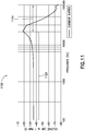
Figure 11 , a simulated response is shown generally at 1100, with simulated results showing that (1) simulated response had an equal overall sensitivity in therange 1110 as compared to a reference integration; and (2) simulated response had an equally flat frequency behavior in the operation range of 100 Hz to 20 kHz (shown at 1120). Therefore, according to the simulation, the acoustic parameters of the exemplary embodiment of the present invention would be as good as high quality prior art designs. - With regard to both Case A and Case B, the simulation results also revealed that putting microphones on the PWB and using one or a small number of holes in the housing instead of porous material would be detrimental to the operations of the apparatus. In the Case A scenario, if the microphone was integrated into the PWB and it was not mechanically coupled to the housing and the housing had a single large inlet tube (or a few smaller tubes) through the housing, results were less than optimal. However, in a Helmholz resonator the air in the tube corresponded to a resistance, and the air space between the housing and the PWB corresponded to a capacitance. The air space was large compared to the tube, and this pushed the resonance into lower frequencies that caused problems to the microphone frequency response. In the exemplary embodiments of the present invention as described herein, the large number of small pores effectively changed the ratio in the Helmholz resonator, and the problem disappeared even though the microphones were on the PWB and had no mechanical coupling to the housing. In practice, this may only work when a porous material is used, because only in a porous material enough pores (inlets) can be produced cheaply. Drilling or laser drilling substantial amounts of inlets may be prohibitively expensive.
- Referring now to all of the Figures and Examples described herein, any of the foregoing exemplary embodiments may be implemented in software, hardware, application logic, or a combination of software, hardware, and application logic. The software, application logic, and/or hardware may reside in the apparatus 500 (or
apparatus 800 or other device) to detect sound through a porous structure for subsequent processing. If desired, all or part of the software, application logic, and/or hardware may reside at any other suitable location. In an example embodiment, the application logic, software, or an instruction set is maintained on any one of various computer-readable media. A "computer-readable medium" may be any media or means that can contain, store, communicate, propagate, or transport instructions for use by or in connection with an instruction execution system, apparatus, or device, such as a computer. A computer-readable medium may comprise a computer-readable storage medium that may be any media or means that can contain or store the instructions for use by or in connection with an instruction execution system, apparatus, or device, such as a computer. - In one exemplary embodiment, an apparatus comprises a housing, the housing having a porosity comprising pores that are substantially non-discernible to a user such that sound waves from an outside of the housing can be received at an inside of the housing; at least one microphone located at the inside of the housing and configured to receive the sound waves via acoustic connection to the outside of the housing; a processor for processing the sound waves received by the at least one microphone; and a memory for storing the processed sound waves as a file. The at least one microphone is not mechanically coupled to the pores.
- In the apparatus, the at least one microphone may comprise at least two microphones. The porosity of the housing may be defined by pores from about 50 um in diameter to about 600 um in diameter. The porosity of the housing may be 50% or greater. A material of the housing may comprise aluminum. A material of the housing may be a metal. The at least one microphone may be configured to amplify a higher frequency of the sound waves received at the inside of the housing. The processor may further comprise a digital filter for filtering outputs from the at least one microphone to counter attenuation of higher frequencies of the sound waves received at the inside of the housing. The apparatus may be a camera, a virtual reality camera, a camera having a wide-angle lens, a camera having two or more lenses, a tablet, or a mobile phone.
- In another exemplary embodiment, an apparatus comprises at least one processor; and at least one non-transitory memory including computer program code, the at least one memory and the computer program code configured to, with the at least one processor, cause the apparatus at least to perform: detecting a sound from a first side of a porous material comprising pores that are substantially non-discernible to a user through the porous material at an opposing second side of the porous material; receiving the sound into at least one microphone at the opposing second side of the porous material via acoustic connection to the first side of the porous material; and processing the received sound at the at least one processor. The at least one microphone is not mechanically coupled to the pores.
- In the apparatus, the at least one microphone may comprise at least two microphones. A porosity of the porous material may be defined by pores from about 50 um in diameter to about 600 um in diameter. A porosity of the housing may be 50% or greater. A material of the housing may comprise aluminum. A material of the housing may be a metal.
- In another exemplary embodiment, a method comprises detecting a sound from a first side of a porous material comprising pores that are substantially non-discernible to a user through the porous material at an opposing second side of the porous material; receiving the sound into at least one microphone at the opposing second side of the porous material via acoustic connection to the first side of the porous material; and processing the received sound at the at least one processor. The at least one microphone is not mechanically coupled to the pores.
- In the method, a porosity of the porous material may be defined by pores from about 50 um in diameter to about 600 um in diameter. A material of the housing may comprise aluminum. The method may further comprise amplifying a higher frequency of the sound received at the opposing second side of the porous material. The method may further comprise means for filtering an output from one or more of the at least one microphone to counter attenuation of higher frequencies of the sound received at the opposing second side of the porous material.
- It should be understood that the foregoing description is only illustrative. Various alternatives and modifications can be devised by those skilled in the art. For example, features recited in the various dependent claims could be combined with each other in any suitable combination(s). In addition, features from different embodiments described above could be selectively combined into a new embodiment. Accordingly, the description is intended to embrace all such alternatives, modifications, and variances which fall within the scope of the appended claims.
Claims (15)
- An apparatus, comprising:a housing, the housing having a porosity comprising pores such that sound waves from an outside of the housing can be received at an inside of the housing through the pores;at least one microphone located at the inside of the housing and configured to receive the sound waves via acoustic connection to the outside of the housing by receiving the sound waves through the pores, from the inside of the housing, and across an air gap to the at least one microphone;a processor for processing the sound waves received by the at least one microphone; anda memory for storing the processed sound waves as a file or transferring the processed sound waves;wherein the at least one microphone is not mechanically coupled to the pores.
- The apparatus as claimed in claim 1, wherein the at least one microphone comprises at least two microphones.
- The apparatus as claimed in any of claims 1 and 2, wherein the porosity of the housing is defined by the pores from about 50 um in diameter to about 600 um in diameter.
- The apparatus as claimed in any of preceding claim, wherein the porosity of the housing is 50% or greater.
- The apparatus as claimed in any of preceding claim, wherein a material of the housing is a metal.
- The apparatus as claimed in claim 5, wherein the metal comprises aluminum.
- The apparatus as claimed in any of preceding claim, wherein the at least one microphone is configured to amplify a higher frequency of the sound waves received at the inside of the housing.
- The apparatus as claimed in any of preceding claim, wherein the processor further comprises a digital filter for filtering outputs from the at least one microphone to counter attenuation of higher frequencies of the sound waves received at the inside of the housing.
- The apparatus as claimed in any of preceding claim, wherein the apparatus is at least one of a camera, a virtual reality camera, a camera having a wide-angle lens, a camera having two or more lenses, a tablet, a mobile phone and an electronic device.
- The apparatus as claimed in claim 1, wherein the apparatus is configured to detect the sound waves from a first side of a porous material comprising the pores that are substantially non-discernible to a user through the porous material at an opposing second side of the porous material;
receiving the sound waves into at least one microphone at the opposing second side of the porous material via the acoustic connection to the first side of the porous material. - A method, comprising:detecting a sound from a first side of a porous material comprising pores that are substantially non-discernible to a user through the porous material at an opposing second side of the porous material;receiving the sound into at least one microphone at the opposing second side of the porous material via acoustic connection to the first side of the porous material; andprocessing the received sound at the at least one processor;wherein the at least one microphone is not mechanically coupled to the pores.
- The method as claimed in claim 11, wherein a porosity of the porous material is defined by the pores from about 50 um in diameter to about 600 um in diameter.
- The method as claimed in any of claims 11 and 12, wherein the porous material comprises aluminum.
- The method of any of claims 11 and 13, further comprising amplifying a higher frequency of the sound received at the opposing second side of the porous material.
- The method of any of claims 11 and 14, further comprising means for filtering an output from the at least one microphone to counter attenuation of higher frequencies of the sound received at the opposing second side of the porous material.
Applications Claiming Priority (1)
| Application Number | Priority Date | Filing Date | Title |
|---|---|---|---|
| US15/266,049 US20180077477A1 (en) | 2016-09-15 | 2016-09-15 | Porous audio device housing |
Publications (1)
| Publication Number | Publication Date |
|---|---|
| EP3297290A1 true EP3297290A1 (en) | 2018-03-21 |
Family
ID=59930163
Family Applications (1)
| Application Number | Title | Priority Date | Filing Date |
|---|---|---|---|
| EP17188922.3A Ceased EP3297290A1 (en) | 2016-09-15 | 2017-09-01 | Porous audio device housing |
Country Status (3)
| Country | Link |
|---|---|
| US (1) | US20180077477A1 (en) |
| EP (1) | EP3297290A1 (en) |
| CN (1) | CN107835467A (en) |
Families Citing this family (1)
| Publication number | Priority date | Publication date | Assignee | Title |
|---|---|---|---|---|
| CN110161457A (en) * | 2019-05-08 | 2019-08-23 | 绍兴文理学院元培学院 | A kind of moving sound positioning system and localization method |
Citations (6)
| Publication number | Priority date | Publication date | Assignee | Title |
|---|---|---|---|---|
| WO2001003468A2 (en) * | 1999-07-07 | 2001-01-11 | Gore Enterprise Holdings, Inc. | Acoustic protective cover assembly |
| GB2455300A (en) * | 2007-12-03 | 2009-06-10 | David Herman | Accurate ambient noise sensing and reduction of wind noise |
| WO2013106369A1 (en) * | 2012-01-09 | 2013-07-18 | Actiwave Ab | Integrated loudspeaker assemblies |
| US20140064545A1 (en) * | 2012-08-29 | 2014-03-06 | Apple Inc. | Systems and methods for enhancing performance of a microphone |
| WO2014049203A1 (en) * | 2012-09-28 | 2014-04-03 | Nokia Corporation | Porous cover structures for mobile device audio |
| US20140270206A1 (en) * | 2013-03-15 | 2014-09-18 | Timothy Alan PORT | Acoustic transmissivity impairment determining method and apparatus |
Family Cites Families (17)
| Publication number | Priority date | Publication date | Assignee | Title |
|---|---|---|---|---|
| US3588384A (en) * | 1968-12-16 | 1971-06-28 | Electro Voice | Headset incorporating a microphone and an earphone |
| US4570746A (en) * | 1983-06-30 | 1986-02-18 | International Business Machines Corporation | Wind/breath screen for a microphone |
| US4975966A (en) * | 1989-08-24 | 1990-12-04 | Bose Corporation | Reducing microphone puff noise |
| US4966252A (en) * | 1989-08-28 | 1990-10-30 | Drever Leslie C | Microphone windscreen and method of fabricating the same |
| WO2001037519A2 (en) * | 1999-11-19 | 2001-05-25 | Gentex Corporation | Vehicle accessory microphone |
| US20040202291A1 (en) * | 2002-08-27 | 2004-10-14 | Skinner Davey Nyle | Mobile phone with voice recording transfer function |
| US7106876B2 (en) * | 2002-10-15 | 2006-09-12 | Shure Incorporated | Microphone for simultaneous noise sensing and speech pickup |
| WO2005067653A2 (en) * | 2004-01-07 | 2005-07-28 | Logitech Europe S.A. | Porous solid wind screen for microphone |
| US20070003081A1 (en) * | 2005-06-30 | 2007-01-04 | Insound Medical, Inc. | Moisture resistant microphone |
| TWM281366U (en) * | 2005-07-26 | 2005-11-21 | Yung-Chuan Wen | Telescopic pickup apparatus enabling to augment physical volume gain and pick up unidirectional audio source |
| US20080159558A1 (en) * | 2006-12-28 | 2008-07-03 | Fortemedia, Inc. | Internal microphone array or microphone module not affecting appearance of electronic device |
| JP2009044600A (en) * | 2007-08-10 | 2009-02-26 | Panasonic Corp | Microphone device and manufacturing method thereof |
| US8036716B2 (en) * | 2008-02-04 | 2011-10-11 | Motorola Solutions, Inc. | Temporary storage or specialized transmission of multi-microphone signals |
| US8229153B2 (en) * | 2008-04-01 | 2012-07-24 | Apple Inc. | Microphone packaging in a mobile communications device |
| US8515113B2 (en) * | 2010-08-19 | 2013-08-20 | Apple Inc. | Composite microphone boot to optimize sealing and mechanical properties |
| US9414141B2 (en) * | 2012-01-04 | 2016-08-09 | Apple Inc. | Mesh structure providing enhanced acoustic coupling |
| CN105765992B (en) * | 2013-11-18 | 2019-08-20 | 日东电工株式会社 | Waterproof sound passing membrane and the water-proof sound-transmitting structure for using waterproof sound passing membrane |
-
2016
- 2016-09-15 US US15/266,049 patent/US20180077477A1/en not_active Abandoned
-
2017
- 2017-09-01 EP EP17188922.3A patent/EP3297290A1/en not_active Ceased
- 2017-09-14 CN CN201710828451.8A patent/CN107835467A/en active Pending
Patent Citations (6)
| Publication number | Priority date | Publication date | Assignee | Title |
|---|---|---|---|---|
| WO2001003468A2 (en) * | 1999-07-07 | 2001-01-11 | Gore Enterprise Holdings, Inc. | Acoustic protective cover assembly |
| GB2455300A (en) * | 2007-12-03 | 2009-06-10 | David Herman | Accurate ambient noise sensing and reduction of wind noise |
| WO2013106369A1 (en) * | 2012-01-09 | 2013-07-18 | Actiwave Ab | Integrated loudspeaker assemblies |
| US20140064545A1 (en) * | 2012-08-29 | 2014-03-06 | Apple Inc. | Systems and methods for enhancing performance of a microphone |
| WO2014049203A1 (en) * | 2012-09-28 | 2014-04-03 | Nokia Corporation | Porous cover structures for mobile device audio |
| US20140270206A1 (en) * | 2013-03-15 | 2014-09-18 | Timothy Alan PORT | Acoustic transmissivity impairment determining method and apparatus |
Also Published As
| Publication number | Publication date |
|---|---|
| US20180077477A1 (en) | 2018-03-15 |
| CN107835467A (en) | 2018-03-23 |
Similar Documents
| Publication | Publication Date | Title |
|---|---|---|
| EP3056017B1 (en) | Pressure vent for speaker or microphone modules | |
| CN109845289A (en) | Detect the presence of wind noise | |
| KR102116156B1 (en) | Noise mitigating microphone attachment | |
| US10631073B2 (en) | Microphone housing with screen for wind noise reduction | |
| EP3190809A1 (en) | Micro-speaker having an air adsorbent with a binder | |
| CN105049966A (en) | Evacuation of liquid from acoustic space | |
| TWI468023B (en) | Wind noise rejection apparatus | |
| US10057670B2 (en) | Apparatus and method for providing an apparatus comprising an audio transducer | |
| US11277688B2 (en) | Apparatus, method and computer program for audio module use in an electronic device | |
| US9661412B2 (en) | Apparatus for providing passive stereo amplification for a portable device | |
| EP2285135A1 (en) | Microphone-speaker device comprising a low pass filter | |
| WO2015089063A1 (en) | Remote speaker microphone | |
| US20170111731A1 (en) | Microphone assembly with suppressed frequency response | |
| US8848963B2 (en) | Microphone arrangement for a breathing mask | |
| US9872094B2 (en) | Speaker coupling and bracket | |
| CN111182402A (en) | Noise reduction processing method for earphone, earphone and computer readable storage medium | |
| CN104685902B (en) | The acoustical back chamber system of sound transducer | |
| US10109292B1 (en) | Audio systems with active feedback acoustic echo cancellation | |
| KR102036752B1 (en) | Waterproof sound-transmitting structure and electronic device | |
| EP3297290A1 (en) | Porous audio device housing | |
| CN207588947U (en) | Housing unit and the mobile terminal for including it | |
| CN109788409A (en) | Micro-speaker assemblies with manual pump | |
| US11297411B2 (en) | Microphone units with multiple openings | |
| KR20230150423A (en) | A microspeaker module |
Legal Events
| Date | Code | Title | Description |
|---|---|---|---|
| PUAI | Public reference made under article 153(3) epc to a published international application that has entered the european phase |
Free format text: ORIGINAL CODE: 0009012 |
|
| STAA | Information on the status of an ep patent application or granted ep patent |
Free format text: STATUS: THE APPLICATION HAS BEEN PUBLISHED |
|
| AK | Designated contracting states |
Kind code of ref document: A1 Designated state(s): AL AT BE BG CH CY CZ DE DK EE ES FI FR GB GR HR HU IE IS IT LI LT LU LV MC MK MT NL NO PL PT RO RS SE SI SK SM TR |
|
| AX | Request for extension of the european patent |
Extension state: BA ME |
|
| STAA | Information on the status of an ep patent application or granted ep patent |
Free format text: STATUS: REQUEST FOR EXAMINATION WAS MADE |
|
| 17P | Request for examination filed |
Effective date: 20180920 |
|
| RBV | Designated contracting states (corrected) |
Designated state(s): AL AT BE BG CH CY CZ DE DK EE ES FI FR GB GR HR HU IE IS IT LI LT LU LV MC MK MT NL NO PL PT RO RS SE SI SK SM TR |
|
| STAA | Information on the status of an ep patent application or granted ep patent |
Free format text: STATUS: EXAMINATION IS IN PROGRESS |
|
| 17Q | First examination report despatched |
Effective date: 20190130 |
|
| STAA | Information on the status of an ep patent application or granted ep patent |
Free format text: STATUS: EXAMINATION IS IN PROGRESS |
|
| RAP1 | Party data changed (applicant data changed or rights of an application transferred) |
Owner name: NOKIA TECHNOLOGIES OY |
|
| STAA | Information on the status of an ep patent application or granted ep patent |
Free format text: STATUS: THE APPLICATION HAS BEEN REFUSED |
|
| 18R | Application refused |
Effective date: 20210422 |