EP3297148A1 - Method for the reformation of an electrolytic capacitor in a converter and converter with such - Google Patents
Method for the reformation of an electrolytic capacitor in a converter and converter with such Download PDFInfo
- Publication number
- EP3297148A1 EP3297148A1 EP17190356.0A EP17190356A EP3297148A1 EP 3297148 A1 EP3297148 A1 EP 3297148A1 EP 17190356 A EP17190356 A EP 17190356A EP 3297148 A1 EP3297148 A1 EP 3297148A1
- Authority
- EP
- European Patent Office
- Prior art keywords
- intermediate circuit
- voltage
- capacitor
- converter
- grid
- Prior art date
- Legal status (The legal status is an assumption and is not a legal conclusion. Google has not performed a legal analysis and makes no representation as to the accuracy of the status listed.)
- Withdrawn
Links
Images


Classifications
-
- H—ELECTRICITY
- H01—ELECTRIC ELEMENTS
- H01G—CAPACITORS; CAPACITORS, RECTIFIERS, DETECTORS, SWITCHING DEVICES OR LIGHT-SENSITIVE DEVICES, OF THE ELECTROLYTIC TYPE
- H01G11/00—Hybrid capacitors, i.e. capacitors having different positive and negative electrodes; Electric double-layer [EDL] capacitors; Processes for the manufacture thereof or of parts thereof
- H01G11/14—Arrangements or processes for adjusting or protecting hybrid or EDL capacitors
- H01G11/20—Reformation or processes for removal of impurities, e.g. scavenging
-
- H—ELECTRICITY
- H02—GENERATION; CONVERSION OR DISTRIBUTION OF ELECTRIC POWER
- H02J—CIRCUIT ARRANGEMENTS OR SYSTEMS FOR SUPPLYING OR DISTRIBUTING ELECTRIC POWER; SYSTEMS FOR STORING ELECTRIC ENERGY
- H02J7/00—Circuit arrangements for charging or depolarising batteries or for supplying loads from batteries
-
- H—ELECTRICITY
- H02—GENERATION; CONVERSION OR DISTRIBUTION OF ELECTRIC POWER
- H02M—APPARATUS FOR CONVERSION BETWEEN AC AND AC, BETWEEN AC AND DC, OR BETWEEN DC AND DC, AND FOR USE WITH MAINS OR SIMILAR POWER SUPPLY SYSTEMS; CONVERSION OF DC OR AC INPUT POWER INTO SURGE OUTPUT POWER; CONTROL OR REGULATION THEREOF
- H02M5/00—Conversion of ac power input into ac power output, e.g. for change of voltage, for change of frequency, for change of number of phases
- H02M5/40—Conversion of ac power input into ac power output, e.g. for change of voltage, for change of frequency, for change of number of phases with intermediate conversion into dc
- H02M5/42—Conversion of ac power input into ac power output, e.g. for change of voltage, for change of frequency, for change of number of phases with intermediate conversion into dc by static converters
- H02M5/44—Conversion of ac power input into ac power output, e.g. for change of voltage, for change of frequency, for change of number of phases with intermediate conversion into dc by static converters using discharge tubes or semiconductor devices to convert the intermediate dc into ac
- H02M5/453—Conversion of ac power input into ac power output, e.g. for change of voltage, for change of frequency, for change of number of phases with intermediate conversion into dc by static converters using discharge tubes or semiconductor devices to convert the intermediate dc into ac using devices of a triode or transistor type requiring continuous application of a control signal
- H02M5/458—Conversion of ac power input into ac power output, e.g. for change of voltage, for change of frequency, for change of number of phases with intermediate conversion into dc by static converters using discharge tubes or semiconductor devices to convert the intermediate dc into ac using devices of a triode or transistor type requiring continuous application of a control signal using semiconductor devices only
- H02M5/4585—Conversion of ac power input into ac power output, e.g. for change of voltage, for change of frequency, for change of number of phases with intermediate conversion into dc by static converters using discharge tubes or semiconductor devices to convert the intermediate dc into ac using devices of a triode or transistor type requiring continuous application of a control signal using semiconductor devices only having a rectifier with controlled elements
-
- H—ELECTRICITY
- H02—GENERATION; CONVERSION OR DISTRIBUTION OF ELECTRIC POWER
- H02J—CIRCUIT ARRANGEMENTS OR SYSTEMS FOR SUPPLYING OR DISTRIBUTING ELECTRIC POWER; SYSTEMS FOR STORING ELECTRIC ENERGY
- H02J7/00—Circuit arrangements for charging or depolarising batteries or for supplying loads from batteries
- H02J7/34—Parallel operation in networks using both storage and other dc sources, e.g. providing buffering
- H02J7/345—Parallel operation in networks using both storage and other dc sources, e.g. providing buffering using capacitors as storage or buffering devices
-
- Y—GENERAL TAGGING OF NEW TECHNOLOGICAL DEVELOPMENTS; GENERAL TAGGING OF CROSS-SECTIONAL TECHNOLOGIES SPANNING OVER SEVERAL SECTIONS OF THE IPC; TECHNICAL SUBJECTS COVERED BY FORMER USPC CROSS-REFERENCE ART COLLECTIONS [XRACs] AND DIGESTS
- Y02—TECHNOLOGIES OR APPLICATIONS FOR MITIGATION OR ADAPTATION AGAINST CLIMATE CHANGE
- Y02E—REDUCTION OF GREENHOUSE GAS [GHG] EMISSIONS, RELATED TO ENERGY GENERATION, TRANSMISSION OR DISTRIBUTION
- Y02E10/00—Energy generation through renewable energy sources
- Y02E10/70—Wind energy
- Y02E10/76—Power conversion electric or electronic aspects
-
- Y—GENERAL TAGGING OF NEW TECHNOLOGICAL DEVELOPMENTS; GENERAL TAGGING OF CROSS-SECTIONAL TECHNOLOGIES SPANNING OVER SEVERAL SECTIONS OF THE IPC; TECHNICAL SUBJECTS COVERED BY FORMER USPC CROSS-REFERENCE ART COLLECTIONS [XRACs] AND DIGESTS
- Y02—TECHNOLOGIES OR APPLICATIONS FOR MITIGATION OR ADAPTATION AGAINST CLIMATE CHANGE
- Y02E—REDUCTION OF GREENHOUSE GAS [GHG] EMISSIONS, RELATED TO ENERGY GENERATION, TRANSMISSION OR DISTRIBUTION
- Y02E60/00—Enabling technologies; Technologies with a potential or indirect contribution to GHG emissions mitigation
- Y02E60/13—Energy storage using capacitors
Definitions
- the present invention relates to a method for the reformation of an intermediate circuit capacitor of a converter formed from at least one electrolytic capacitor and an associated converter for converting an AC grid voltage to a direct voltage or vice versa.
- Converters for converting alternating current to direct current and vice versa are used in many applications, for example, for coupling electrical grids with variable-speed drives, for energy exchange between two electrical grids, for photovoltaic and wind power plants and the like.
- power converters in different circuit topologies and configurations for different power and voltage ranges are known.
- multipoint converters are increasingly used, which have a circuit arrangement with controllable switching elements, preferably power semiconductor switches, which can be clocked at high frequencies to generate a plurality of voltage levels and handle higher voltages than the blocking capability of a single power semiconductor switch permits.
- Some converters on the DC voltage side comprise a so-called DC voltage intermediate circuit with an intermediate circuit capacitor arranged therein.
- an intermediate circuit capacitor is arranged between the grid-side rectifier and the load-side inverter and connected in parallel.
- the capacity of the intermediate circuit capacitor is substantial.
- series connections and/or parallel connections of capacitors preferably electrolytic capacitors, are generally used to provide the required dielectric strength and to be able to store large charge quantities.
- Such series and/or parallel connections of electrolytic capacitors are referred to herein as the "intermediate circuit capacitor" in the same manner as a single capacitor.
- Electrolytic capacitors are polarized capacitors whose anode electrode is made of a metal, in the case of aluminum electrolytic capacitors, for example, aluminum, to which an oxide layer is applied electrochemically as insulating layer, which forms the dielectric medium of the capacitor.
- the electrolyte is the cathode of the electrolytic capacitor.
- the quality of the oxide that changes repeatedly in the course of the electrolytic capacitor production and subsequent use, determines the insulating properties of the dielectric medium. With prolonged storage of electrolytic capacitors in voltage-free condition, especially at elevated temperatures, or due to aging, the oxide degenerates, so that its DC conductivity increases.
- the residual current which flows as a leakage current through the capacitor, may be relatively high shortly after applying a direct voltage.
- a very high residual current can lead to the destruction of the electrolytic capacitors of the intermediate circuit capacitor.
- the repetition of the forming process is referred to herein as reformation or reforming.
- the reformation process can only be started when all the above measures have been taken.
- the reformation requires the use of highly qualified, trained personnel, and is time-consuming, costly and prone to human error. Due to the possibility of human errors, it presents a risk to human health of the maintenance staff and the proper functioning of the system.
- Converters with an intermediate circuit capacitor of high capacitance cannot be connected to the grid without taking special measures, since the switch-on current could be excessively high. Such a switch-on current surge could damage or destroy the converter and the intermediate circuit capacitor. In case of adverse circuit impedances, too high a voltage can arise in the intermediate circuit capacitor, and adverse repercussions of the switch-on current surge on the supplying grid are possible.
- converters in particular frequency converters, usually comprise a precharging circuit for the intermediate circuit capacitor.
- a precharging circuit for the converter known from practice essentially comprises a switching device, a precharging resistor and an uncontrolled rectifier, which are arranged in series with each other on a current path between the supply grid and the intermediate circuit capacitor.
- the rectifier can be an uncontrolled rectifier whose converter valves are diodes connected similar to a Graetz bridge.
- the contacts on the AC voltage side of the switching device are connected to the supply grid.
- the output of the rectifier is connected to the DC voltage intermediate circuit.
- the switching device of the precharging circuit can be disconnected and the converter connected to the supply grid via a contactor so that the converter-powered intermediate circuit capacitor is now directly on the supplying grid. Then, the normal converter operation can be taken up.
- a further task of the invention is to create a converter comprising such an implemented method.
- a method for the reformation of an intermediate circuit capacitor of a converter formed from at least one electrolytic capacitor having the characteristics of independent claim 1, using a precharging circuit for a converter according to claim 18 and a converter for converting an AC grid voltage into a direct voltage or vice versa according to claim 19.
- Advantageous embodiments of the invention are the subject matter of the dependent claims.
- a method for the reformation of an intermediate circuit capacitor of a converter formed from at least one electrolytic capacitor, which is connected to a supply grid.
- the method comprises the provision of a precharging circuit for the converter, which is configured to precharge the intermediate circuit capacitor of the converter using a grid current of the supply grid, before the converter is connected to a supply grid.
- the precharging circuit comprises a switching device on a current path between the supply grid and the intermediate circuit capacitor.
- the method further comprises a receipt of a request for the reformation of the intermediate circuit capacitor.
- the method also comprises the switching of the switching device to a closed state on the receipt of the request for the reformation in order to allow a reformation current to flow from the supply grid through the closed switching device and the current path to the intermediate circuit capacitor in order to reform the intermediate circuit capacitor via the precharging circuit.
- the already existing precharging circuit for the converter in particular frequency converters, is thus used, if required, to reform the electrolytic capacitor(s) which form the intermediate circuit capacitor of the converter.
- Existing converters that comprise the precharging circuit can be supplemented by a software module for the reformation of the intermediate circuit capacitor, which otherwise uses the existing hardware to precharge the intermediate circuit capacitor to also achieve a reformation of the same.
- a single such precharging and reformation circuit can serve both purposes. Reformation with simple means can be performed quickly and easily.
- the need for human operation, in particular the use of qualified personnel can be significantly reduced or even eliminated, with the advantage that the associated risks to the maintenance staff and/or the system are reduced or even eliminated. Also, the maintenance staff does not have to access the intermediate circuit capacitor lines. Many of the protection measures required for conventional reformation processes for electrolytic capacitors of converters can be omitted.
- a reformation process would have to be initiated depending on the fulfillment of one or more conditions, e.g. when using the intermediate circuit capacitor after exceeding a specified storage period or non-use of the converter device.
- Other possible criteria for initiating a reformation process such as a direct or indirect evaluation of the level of the leakage current, can be used in addition or as a sole criterion.
- the provision of a precharging circuit can comprise the provision of a precharging circuit that further comprises a precharging resistor, which is connected in series to the switching device on the current path between the supply grid and the intermediate circuit capacitor, wherein, during the reformation, the precharging resistor limits a current flow through the current path to the intermediate circuit capacitor.
- the precharging resistor can also be used advantageously as a reformation resistor to suitably predetermine the reformation current and the reformation voltage.
- the precharging and reformation circuit is designed at low cost and comprises only a few cost-efficient components.
- the precharging circuit preferably also comprises a rectifier circuit to convert the AC grid voltage to a direct voltage, wherein the amount of the AC grid voltage, the control factor of the switching device as well as the leakage current of the electrolytic capacitor(s) to be reformed determine the reformation voltage for the capacitors during the reformation.
- the rectifier circuit is preferably an uncontrolled rectifier circuit, for example, based on a Graetz circuit, which gives a slightly pulsating DC output voltage.
- a controlled rectifier circuit could also be used, but is more complex and more costly in implementation and in operation.
- the receipt of a request for the reformation of the intermediate circuit capacitor comprises a receipt of a system-internal request signal triggered by an internal control device that is emitted when the control device detects conditions which are a necessary requirement for a reformation of the intermediate circuit capacitor.
- the control device can start the reformation process automatically, i.e. is self-activating, without the user's intervention.
- the internal system software of the converter, in particular the control software thus notifies when a reformation is necessary and triggers it when necessary.
- the detection of conditions that indicate a need for a reformation of the intermediate circuit capacitor can, in particular, comprise that it is determined when the intermediate circuit capacitor has received no power for a period of time that exceeds a predetermined first period of time. If the intermediate circuit capacitor has not been charged for a longer period of time, for example, because the converter was inactive for a prolonged time, this can indicate the need for a reformation.
- the predetermined first period of time depends on the respective electrolytic capacitor, and can be in the range of some weeks or months.
- the duration of the inactive time of the converter can be determined and stored in a data storage associated with the system software, to be used when examining the need for a reformation.
- the detection of conditions that indicate a need for a reformation of the intermediate circuit capacitor can comprise that it is detected when at least one of the electrolytic capacitors forming the intermediate circuit capacitor has been replaced.
- An exchange of the electrolytic capacitor can be recognized automatically by the system, for example, by the system software querying a circuit board carrying the electrolytic capacitors.
- a maintenance technician can also note the exchange of one or a plurality of electrolytic capacitors by setting an appropriate parameter in the database or software of the system of the converter, so that the system software subsequently detects that a reformation is necessary.
- the detection of conditions that indicate a need for a reformation of the intermediate circuit capacitor can comprise that it is determined that a precharging process for precharging the intermediate circuit capacitor by means of the precharging circuit is not completed within a period of time, which exceeds a predetermined second period of time.
- An excessive duration of the precharging process can indicate that the leakage current of the intermediate circuit capacitor is too high, and therefore a reformation is necessary.
- the second period of time can be determined empirically depending on the electrolyte capacitors and the precharging parameters used.
- the receipt of a request for the reformation of the intermediate circuit capacitor can comprise a receipt of an external request signal triggered by an operator.
- a maintenance technician can start a reformation process after replacing one or a plurality of electrolytic capacitors or carrying out maintenance or servicing work. The reformation process as such is subsequently performed and controlled by the control device of the converter without further intervention by the operator.
- the reformation process can be advantageously controlled taking into account a specification or recommendation provided by the respective manufacturer of the at least one electrolytic capacitor forming the intermediate circuit capacitor.
- manufacturer's specifications and recommendations on the reformation current, the reforming times and characteristic curves can preferably be stored in the system software or in an internal database of the converter, which can be accessed by the software or control, similarly to a lookup table, sorted by manufacturer, electrolytic capacitor type or the like, and used for the reformation process. Different manufacturers and electrolytic capacitor types can be taken into account. In simplified embodiments, only the reformation specifications or recommendations of the individual electrolytic capacitor type used in the respective converter are stored.
- the switching device of the precharging and reformation circuit during the reformation process can be clocked so that, on average, a desired reformation voltage on the intermediate circuit capacitor and/or a desired reformation current on the intermediate circuit capacitor results or result.
- the switching device can, for example, be switched on and off with pulse-width modulation with a predefined or varying clock ratio to achieve an average reformation voltage or an average reformation current which is less than the maximum permissible reformation voltage or the maximum permissible reformation current according to the manufacturer's specifications.
- a standard reformation process with a fixed clock ratio of the switching device or with a permanently switched-on switching device can be performed, regardless of the electrolytic capacitor type or manufacturer.
- the switching device can be clocked so that an average reformation voltage applied to the intermediate circuit capacitor follows a given reformation curve or characteristic curve.
- This reformation curve is usually dependent on the capacitor manufacturer and type, the storage time and the storage temperature.
- the applied average reformation voltage can be increased gradually in preferred embodiments to take into account the increasing regeneration of the oxide layer of the electrolytic capacitor and the increasing charge of the same.
- the switching device is clocked so that a medium reformation voltage applied to the intermediate circuit capacitor is increased gradually, wherein, between each number of cycle times within one voltage level and/or between successive voltage levels of the medium reformation voltage, the switching device is switched off for a predetermined period of time to interrupt a reformation current to the intermediate circuit capacitor.
- the reformation process is thus carried out intermittently, with an increasing reformation voltage. Such breaks in the reformation process allow the electrolytic capacitors to discharge slightly, via the leakage current, and can be used to estimate the leakage current and the progress of the reformation.
- the reformation progress can be monitored or controlled advantageously.
- the reformation process can then be optimized as required, depending on the actual operating conditions. In principle, the leakage current of the intermediate circuit capacitor could also be measured directly, which is less preferred due to the corresponding expense.
- the reformation process can also be used to detect a defect in the intermediate circuit capacitor, the converter or the precharging circuit. If, for example, it is found that the reformation process takes longer than a predefinable third period of time or the intermediate circuit voltage via the intermediate circuit capacitor is insufficient or does not increase sufficiently fast, this can be that indicate a hardware fault, and the reformation process can be aborted. Subsequently, an error message, for example, an optical or acoustic signal indicator on the converter system, can be output or transmitted to a remote center. In the event of a fault, measures can be taken to prevent the operation of the converter, in particular when connecting the converter to the supply grid.
- the switching device of the precharging circuit can be converted to an open state, in order to effectively disconnect the latter from the supply grid. After that, by closing a line disconnector, the converter can be connected to the supply grid.
- a precharging process for the intermediate circuit capacitor can be performed.
- the intermediate circuit capacitor can be charged to the required nominal voltage for the operation of the converter.
- the precharging process can also be triggered by an operator, for example by a maintenance technician.
- the converter is a frequency converter configured to exchange electrical energy between an AC voltage supply grid and an electrical machine.
- the electrical machine can be operated either as a motor or as a generator. Accordingly, the exchange of the electrical energy can occur either from the grid to the machine or vice versa.
- the method is used for a frequency converter which supplies a wind power plant generator.
- Another aspect of the invention provides a use of a precharging circuit for a converter, which is configured to precharge an intermediate circuit capacitor of the converter formed from at least one electrolytic capacitor by using a grid current from a supply grid before the converter is connected to the supply grid for the reformation of at least one electrolytic capacitor of the intermediate circuit capacitor.
- the embodiments and advantages of using the precharging circuit for the reformation process according to the invention can correspond to the embodiments and advantages of the reformation process according to the invention as described above.
- a modular multilevel converter for converting an AC grid voltage to a direct voltage and/or vice versa.
- the converter comprises a circuit arrangement with controllable switching elements, preferably power semiconductor switches, a DC voltage intermediate circuit, a precharging circuit and a control device.
- the DC voltage intermediate circuit is arranged on the DC voltage side of the circuit and connected in parallel with it, wherein the DC voltage intermediate circuit comprises an intermediate circuit capacitor formed by one or a plurality of interconnected electrolytic capacitors.
- the precharging circuit is configured to precharge the intermediate circuit capacitor of the converter using a grid current of the supply grid, before the converter is connected to the supply grid.
- the precharging circuit comprises a switching device on a current path between the supply grid and the intermediate circuit capacitor.
- the control device is used to control the operation of the converter depending on the detected operating conditions, wherein said control device is configured to perform a reformation process as described above.
- the converter may comprise the further developments and advantages mentioned above in connection with the reformation process.
- a preferred converter is a frequency converter for operating an electrical machine in an electrical supply grid, comprising a rectifier unit and an inverter unit, which are coupled to each other via the DC voltage intermediate circuit with the intermediate circuit capacitor.
- the frequency converter is preferably configured for use in a wind power plant to supply a wind power plant generator.
- Such frequency converters may already comprise a precharging circuit, as described above, which can be used advantageously to implement a reformation process for the electrolytic capacitors, which is simple, cost-effective and safe to use for personnel and the system.
- Existing converter systems can easily be retrofitted with the necessary control software to implement the reformation method.
- a precharging process as well as a reformation process can be implemented advantageously with a single hardware device.
- Fig. 1 shows, in a simplified representation, a system 1, which is suitable in particular for supplying machines for example, drive motors, generators or the like, but also for other applications for example, medium or high-voltage direct current power distribution systems for electrical energy transmission, isolated grid systems or the like.
- System 1 here comprises an exemplary three-phase AC voltage source 2, which can in particular be an electrical power grid or wind power plant, in principle also an alternating current (AC) machine, an AC generator or the like, and which hereinafter is simply referred to as the supply grid or grid 2.
- a converter system 4 which is connected on one side to a load 6 such as an electrical motor or a generator, is connected to the grid 2 via a transformer 3.
- the load 6 may represent a wind power plant generator and the converter system 4 may be a frequency converter system, which converts the AC grid voltage of the supply grid 2, which for example can be in the medium-voltage range of 10-20 kV, and which is lowered by the transformer 3 to a voltage level of, for example, 400-800 V, into an alternating voltage with a frequency that is suitable to supply a wind power plant generator 6.
- the transformer can also be omitted.
- the converter system 4 may be configured either for rectification only or for inversion only.
- the illustrated system 1 is shown as a three-phase system in which the respective phases are not shown separately but only together, as indicated by the slash with the numeral "3" above each of the three-phase lines in the system 1, shown by customary notation.
- the converter system 4 is connected to the grid 2 through a main switching device 7, which is a circuit-breaker device, which makes it possible, if necessary, or in case of errors for example, high overload or short-circuit currents, to galvanically disconnect the converter system 4 from the grid 2.
- a main switching device 7 which is a circuit-breaker device, which makes it possible, if necessary, or in case of errors for example, high overload or short-circuit currents, to galvanically disconnect the converter system 4 from the grid 2.
- the converter system 2 in the highly simplified representation of the embodiment shown, comprises substantially a first path or main current path 8, a second current path 9, a measuring device 11 and a control device 12.
- the first current path 8 extends between the circuit breaker device 7 and the load 6 and comprises a line disconnector 13, a frequency converter 14 and an interconnected grid choke 15.
- the line disconnector 13 is arranged between the main switching device 7 and the grid choke 15 to be able to disconnect the frequency converter 14 from the grid if needed or in case of error, even when the main switching device 7 is closed. While the main switching device 7 can be switched, for example, from a remote control center, the line disconnector 13 is controlled by the converter-internal control device 12, indicated by the control path 16 shown as a dashed arrow.
- the frequency inverter 14 is used to convert the AC input voltage present at input 17 shown in Fig. 1 into an AC output voltage with fitting frequency and amplitude at its output 18 to supply the load 6.
- the frequency converter 14 can be divided modularly or functionally in a rectifier unit 19, which converts the AC input voltage into an intermediate circuit DC voltage U ZK on a DC voltage intermediate circuit 21, and an inverter unit 22, which converts the intermediate circuit DC voltage U ZK into the AC output voltage.
- the inverter unit 22 is connected in parallel with the rectifier unit 19 to the DC voltage intermediate circuit 21.
- the frequency converter 14 is a converter that comprises, in the forward direction, switchable power semiconductor devices and backward conductive valves. More precisely, a circuit arrangement of controllable elements 23, commonly power semiconductor switches such as bipolar transistors with insulated gate electrode (IGBTs), as illustrated, is provided in the rectifier unit 19 and the inverter unit 22 to perform the respective rectifier or inverter functions. Instead of IGBTs, also MOSFETs, gate turn-off thyristors (GTOs), IGC thyristors (integrated gate-commutated thyristors, IGCTs) and other comparable switchable electronic power devices can be used.
- the controllability of the power semiconductor switches 23, the rectifier unit 19 and the inverter unit 22 in Fig. 1 is indicated by the control paths 16 shown as dashed arrows, which point from the control device 12 to the units 19, 22.
- the rectifier unit 19 and the inverter unit 22 comprise associated intermediate circuit capacitors 24a or 24b, which define the DC voltage intermediate circuit 21.
- the intermediate circuit capacitor 24a is connected at the output of the rectifier unit 19 between a positive and a negative DC voltage line 26, 27 of the DC voltage intermediate circuit 21, while the intermediate circuit capacitor 24b of the inverter unit 22 is connected in parallel to the intermediate circuit capacitor 24a at the input of the inverter unit 22 to its circuit arrangement.
- the intermediate circuit capacitors 24a, 24b are shown separately in the modular design shown, but can be grouped into a single intermediate circuit capacitor 24.
- each intermediate circuit capacitor 24a, 24b comprises a series connection and, where appropriate, a parallel circuit of a plurality of electrolytic capacitors, which are connected together to produce the required dielectric strength and storage capacity.
- an intermediate circuit capacitor 24 such series and/or parallel connections of electrolytic capacitors are hereinafter referred to as an intermediate circuit capacitor 24.
- the second current path 9 runs from a connection point 28 between the main switching device 7 and the line disconnector 13 of the first current path 8 to the DC voltage intermediate circuit 21.
- the second current path 9 comprises a precharging circuit 29, which is used to precharge the intermediate circuit capacitor 24 to the required DC voltage level before connecting the frequency inverter 14 to the grid 2, to avoid high transient switch-on currents, which could otherwise result in the discharging of the intermediate circuit capacitor 24.
- the precharging circuit 29 comprises a switching device 31, a precharging resistor 32 and an uncontrolled rectifier circuit 33, which are connected in series on the second current path 9.
- the rectifier circuit 33 is connected on the output side via a first connection line 34 with the positive DC voltage line 26 of the DC voltage intermediate circuit 21, and via a second connection line 36 with the negative DC voltage line 27.
- the precharging circuit 29 is shown in greater detail in Fig. 2 .
- the connection line 37 is shown, which connects the precharging circuit 29 with the connection point 28 and further with the grid 2.
- a contactor 38 is arranged in the three-phase connection line 37, which forms the switching device 31 and comprises switching contacts 39a-39c to interrupt or close all phase lines 37a-c of the connection line 37 simultaneously as required.
- the resistors 32a-c are provided, which are inserted between the switching contacts 39a-39c of the contactor 38 and AC voltage connections 41a-c of the rectifier circuit 33 and form the precharging resistor 32 according to Fig. 1 .
- the uncontrolled rectifier circuit 33 is designed similar to a Graetz bridge, with diodes D1-D6 as converter valves.
- a pair of rectifier diodes D1 and D2, D3 and D4 or D5 and D6 is arranged, each in series, between the first and the second connection line 34, 36, in the flow direction to the first connection line 34, while the connection points of the series-connected rectifier diodes D1 and D2, D3 and D4 or D5 and D6 form the AC voltage connections 41a-c.
- the cathodes of the rectifier diodes D1, D3 and D5 are connected to each other and to the first connection line 34, while the anodes of the diodes D2, D4 and D6 are connected to each other and to the second connection line 36.
- the first and the second connection line 34, 36 are in turn connected to the positive or negative DC voltage line 26, 27 of the DC voltage intermediate circuit 21 and to the intermediate circuit capacitor 24, which is shown in Fig. 2 as an entire polarized electrolytic capacitor.
- the converter system further comprises a control device 12, which is provided to appropriately control the operation of the converter system 4 on the basis of the current operating conditions.
- the control paths are indicated in Fig. 1 with dashed arrows 16 only in a few locations.
- the control device 12 appropriately controls the power semiconductor switches 23 of the frequency converter 14 to create, from the transformed grid voltage U N (hereinafter simply referred to as the grid voltage), a suitable AC output voltage to supply the load 6.
- the control device comprises suitable hardware, for example, one or a plurality of flexible printed circuitboards with a field-programmable gate array (FPGA), which can comprise the different electronic components, including a central processing unit (CPU).
- FPGA field-programmable gate array
- the hardware of the control device 12 is collectively referred to as function block with the reference sign 42.
- the control device 12 preferably further comprises software or firmware, which is collectively shown as function block 43 in Fig. 1 .
- the software can be executed by the CPU to perform the control functions.
- the control device 12 preferably further comprises a storage, represented as function block 44, which is used to store programs and/or data, including parameters for the converter system 4, data collected during the operation of the converter system 4, etc.
- a storage represented as function block 44, which is used to store programs and/or data, including parameters for the converter system 4, data collected during the operation of the converter system 4, etc.
- RAM memory, flash memory, hard drives, optical or magnetic storage media suitable for this purpose are well known in the prior art.
- Fig. 1 shows different function blocks 42, 43, 44 for the hardware, the software and the storage of the control device 12, it is understood that the control device 12 can be entirely implemented in hardware, software, which can be executed on a microprocessor, microcontroller or the like, or as a combination of the two.
- the control device 12 can also be distributed to a plurality of control units, which are arranged in different locations in the converter system 4, to fulfill various part control functions.
- a part of the control device 12 of the converter system 4 can be remote and arranged externally.
- the control device 12 controls the converter system 4 depending on preconfigured parameters and the current operating conditions.
- the latter are provided to the control device 12 by the measuring device 11, which is configured to detect the current operating conditions and to convert them into appropriate signals for the control device 12.
- the measuring device 11 here illustrates how it comprises a grid voltage detection device 46 and an intermediate circuit voltage detection device 47.
- the grid voltage detection device 46 detects the transformed mains voltage at the connection point between the first and the second current path 8, 9 or the input of the precharging circuit 29.
- the intermediate circuit voltage detection device 47 is connected to the positive and negative DC voltage lines 26, 27 of the DC voltage intermediate circuit 21 to detect their potentials and determine the intermediate circuit DC voltage U ZK present between them.
- the measuring device can also detect other operating parameters of the converter system 4, which can comprise currents and voltage potentials on the current paths 8, 9 or in branches of the frequency converter 14, the output voltage of the frequency converter 14 as well as other voltages and currents, to the extent that they are required for the monitoring and control of the operation of the converter system 4. These operating parameters are less relevant to the present invention.
- the system 1 as described above works as follows:
- the DC voltage intermediate circuit 21 must first be precharged to the respective nominal voltage. This is accomplished with the precharging circuit 29. It is assumed that the main switching device 7 is already in its closed position, while the line disconnector 13 is open or will be opened. By closing the switching device 31, thus actuating the contactor 38, the second current path 9 can be connected conductively. A charging current taken from the grid current then flows via the closed switching device 31, the precharging resistor 32 and the uncontrolled rectifier circuit 33 to the DC voltage intermediate circuit 21, to precharge the intermediate circuit capacitor 24.
- the charging resistors 32a-c on the current path 9 limit the charging current to an appropriate maximum level at which the intermediate circuit capacitor 24 is not excessively heated and is not damaged.
- the contactor 38 is actuated again to interrupt the second current path 9. This completes the precharging process.
- the frequency converter 14 with the intermediate circuit capacitor 24 is then put on the supplying grid 2 directly and can be operated in the usual manner.
- appropriate control such as high-frequency pulse-width-modulated clocking of the power semiconductor switches 23 of the frequency converter 14, the AC grid voltage can then be converted into the AC output voltage for the supply of the load 6.
- the intermediate circuit capacitor 14 consists of one or a plurality of series-connected and/or parallel-connected electrolytic capacitors, whose anode electrode is made of a metal, for example, aluminum, on which, by anodic oxidation, also called formation, a uniform but extremely thin electrical insulating metal oxide layer, for example aluminum oxide, is generated as a dielectric medium.
- An important parameter of electrolytic capacitors is their residual current behavior during recommissioning after storage.
- the leakage current is known as the residual current through the capacitor, which, shortly after applying a direct voltage, is still relatively high and, after prolonged periods of use, drops to a lower value, known as the operating leakage current.
- the leakage current value is generally used, which, after five minutes' application of a direct voltage, is still flowing as a leakage current through the capacitor.
- the dielectric medium of an electrolytic capacitor if not used for a prolonged period of time, becomes damaged as a result of the degeneration of oxide, so that its insulating properties worsen.
- the DC conductivity of the oxide increases, which can cause an electrolytic capacitor, if not used for a longer period of time, when a direct voltage is applied, to carry an excessive leakage current, or overheat and be destroyed.
- Fig. 3 illustrates the storability of an electrolytic capacitor of an exemplary selected type on the basis of a relationship between the storage time and storage temperature. It is understood that the time and temperature specifications given here are exemplary and type-specific and may differ from those for other electrolytic capacitor types. However, Fig. 3 shows the general relationship, according to which the insulating properties of an electrolytic capacitor generally worsen with increasing storage time and increasing storage temperature.
- An area 48 which is surrounded by a limit characteristic curve 49, identifies the area in which the insulating properties of an electrolytic capacitor are adequate, and its leakage current is within predetermined permissible limits. That is, in this area, the electrolytic capacitor can be put back into operation at nominal values without excessive risk of damage to the electrolytic capacitor.
- the insulating properties of an electrolytic capacitor are no longer adequate or the leakage current is outside of predetermined permissible limits, so that there is a high risk that the electrolytic capacitor could be damaged or destroyed when operation is restarted.
- the intermediate circuit capacitor 24 of the frequency converter 14 of Fig. 1 it is customary to perform a reformation with a special reformation device or a special reformation circuit, which is connected to the intermediate circuit to reform the electrolytic capacitors of the intermediate circuit.
- a skilled maintenance technician must go to the location of the converter system, remove the converter from the grid with the line disconnector, for example the circuit breaker 13 in Fig. 1 , whereby he may be required to leave a control center to open the main switching device 7 to ensure the reliable galvanic disconnection of the converter system 4 from the grid 2.
- the maintenance technician must also ensure, through measurements at different points in the system, that the lines of the system 4 are not energized and conduct no current. He must also ensure that the intermediate circuit capacitor 14 is discharged or will be discharged, in order to prevent any hazards when connecting the special reformation device. Only then can the special reformation device be connected to the DC voltage intermediate circuit 21. If the reformation device does not have its own voltage supply, it must be connected to an appropriate auxiliary voltage supply of the system 4, if present. Only then can the reformation process be performed. All this is laborious, time-consuming and increases the maintenance costs. Furthermore, there is the risk that, due to an error by the maintenance technicians during the preparatory protective measures or the reformation process, their health or the functioning of the converter system can be jeopardized.
- a precharging circuit for the converter according to the invention is proposed, for example, the precharging circuit 29 in the converter system 4 according to Fig. 1 , for the reformation, if required, of an electrolytic capacitor of the intermediate circuit capacitor, for example, the intermediate circuit capacitor 14 in Fig. 1 .
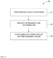
- the invention proposes a method for the reformation of an intermediate circuit capacitor formed from at least one electrolytic capacitor, as illustrated in a highly simplified schematic diagram in Fig. 4 .
- the method 60 in Fig. 4 begins with the step 61, according to which a precharging circuit for the converter is provided, for example, the precharging circuit 29 for the frequency converter 14 in Fig. 1 , which is configured to precharge an intermediate circuit capacitor of the converter, for example, the intermediate circuit capacitor 24, before the converter, for example, after prolonged storage or non-use is connected again to the supply grid 2.
- the precharging circuit comprises a switching device, for example 31, which is arranged on a current path, for example 9, between the supply grid and the intermediate circuit capacitor.
- a precharging circuit already exists in many conventional converter systems and can now be used to fulfill the additional function of the reformation.
- the method 60 in step 61 further comprises a receipt of a request for the reformation of the electrolytic capacitor(s) of the intermediate circuit capacitor of the converter.
- a request can be provided, for example, by an operator, for example, a maintenance technician, after a maintenance measure has been taken or after a replacement of one or a plurality of electrolytic capacitors via a switch or another input interface provided for this purpose.
- such a request signal is, however, provided by the internal control device, for example, the control device 12 of conversion system 4.
- the control device can, based on the system software, the stored parameters and/or the measurement signals, detect conditions that indicate a need for a reformation of the intermediate circuit capacitor, to subsequently start the reformation process automatically, i.e. by self-activation, without intervention by a user.
- control device for example 12, can, for example, detect that the converter was out of operation for a period of time greater than a predetermined first period of time T th1 , so that the intermediate circuit capacitor has received no power.
- the first period of time T th1 can be determined according to a suitable time threshold that is dependent on the particular application and can be determined empirically. In general, T th1 can correspond to one or several hours or one or several days.
- the control device for example 12, additionally or alternatively, can also detect that an electrolytic capacitor forming the intermediate circuit capacitor has been replaced. For example, the maintenance technician can parameterize the converter system accordingly when replacing an electrolytic capacitor, in order to record the replacement. If an entire circuitboard with electrolytic capacitors is replaced, the control device, if necessary, by querying an identification of the circuitboard, can determine that it has been replaced.
- control device for example 12, can, by means of the measuring device, for example 11, monitor a precharging process for precharging the intermediate circuit capacitor, for example 14, by means of the precharging circuit, for example 29, before it is connected to the grid, and use it for detecting a need for the reformation. If it is detected that the precharging process is not completed within a period of time, which exceeds a predetermined second period of time T th2 , it can be seen as an indication that the insulating properties of the electrolytic capacitors have deteriorated and they require reformation.
- the second period of time T th2 can be empirically determined and suitably set depending on the application. It can be in the range of a few minutes up to an hour or several hours.
- the reformation of the intermediate circuit capacitor can be started in step 63 via the precharging circuit, for example 29.
- the switching device, for example 31, of the precharging circuit is switched to a closed state, preferably by a control device, for example 12, or alternatively by an operator to activate the precharging circuit.
- a reformation current from the supply grid, for example 2 can flow through the closed switching device, for example 31, the precharging resistor, for example 32, and the rectifier circuit, for example 33, to the intermediate circuit capacitor, for example 14, in order to reform it via the precharging circuit.
- the precharging circuit in addition to being used for precharging, can also be used for the reformation of the electrolytic capacitors to build up and regenerate the oxide layer again.
- the method according to the invention is simple and requires little or even no intervention on the part of the operator. There is no need to send competent and experienced maintenance personnel with special reformation devices to the location of the converter systems. The expense associated with the reformation is extremely low and the corresponding expenses can be reduced to a minimum. Electrical access to the DC voltage intermediate circuit is not required. In addition, the risks associated with conventional reformation of electrolytic capacitors in converters are eliminated.
- Fig. 5 shows a simplified flowchart, which illustrates the reformation process via the precharging circuit, for example 29 in Fig. 1 , after the activation in step 63 of the method 60 according to Fig. 4 in greater detail.
- the reformation process is started in step 71.
- the precharging circuit for example 29, is activated in step 72 by closing the switching device, for example 31, as described above.
- a monitoring of the voltage level and, if necessary, the voltage rise of the intermediate circuit DC voltage U ZK and, if necessary, the monitoring of the grid voltage U N at the input of the precharging circuit is started.
- step 73 it is checked whether the intermediate circuit DC voltage U ZK has reached a predetermined level. If this is not the case, the reformation via the precharging circuit is continued and the intermediate circuit DC voltage level continues to be monitored.
- the precharging circuit is deactivated in step 74.
- the electrolytic capacitors can, as a result of their leakage current, reduce the charge.
- the leakage current can be monitored based on the quantity of the intermediate circuit DC voltage U ZK to assess the residual current behavior.
- step 75 it is checked whether a predetermined intermediate circuit DC voltage level has been dropped below. If this is not the case, the precharging circuit can continue, at least for predetermined period of time, to be deactivated to allow for further reduction of the intermediate circuit capacitor charge.
- step 75 If the predetermined intermediate circuit DC voltage level has dropped below (yes in step 75), it is verified, in step 76, whether a predetermined period of time has expired for the current voltage level of the reformation voltage. If this is not the case, the precharging circuit is activated again in step 77 and we return to step 73.
- step 78 is started, which changes to the next reformation voltage level.
- the reformation voltage U R which is applied via the precharging circuit, for example 29, to the intermediate circuit, for example 14, is determined by the grid voltage, by the precharging resistor, for example 32, and by the voltage drops in the second current path, for example 9, including the rectifier circuit, for example 33, and the current intermediate circuit voltage U ZK .
- the reformation voltage U R should be within the permissible limits specified by the manufacturer of the electrolytic capacitor type.
- the reformation current should adhere to the manufacturer's specifications. These manufacturer's specifications can be, for example, in the form of a lookup table or similar, for example in storage 44 of the system 4 according to Fig. 1 , or integrated into the software or firmware 43.
- the control device, for example 12 can then, if necessary, access the stored manufacturer's specifications to suitably set the reformation voltage and the reformation current, so that the specified limits are observed.
- a suitable reformation voltage U R can be achieved, for example, by appropriate clocking of the switching device, for example 31, of the precharging circuit, for example 29, so that, on average, the desired reformation voltage U R results.
- Fig. 6 shows a sequence of the average reformation voltage U R over the course of time and exemplary associated duty cycles for the switching device, for example 31.
- a first duty cycle, T 1 /T is selected, at which the switching device, for example 31, is switched on for the period of time T 1 within the period T.
- the duty cycle for the switching device, for example 31 is increased progressively in that the switch-on duration T 2 , T 3 , ... T n is extended within the period T. In this way, the desired reformation voltage U R and the desired reformation current can be suitably set.
- step 78 a voltage level of the average reformation voltage, which is applied to the DC voltage intermediate circuit, for example from the average voltage U R1 , is changed to the next higher average reformation voltage level, for example U R2 (or from U R2 to U R3 , ... from U R(n-1) to U Rn ).
- U R2 or from U R2 to U R3 , ... from U R(n-1) to U Rn .
- step 78 we can proceed with the optional step 79, in which it is verified whether error conditions exist. If, for example, it is determined that the reformation process takes longer than a third period T th3 , which can be specified in such a way that a reformation process surely should be finished within this period of time T th3 , this indicates that one or a plurality of the electrolytic capacitors in the intermediate circuit capacitor are damaged, or that a fault is present in the precharging circuit or in the frequency converter, for example, a short-circuit of the power semiconductor switches. In this case, the reformation process can be aborted in step 80.
- an error message such as a visual or acoustic message
- An error can also be detected if the intermediate circuit voltage U ZK over the intermediate circuit capacitor, for example 14, does not increase sufficiently or does not increase sufficiently quickly during the reformation process. This may indicate strong leakage currents, which can be caused, for example, by damage to one or a plurality of the electrolytic capacitors.
- step 81 it is verified whether the reformation process can be considered to be completed. For example, on the basis of the intermediate circuit DC voltage U ZK or its drop by the deactivated precharging circuit, it can be determined that the leakage current is below a certain maximum permissible limit value and thus the capacitors have been regenerated sufficiently.
- step 81 If, in step 81, it is determined that the reformation process has not yet been completed, we return to step 77 by reactivating the precharging circuit, and then proceed with step 73.
- step 81 If it is determined that the reformation process has been completed (yes in step 81), the reformation process will be completed in step 82.
- the control device for example 12, in Fig. 1 can optionally continue the precharging process, before the converter, for example the frequency converter 14 in Fig. 1 , is connected to the grid, for example 2.
- the precharging process is shortened, or can even be omitted, if the intermediate circuit capacitor has already been charged up to a voltage value that is sufficient for the operation during the reformation process.
- a predetermined average reformation voltage U R can be set via the clocking of the switching device, for example 31, and applied over a fixed period of time to the intermediate circuit capacitor, for example 14, to perform the reformation. On the expiry of the specified period of time, the reformation process is terminated automatically.
- the applied average reformation voltage U R can follow a reformation curve, which can be specified or suggested by the manufacturer of the electrolytic capacitors.
- the reformation curve can differ from the gradual increase of the reformation voltage as illustrated in Figs. 5 and 6 .
- the precharging circuit 29 for precharging the intermediate circuit capacitor 14 in system 1 according to Fig. 1 is illustrated here, the precharging circuit used can differ from the one illustrated.
- the rectifier circuit 33 of the precharging circuit 29 could also be controlled, i.e. could have controllable switching elements.
- the precharging circuit could also be connected differently than illustrated in Fig. 1 , but by simply closing a switching device it should allow the use of a current derived from an AC voltage source or a supply grid for precharging an intermediate circuit capacitor as well as for the reformation of the electrolytic capacitors comprising it.
- Fig. 1 shows a converter system 4 with a frequency converter 14, but it should be understood that the method according to the invention could preferably also be applied to other converter systems, which comprise only a rectifier arrangement or an inverter arrangement with an intermediate circuit, which is formed by at least one electrolytic capacitor.
- a precharging circuit for precharging an intermediate circuit capacitor 24 of a converter 14 formed from at least one electrolytic capacitor using a grid current from a supply grid 2 connected before the converter 14 to the supply grid 2 is also used for the reformation of at least one electrolytic capacitor of the intermediate circuit capacitor 14.
- a method is created for the reformation of an intermediate circuit capacitor 24 of a converter 14 formed from at least one electrolytic capacitor, which is connected to a supply grid 2, using a precharging circuit 29.
- a converter 14 is created for converting an AC grid voltage into a direct voltage or vice versa with a device for the reformation of electrolytic capacitors of an intermediate circuit capacitor 24 of the converter 14 using an integrated precharging circuit 29 of the converter 14.
- existing hardware can be used for the reformation of electrolytic capacitors in a converter, and the expense associated with the reformation can be minimized.
Abstract
Description
- The present invention relates to a method for the reformation of an intermediate circuit capacitor of a converter formed from at least one electrolytic capacitor and an associated converter for converting an AC grid voltage to a direct voltage or vice versa.
- Converters for converting alternating current to direct current and vice versa are used in many applications, for example, for coupling electrical grids with variable-speed drives, for energy exchange between two electrical grids, for photovoltaic and wind power plants and the like. To do this, power converters in different circuit topologies and configurations for different power and voltage ranges are known. In the medium-voltage and high-voltage range, multipoint converters are increasingly used, which have a circuit arrangement with controllable switching elements, preferably power semiconductor switches, which can be clocked at high frequencies to generate a plurality of voltage levels and handle higher voltages than the blocking capability of a single power semiconductor switch permits.
- Some converters on the DC voltage side comprise a so-called DC voltage intermediate circuit with an intermediate circuit capacitor arranged therein. In frequency converters to supply power to drive motors or wind power generators, such an intermediate circuit capacitor is arranged between the grid-side rectifier and the load-side inverter and connected in parallel.
- In many applications, the capacity of the intermediate circuit capacitor is substantial. In the case of some very high intermediate circuit voltages in the range of several hundred volts, series connections and/or parallel connections of capacitors, preferably electrolytic capacitors, are generally used to provide the required dielectric strength and to be able to store large charge quantities. Such series and/or parallel connections of electrolytic capacitors are referred to herein as the "intermediate circuit capacitor" in the same manner as a single capacitor.
- Electrolytic capacitors are polarized capacitors whose anode electrode is made of a metal, in the case of aluminum electrolytic capacitors, for example, aluminum, to which an oxide layer is applied electrochemically as insulating layer, which forms the dielectric medium of the capacitor. The electrolyte is the cathode of the electrolytic capacitor. The quality of the oxide, that changes repeatedly in the course of the electrolytic capacitor production and subsequent use, determines the insulating properties of the dielectric medium. With prolonged storage of electrolytic capacitors in voltage-free condition, especially at elevated temperatures, or due to aging, the oxide degenerates, so that its DC conductivity increases. During recommissioning after non-use, the residual current, which flows as a leakage current through the capacitor, may be relatively high shortly after applying a direct voltage. In applications for converters, a very high residual current can lead to the destruction of the electrolytic capacitors of the intermediate circuit capacitor. To prevent this and minimize the interfering conductivity of the dielectric medium, it is necessary to repeat the forming process under voltage in order to repair the electrolytic capacitors after prolonged non-use and build up the oxide layer again. The repetition of the forming process is referred to herein as reformation or reforming.
- To reform the electrolytic capacitors in converters, it is known to slowly ramp up the intermediate circuit of the converter with, for example, an adjustable DC voltage source to a desired reformation voltage. To do so, a technician must connect the voltage source via a special reformation device directly to the intermediate circuit and, for example, slowly adjust it upward according to the specifications of the manufacturers of the electrolytic capacitors. To this end, the converter module must be disconnected from all possible energy sources, in particular from a supply grid, which may optionally require measures from a control center. Furthermore, the technician must ensure by measuring that the converter is in fact switched off, i.e. is currentless and potential-free at the accessible connections. Furthermore, the technician must ensure that the DC voltage intermediate circuit capacitor is discharged before connecting the reformation device to the DC voltage intermediate circuit. For this purpose, physical or electrical access to the DC voltage intermediate circuit conductors is required. The reformation device must also be connected to an auxiliary voltage source of the converter system or must have its own DC voltage supply.
- The reformation process can only be started when all the above measures have been taken. The reformation requires the use of highly qualified, trained personnel, and is time-consuming, costly and prone to human error. Due to the possibility of human errors, it presents a risk to human health of the maintenance staff and the proper functioning of the system.
- Converters with an intermediate circuit capacitor of high capacitance cannot be connected to the grid without taking special measures, since the switch-on current could be excessively high. Such a switch-on current surge could damage or destroy the converter and the intermediate circuit capacitor. In case of adverse circuit impedances, too high a voltage can arise in the intermediate circuit capacitor, and adverse repercussions of the switch-on current surge on the supplying grid are possible.
- To prevent this, converters, in particular frequency converters, usually comprise a precharging circuit for the intermediate circuit capacitor. A precharging circuit for the converter known from practice essentially comprises a switching device, a precharging resistor and an uncontrolled rectifier, which are arranged in series with each other on a current path between the supply grid and the intermediate circuit capacitor. The rectifier can be an uncontrolled rectifier whose converter valves are diodes connected similar to a Graetz bridge. The contacts on the AC voltage side of the switching device are connected to the supply grid. The output of the rectifier is connected to the DC voltage intermediate circuit. By closing the switching device of the precharging circuit, the intermediate circuit capacitor can be charged up slowly to the desired nominal voltage, whereby the precharging resistor in the current path limits the charging current. As soon as the intermediate circuit capacitor has been charged sufficiently, the switching device of the precharging circuit can be disconnected and the converter connected to the supply grid via a contactor so that the converter-powered intermediate circuit capacitor is now directly on the supplying grid. Then, the normal converter operation can be taken up.
- On this basis, it is a task of the invention to create a method for the reformation of an intermediate circuit capacitor of a converter formed from at least one electrolytic capacitor, which is simple and inexpensive and prevents or overcomes many of the above-mentioned disadvantages and shortcomings of conventional reformation methods for electrolytic capacitors in converters. In particular, it is a task of the invention to create such a reformation method which is less prone to errors and reduces the risk of human error and the associated risks.
- A further task of the invention is to create a converter comprising such an implemented method.
- To solve these and other tasks, a method is created for the reformation of an intermediate circuit capacitor of a converter formed from at least one electrolytic capacitor having the characteristics of
independent claim 1, using a precharging circuit for a converter according toclaim 18 and a converter for converting an AC grid voltage into a direct voltage or vice versa according toclaim 19. Advantageous embodiments of the invention are the subject matter of the dependent claims. - According to a first aspect of the invention, a method is created for the reformation of an intermediate circuit capacitor of a converter formed from at least one electrolytic capacitor, which is connected to a supply grid. The method comprises the provision of a precharging circuit for the converter, which is configured to precharge the intermediate circuit capacitor of the converter using a grid current of the supply grid, before the converter is connected to a supply grid. The precharging circuit comprises a switching device on a current path between the supply grid and the intermediate circuit capacitor. The method further comprises a receipt of a request for the reformation of the intermediate circuit capacitor. The method also comprises the switching of the switching device to a closed state on the receipt of the request for the reformation in order to allow a reformation current to flow from the supply grid through the closed switching device and the current path to the intermediate circuit capacitor in order to reform the intermediate circuit capacitor via the precharging circuit.
- According to the invention, the already existing precharging circuit for the converter, in particular frequency converters, is thus used, if required, to reform the electrolytic capacitor(s) which form the intermediate circuit capacitor of the converter. Existing converters that comprise the precharging circuit can be supplemented by a software module for the reformation of the intermediate circuit capacitor, which otherwise uses the existing hardware to precharge the intermediate circuit capacitor to also achieve a reformation of the same. With new converters, a single such precharging and reformation circuit can serve both purposes. Reformation with simple means can be performed quickly and easily. The need for human operation, in particular the use of qualified personnel, can be significantly reduced or even eliminated, with the advantage that the associated risks to the maintenance staff and/or the system are reduced or even eliminated. Also, the maintenance staff does not have to access the intermediate circuit capacitor lines. Many of the protection measures required for conventional reformation processes for electrolytic capacitors of converters can be omitted.
- A reformation process would have to be initiated depending on the fulfillment of one or more conditions, e.g. when using the intermediate circuit capacitor after exceeding a specified storage period or non-use of the converter device. Other possible criteria for initiating a reformation process, such as a direct or indirect evaluation of the level of the leakage current, can be used in addition or as a sole criterion.
- In one embodiment of the invention, the provision of a precharging circuit can comprise the provision of a precharging circuit that further comprises a precharging resistor, which is connected in series to the switching device on the current path between the supply grid and the intermediate circuit capacitor, wherein, during the reformation, the precharging resistor limits a current flow through the current path to the intermediate circuit capacitor. The precharging resistor can also be used advantageously as a reformation resistor to suitably predetermine the reformation current and the reformation voltage. The precharging and reformation circuit is designed at low cost and comprises only a few cost-efficient components.
- The precharging circuit preferably also comprises a rectifier circuit to convert the AC grid voltage to a direct voltage, wherein the amount of the AC grid voltage, the control factor of the switching device as well as the leakage current of the electrolytic capacitor(s) to be reformed determine the reformation voltage for the capacitors during the reformation. The rectifier circuit is preferably an uncontrolled rectifier circuit, for example, based on a Graetz circuit, which gives a slightly pulsating DC output voltage. A controlled rectifier circuit could also be used, but is more complex and more costly in implementation and in operation.
- In preferred embodiments of the method from among any of those mentioned above, the receipt of a request for the reformation of the intermediate circuit capacitor comprises a receipt of a system-internal request signal triggered by an internal control device that is emitted when the control device detects conditions which are a necessary requirement for a reformation of the intermediate circuit capacitor. Thereupon, the control device can start the reformation process automatically, i.e. is self-activating, without the user's intervention. The internal system software of the converter, in particular the control software, thus notifies when a reformation is necessary and triggers it when necessary.
- The detection of conditions that indicate a need for a reformation of the intermediate circuit capacitor can, in particular, comprise that it is determined when the intermediate circuit capacitor has received no power for a period of time that exceeds a predetermined first period of time. If the intermediate circuit capacitor has not been charged for a longer period of time, for example, because the converter was inactive for a prolonged time, this can indicate the need for a reformation. The predetermined first period of time depends on the respective electrolytic capacitor, and can be in the range of some weeks or months. The duration of the inactive time of the converter can be determined and stored in a data storage associated with the system software, to be used when examining the need for a reformation.
- Alternatively or additionally, the detection of conditions that indicate a need for a reformation of the intermediate circuit capacitor can comprise that it is detected when at least one of the electrolytic capacitors forming the intermediate circuit capacitor has been replaced. An exchange of the electrolytic capacitor can be recognized automatically by the system, for example, by the system software querying a circuit board carrying the electrolytic capacitors. A maintenance technician can also note the exchange of one or a plurality of electrolytic capacitors by setting an appropriate parameter in the database or software of the system of the converter, so that the system software subsequently detects that a reformation is necessary.
- In a further alternative or in addition, the detection of conditions that indicate a need for a reformation of the intermediate circuit capacitor can comprise that it is determined that a precharging process for precharging the intermediate circuit capacitor by means of the precharging circuit is not completed within a period of time, which exceeds a predetermined second period of time. An excessive duration of the precharging process can indicate that the leakage current of the intermediate circuit capacitor is too high, and therefore a reformation is necessary. The second period of time can be determined empirically depending on the electrolyte capacitors and the precharging parameters used.
- In other embodiments of the method according to the invention, the receipt of a request for the reformation of the intermediate circuit capacitor can comprise a receipt of an external request signal triggered by an operator. For example, a maintenance technician can start a reformation process after replacing one or a plurality of electrolytic capacitors or carrying out maintenance or servicing work. The reformation process as such is subsequently performed and controlled by the control device of the converter without further intervention by the operator.
- In the method from among any of those mentioned above, the reformation process can be advantageously controlled taking into account a specification or recommendation provided by the respective manufacturer of the at least one electrolytic capacitor forming the intermediate circuit capacitor. These manufacturer's specifications and recommendations on the reformation current, the reforming times and characteristic curves can preferably be stored in the system software or in an internal database of the converter, which can be accessed by the software or control, similarly to a lookup table, sorted by manufacturer, electrolytic capacitor type or the like, and used for the reformation process. Different manufacturers and electrolytic capacitor types can be taken into account. In simplified embodiments, only the reformation specifications or recommendations of the individual electrolytic capacitor type used in the respective converter are stored.
- To meet the specifications of the manufacturer of electrolytic capacitors, the switching device of the precharging and reformation circuit during the reformation process can be clocked so that, on average, a desired reformation voltage on the intermediate circuit capacitor and/or a desired reformation current on the intermediate circuit capacitor results or result. The switching device can, for example, be switched on and off with pulse-width modulation with a predefined or varying clock ratio to achieve an average reformation voltage or an average reformation current which is less than the maximum permissible reformation voltage or the maximum permissible reformation current according to the manufacturer's specifications. Alternatively, a standard reformation process with a fixed clock ratio of the switching device or with a permanently switched-on switching device can be performed, regardless of the electrolytic capacitor type or manufacturer.
- In a further development of the method mentioned previously, the switching device can be clocked so that an average reformation voltage applied to the intermediate circuit capacitor follows a given reformation curve or characteristic curve. This reformation curve is usually dependent on the capacitor manufacturer and type, the storage time and the storage temperature. The applied average reformation voltage can be increased gradually in preferred embodiments to take into account the increasing regeneration of the oxide layer of the electrolytic capacitor and the increasing charge of the same.
- In a further development of the method mentioned above, the switching device is clocked so that a medium reformation voltage applied to the intermediate circuit capacitor is increased gradually, wherein, between each number of cycle times within one voltage level and/or between successive voltage levels of the medium reformation voltage, the switching device is switched off for a predetermined period of time to interrupt a reformation current to the intermediate circuit capacitor. The reformation process is thus carried out intermittently, with an increasing reformation voltage. Such breaks in the reformation process allow the electrolytic capacitors to discharge slightly, via the leakage current, and can be used to estimate the leakage current and the progress of the reformation.
- If, during the reformation process, the intermediate circuit voltage is detected via the intermediate circuit capacitor and/or the grid voltage of the supply grid, the reformation progress can be monitored or controlled advantageously. The reformation process can then be optimized as required, depending on the actual operating conditions. In principle, the leakage current of the intermediate circuit capacitor could also be measured directly, which is less preferred due to the corresponding expense.
- The reformation process can also be used to detect a defect in the intermediate circuit capacitor, the converter or the precharging circuit. If, for example, it is found that the reformation process takes longer than a predefinable third period of time or the intermediate circuit voltage via the intermediate circuit capacitor is insufficient or does not increase sufficiently fast, this can be that indicate a hardware fault, and the reformation process can be aborted. Subsequently, an error message, for example, an optical or acoustic signal indicator on the converter system, can be output or transmitted to a remote center. In the event of a fault, measures can be taken to prevent the operation of the converter, in particular when connecting the converter to the supply grid.
- Otherwise, if it is determined that the reforming process of the electrolytic capacitor has been completed successfully, the switching device of the precharging circuit can be converted to an open state, in order to effectively disconnect the latter from the supply grid. After that, by closing a line disconnector, the converter can be connected to the supply grid.
- Optionally, after determining a successfully completed reformation process and before connecting the converter to the supply grid, preferably automatically, a precharging process for the intermediate circuit capacitor can be performed. Thereby, the intermediate circuit capacitor can be charged to the required nominal voltage for the operation of the converter. The precharging process can also be triggered by an operator, for example by a maintenance technician.
- In preferred applications of the method according to the invention, the converter is a frequency converter configured to exchange electrical energy between an AC voltage supply grid and an electrical machine. The electrical machine can be operated either as a motor or as a generator. Accordingly, the exchange of the electrical energy can occur either from the grid to the machine or vice versa. In particularly preferred applications, the method is used for a frequency converter which supplies a wind power plant generator.
- Another aspect of the invention provides a use of a precharging circuit for a converter, which is configured to precharge an intermediate circuit capacitor of the converter formed from at least one electrolytic capacitor by using a grid current from a supply grid before the converter is connected to the supply grid for the reformation of at least one electrolytic capacitor of the intermediate circuit capacitor. The embodiments and advantages of using the precharging circuit for the reformation process according to the invention can correspond to the embodiments and advantages of the reformation process according to the invention as described above.
- According to a further aspect of the invention, a modular multilevel converter is provided for converting an AC grid voltage to a direct voltage and/or vice versa. The converter comprises a circuit arrangement with controllable switching elements, preferably power semiconductor switches, a DC voltage intermediate circuit, a precharging circuit and a control device. The DC voltage intermediate circuit is arranged on the DC voltage side of the circuit and connected in parallel with it, wherein the DC voltage intermediate circuit comprises an intermediate circuit capacitor formed by one or a plurality of interconnected electrolytic capacitors. The precharging circuit is configured to precharge the intermediate circuit capacitor of the converter using a grid current of the supply grid, before the converter is connected to the supply grid. The precharging circuit comprises a switching device on a current path between the supply grid and the intermediate circuit capacitor. The control device is used to control the operation of the converter depending on the detected operating conditions, wherein said control device is configured to perform a reformation process as described above. The converter may comprise the further developments and advantages mentioned above in connection with the reformation process.
- A preferred converter is a frequency converter for operating an electrical machine in an electrical supply grid, comprising a rectifier unit and an inverter unit, which are coupled to each other via the DC voltage intermediate circuit with the intermediate circuit capacitor. In particularly preferred embodiments, the frequency converter is preferably configured for use in a wind power plant to supply a wind power plant generator. Such frequency converters may already comprise a precharging circuit, as described above, which can be used advantageously to implement a reformation process for the electrolytic capacitors, which is simple, cost-effective and safe to use for personnel and the system. Existing converter systems can easily be retrofitted with the necessary control software to implement the reformation method. In new frequency converters, a precharging process as well as a reformation process can be implemented advantageously with a single hardware device.
- Further advantageous details of embodiments of the invention result from the subordinate claims, the drawing and the associated description. The invention is described in more detail below with reference to a drawing, which shows exemplary but by no means limiting embodiments of the invention, wherein the same reference signs are used in all figures to indicate the same elements. In detail, the drawings are as follows:
-
Fig. 1 illustrates an exemplary system comprising a converter for coupling an electrical power grid with an electrical machine illustrating an exemplary application of the invention in the form of a simplified block diagram; -
Fig. 2 shows an existing precharging circuit for precharging an intermediate circuit capacitor of the converter used insystem 1 according toFig. 1 , shown in a simplified representation and in greater detail; -
Fig. 3 shows a graphical representation illustrating the storability of an exemplary electrolytic capacitor depending on the storage temperature; -
Fig. 4 is a highly simplified schematic flowchart of a reformation process according to the invention for the reformation of electrolytic capacitors in a converter, for example the one ofFig. 1 in a highly simplified schematic diagram; -
Fig. 5 is a flowchart of a preferred embodiment of a reformation process, which can be performed in the implementation of the reformation process ofFig. 3 , shown in a simplified representation; and -
Fig. 6 is a highly simplified time flowchart illustrating the reformation process ofFig. 4 . -
Fig. 1 shows, in a simplified representation, asystem 1, which is suitable in particular for supplying machines for example, drive motors, generators or the like, but also for other applications for example, medium or high-voltage direct current power distribution systems for electrical energy transmission, isolated grid systems or the like.System 1 here comprises an exemplary three-phaseAC voltage source 2, which can in particular be an electrical power grid or wind power plant, in principle also an alternating current (AC) machine, an AC generator or the like, and which hereinafter is simply referred to as the supply grid orgrid 2. Aconverter system 4, which is connected on one side to aload 6 such as an electrical motor or a generator, is connected to thegrid 2 via atransformer 3. In the preferred application for wind power plants, theload 6 may represent a wind power plant generator and theconverter system 4 may be a frequency converter system, which converts the AC grid voltage of thesupply grid 2, which for example can be in the medium-voltage range of 10-20 kV, and which is lowered by thetransformer 3 to a voltage level of, for example, 400-800 V, into an alternating voltage with a frequency that is suitable to supply a windpower plant generator 6. In other applications, the transformer can also be omitted. Likewise, depending on the application, theconverter system 4 may be configured either for rectification only or for inversion only. - It should further be noted that the illustrated
system 1 is shown as a three-phase system in which the respective phases are not shown separately but only together, as indicated by the slash with the numeral "3" above each of the three-phase lines in thesystem 1, shown by customary notation. - The
converter system 4 is connected to thegrid 2 through amain switching device 7, which is a circuit-breaker device, which makes it possible, if necessary, or in case of errors for example, high overload or short-circuit currents, to galvanically disconnect theconverter system 4 from thegrid 2. - The
converter system 2, in the highly simplified representation of the embodiment shown, comprises substantially a first path or maincurrent path 8, a secondcurrent path 9, a measuringdevice 11 and acontrol device 12. The firstcurrent path 8 extends between thecircuit breaker device 7 and theload 6 and comprises aline disconnector 13, afrequency converter 14 and aninterconnected grid choke 15. Theline disconnector 13 is arranged between themain switching device 7 and thegrid choke 15 to be able to disconnect thefrequency converter 14 from the grid if needed or in case of error, even when themain switching device 7 is closed. While themain switching device 7 can be switched, for example, from a remote control center, theline disconnector 13 is controlled by the converter-internal control device 12, indicated by thecontrol path 16 shown as a dashed arrow. - The
frequency inverter 14 is used to convert the AC input voltage present atinput 17 shown inFig. 1 into an AC output voltage with fitting frequency and amplitude at itsoutput 18 to supply theload 6. Thefrequency converter 14 can be divided modularly or functionally in arectifier unit 19, which converts the AC input voltage into an intermediate circuit DC voltage UZK on a DC voltageintermediate circuit 21, and aninverter unit 22, which converts the intermediate circuit DC voltage UZK into the AC output voltage. Theinverter unit 22 is connected in parallel with therectifier unit 19 to the DC voltageintermediate circuit 21. - As shown in
Fig. 1 , thefrequency converter 14 is a converter that comprises, in the forward direction, switchable power semiconductor devices and backward conductive valves. More precisely, a circuit arrangement ofcontrollable elements 23, commonly power semiconductor switches such as bipolar transistors with insulated gate electrode (IGBTs), as illustrated, is provided in therectifier unit 19 and theinverter unit 22 to perform the respective rectifier or inverter functions. Instead of IGBTs, also MOSFETs, gate turn-off thyristors (GTOs), IGC thyristors (integrated gate-commutated thyristors, IGCTs) and other comparable switchable electronic power devices can be used. The controllability of the power semiconductor switches 23, therectifier unit 19 and theinverter unit 22 inFig. 1 is indicated by thecontrol paths 16 shown as dashed arrows, which point from thecontrol device 12 to theunits - Different arrangements and topologies for the rectifier, inverter and frequency converter circuits are known in the prior art, for example single-phase to multiphase, single-stage to multistage converter configurations, which can be used here and in many applications. Just as an example, reference is made to well-known and here usable multipoint converters in the "neutral point clamped" (NPC) topology, the "neutral point piloted" (NPP) topology or modular multilevel converters (MMC or M2C), which comprise, in every phase branch, a number of submodules, each of which is formed by a half or full bridge circuit or another circuit of controllable power semiconductor switches.
- As further shown in
Fig. 1 , therectifier unit 19 and theinverter unit 22 comprise associatedintermediate circuit capacitors intermediate circuit 21. Theintermediate circuit capacitor 24a is connected at the output of therectifier unit 19 between a positive and a negativeDC voltage line intermediate circuit 21, while theintermediate circuit capacitor 24b of theinverter unit 22 is connected in parallel to theintermediate circuit capacitor 24a at the input of theinverter unit 22 to its circuit arrangement. Theintermediate circuit capacitors intermediate circuit capacitor 24. In particular, for the high voltage levels provided here, eachintermediate circuit capacitor intermediate circuit capacitor 24. - The second
current path 9 runs from aconnection point 28 between themain switching device 7 and theline disconnector 13 of the firstcurrent path 8 to the DC voltageintermediate circuit 21. The secondcurrent path 9 comprises aprecharging circuit 29, which is used to precharge theintermediate circuit capacitor 24 to the required DC voltage level before connecting thefrequency inverter 14 to thegrid 2, to avoid high transient switch-on currents, which could otherwise result in the discharging of theintermediate circuit capacitor 24. - The
precharging circuit 29 comprises aswitching device 31, aprecharging resistor 32 and anuncontrolled rectifier circuit 33, which are connected in series on the secondcurrent path 9. Therectifier circuit 33 is connected on the output side via afirst connection line 34 with the positiveDC voltage line 26 of the DC voltageintermediate circuit 21, and via asecond connection line 36 with the negativeDC voltage line 27. - The
precharging circuit 29 is shown in greater detail inFig. 2 . Theconnection line 37 is shown, which connects theprecharging circuit 29 with theconnection point 28 and further with thegrid 2. Acontactor 38 is arranged in the three-phase connection line 37, which forms the switchingdevice 31 and comprises switchingcontacts 39a-39c to interrupt or close allphase lines 37a-c of theconnection line 37 simultaneously as required. - In the
single phase lines 37a-c of theconnection line 37, theresistors 32a-c are provided, which are inserted between the switchingcontacts 39a-39c of thecontactor 38 andAC voltage connections 41a-c of therectifier circuit 33 and form theprecharging resistor 32 according toFig. 1 . - The
uncontrolled rectifier circuit 33 is designed similar to a Graetz bridge, with diodes D1-D6 as converter valves. In the course of this, a pair of rectifier diodes D1 and D2, D3 and D4 or D5 and D6 is arranged, each in series, between the first and thesecond connection line first connection line 34, while the connection points of the series-connected rectifier diodes D1 and D2, D3 and D4 or D5 and D6 form theAC voltage connections 41a-c. The cathodes of the rectifier diodes D1, D3 and D5 are connected to each other and to thefirst connection line 34, while the anodes of the diodes D2, D4 and D6 are connected to each other and to thesecond connection line 36. The first and thesecond connection line DC voltage line intermediate circuit 21 and to theintermediate circuit capacitor 24, which is shown inFig. 2 as an entire polarized electrolytic capacitor. - Again with reference to
Fig. 1 , the converter system further comprises acontrol device 12, which is provided to appropriately control the operation of theconverter system 4 on the basis of the current operating conditions. For the sake of clarity, the control paths are indicated inFig. 1 with dashedarrows 16 only in a few locations. In particular, thecontrol device 12 appropriately controls the power semiconductor switches 23 of thefrequency converter 14 to create, from the transformed grid voltage UN (hereinafter simply referred to as the grid voltage), a suitable AC output voltage to supply theload 6. The control device comprises suitable hardware, for example, one or a plurality of flexible printed circuitboards with a field-programmable gate array (FPGA), which can comprise the different electronic components, including a central processing unit (CPU). InFig. 1 , the hardware of thecontrol device 12 is collectively referred to as function block with thereference sign 42. - The
control device 12 preferably further comprises software or firmware, which is collectively shown asfunction block 43 inFig. 1 . The software can be executed by the CPU to perform the control functions. - The
control device 12 preferably further comprises a storage, represented asfunction block 44, which is used to store programs and/or data, including parameters for theconverter system 4, data collected during the operation of theconverter system 4, etc. RAM memory, flash memory, hard drives, optical or magnetic storage media suitable for this purpose are well known in the prior art. - Although
Fig. 1 shows different function blocks 42, 43, 44 for the hardware, the software and the storage of thecontrol device 12, it is understood that thecontrol device 12 can be entirely implemented in hardware, software, which can be executed on a microprocessor, microcontroller or the like, or as a combination of the two. Thecontrol device 12 can also be distributed to a plurality of control units, which are arranged in different locations in theconverter system 4, to fulfill various part control functions. A part of thecontrol device 12 of theconverter system 4 can be remote and arranged externally. - The
control device 12 controls theconverter system 4 depending on preconfigured parameters and the current operating conditions. The latter are provided to thecontrol device 12 by the measuringdevice 11, which is configured to detect the current operating conditions and to convert them into appropriate signals for thecontrol device 12. The measuringdevice 11 here illustrates how it comprises a gridvoltage detection device 46 and an intermediate circuitvoltage detection device 47. The gridvoltage detection device 46 detects the transformed mains voltage at the connection point between the first and the secondcurrent path precharging circuit 29. The intermediate circuitvoltage detection device 47 is connected to the positive and negativeDC voltage lines intermediate circuit 21 to detect their potentials and determine the intermediate circuit DC voltage UZK present between them. - Although this is not shown, the measuring device can also detect other operating parameters of the
converter system 4, which can comprise currents and voltage potentials on thecurrent paths frequency converter 14, the output voltage of thefrequency converter 14 as well as other voltages and currents, to the extent that they are required for the monitoring and control of the operation of theconverter system 4. These operating parameters are less relevant to the present invention. - The
system 1 as described above works as follows: - If, after an operational standstill, the
converter system 4 is to be brought back in operation again and theload 6 is supplied by thegrid 2 via thefrequency converter 14, the DC voltageintermediate circuit 21 must first be precharged to the respective nominal voltage. This is accomplished with theprecharging circuit 29. It is assumed that themain switching device 7 is already in its closed position, while theline disconnector 13 is open or will be opened. By closing theswitching device 31, thus actuating thecontactor 38, the secondcurrent path 9 can be connected conductively. A charging current taken from the grid current then flows via theclosed switching device 31, theprecharging resistor 32 and theuncontrolled rectifier circuit 33 to the DC voltageintermediate circuit 21, to precharge theintermediate circuit capacitor 24. In the precharging operation, the chargingresistors 32a-c on thecurrent path 9 limit the charging current to an appropriate maximum level at which theintermediate circuit capacitor 24 is not excessively heated and is not damaged. As soon as theintermediate circuit capacitor 24 has been charged up to a predetermined appropriate value for operation, for example, up to the nominal voltage, thecontactor 38 is actuated again to interrupt the secondcurrent path 9. This completes the precharging process. After subsequent closing of theline disconnector 13, thefrequency converter 14 with theintermediate circuit capacitor 24 is then put on the supplyinggrid 2 directly and can be operated in the usual manner. By appropriate control, such as high-frequency pulse-width-modulated clocking of the power semiconductor switches 23 of thefrequency converter 14, the AC grid voltage can then be converted into the AC output voltage for the supply of theload 6. - As already mentioned, the
intermediate circuit capacitor 14 consists of one or a plurality of series-connected and/or parallel-connected electrolytic capacitors, whose anode electrode is made of a metal, for example, aluminum, on which, by anodic oxidation, also called formation, a uniform but extremely thin electrical insulating metal oxide layer, for example aluminum oxide, is generated as a dielectric medium. An important parameter of electrolytic capacitors is their residual current behavior during recommissioning after storage. The leakage current is known as the residual current through the capacitor, which, shortly after applying a direct voltage, is still relatively high and, after prolonged periods of use, drops to a lower value, known as the operating leakage current. For the evaluation of the residual current behavior, the leakage current value is generally used, which, after five minutes' application of a direct voltage, is still flowing as a leakage current through the capacitor. - The dielectric medium of an electrolytic capacitor, if not used for a prolonged period of time, becomes damaged as a result of the degeneration of oxide, so that its insulating properties worsen. In other words, the DC conductivity of the oxide increases, which can cause an electrolytic capacitor, if not used for a longer period of time, when a direct voltage is applied, to carry an excessive leakage current, or overheat and be destroyed.
-
Fig. 3 illustrates the storability of an electrolytic capacitor of an exemplary selected type on the basis of a relationship between the storage time and storage temperature. It is understood that the time and temperature specifications given here are exemplary and type-specific and may differ from those for other electrolytic capacitor types. However,Fig. 3 shows the general relationship, according to which the insulating properties of an electrolytic capacitor generally worsen with increasing storage time and increasing storage temperature. Anarea 48, which is surrounded by a limitcharacteristic curve 49, identifies the area in which the insulating properties of an electrolytic capacitor are adequate, and its leakage current is within predetermined permissible limits. That is, in this area, the electrolytic capacitor can be put back into operation at nominal values without excessive risk of damage to the electrolytic capacitor. In thearea 51 outside the limitcharacteristic curve 49, the insulating properties of an electrolytic capacitor are no longer adequate or the leakage current is outside of predetermined permissible limits, so that there is a high risk that the electrolytic capacitor could be damaged or destroyed when operation is restarted. - To prevent this, it is necessary to repeat the forming process under direct voltage, in order to repair the electrolytic capacitor after prolonged non-use and to build up the oxide layer again. Such a repetition of the forming process (reformation) must be gentle and happen at a slow rate, otherwise, in case of a greater degeneration of the oxide, a high reformation current can flow, which can also lead to damage to the electrolytic capacitor.
- In applications of converters in which electrolytic capacitors are used for an intermediate circuit capacitor, for example, the
intermediate circuit capacitor 24 of thefrequency converter 14 ofFig. 1 , it is customary to perform a reformation with a special reformation device or a special reformation circuit, which is connected to the intermediate circuit to reform the electrolytic capacitors of the intermediate circuit. For this purpose, a skilled maintenance technician must go to the location of the converter system, remove the converter from the grid with the line disconnector, for example thecircuit breaker 13 inFig. 1 , whereby he may be required to leave a control center to open themain switching device 7 to ensure the reliable galvanic disconnection of theconverter system 4 from thegrid 2. The maintenance technician must also ensure, through measurements at different points in the system, that the lines of thesystem 4 are not energized and conduct no current. He must also ensure that theintermediate circuit capacitor 14 is discharged or will be discharged, in order to prevent any hazards when connecting the special reformation device. Only then can the special reformation device be connected to the DC voltageintermediate circuit 21. If the reformation device does not have its own voltage supply, it must be connected to an appropriate auxiliary voltage supply of thesystem 4, if present. Only then can the reformation process be performed. All this is laborious, time-consuming and increases the maintenance costs. Furthermore, there is the risk that, due to an error by the maintenance technicians during the preparatory protective measures or the reformation process, their health or the functioning of the converter system can be jeopardized. - In order to prevent this, the use of a precharging circuit for the converter according to the invention is proposed, for example, the
precharging circuit 29 in theconverter system 4 according toFig. 1 , for the reformation, if required, of an electrolytic capacitor of the intermediate circuit capacitor, for example, theintermediate circuit capacitor 14 inFig. 1 . In particular, the invention proposes a method for the reformation of an intermediate circuit capacitor formed from at least one electrolytic capacitor, as illustrated in a highly simplified schematic diagram inFig. 4 . - The
method 60 inFig. 4 begins with thestep 61, according to which a precharging circuit for the converter is provided, for example, theprecharging circuit 29 for thefrequency converter 14 inFig. 1 , which is configured to precharge an intermediate circuit capacitor of the converter, for example, theintermediate circuit capacitor 24, before the converter, for example, after prolonged storage or non-use is connected again to thesupply grid 2. The precharging circuit comprises a switching device, for example 31, which is arranged on a current path, for example 9, between the supply grid and the intermediate circuit capacitor. Advantageously, such a precharging circuit already exists in many conventional converter systems and can now be used to fulfill the additional function of the reformation. - The
method 60 instep 61 further comprises a receipt of a request for the reformation of the electrolytic capacitor(s) of the intermediate circuit capacitor of the converter. Such a request can be provided, for example, by an operator, for example, a maintenance technician, after a maintenance measure has been taken or after a replacement of one or a plurality of electrolytic capacitors via a switch or another input interface provided for this purpose. - In preferred embodiments, such a request signal is, however, provided by the internal control device, for example, the
control device 12 ofconversion system 4. For example, the control device can, based on the system software, the stored parameters and/or the measurement signals, detect conditions that indicate a need for a reformation of the intermediate circuit capacitor, to subsequently start the reformation process automatically, i.e. by self-activation, without intervention by a user. - In particular, the control device, for example 12, can, for example, detect that the converter was out of operation for a period of time greater than a predetermined first period of time Tth1, so that the intermediate circuit capacitor has received no power. The first period of time Tth1 can be determined according to a suitable time threshold that is dependent on the particular application and can be determined empirically. In general, Tth1 can correspond to one or several hours or one or several days.
- The control device, for example 12, additionally or alternatively, can also detect that an electrolytic capacitor forming the intermediate circuit capacitor has been replaced. For example, the maintenance technician can parameterize the converter system accordingly when replacing an electrolytic capacitor, in order to record the replacement. If an entire circuitboard with electrolytic capacitors is replaced, the control device, if necessary, by querying an identification of the circuitboard, can determine that it has been replaced.
- In another further development of the invention, the control device, for example 12, can, by means of the measuring device, for example 11, monitor a precharging process for precharging the intermediate circuit capacitor, for example 14, by means of the precharging circuit, for example 29, before it is connected to the grid, and use it for detecting a need for the reformation. If it is detected that the precharging process is not completed within a period of time, which exceeds a predetermined second period of time Tth2, it can be seen as an indication that the insulating properties of the electrolytic capacitors have deteriorated and they require reformation. The second period of time Tth2 can be empirically determined and suitably set depending on the application. It can be in the range of a few minutes up to an hour or several hours.
- Once a request for the reformation of the intermediate circuit capacitor has been received at
step 62, the reformation of the intermediate circuit capacitor, for example 14, can be started instep 63 via the precharging circuit, for example 29. For this purpose, the switching device, for example 31, of the precharging circuit is switched to a closed state, preferably by a control device, for example 12, or alternatively by an operator to activate the precharging circuit. Subsequently, a reformation current from the supply grid, for example 2, can flow through the closed switching device, for example 31, the precharging resistor, for example 32, and the rectifier circuit, for example 33, to the intermediate circuit capacitor, for example 14, in order to reform it via the precharging circuit. Advantageously, the precharging circuit, in addition to being used for precharging, can also be used for the reformation of the electrolytic capacitors to build up and regenerate the oxide layer again. - The method according to the invention is simple and requires little or even no intervention on the part of the operator. There is no need to send competent and experienced maintenance personnel with special reformation devices to the location of the converter systems. The expense associated with the reformation is extremely low and the corresponding expenses can be reduced to a minimum. Electrical access to the DC voltage intermediate circuit is not required. In addition, the risks associated with conventional reformation of electrolytic capacitors in converters are eliminated.
-
Fig. 5 shows a simplified flowchart, which illustrates the reformation process via the precharging circuit, for example 29 inFig. 1 , after the activation instep 63 of themethod 60 according toFig. 4 in greater detail. - The reformation process is started in
step 71. - For this purpose, the precharging circuit, for example 29, is activated in
step 72 by closing the switching device, for example 31, as described above. In addition, a monitoring of the voltage level and, if necessary, the voltage rise of the intermediate circuit DC voltage UZK and, if necessary, the monitoring of the grid voltage UN at the input of the precharging circuit is started. - In
step 73, it is checked whether the intermediate circuit DC voltage UZK has reached a predetermined level. If this is not the case, the reformation via the precharging circuit is continued and the intermediate circuit DC voltage level continues to be monitored. - As soon as the predetermined intermediate circuit DC voltage level has been reached (yes in step 73), the precharging circuit is deactivated in
step 74. In this time, which can be set at 5 minutes or more, the electrolytic capacitors can, as a result of their leakage current, reduce the charge. The leakage current can be monitored based on the quantity of the intermediate circuit DC voltage UZK to assess the residual current behavior. - In
step 75, it is checked whether a predetermined intermediate circuit DC voltage level has been dropped below. If this is not the case, the precharging circuit can continue, at least for predetermined period of time, to be deactivated to allow for further reduction of the intermediate circuit capacitor charge. - If the predetermined intermediate circuit DC voltage level has dropped below (yes in step 75), it is verified, in
step 76, whether a predetermined period of time has expired for the current voltage level of the reformation voltage. If this is not the case, the precharging circuit is activated again instep 77 and we return to step 73. - Otherwise (yes in step 76),
step 78 is started, which changes to the next reformation voltage level. - The reformation voltage UR, which is applied via the precharging circuit, for example 29, to the intermediate circuit, for example 14, is determined by the grid voltage, by the precharging resistor, for example 32, and by the voltage drops in the second current path, for example 9, including the rectifier circuit, for example 33, and the current intermediate circuit voltage UZK. The reformation voltage UR should be within the permissible limits specified by the manufacturer of the electrolytic capacitor type. Likewise, the reformation current should adhere to the manufacturer's specifications. These manufacturer's specifications can be, for example, in the form of a lookup table or similar, for example in
storage 44 of thesystem 4 according toFig. 1 , or integrated into the software orfirmware 43. The control device, for example 12, can then, if necessary, access the stored manufacturer's specifications to suitably set the reformation voltage and the reformation current, so that the specified limits are observed. - A suitable reformation voltage UR can be achieved, for example, by appropriate clocking of the switching device, for example 31, of the precharging circuit, for example 29, so that, on average, the desired reformation voltage UR results. This is exemplified in
Fig. 6 , which shows a sequence of the average reformation voltage UR over the course of time and exemplary associated duty cycles for the switching device, for example 31. - As shown in
Fig. 6 , if a first average reformation voltage levelU R1 is desired, a first duty cycle, T1/T is selected, at which the switching device, for example 31, is switched on for the period of time T1 within the period T. If a higher average reformation voltage levelU R2,U R3, ...U Rn is desired, the duty cycle for the switching device, for example 31, is increased progressively in that the switch-on duration T2, T3, ... Tn is extended within the period T. In this way, the desired reformation voltageU R and the desired reformation current can be suitably set. - Returning to
Fig. 5 , instep 78, a voltage level of the average reformation voltage, which is applied to the DC voltage intermediate circuit, for example from the average voltageU R1, is changed to the next higher average reformation voltage level, for exampleU R2 (or fromU R2 toU R3, ... from UR(n-1) toU Rn). This takes into account that, during the reformation, the intermediate circuit capacitor is increasingly repaired and the intermediate circuit becomes increasingly charged, so that an increasingly high reformation voltage is necessary and suitable. - After
step 78, we can proceed with theoptional step 79, in which it is verified whether error conditions exist. If, for example, it is determined that the reformation process takes longer than a third period Tth3, which can be specified in such a way that a reformation process surely should be finished within this period of time Tth3, this indicates that one or a plurality of the electrolytic capacitors in the intermediate circuit capacitor are damaged, or that a fault is present in the precharging circuit or in the frequency converter, for example, a short-circuit of the power semiconductor switches. In this case, the reformation process can be aborted instep 80. Preferably, an error message, such as a visual or acoustic message, can be output automatically on a display, not further shown here, of the converter system or transmitted as an error message via a wireless, wired or telephone network to a remote control center. An error can also be detected if the intermediate circuit voltage UZK over the intermediate circuit capacitor, for example 14, does not increase sufficiently or does not increase sufficiently quickly during the reformation process. This may indicate strong leakage currents, which can be caused, for example, by damage to one or a plurality of the electrolytic capacitors. - If no error conditions are detected (no in step 79), in
step 81 it is verified whether the reformation process can be considered to be completed. For example, on the basis of the intermediate circuit DC voltage UZK or its drop by the deactivated precharging circuit, it can be determined that the leakage current is below a certain maximum permissible limit value and thus the capacitors have been regenerated sufficiently. - If, in
step 81, it is determined that the reformation process has not yet been completed, we return to step 77 by reactivating the precharging circuit, and then proceed withstep 73. - If it is determined that the reformation process has been completed (yes in step 81), the reformation process will be completed in
step 82. - If the
reformation process 70 has been completed, then the control device, for example 12, inFig. 1 can optionally continue the precharging process, before the converter, for example thefrequency converter 14 inFig. 1 , is connected to the grid, for example 2. Advantageously, the precharging process is shortened, or can even be omitted, if the intermediate circuit capacitor has already been charged up to a voltage value that is sufficient for the operation during the reformation process. - In the context of the invention, numerous modifications are possible to the method and converter according to the invention. Whereas the illustrated reformation process in
Fig. 5 is preferred, depending on the application and requirements, it can also be performed with modifications. In a particularly simple embodiment, for example, a predetermined average reformation voltageU R can be set via the clocking of the switching device, for example 31, and applied over a fixed period of time to the intermediate circuit capacitor, for example 14, to perform the reformation. On the expiry of the specified period of time, the reformation process is terminated automatically. - In another embodiment, the applied average reformation voltage
U R can follow a reformation curve, which can be specified or suggested by the manufacturer of the electrolytic capacitors. The reformation curve can differ from the gradual increase of the reformation voltage as illustrated inFigs. 5 and6 . - Although a
certain precharging circuit 29 for precharging theintermediate circuit capacitor 14 insystem 1 according toFig. 1 is illustrated here, the precharging circuit used can differ from the one illustrated. For example, therectifier circuit 33 of theprecharging circuit 29 could also be controlled, i.e. could have controllable switching elements. The precharging circuit could also be connected differently than illustrated inFig. 1 , but by simply closing a switching device it should allow the use of a current derived from an AC voltage source or a supply grid for precharging an intermediate circuit capacitor as well as for the reformation of the electrolytic capacitors comprising it. - Furthermore,
Fig. 1 shows aconverter system 4 with afrequency converter 14, but it should be understood that the method according to the invention could preferably also be applied to other converter systems, which comprise only a rectifier arrangement or an inverter arrangement with an intermediate circuit, which is formed by at least one electrolytic capacitor. - According to one aspect of the invention, a precharging circuit for precharging an
intermediate circuit capacitor 24 of aconverter 14 formed from at least one electrolytic capacitor using a grid current from asupply grid 2 connected before theconverter 14 to thesupply grid 2 is also used for the reformation of at least one electrolytic capacitor of theintermediate circuit capacitor 14. According to a further aspect of the invention, a method is created for the reformation of anintermediate circuit capacitor 24 of aconverter 14 formed from at least one electrolytic capacitor, which is connected to asupply grid 2, using aprecharging circuit 29. According to yet another aspect of the invention, aconverter 14 is created for converting an AC grid voltage into a direct voltage or vice versa with a device for the reformation of electrolytic capacitors of anintermediate circuit capacitor 24 of theconverter 14 using anintegrated precharging circuit 29 of theconverter 14. Advantageously, existing hardware can be used for the reformation of electrolytic capacitors in a converter, and the expense associated with the reformation can be minimized.
Claims (20)
- A method for reforming an intermediate circuit capacitor (24) of a converter (14), the capacitor comprising at least one electrolytic capacitor which is connected to an electric grid (2), wherein the method comprises:providing (61) a precharging circuit (29) for the converter (14),the precharging circuit (29) configured to precharge the intermediate circuit capacitor (24) using a grid current of the grid (2) prior to the connection of the converter (10) to the grid (2), wherein said precharging circuit (29) comprises a switching device (31) in a current path (9) between the grid (2) and the intermediate circuit capacitor (24);receiving (62) a request to reform the intermediate circuit capacitor (24); andswitching the switching device (31) to a closed state to allow a reformation current to flow from the grid (2) through the closed switching device (31) and the current path (9) to the intermediate circuit capacitor (24) in order to reform it via the precharging circuit (29).
- A method according to claim 1, wherein providing the precharging circuit (29) comprises providing a precharging circuit (29) that further comprises a precharging resistor (32) connected in series with the switching device (31) in the current path (9) between the grid (2) and the intermediate circuit capacitor (24), wherein the precharging resistor (32), is configured to limit the current flow through the current path (9) to the intermediate circuit capacitor (24) during reforming of the intermediate circuit capacitor (24).
- A method according to claim 1 or 2, wherein the precharging circuit (29) further comprises a non-controlled rectifier circuit (33) configured to convert the AC grid voltage of the grid (2) to a direct voltage, wherein, during reforming of the intermediate circuit capacitor (24), a reformation voltage (UR) for the intermediate circuit capacitor (24) is determined by the AC grid voltage level, a control factor of the switching device (31) and the leakage current of the intermediate circuit capacitor (24).
- A method according to any of the preceding claims, further comprising transmitting by a control device (12) a request to reform the intermediate circuit capacitor (24) and starting the reformation process automatically.
- A method according to claim 4, wherein detecting the need for reforming the intermediate circuit capacitor (24) comprises detecting that the intermediate circuit capacitor (24) has received no power for a period of time exceeding a predetermined first period of time (Tth1).
- A method according to claim 4, wherein detecting the need for reforming the intermediate circuit capacitor (24) comprises detecting that at least one of the electrolytic capacitors forming the intermediate circuit capacitor (24) has been replaced.
- A method according to claim 4, wherein detecting the need for reforming the intermediate circuit capacitor (24) comprises detecting that a precharging process for precharging the intermediate circuit capacitor (24) by means of the precharging circuit (29) is not completed within a period of time that exceeds a predetermined second period of time (Tth2).
- A method according to any one of the preceding claims, wherein receiving a request to reform the intermediate circuit capacitor (24) comprises a receiving an external request signal triggered by an operator.
- A method according to any of the preceding claims, further comprising controlling reforming of the intermediate circuit capacitor (24) by taking into account a specification or recommendation provided by a manufacturer of the at least one electrolytic capacitor of the intermediate circuit capacitor (24).
- A method according to any of the preceding claims, further comprising controlling switching of the switching device (31) so as to achieve a desired reformation voltage (UR) on the intermediate circuit capacitor (24) and/or a desired reformation current to the intermediate circuit capacitor (24)
- A method according to any preceding claim, further comprising controlling switching of the switching device (31) so that an average reformation voltage (UR) applied to the intermediate circuit capacitor (24) follows a specified curve.
- A method according to claim 11, wherein, between each number of cycle times within one voltage level and/or between successive voltage levels of the average reformation voltage (UR), the switching device (31) is switched off for a predetermined period of time to interrupt a reformation current to the intermediate circuit capacitor (24).
- A method according to any of the preceding claims, further comprising detecting the intermediate circuit voltage (UZK) via the intermediate circuit capacitor (24) and/or the grid voltage (UN) of the grid (2) to monitor and control the progress of the reforming process.
- A method according to any of the preceding claims, further comprising at least one of:detecting if the time taken to reform the intermediate circuit capacitor (24) exceeds a predefined third period of time (Tth3);detecting if the intermediate circuit voltage (UZK) is less than a predetermined value; anddetecting that the rate of increase of the intermediate circuit voltage (UZK) is less than a predetermined value;and if so, aborting reforming of the intermediate circuit capacitor and generating an error message.
- A method according to any of the preceding claims, further comprising determining that reforming of the intermediate circuit capacitor has completed and switching the switching device (31) to an open state.
- A method according to any claim 15, wherein, after determining a successfully completed reformation process, precharging the intermediate circuit capacitor (24) prior to connection of the converter (10) to the grid (2).
- A method according to any of the preceding claims, wherein the converter is a frequency converter (14) configured to exchange electrical energy between an AC voltage grid (2) and an electrical machine (6).
- Use of a precharging circuit (29) to precharge an intermediate circuit capacitor (24) of a converter (14), the capacitor (24) comprising at least one electrolytic capacitor connected to an electric grid (2) wherein the precharging circuit (29) configured to precharge the intermediate circuit capacitor (24) using a grid current of the grid (2) prior to the connection of the converter (10) to the grid (2).,
- A converter for converting a AC grid voltage to a direct voltage or a direct voltage to an a AC grid voltage, comprising:a circuit comprising controllable switching elements (23);a DC voltage intermediate circuit (21) arranged on the DC voltage side of the circuit and connected in parallel with it, wherein the DC voltage intermediate circuit (21) comprises an intermediate circuit capacitor (24) formed by at least one electrolytic capacitor;a precharging circuit (29) configured configured to precharge the intermediate circuit capacitor (24) using a grid current of the grid (2) prior to the connection of the converter (10) to the grid (2), wherein said precharging circuit (29) comprises a switching device (31) in a current path (9) between the grid (2) and the intermediate circuit capacitor (24); anda control device (12) for controlling the operation of the converter (14) depending on the operating conditions, wherein said control device (12) is configured to perform a method according to any of claims 1 to 17.
- A converter according to claim 19, wherein the converter comprises a frequency converter (14) for operating an electrical machine (6) on an electrical AC voltage grid (2), the converter further comprising a rectifier unit (19) and an inverter unit (22) coupled to each other via the DC voltage intermediate circuit (21), wherein the frequency converter (14) is configured to supply a wind power plant generator.
Applications Claiming Priority (1)
| Application Number | Priority Date | Filing Date | Title |
|---|---|---|---|
| DE102016117379.7A DE102016117379A1 (en) | 2016-09-15 | 2016-09-15 | Process for reforming an electrolytic capacitor in a power converter and power converter with this |
Publications (1)
| Publication Number | Publication Date |
|---|---|
| EP3297148A1 true EP3297148A1 (en) | 2018-03-21 |
Family
ID=59846482
Family Applications (1)
| Application Number | Title | Priority Date | Filing Date |
|---|---|---|---|
| EP17190356.0A Withdrawn EP3297148A1 (en) | 2016-09-15 | 2017-09-11 | Method for the reformation of an electrolytic capacitor in a converter and converter with such |
Country Status (3)
| Country | Link |
|---|---|
| US (1) | US10498152B2 (en) |
| EP (1) | EP3297148A1 (en) |
| DE (1) | DE102016117379A1 (en) |
Families Citing this family (4)
| Publication number | Priority date | Publication date | Assignee | Title |
|---|---|---|---|---|
| DE102020130765A1 (en) | 2020-11-20 | 2022-05-25 | Dr. Ing. H.C. F. Porsche Aktiengesellschaft | Method and device for formation |
| EP4033648A1 (en) | 2021-01-25 | 2022-07-27 | ABB Schweiz AG | Ups device with passive balancing |
| CN114374238A (en) * | 2021-03-31 | 2022-04-19 | 华为数字能源技术有限公司 | Electrolytic capacitor self-repairing method and device, electronic equipment and storage medium |
| US20230260719A1 (en) * | 2022-02-11 | 2023-08-17 | Carrier Corporation | Low cost reforming circuitry for electrolytic capacitors in variable frequency drive applications |
Citations (2)
| Publication number | Priority date | Publication date | Assignee | Title |
|---|---|---|---|---|
| EP1494343A2 (en) * | 2003-07-04 | 2005-01-05 | ABB Oy | Frequency converter and drive for electric motor |
| US20120099347A1 (en) * | 2010-10-21 | 2012-04-26 | Abb Oy | Frequency converter assembly |
Family Cites Families (8)
| Publication number | Priority date | Publication date | Assignee | Title |
|---|---|---|---|---|
| DE102004036211A1 (en) * | 2004-07-26 | 2006-03-23 | Siemens Ag | Electrolytic capacitor deterioration determining method, involves calculating delay time based on measured voltages, and comparing delay time with predetermined delay time, where difference in times is measure for deterioration of capacitor |
| US20070049981A1 (en) * | 2005-08-23 | 2007-03-01 | Rorvick Anthony W | Capacitor reformation method and device configured to perform the capacitor reformation method |
| US7929323B2 (en) * | 2008-09-26 | 2011-04-19 | Rockwell Automation Technologies, Inc. | Method and apparatus for pre-charging power converters and diagnosing pre-charge faults |
| DE102008060546B3 (en) * | 2008-12-04 | 2010-04-01 | Imp Gmbh | Process for reforming electrolytic capacitors |
| US9184685B2 (en) * | 2010-10-28 | 2015-11-10 | Vestas Wind Systems A/S | Wind turbine generator |
| EP2523334A1 (en) * | 2011-05-11 | 2012-11-14 | Siemens Aktiengesellschaft | Frequency inverter and method for operating same |
| US9156343B2 (en) * | 2011-12-27 | 2015-10-13 | GM Global Technology Operations LLC | Electrolytic capacitor reformation systems and methods |
| DE102012222928A1 (en) * | 2012-12-12 | 2014-06-12 | Robert Bosch Gmbh | Precharge circuit for charging a DC link capacitor |
-
2016
- 2016-09-15 DE DE102016117379.7A patent/DE102016117379A1/en not_active Ceased
-
2017
- 2017-09-11 EP EP17190356.0A patent/EP3297148A1/en not_active Withdrawn
- 2017-09-15 US US15/705,336 patent/US10498152B2/en active Active
Patent Citations (2)
| Publication number | Priority date | Publication date | Assignee | Title |
|---|---|---|---|---|
| EP1494343A2 (en) * | 2003-07-04 | 2005-01-05 | ABB Oy | Frequency converter and drive for electric motor |
| US20120099347A1 (en) * | 2010-10-21 | 2012-04-26 | Abb Oy | Frequency converter assembly |
Non-Patent Citations (1)
| Title |
|---|
| 00522808_G DOC ET AL: "ABB Drives CAPACITOR REFORMING Inspection Instruction 3AFE 6873 5190 APPROVED/DAVIDSAINEN JANNE GUIDE FOR CAPACITOR REFORMING IN", 5 May 2010 (2010-05-05), XP055392954, Retrieved from the Internet <URL:https://library.e.abb.com/public/cf2c9be9fc666ebbc1257729002bd7be/Guide_for_capacitor_reforming_Rev_G.pdf?x-sign=ui3uvjB/LCUopm+GK1YBgU9Je57ZPQ9HaFmI0Q91exkTG2ZqnclPSPOPD70Xbd9n> [retrieved on 20170721] * |
Also Published As
| Publication number | Publication date |
|---|---|
| DE102016117379A1 (en) | 2018-03-15 |
| US10498152B2 (en) | 2019-12-03 |
| US20180076642A1 (en) | 2018-03-15 |
Similar Documents
| Publication | Publication Date | Title |
|---|---|---|
| US10498152B2 (en) | Method for the reformation of an electrolytic capacitor in a converter and converter with such | |
| JP6730515B2 (en) | Power converter | |
| US20170302189A1 (en) | Device for temporarily taking over electrical current from an energy transfer or distribution device, when needed | |
| CN102474172B (en) | Method for discharging intermediate circuit capacitor of intermediate voltage circuit converter | |
| US8896149B2 (en) | Electric power converting system | |
| CN107306047A (en) | Equipment for controlling charging system for motor-driven vehicle | |
| CN102498650A (en) | Starting up a dc/dc converter having a high-frequency transformer | |
| KR102349306B1 (en) | System for testing sub-module of modular multilevel converter | |
| US20120274288A1 (en) | Providing in rush current tolerance to an electronic device | |
| CN111398772A (en) | Circuit, method and device for converter valve overcurrent turn-off test | |
| JP6662551B2 (en) | Power converter | |
| JP2017216809A (en) | Power inversion apparatus | |
| US20220311354A1 (en) | Intelligent discharge control for modular multilevel converter | |
| JP2014128165A (en) | Insulation determination system | |
| CN103048596B (en) | End-to-end direct-current voltage withstand testing device and method of MMC (modular multilevel converter) valve | |
| JP5748610B2 (en) | Charger | |
| US20220214406A1 (en) | Electrical System Testing Processes | |
| EP3391543A1 (en) | Voltage balancing of voltage source converters | |
| JP2014117070A (en) | Charger | |
| CN210201543U (en) | Charging circuit for improving reliability and photovoltaic air conditioning equipment | |
| Nuutinen et al. | LVDC customer-end inverter operation in short circuit | |
| JP6444204B2 (en) | Power converter | |
| US20230141552A1 (en) | Semiconductor testing device, semiconductor testing method, and manufacturing method for semiconductor device | |
| US20210359621A1 (en) | Drive system with common dc bus | |
| JP2016220431A (en) | Power conversion device |
Legal Events
| Date | Code | Title | Description |
|---|---|---|---|
| PUAI | Public reference made under article 153(3) epc to a published international application that has entered the european phase |
Free format text: ORIGINAL CODE: 0009012 |
|
| STAA | Information on the status of an ep patent application or granted ep patent |
Free format text: STATUS: THE APPLICATION HAS BEEN PUBLISHED |
|
| AK | Designated contracting states |
Kind code of ref document: A1 Designated state(s): AL AT BE BG CH CY CZ DE DK EE ES FI FR GB GR HR HU IE IS IT LI LT LU LV MC MK MT NL NO PL PT RO RS SE SI SK SM TR |
|
| AX | Request for extension of the european patent |
Extension state: BA ME |
|
| STAA | Information on the status of an ep patent application or granted ep patent |
Free format text: STATUS: REQUEST FOR EXAMINATION WAS MADE |
|
| 17P | Request for examination filed |
Effective date: 20180921 |
|
| RBV | Designated contracting states (corrected) |
Designated state(s): AL AT BE BG CH CY CZ DE DK EE ES FI FR GB GR HR HU IE IS IT LI LT LU LV MC MK MT NL NO PL PT RO RS SE SI SK SM TR |
|
| STAA | Information on the status of an ep patent application or granted ep patent |
Free format text: STATUS: EXAMINATION IS IN PROGRESS |
|
| STAA | Information on the status of an ep patent application or granted ep patent |
Free format text: STATUS: EXAMINATION IS IN PROGRESS |
|
| 17Q | First examination report despatched |
Effective date: 20201211 |
|
| STAA | Information on the status of an ep patent application or granted ep patent |
Free format text: STATUS: THE APPLICATION IS DEEMED TO BE WITHDRAWN |
|
| 18D | Application deemed to be withdrawn |
Effective date: 20210422 |