EP3297071A1 - High pressure type hydride secondary battery - Google Patents
High pressure type hydride secondary battery Download PDFInfo
- Publication number
- EP3297071A1 EP3297071A1 EP17190371.9A EP17190371A EP3297071A1 EP 3297071 A1 EP3297071 A1 EP 3297071A1 EP 17190371 A EP17190371 A EP 17190371A EP 3297071 A1 EP3297071 A1 EP 3297071A1
- Authority
- EP
- European Patent Office
- Prior art keywords
- hydrogen
- mmni
- pressure
- less
- absorbing alloy
- Prior art date
- Legal status (The legal status is an assumption and is not a legal conclusion. Google has not performed a legal analysis and makes no representation as to the accuracy of the status listed.)
- Granted
Links
Images


Classifications
-
- H—ELECTRICITY
- H01—ELECTRIC ELEMENTS
- H01M—PROCESSES OR MEANS, e.g. BATTERIES, FOR THE DIRECT CONVERSION OF CHEMICAL ENERGY INTO ELECTRICAL ENERGY
- H01M10/00—Secondary cells; Manufacture thereof
- H01M10/34—Gastight accumulators
- H01M10/345—Gastight metal hydride accumulators
-
- H—ELECTRICITY
- H01—ELECTRIC ELEMENTS
- H01M—PROCESSES OR MEANS, e.g. BATTERIES, FOR THE DIRECT CONVERSION OF CHEMICAL ENERGY INTO ELECTRICAL ENERGY
- H01M10/00—Secondary cells; Manufacture thereof
- H01M10/42—Methods or arrangements for servicing or maintenance of secondary cells or secondary half-cells
- H01M10/52—Removing gases inside the secondary cell, e.g. by absorption
-
- B—PERFORMING OPERATIONS; TRANSPORTING
- B22—CASTING; POWDER METALLURGY
- B22F—WORKING METALLIC POWDER; MANUFACTURE OF ARTICLES FROM METALLIC POWDER; MAKING METALLIC POWDER; APPARATUS OR DEVICES SPECIALLY ADAPTED FOR METALLIC POWDER
- B22F9/00—Making metallic powder or suspensions thereof
- B22F9/02—Making metallic powder or suspensions thereof using physical processes
- B22F9/04—Making metallic powder or suspensions thereof using physical processes starting from solid material, e.g. by crushing, grinding or milling
-
- C—CHEMISTRY; METALLURGY
- C01—INORGANIC CHEMISTRY
- C01B—NON-METALLIC ELEMENTS; COMPOUNDS THEREOF; METALLOIDS OR COMPOUNDS THEREOF NOT COVERED BY SUBCLASS C01C
- C01B3/00—Hydrogen; Gaseous mixtures containing hydrogen; Separation of hydrogen from mixtures containing it; Purification of hydrogen; Reversible storage of hydrogen
- C01B3/0005—Reversible storage of hydrogen, e.g. by hydrogen getters or electrodes
- C01B3/001—Reversible storage of hydrogen, e.g. by hydrogen getters or electrodes characterised by the uptaking media; Treatment thereof
- C01B3/0018—Inorganic elements or compounds, e.g. oxides, nitrides, borohydrides or zeolites; Solutions thereof
- C01B3/0031—Intermetallic compounds; Metal alloys
-
- C—CHEMISTRY; METALLURGY
- C01—INORGANIC CHEMISTRY
- C01B—NON-METALLIC ELEMENTS; COMPOUNDS THEREOF; METALLOIDS OR COMPOUNDS THEREOF NOT COVERED BY SUBCLASS C01C
- C01B3/00—Hydrogen; Gaseous mixtures containing hydrogen; Separation of hydrogen from mixtures containing it; Purification of hydrogen; Reversible storage of hydrogen
- C01B3/0005—Reversible storage of hydrogen, e.g. by hydrogen getters or electrodes
- C01B3/001—Reversible storage of hydrogen, e.g. by hydrogen getters or electrodes characterised by the uptaking media; Treatment thereof
- C01B3/0018—Inorganic elements or compounds, e.g. oxides, nitrides, borohydrides or zeolites; Solutions thereof
- C01B3/0031—Intermetallic compounds; Metal alloys
- C01B3/0047—Intermetallic compounds; Metal alloys containing a rare earth metal
- C01B3/0057—Intermetallic compounds; Metal alloys containing a rare earth metal and nickel
-
- C—CHEMISTRY; METALLURGY
- C22—METALLURGY; FERROUS OR NON-FERROUS ALLOYS; TREATMENT OF ALLOYS OR NON-FERROUS METALS
- C22C—ALLOYS
- C22C19/00—Alloys based on nickel or cobalt
- C22C19/007—Alloys based on nickel or cobalt with a light metal (alkali metal Li, Na, K, Rb, Cs; earth alkali metal Be, Mg, Ca, Sr, Ba, Al Ga, Ge, Ti) or B, Si, Zr, Hf, Sc, Y, lanthanides, actinides, as the next major constituent
-
- C—CHEMISTRY; METALLURGY
- C22—METALLURGY; FERROUS OR NON-FERROUS ALLOYS; TREATMENT OF ALLOYS OR NON-FERROUS METALS
- C22C—ALLOYS
- C22C19/00—Alloys based on nickel or cobalt
- C22C19/03—Alloys based on nickel or cobalt based on nickel
-
- C—CHEMISTRY; METALLURGY
- C22—METALLURGY; FERROUS OR NON-FERROUS ALLOYS; TREATMENT OF ALLOYS OR NON-FERROUS METALS
- C22C—ALLOYS
- C22C19/00—Alloys based on nickel or cobalt
- C22C19/03—Alloys based on nickel or cobalt based on nickel
- C22C19/05—Alloys based on nickel or cobalt based on nickel with chromium
-
- H—ELECTRICITY
- H01—ELECTRIC ELEMENTS
- H01M—PROCESSES OR MEANS, e.g. BATTERIES, FOR THE DIRECT CONVERSION OF CHEMICAL ENERGY INTO ELECTRICAL ENERGY
- H01M10/00—Secondary cells; Manufacture thereof
- H01M10/24—Alkaline accumulators
- H01M10/28—Construction or manufacture
- H01M10/288—Processes for forming or storing electrodes in the battery container
-
- H—ELECTRICITY
- H01—ELECTRIC ELEMENTS
- H01M—PROCESSES OR MEANS, e.g. BATTERIES, FOR THE DIRECT CONVERSION OF CHEMICAL ENERGY INTO ELECTRICAL ENERGY
- H01M10/00—Secondary cells; Manufacture thereof
- H01M10/24—Alkaline accumulators
- H01M10/30—Nickel accumulators
-
- H—ELECTRICITY
- H01—ELECTRIC ELEMENTS
- H01M—PROCESSES OR MEANS, e.g. BATTERIES, FOR THE DIRECT CONVERSION OF CHEMICAL ENERGY INTO ELECTRICAL ENERGY
- H01M4/00—Electrodes
- H01M4/02—Electrodes composed of, or comprising, active material
- H01M4/24—Electrodes for alkaline accumulators
- H01M4/242—Hydrogen storage electrodes
-
- H—ELECTRICITY
- H01—ELECTRIC ELEMENTS
- H01M—PROCESSES OR MEANS, e.g. BATTERIES, FOR THE DIRECT CONVERSION OF CHEMICAL ENERGY INTO ELECTRICAL ENERGY
- H01M4/00—Electrodes
- H01M4/02—Electrodes composed of, or comprising, active material
- H01M4/24—Electrodes for alkaline accumulators
- H01M4/32—Nickel oxide or hydroxide electrodes
-
- H—ELECTRICITY
- H01—ELECTRIC ELEMENTS
- H01M—PROCESSES OR MEANS, e.g. BATTERIES, FOR THE DIRECT CONVERSION OF CHEMICAL ENERGY INTO ELECTRICAL ENERGY
- H01M4/00—Electrodes
- H01M4/02—Electrodes composed of, or comprising, active material
- H01M4/36—Selection of substances as active materials, active masses, active liquids
- H01M4/38—Selection of substances as active materials, active masses, active liquids of elements or alloys
- H01M4/383—Hydrogen absorbing alloys
-
- H—ELECTRICITY
- H01—ELECTRIC ELEMENTS
- H01M—PROCESSES OR MEANS, e.g. BATTERIES, FOR THE DIRECT CONVERSION OF CHEMICAL ENERGY INTO ELECTRICAL ENERGY
- H01M4/00—Electrodes
- H01M4/02—Electrodes composed of, or comprising, active material
- H01M4/36—Selection of substances as active materials, active masses, active liquids
- H01M4/38—Selection of substances as active materials, active masses, active liquids of elements or alloys
- H01M4/383—Hydrogen absorbing alloys
- H01M4/385—Hydrogen absorbing alloys of the type LaNi5
-
- H—ELECTRICITY
- H01—ELECTRIC ELEMENTS
- H01M—PROCESSES OR MEANS, e.g. BATTERIES, FOR THE DIRECT CONVERSION OF CHEMICAL ENERGY INTO ELECTRICAL ENERGY
- H01M4/00—Electrodes
- H01M4/02—Electrodes composed of, or comprising, active material
- H01M4/36—Selection of substances as active materials, active masses, active liquids
- H01M4/48—Selection of substances as active materials, active masses, active liquids of inorganic oxides or hydroxides
- H01M4/52—Selection of substances as active materials, active masses, active liquids of inorganic oxides or hydroxides of nickel, cobalt or iron
-
- B—PERFORMING OPERATIONS; TRANSPORTING
- B22—CASTING; POWDER METALLURGY
- B22F—WORKING METALLIC POWDER; MANUFACTURE OF ARTICLES FROM METALLIC POWDER; MAKING METALLIC POWDER; APPARATUS OR DEVICES SPECIALLY ADAPTED FOR METALLIC POWDER
- B22F2998/00—Supplementary information concerning processes or compositions relating to powder metallurgy
- B22F2998/10—Processes characterised by the sequence of their steps
-
- C—CHEMISTRY; METALLURGY
- C22—METALLURGY; FERROUS OR NON-FERROUS ALLOYS; TREATMENT OF ALLOYS OR NON-FERROUS METALS
- C22C—ALLOYS
- C22C2202/00—Physical properties
- C22C2202/04—Hydrogen absorbing
-
- H—ELECTRICITY
- H01—ELECTRIC ELEMENTS
- H01M—PROCESSES OR MEANS, e.g. BATTERIES, FOR THE DIRECT CONVERSION OF CHEMICAL ENERGY INTO ELECTRICAL ENERGY
- H01M4/00—Electrodes
- H01M4/02—Electrodes composed of, or comprising, active material
- H01M2004/021—Physical characteristics, e.g. porosity, surface area
-
- H—ELECTRICITY
- H01—ELECTRIC ELEMENTS
- H01M—PROCESSES OR MEANS, e.g. BATTERIES, FOR THE DIRECT CONVERSION OF CHEMICAL ENERGY INTO ELECTRICAL ENERGY
- H01M4/00—Electrodes
- H01M4/02—Electrodes composed of, or comprising, active material
- H01M2004/026—Electrodes composed of, or comprising, active material characterised by the polarity
- H01M2004/027—Negative electrodes
-
- H—ELECTRICITY
- H01—ELECTRIC ELEMENTS
- H01M—PROCESSES OR MEANS, e.g. BATTERIES, FOR THE DIRECT CONVERSION OF CHEMICAL ENERGY INTO ELECTRICAL ENERGY
- H01M4/00—Electrodes
- H01M4/02—Electrodes composed of, or comprising, active material
- H01M2004/026—Electrodes composed of, or comprising, active material characterised by the polarity
- H01M2004/028—Positive electrodes
-
- Y—GENERAL TAGGING OF NEW TECHNOLOGICAL DEVELOPMENTS; GENERAL TAGGING OF CROSS-SECTIONAL TECHNOLOGIES SPANNING OVER SEVERAL SECTIONS OF THE IPC; TECHNICAL SUBJECTS COVERED BY FORMER USPC CROSS-REFERENCE ART COLLECTIONS [XRACs] AND DIGESTS
- Y02—TECHNOLOGIES OR APPLICATIONS FOR MITIGATION OR ADAPTATION AGAINST CLIMATE CHANGE
- Y02E—REDUCTION OF GREENHOUSE GAS [GHG] EMISSIONS, RELATED TO ENERGY GENERATION, TRANSMISSION OR DISTRIBUTION
- Y02E60/00—Enabling technologies; Technologies with a potential or indirect contribution to GHG emissions mitigation
- Y02E60/10—Energy storage using batteries
-
- Y—GENERAL TAGGING OF NEW TECHNOLOGICAL DEVELOPMENTS; GENERAL TAGGING OF CROSS-SECTIONAL TECHNOLOGIES SPANNING OVER SEVERAL SECTIONS OF THE IPC; TECHNICAL SUBJECTS COVERED BY FORMER USPC CROSS-REFERENCE ART COLLECTIONS [XRACs] AND DIGESTS
- Y02—TECHNOLOGIES OR APPLICATIONS FOR MITIGATION OR ADAPTATION AGAINST CLIMATE CHANGE
- Y02E—REDUCTION OF GREENHOUSE GAS [GHG] EMISSIONS, RELATED TO ENERGY GENERATION, TRANSMISSION OR DISTRIBUTION
- Y02E60/00—Enabling technologies; Technologies with a potential or indirect contribution to GHG emissions mitigation
- Y02E60/30—Hydrogen technology
- Y02E60/32—Hydrogen storage
-
- Y—GENERAL TAGGING OF NEW TECHNOLOGICAL DEVELOPMENTS; GENERAL TAGGING OF CROSS-SECTIONAL TECHNOLOGIES SPANNING OVER SEVERAL SECTIONS OF THE IPC; TECHNICAL SUBJECTS COVERED BY FORMER USPC CROSS-REFERENCE ART COLLECTIONS [XRACs] AND DIGESTS
- Y02—TECHNOLOGIES OR APPLICATIONS FOR MITIGATION OR ADAPTATION AGAINST CLIMATE CHANGE
- Y02P—CLIMATE CHANGE MITIGATION TECHNOLOGIES IN THE PRODUCTION OR PROCESSING OF GOODS
- Y02P70/00—Climate change mitigation technologies in the production process for final industrial or consumer products
- Y02P70/50—Manufacturing or production processes characterised by the final manufactured product
Definitions
- This disclosure relates to a hydride secondary battery.
- WO2009/037806 discloses an AB 5 type hydrogen-absorbing alloy.
- Ni-MH nickel-metal hydride secondary battery
- HV hybrid vehicles
- the mass capacity density (capacity per unit mass) of a secondary battery is important. With the expansion of power applications, a further increase in the mass capacity density of the secondary battery is preferable.
- this disclosure provides a secondary battery having a high mass capacity density.
- PCT diagram The pressure-composition-temperature diagram (hereinafter, referred to as "PCT diagram") shows the basic characteristics of the hydrogen-absorbing alloy.
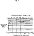
- FIG. 1 is an example of the PCT diagram of the hydrogen-absorbing alloy.
- FIG. 1 shows a desorption curve at 25°C.
- the desorption curve is a curve created by plotting the pressure when the hydrogen-absorbing alloy releases hydrogen with respect to the hydrogen composition of the hydrogen-absorbing alloy (the ratio of the number of hydrogen atoms to the number of metal atoms (H/M)).
- the pressure at which the hydrogen-absorbing alloy releases hydrogen is referred to as "dissociation pressure”.
- the region where the desorption curve is linear is referred to as “plateau region”.
- the dissociation pressure in the plateau region is referred to as the "plateau pressure”.
- the hydrogen-absorbing alloy can reversibly release hydrogen even under an environment where the pressure change is small (for example, in a sealed battery).
- the absorption and release of hydrogen in the hydrogen-absorbing alloy corresponds to charging and discharging of the negative electrode.
- FIG. 2 is the PCT diagram of the hydrogen-absorbing alloy in the related art.
- a hydrogen-absorbing alloy having a plateau pressure equal to or lower than the atmospheric pressure ( ⁇ 0.1MPa) at 25°C is used.
- such a hydrogen-absorbing alloy is referred to as a "low pressure type hydrogen-absorbing alloy”.
- the internal pressure of a sealed battery can be considered as the atmospheric pressure.
- the plateau pressure of the hydrogen-absorbing alloy is higher than the atmospheric pressure, spontaneous release of hydrogen easily occurs in the battery. That is, self-discharge of the battery is likely to occur.
- the internal pressure of the battery rises due to the release of hydrogen, it may become difficult to seal the battery. Therefore, a "high pressure type hydrogen-absorbing alloy" having a very high plateau pressure as shown in FIG. 1 has not attracted attention until now.
- a hydrogen-absorbing alloy having a plateau pressure at 25°C of 0.15 MPa or more and 10 MPa or less is used.
- the reversible hydrogen absorption amount is about 1.0 mass% to 1.1 mass%.
- the hydrogen-absorbing alloy used in this disclosure may have, for example, a hydrogen absorption amount of 1.3 mass% or more. That is, the hydrogen-absorbing alloy can become a negative electrode active material having a higher capacity than that of the low pressure type hydrogen-absorbing alloy.
- the hydrogen-absorbing alloy does not function as a high capacity negative electrode active material at around atmospheric pressure. That is, at around atmospheric pressure, the hydrogen-absorbing alloy cannot be fully charged. Therefore, the hydride secondary battery of this disclosure includes the pressure vessel and hydrogen gas (H 2 ). Hydrogen gas has a pressure equal to or higher than the plateau pressure of the hydrogen-absorbing alloy. Accordingly, in the hydride secondary battery of this disclosure, the hydrogen-absorbing alloy can function as a high capacity negative electrode active material. Accordingly, the mass capacity density of the battery is improved.
- the equilibrium negative electrode potential (discharge potential) of the hydride secondary battery of this disclosure is estimated by substituting the plateau pressure of the hydrogen-absorbing alloy into the Nernst equation.
- the hydrogen-absorbing alloy itself not only functions as a negative electrode active material but also as a catalyst for allowing hydrogen gas to become the second negative electrode active material. Accordingly, in the hydride secondary battery of this disclosure, two negative electrode reactions expressed by the following reaction equations proceed during discharge. At the time of charging, the reverse reaction proceeds.
- Hydrogen-absorbing alloy MH + OH - ⁇ M + H 2 O + e -
- Hydrogen gas 1/2H 2 + OH - ⁇ e - + H 2 O (in the equations, M represents the hydrogen-absorbing alloy and MH represents a hydride of the hydrogen-absorbing alloy.)
- the hydride secondary battery of this disclosure includes a hybrid negative electrode including a solid negative electrode active material (hydrogen-absorbing alloy) and a gaseous negative electrode active material (hydrogen gas).
- the gaseous negative electrode active material is lighter than the solid negative electrode active material. Therefore, the mass capacity density of the battery is further improved by the hybrid negative electrode.
- the hydride secondary battery of this disclosure has a high mass capacity density.
- A-site is Mm or lanthanum (La).
- B-site is occupied by nickel (Ni).
- the B-site may be occupied by Ni or a portion of Ni may be replaced with iron (Fe), chromium (Cr), manganese (Mn), aluminum (Al), or cobalt (Co).
- the plateau pressure is 0.15 MPa or more and 10 MPa or less, and the hydrogen absorption amount tends to be large. That is, since the hydrogen-absorbing alloy is the AB 5 type alloy, further improvement in the mass capacity density is expected.
- the hydrogen gas may have a pressure equal to or higher than the plateau pressure of the hydrogen-absorbing alloy.
- the pressure of hydrogen gas may be high as long as the sealing of hydrogen gas is possible. This is because as the hydrogen gas serving as the gaseous negative electrode active material is compressed at a high pressure, the improvement in the volumetric energy density (energy per unit volume) of the battery is expected.
- the hydrogen gas has a pressure of 20 MPa at 25°C
- the hydride secondary battery of this disclosure is estimated to exhibit a mass energy density of 180 Wh/kg and a volumetric energy density of 500 Wh/l.
- 70 MPa pressure vessels have also been developed.
- the positive electrode active material in the nickel positive electrode in a charged state, is nickel oxyhydroxide (NiOOH), and in the nickel positive electrode in a discharged state, the positive electrode active material is nickel hydroxide (Ni(OH) 2 ). Therefore, at any state of charge, the nickel positive electrode contains at least one of nickel oxyhydroxide and nickel hydroxide.
- the improvement in the operating voltage can be expected according to the plateau pressure of the hydrogen-absorbing alloy.
- the hydride secondary battery of this disclosure includes a nickel positive electrode, an operating voltage higher than that of the nickel-metal hydride secondary battery in the related art by about 0.01 V to 0.04 V can be expected.
- this embodiment an embodiment of this disclosure (hereinafter, referred to as “this embodiment”) will be described. However, the following description does not limit the scope of the invention of this disclosure.
- a high pressure type hydride secondary battery of this embodiment has a high mass capacity density. Therefore, the high pressure type hydride secondary battery of this embodiment is suitable as a power source for, for example, HV and electric vehicles (EV).
- the application of the high pressure type hydride secondary battery of this embodiment is not limited to such applications for vehicles.
- the high pressure type hydride secondary battery of this embodiment can be applied to any applications.
- FIG. 3 is a conceptual diagram illustrating the high pressure type hydride secondary battery according to this embodiment.
- a battery 100 includes a pressure vessel 50. In the pressure vessel 50, a positive electrode 10 and a negative electrode 20 are disposed. The positive electrode 10 and the negative electrode 20 are led out to the outside by lead wires.
- a separator 30 is disposed between the positive electrode 10 and the negative electrode 20. Although not illustrated, the positive electrode 10, the negative electrode 20, and the separator 30 are impregnated with an electrolyte. High pressure hydrogen gas is sealed in the space inside the pressure vessel 50.
- the battery 100 includes the pressure vessel 50, the positive electrode 10 disposed in the pressure vessel 50, the negative electrode 20 disposed in the pressure vessel 50, and the hydrogen gas with which the pressure vessel 50 is filled.
- the positive electrode 10 and the negative electrode 20 may be wound with the separator 30 interposed therebetween.
- the battery 100 may include a plurality of the positive electrodes 10 and a plurality of the negative electrodes 20.
- the positive electrodes 10 and the negative electrodes 20 may be alternately laminated with the separator 30 interposed therebetween.
- the structure of the pressure vessel 50 is not particularly limited as long as the pressure vessel 50 can withstand the pressure of the hydrogen gas.
- the wall of the pressure vessel 50 may have a multilayer structure.
- the multilayer structure may include a carbon fiber reinforced plastic (CFRP) layer.
- CFRP layer is expected to have pressure resistance.
- the multilayer structure may include at least one of a metal liner and a resin liner.
- the metal liner and the resin liner are expected to have an action of sealing the hydrogen gas. It is desirable that the metal liner is made of a material that is less likely to be affected by hydrogen gas.
- the metal liner is made of, for example, an Al alloy (Alloy 6061 or the like), or stainless steel (SUS316L or the like).
- the resin liner is made of, for example, polyamide (PA).
- the negative electrode 20 contains a hydrogen-absorbing alloy.
- the shape of the negative electrode 20 is not particularly limited.
- the negative electrode 20 may be, for example, a plate-like member.
- the planar shape of the negative electrode 20 may be a rectangular shape, a band shape, or the like.
- the negative electrode 20 may be, for example, a molded body of the hydrogen-absorbing alloy.
- the negative electrode 20 may be formed, for example, by coating a current collector with a negative electrode mixture material containing a powder-like hydrogen-absorbing alloy, a conductive material, and a binder. That is, the negative electrode 20 may contain a conductive material, a binder, a current collector, and the like as long as a hydrogen-absorbing alloy is contained therein.
- the conductive material may be metal powder such as copper (Cu) and Ni, carbon fiber, carbon powder such as carbon black, or the like.
- the binder may be, for example, polyvinyl alcohol (PVA), carboxymethyl cellulose (CMC), polyethylene (PE), styrene butadiene rubber (SBR), polytetrafluoroethylene (PTFE), or a copolymer of tetrafluoroethylene and hexafluoropropylene (FEP).
- the current collector may be, for example, punched metal, expanded metal, or foamed metal.
- the material of the current collector may be, for example, Ni or Fe plated with Ni.
- the negative electrode mixture material may contain, for example, 70 mass% to 98 mass% of the hydrogen-absorbing alloy, 1 mass% to 20 mass% of the conductive material, and 1 mass% to 10 mass% of the binder.
- the negative electrode 20 contains a high pressure type hydrogen-absorbing alloy. That is, in a PCT diagram, a desorption curve at 25°C of the hydrogen-absorbing alloy has a plateau pressure of 0.15 MPa or more and 10 MPa or less. The plateau pressure varies depending on the alloy composition of the hydrogen-absorbing alloy. As the plateau pressure increases, the improvement in the operating voltage of the battery can be expected.
- the plateau pressure may be, for example, 0.15 MPa or more and 5 MPa or less, 0.15 MPa or more and 2.3 MPa or less, 0.2 MPa or more and 2.3 MPa or less, or 0.3 MPa or more and 2.3 MPa or less, 0.57 MPa or more and 2.3 MPa or less, or 1.6 MPa or more and 2.3 MPa or less.
- the "desorption curve at 25°C” in this specification is measured by the method based on "JIS H 7201". In the measurement, a known Sieverts' instrument is used. During the measurement, when a thermometer disposed in a sample chamber (thermostat) indicates a temperature of 24°C to 26°C, it is assumed that the desorption curve at 25°C is measured.
- thermostat thermometer disposed in a sample chamber
- the vertical axis represents the dissociation pressure and the horizontal axis represents the hydrogen composition (H/M).
- the vertical axis has a common logarithmic scale.
- the hydrogen composition (H/M) represents the ratio (dimensionless number) of the number of hydrogen atoms to the number of metal atoms.
- the desorption curve at 25°C may be created by connecting at least 10 measurement points, and preferably 20 measurement points.
- the "plateau pressure" in this specification is calculated as follows. First, a straight line passing through three consecutive points in the desorption curve is drawn. The slope of the straight line is obtained. In a case where the three points do not lie on one straight line, the slope of the straight line is obtained by the least squares method. The combination of three points with the smallest slope is determined. The arithmetic average value of the dissociation pressures of the three points is regarded as the "plateau pressure".
- an absorption curve is also measured.
- the absorption curve is a curve created by plotting the pressure (absorption pressure) when the hydrogen-absorbing alloy absorbs hydrogen against the hydrogen composition.
- the absorption curve shifts to the higher pressure side than the desorption curve. Therefore, the fact that the desorption curve at 25°C has a plateau pressure of 0.15 MPa or more means that both the desorption curve and the absorption curve at 25°C have a plateau pressure of 0.15 MPa or more.
- Desorption curves and plateau pressures at other than 25°C may also be measured. From the plateau pressure at 25°C and the plateau pressures at the other temperatures, the standard enthalpy change and the standard entropy change when the hydrogen-absorbing alloy releases hydrogen are obtained. It is thought that the plateau pressure, the standard enthalpy change, and the standard entropy change satisfy the following relational equation.
- lnPH 2 ⁇ H / RT ⁇ ⁇ S / R (in the equation, PH 2 represents the plateau pressure, ⁇ H represents the standard enthalpy change, ⁇ S represents the standard entropy change, R represents the gas constant, and T represents the temperature at which the desorption curve is measured.) Therefore, since the natural logarithm of the plateau pressure (PH 2 ) is plotted against the reciprocal of the temperature (1/T), ⁇ H is obtained from the slope of the straight line, and ⁇ S is obtained from the intercept of the straight line.
- an AB type alloy an alloy having a CsCl type crystal structure
- an A 2 B type alloy an alloy having a Mg 2 Ni type crystal structure
- an AB 5 type alloy an alloy having a CaCu 5 type crystal structure
- the AB 5 type alloy can become the high pressure type hydrogen-absorbing alloy.
- the AB 5 type alloys expressed by Formulas (1) and (2) and LaNi 5 are high pressure type hydrogen-absorbing alloys and tend to have a large hydrogen absorption amount.
- MmNi 5-x1 B x1 (1) (in the formula, Mm represents the mischmetal, B represents at least one selected from the group consisting of Fe, Cr, Mn, and Al, and x1 is 0 or more and 0.6 or less.)
- MmNi 5-x2 Co x2 (2) (in the formula, Mm represents the mischmetal, and x2 is more than 0 and 1.0 or less.)
- the negative electrode 20 may contain one kind of hydrogen-absorbing alloy singly or may contain two or more kinds of hydrogen-absorbing alloy. Therefore, the hydrogen-absorbing alloy is at least one selected from the group consisting of (i) the AB 5 type alloy expressed by Formula (1), (ii) the AB 5 type alloy represented by Formula (2), and (iii) LaNi 5 .
- Mm represents a mixture of rare earth elements primarily containing cerium (Ce) and La. "Primarily containing Ce and La” means that the sum of Ce and La occupies 50 mass% or more of the entire mixture.
- Mm may contain neodymium (Nd), praseodymium (Pr), samarium (Sm), magnesium (Mg), Al, Fe, and the like.
- Mm contains, for example, 40 mass% to 60 mass% of Ce, 10 mass% to 35 mass% of La, and Nd, Pr, Sm, and the like as the remainder.
- Mm with a high content of La may also be used.
- the lanthanum-rich mischmetal contains, for example, 10 mass% to 30 mass% of Ce, 40 mass% to 70 mass% of La, and Nd, Pr, Sm, and the like as the remainder.
- Specific examples include Mm containing 25.8 mass% of Ce, 63.8 mass% of La, 7.9 mass% of Nd, and 2.4 mass% of Pr.
- the hydrogen-absorbing alloy may be an AB 5 type alloy expressed by Formula (3).
- MmNi 5-x3 Fe x3 (3) (in the formula, Mm represents the mischmetal, and x3 is 0.2 or more and 0.4 or less.)
- AB 5 type alloy expressed by Formula (3) for example, MmNi 4.7 Fe 0.3 or the like can be exemplified.
- the hydrogen-absorbing alloy may be an AB 5 type alloy expressed by Formula (4).
- MmNi 5-x4 Cr x4 (4) (in the formula, Mm represents the mischmetal, and x4 is 0.4 or more and 0.6 or less.)
- AB 5 type alloy expressed by Formula (4) for example, MmNi 4.5 Cr 0.5 or the like can be exemplified.
- the hydrogen-absorbing alloy may be an AB 5 type alloy expressed by Formula (5).
- MmNi 5-x5 Co x5 (5) (in the formula, Mm represents the mischmetal, and x5 is 0.7 or more and 0.9 or less.)
- AB 5 type alloy expressed by Formula (5) for example, MmNi 4.2 Co 0.8 or the like can be exemplified.
- the hydrogen-absorbing alloy may be an AB 5 type alloy expressed by Formula (6).
- MmNi 5-x6 Mn x6 (6) (in the formula, Mm represents the mischmetal, and x6 is 0.4 or more and 0.6 or less.)
- AB 5 type alloy expressed by Formula (6) for example, MmNi 4.5 Mn 0.5 or the like can be exemplified.
- the hydrogen-absorbing alloy may be an AB 5 type alloy expressed by Formula (7).
- MmNi 5-x7 Al x7 (7) (in the formula, Mm represents the mischmetal, and x7 is 0.4 or more and 0.6 or less.)
- AB 5 type alloy expressed by Formula (7) for example, MmNi 4.5 Al 0.5 or the like can be exemplified.
- the hydrogen-absorbing alloy may be an AB 5 type alloy expressed by Formula (8).
- Mm represents the mischmetal
- x8 is 0.25 or more and 0.45 or less
- y8 is 0.05 or more and 0.25 or less
- the sum of x8 and y8 is 0.5.
- Examples of the AB 5 type alloy expressed by Formula (8) include MmNi 4.5 Cr 0.45 Mn 0.05 and MmNi 4.5 Cr 0.25 Mn 0.25 .
- the hydrogen-absorbing alloy may be at least one selected from the group consisting of (i) MmNi 5 , (ii) the AB 5 type alloys expressed by Formulas (3) to (8), and (iii) LaNi 5 .
- the hydrogen-absorbing alloy may be at least one selected from the group consisting of MmNi 5 , MmNi 4.7 Fe 0.3 , MmNi 4.5 Cr 0.5 , MmNi 4.2 Co 0.8 , MmNi 4.5 Mn 0.5 , MmNi 4.5 Al 0.5, MmNi 4.5 Cr 0.45 Mn 0.05 , MmNi 4.5 Cr 0.25 Mn 0.25 , and LaNi 5 .
- the "hydrogen absorption amount” represents the ratio of the mass of hydrogen to the mass of the alloy in a state where all the alloys are hydrogenated.
- the high pressure type hydrogen-absorbing alloy can have, for example, a hydrogen absorption amount of 1.3 mass% or more and 1.5 mass% or less. Furthermore, the high pressure type hydrogen-absorbing alloy may also have a hydrogen absorption amount of 1.4 mass% or more and 1.5 mass% or less.
- the pressure vessel 50 is filled with the hydrogen gas.
- Hydrogen gas has a pressure equal to or higher than the plateau pressure at 25°C of the high pressure type hydrogen-absorbing alloy. Accordingly, the high pressure type hydrogen-absorbing alloy can function as a high-capacity negative electrode active material.
- the pressure of the hydrogen gas is measured with a pressure gauge. It is natural that the pressure gauge should be selected as appropriate depending on the pressure of the hydrogen gas, the form of the pressure vessel 50, and the like. For example, a pressure gauge for high pressure hydrogen gas at 70 MPa is also commercially available. The pressure gauge may be permanently installed in the pressure vessel 50.
- the hydrogen gas of this embodiment functions as the negative electrode active material, thereby contributing to the improvement in the mass capacity density of the battery 100.
- the hydrogen gas preferably has a pressure of 10 MPa or more and 70 MPa or less at 25°C. As the hydrogen gas (the negative electrode active material) is compressed, the improvement in the volumetric energy density of the battery 100 is expected. At 25°C, the hydrogen gas has a pressure of more preferably 20 MPa or more and 70 MPa or less, even more preferably 40 MPa or more and 70 MPa or less, and most preferably 60 MPa or more and 70 MPa or less.
- the positive electrode 10 contains a positive electrode active material.
- the shape of the positive electrode 10 is also not particularly limited.
- the positive electrode 10 may also be, for example, a plate-like member.
- the planar shape of the positive electrode 10 may also be a rectangular shape, a band shape, or the like.
- the positive electrode active material may be, for example, at least one of NiOOH and Ni(OH) 2 . That is, the positive electrode 10 may be a nickel positive electrode.
- the nickel positive electrode may be a sintered nickel positive electrode well known in the related art, or may be a paste type nickel positive electrode.
- the positive electrode 10 may be formed by filling a base material such as foamed Ni with a positive electrode mixture material containing the positive electrode active material, a conductive material, and a binder.
- the conductive material may be, for example, cobalt oxide (CoO), or cobalt hydroxide (Co(OH) 2 ).
- the binder may be, for example, PVA, CMC, SBR, PTFE, or FEP.
- the positive electrode mixture material contains, for example, 80 mass% to 98 mass% of the positive electrode active material, 1 mass% to 10 mass% of the conductive material, and 1 mass% to 10 mass% of the binder.
- the separator 30 is disposed between the positive electrode 10 and the negative electrode 20.
- the separator 30 may be, for example, a nonwoven fabric made of polypropylene (PP), or a nonwoven fabric made of polyamide (PA).
- the nonwoven fabric may be subjected to a treatment for imparting hydrophilicity to the surface of the fiber. Examples of the treatment for imparting hydrophilicity include a sulfonation treatment and a plasma treatment.
- the nonwoven fabric has, for example, a thickness of about 50 ⁇ m to 500 ⁇ m.
- the nonwoven fabric has, for example, a basis weight of about 50 g/m 2 to 100 g/m 2 .
- the electrolyte may be, for example, a potassium hydroxide (KOH) aqueous solution.
- KOH potassium hydroxide
- the electrolyte may contain, in addition to KOH, sodium hydroxide (NaOH), lithium hydroxide (LiOH), and the like.
- concentration of hydroxide ions (OH - ) in the electrolyte may be, for example, about 1 mol/l to 20 mol/l.
- water contained in the electrolyte may be electrolyzed during charging, and hydrogen gas may be generated.
- the inside of the pressure vessel 50 is filled with the high pressure hydrogen gas. Therefore, it is expected that electrolysis of water will hardly proceed due to Le Chatelier's principle.
- a Mm powder and a Ni powder were prepared.
- the mixed powder was dissolved in an arc melting furnace under an argon atmosphere. Accordingly, a molten alloy was prepared.
- the molten alloy was cooled by a strip casting method. Accordingly, a cast piece of a hydrogen-absorbing alloy (MmNi 5 ) was obtained. The case piece was crushed by a ball mill. Accordingly, a powder of the hydrogen-absorbing alloy (AB 5 type alloy) was prepared.
- the powder had a particle size of 20 ⁇ m to 100 ⁇ m.
- test cell including a test electrode containing a powder of a hydrogen-absorbing alloy and a test electrode was produced according to the procedure based on "JIS H 7205".
- a test cell a pressure vessel capable of withstanding the same pressure as the plateau pressure of the hydrogen-absorbing alloy was used, and the pressure vessel was filled with hydrogen gas so that the internal pressure of the pressure vessel was equal to or higher than the plateau pressure.
- Other configurations of the test cell are as follows.
- Sample Nos. 1 to 9 were the high pressure type hydrogen-absorbing alloys having a plateau pressure of 0.15 MPa or more and 10 MPa or less.
- Sample Nos. 10 to 13 were low pressure type hydrogen-absorbing alloys having a plateau pressure of less than 0.15 MPa.
- test cells that is, the high pressure type hydride secondary batteries
- the test cells including the high pressure type hydrogen-absorbing alloys (Sample Nos. 1 to 9) had a higher mass capacity density than the test cells including the low pressure type hydrogen-absorbing alloys (Sample Nos. 10 to 13).
Landscapes
- Chemical & Material Sciences (AREA)
- Chemical Kinetics & Catalysis (AREA)
- Engineering & Computer Science (AREA)
- Electrochemistry (AREA)
- General Chemical & Material Sciences (AREA)
- Organic Chemistry (AREA)
- Manufacturing & Machinery (AREA)
- Materials Engineering (AREA)
- Mechanical Engineering (AREA)
- Metallurgy (AREA)
- Inorganic Chemistry (AREA)
- Combustion & Propulsion (AREA)
- Life Sciences & Earth Sciences (AREA)
- Environmental & Geological Engineering (AREA)
- General Life Sciences & Earth Sciences (AREA)
- Geology (AREA)
- Battery Electrode And Active Subsutance (AREA)
- Secondary Cells (AREA)
Abstract
Description
- This disclosure relates to a hydride secondary battery.
-
WO2009/037806 discloses an AB5 type hydrogen-absorbing alloy. - A nickel-metal hydride secondary battery (Ni-MH) in which a hydrogen-absorbing alloy is used as a negative electrode active material and nickel oxyhydroxide is used as a positive electrode active material has been put to practical use. The nickel-metal hydride secondary battery has been widely used as a power source for consumer electronics. Moreover, in recent years, the nickel-metal hydride secondary battery has also been used as a power source for electric vehicles such as hybrid vehicles (HV).
- For power applications in mobile bodies including power sources for electric vehicles, the mass capacity density (capacity per unit mass) of a secondary battery is important. With the expansion of power applications, a further increase in the mass capacity density of the secondary battery is preferable.
- Therefore, this disclosure provides a secondary battery having a high mass capacity density.
- [1] A hydride secondary battery of this disclosure includes: a pressure vessel; a positive electrode disposed in the pressure vessel; a negative electrode disposed in the pressure vessel; and hydrogen gas with which the pressure vessel is filled. The negative electrode contains a hydrogen-absorbing alloy. In a pressure-composition-temperature diagram, a desorption curve at 25°C of the hydrogen-absorbing alloy has a plateau pressure of 0.15 MPa or more and 10 MPa or less. The hydrogen gas has a pressure equal to or higher than the plateau pressure at 25°C of the hydrogen-absorbing alloy.
- The pressure-composition-temperature diagram (hereinafter, referred to as "PCT diagram") shows the basic characteristics of the hydrogen-absorbing alloy.
FIG. 1 is an example of the PCT diagram of the hydrogen-absorbing alloy.FIG. 1 shows a desorption curve at 25°C. - The desorption curve is a curve created by plotting the pressure when the hydrogen-absorbing alloy releases hydrogen with respect to the hydrogen composition of the hydrogen-absorbing alloy (the ratio of the number of hydrogen atoms to the number of metal atoms (H/M)). The pressure at which the hydrogen-absorbing alloy releases hydrogen is referred to as "dissociation pressure". The region where the desorption curve is linear is referred to as "plateau region". The dissociation pressure in the plateau region is referred to as the "plateau pressure".
- In the plateau region, the pressure change with the release of hydrogen is small. Therefore, in the plateau region, the hydrogen-absorbing alloy can reversibly release hydrogen even under an environment where the pressure change is small (for example, in a sealed battery). In the nickel-metal hydride secondary battery, the absorption and release of hydrogen in the hydrogen-absorbing alloy corresponds to charging and discharging of the negative electrode.
-
FIG. 2 is the PCT diagram of the hydrogen-absorbing alloy in the related art. In a nickel-metal hydride secondary battery in the related art, as shown inFIG. 2 , a hydrogen-absorbing alloy having a plateau pressure equal to or lower than the atmospheric pressure (≈0.1MPa) at 25°C is used. Hereinafter, such a hydrogen-absorbing alloy is referred to as a "low pressure type hydrogen-absorbing alloy". - Typically, the internal pressure of a sealed battery can be considered as the atmospheric pressure. When the plateau pressure of the hydrogen-absorbing alloy is higher than the atmospheric pressure, spontaneous release of hydrogen easily occurs in the battery. That is, self-discharge of the battery is likely to occur. In addition, since the internal pressure of the battery rises due to the release of hydrogen, it may become difficult to seal the battery. Therefore, a "high pressure type hydrogen-absorbing alloy" having a very high plateau pressure as shown in
FIG. 1 has not attracted attention until now. - In the hydride secondary battery of this disclosure, a hydrogen-absorbing alloy having a plateau pressure at 25°C of 0.15 MPa or more and 10 MPa or less is used. In the low pressure type hydrogen-absorbing alloy, the reversible hydrogen absorption amount is about 1.0 mass% to 1.1 mass%. Contrary to this, the hydrogen-absorbing alloy used in this disclosure may have, for example, a hydrogen absorption amount of 1.3 mass% or more. That is, the hydrogen-absorbing alloy can become a negative electrode active material having a higher capacity than that of the low pressure type hydrogen-absorbing alloy.
- However, the hydrogen-absorbing alloy does not function as a high capacity negative electrode active material at around atmospheric pressure. That is, at around atmospheric pressure, the hydrogen-absorbing alloy cannot be fully charged. Therefore, the hydride secondary battery of this disclosure includes the pressure vessel and hydrogen gas (H2). Hydrogen gas has a pressure equal to or higher than the plateau pressure of the hydrogen-absorbing alloy. Accordingly, in the hydride secondary battery of this disclosure, the hydrogen-absorbing alloy can function as a high capacity negative electrode active material. Accordingly, the mass capacity density of the battery is improved.
- Here, the equilibrium negative electrode potential (discharge potential) of the hydride secondary battery of this disclosure is estimated by substituting the plateau pressure of the hydrogen-absorbing alloy into the Nernst equation. The equilibrium negative electrode potential is calculated by the following equation.

- From this equation, it is thought that the equilibrium negative electrode potential decreases as the plateau pressure increases. That is, it is thought that the operating voltage of the battery increases. Therefore, in the hydride secondary battery of this disclosure, the improvement in the mass energy density (energy per unit mass) can also be expected. Here, "energy" represents the product of the average operating voltage of the battery and the battery capacity.
- Furthermore, in the hydride secondary battery of this disclosure, the hydrogen-absorbing alloy itself not only functions as a negative electrode active material but also as a catalyst for allowing hydrogen gas to become the second negative electrode active material. Accordingly, in the hydride secondary battery of this disclosure, two negative electrode reactions expressed by the following reaction equations proceed during discharge. At the time of charging, the reverse reaction proceeds.
Hydrogen-absorbing alloy: MH + OH- → M + H2O + e-
Hydrogen gas: 1/2H2 + OH- → e- + H2O
(in the equations, M represents the hydrogen-absorbing alloy and MH represents a hydride of the hydrogen-absorbing alloy.) - That is, the hydride secondary battery of this disclosure includes a hybrid negative electrode including a solid negative electrode active material (hydrogen-absorbing alloy) and a gaseous negative electrode active material (hydrogen gas). The gaseous negative electrode active material is lighter than the solid negative electrode active material. Therefore, the mass capacity density of the battery is further improved by the hybrid negative electrode. As described above, the hydride secondary battery of this disclosure has a high mass capacity density.
- [2] The desorption curve at 25°C of the hydrogen-absorbing alloy may have a plateau pressure of 0.15 MPa or more and 5 MPa or less.
- [3] The desorption curve at 25°C of the hydrogen-absorbing alloy may have a plateau pressure of 0.3 MPa or more and 2.3 MPa or less.
- [4] the hydrogen-absorbing alloy may be at least one selected from the group consisting of an AB5 type alloy expressed by MmNi5-x1Bx1, provided that Mm represents a mischmetal, B represents at least one selected from the group consisting of Fe, Cr, Mn, and Al, and x1 is 0 or more and 0.6 or less, an AB5 type alloy expressed by MmNi5-x2Cox2, provided that Mm represents a mischmetal and x2 is more than 0 and 1.0 or less, and LaNi5.
- In the above AB5 type alloys, A-site is Mm or lanthanum (La). In a case where the A-site is La, B-site is occupied by nickel (Ni). In a case where the A-site is Mm, the B-site may be occupied by Ni or a portion of Ni may be replaced with iron (Fe), chromium (Cr), manganese (Mn), aluminum (Al), or cobalt (Co). In such an AB5 type alloy, the plateau pressure is 0.15 MPa or more and 10 MPa or less, and the hydrogen absorption amount tends to be large. That is, since the hydrogen-absorbing alloy is the AB5 type alloy, further improvement in the mass capacity density is expected.
- [5] The hydrogen-absorbing alloy may be at least one selected from the group consisting of an AB5 type alloy expressed by MmNi5-x3Fex3, provided that Mm represents a mischmetal and x3 is 0.2 or more and 0.4 or less, an AB5 type alloy expressed by MmNi5-x4Crx4, provided that Mm represents a mischmetal and x4 is 0.4 or more and 0.6 or less, an AB5 type alloy expressed by MmNi5-x5Cox5, provided that Mm represents a mischmetal and x5 is 0.7 or more and 0.9 or less, an AB5 type alloy expressed by MmNi5-x6Mnx6, provided that Mm represents a mischmetal and x6 is 0.4 or more and 0.6 or less, an AB5 type alloy expressed by MmNi5-x7pAlx7, provided that Mm represents a mischmetal and x7 is 0.4 or more and 0.6 or less, and an AB5 type alloy expressed by MmNi5-x8-y8Crx8Mny8, provided that Mm represents a mischmetal, x8 is 0.25 or more and 0.45 or less, y8 is 0.05 or more and 0.25 or less, and the sum of x8 and y8 is 0.5.
- [6] The hydrogen-absorbing alloy may be at least one selected from the group consisting of MmNi5, MmNi4.7Fe0.3, MmNi4.5Cr0.5, MmNi4.2Co0.8, MmNi4.5Mn0.5, MmNi4.5Al0.5, MmNi4.5Cr0.45Mn0.05, and MmNi4.5Cr0.25Mn0.25, provided that Mm represents a mischmetal.
- [7] The AB5 type alloy according to [2] may have a hydrogen absorption amount of 1.3 mass% or more and 1.5 mass% or less.
- [8] The hydrogen gas may have a pressure at 25°C of 10 MPa or more and 70 MPa or less.
- Since the hydrogen-absorbing alloy functions as a high capacity negative electrode active material, the hydrogen gas may have a pressure equal to or higher than the plateau pressure of the hydrogen-absorbing alloy. Here, the pressure of hydrogen gas may be high as long as the sealing of hydrogen gas is possible. This is because as the hydrogen gas serving as the gaseous negative electrode active material is compressed at a high pressure, the improvement in the volumetric energy density (energy per unit volume) of the battery is expected. For example, in a case where the hydrogen gas has a pressure of 20 MPa at 25°C, the hydride secondary battery of this disclosure is estimated to exhibit a mass energy density of 180 Wh/kg and a volumetric energy density of 500 Wh/l. In addition, as a high pressure hydrogen tank for fuel cells, 70 MPa pressure vessels have also been developed.
- [9] The positive electrode may contain at least one of nickel oxyhydroxide and nickel hydroxide. That is, the positive electrode may be a nickel positive electrode. In a case where the positive electrode is the nickel positive electrode, in the hydride secondary battery, the reactions expressed by the following reaction equations proceed during discharging (the reverse reactions proceed during charging).
- As shown in the above reaction equations, in the nickel positive electrode in a charged state, the positive electrode active material is nickel oxyhydroxide (NiOOH), and in the nickel positive electrode in a discharged state, the positive electrode active material is nickel hydroxide (Ni(OH)2). Therefore, at any state of charge, the nickel positive electrode contains at least one of nickel oxyhydroxide and nickel hydroxide.
- As described above, in the hydride secondary battery of this disclosure, the improvement in the operating voltage can be expected according to the plateau pressure of the hydrogen-absorbing alloy. In a case where the hydride secondary battery of this disclosure includes a nickel positive electrode, an operating voltage higher than that of the nickel-metal hydride secondary battery in the related art by about 0.01 V to 0.04 V can be expected.
- Features, advantages, and technical and industrial significance of exemplary embodiments of the invention will be described below with reference to the accompanying drawings, in which like numerals denote like elements, and wherein:
-
FIG. 1 is an example of the PCT diagram of a hydrogen-absorbing alloy; -
FIG. 2 is the PCT diagram of the hydrogen-absorbing alloy in the related art; and -
FIG. 3 is a conceptual diagram illustrating a high pressure type hydride secondary battery according to an embodiment of this disclosure. - Hereinafter, an embodiment of this disclosure (hereinafter, referred to as "this embodiment") will be described. However, the following description does not limit the scope of the invention of this disclosure.
- A high pressure type hydride secondary battery of this embodiment has a high mass capacity density. Therefore, the high pressure type hydride secondary battery of this embodiment is suitable as a power source for, for example, HV and electric vehicles (EV). However, the application of the high pressure type hydride secondary battery of this embodiment is not limited to such applications for vehicles. The high pressure type hydride secondary battery of this embodiment can be applied to any applications.
- Hereinafter, the high pressure type hydride secondary battery is abbreviated as "battery" in some cases.
FIG. 3 is a conceptual diagram illustrating the high pressure type hydride secondary battery according to this embodiment. Abattery 100 includes apressure vessel 50. In thepressure vessel 50, apositive electrode 10 and anegative electrode 20 are disposed. Thepositive electrode 10 and thenegative electrode 20 are led out to the outside by lead wires. A separator 30 is disposed between thepositive electrode 10 and thenegative electrode 20. Although not illustrated, thepositive electrode 10, thenegative electrode 20, and the separator 30 are impregnated with an electrolyte. High pressure hydrogen gas is sealed in the space inside thepressure vessel 50. - That is, the
battery 100 includes thepressure vessel 50, thepositive electrode 10 disposed in thepressure vessel 50, thenegative electrode 20 disposed in thepressure vessel 50, and the hydrogen gas with which thepressure vessel 50 is filled. Thepositive electrode 10 and thenegative electrode 20 may be wound with the separator 30 interposed therebetween. Thebattery 100 may include a plurality of thepositive electrodes 10 and a plurality of thenegative electrodes 20. For example, thepositive electrodes 10 and thenegative electrodes 20 may be alternately laminated with the separator 30 interposed therebetween. - The structure of the
pressure vessel 50 is not particularly limited as long as thepressure vessel 50 can withstand the pressure of the hydrogen gas. For example, the wall of thepressure vessel 50 may have a multilayer structure. The multilayer structure may include a carbon fiber reinforced plastic (CFRP) layer. The CFRP layer is expected to have pressure resistance. The multilayer structure may include at least one of a metal liner and a resin liner. The metal liner and the resin liner are expected to have an action of sealing the hydrogen gas. It is desirable that the metal liner is made of a material that is less likely to be affected by hydrogen gas. The metal liner is made of, for example, an Al alloy (Alloy 6061 or the like), or stainless steel (SUS316L or the like). The resin liner is made of, for example, polyamide (PA). - The
negative electrode 20 contains a hydrogen-absorbing alloy. The shape of thenegative electrode 20 is not particularly limited. Thenegative electrode 20 may be, for example, a plate-like member. The planar shape of thenegative electrode 20 may be a rectangular shape, a band shape, or the like. Thenegative electrode 20 may be, for example, a molded body of the hydrogen-absorbing alloy Thenegative electrode 20 may be formed, for example, by coating a current collector with a negative electrode mixture material containing a powder-like hydrogen-absorbing alloy, a conductive material, and a binder. That is, thenegative electrode 20 may contain a conductive material, a binder, a current collector, and the like as long as a hydrogen-absorbing alloy is contained therein. - The conductive material may be metal powder such as copper (Cu) and Ni, carbon fiber, carbon powder such as carbon black, or the like. The binder may be, for example, polyvinyl alcohol (PVA), carboxymethyl cellulose (CMC), polyethylene (PE), styrene butadiene rubber (SBR), polytetrafluoroethylene (PTFE), or a copolymer of tetrafluoroethylene and hexafluoropropylene (FEP). The current collector may be, for example, punched metal, expanded metal, or foamed metal. The material of the current collector may be, for example, Ni or Fe plated with Ni. The negative electrode mixture material may contain, for example, 70 mass% to 98 mass% of the hydrogen-absorbing alloy, 1 mass% to 20 mass% of the conductive material, and 1 mass% to 10 mass% of the binder.
- In this embodiment, the
negative electrode 20 contains a high pressure type hydrogen-absorbing alloy. That is, in a PCT diagram, a desorption curve at 25°C of the hydrogen-absorbing alloy has a plateau pressure of 0.15 MPa or more and 10 MPa or less. The plateau pressure varies depending on the alloy composition of the hydrogen-absorbing alloy. As the plateau pressure increases, the improvement in the operating voltage of the battery can be expected. The plateau pressure may be, for example, 0.15 MPa or more and 5 MPa or less, 0.15 MPa or more and 2.3 MPa or less, 0.2 MPa or more and 2.3 MPa or less, or 0.3 MPa or more and 2.3 MPa or less, 0.57 MPa or more and 2.3 MPa or less, or 1.6 MPa or more and 2.3 MPa or less. - The "desorption curve at 25°C" in this specification is measured by the method based on "JIS H 7201". In the measurement, a known Sieverts' instrument is used. During the measurement, when a thermometer disposed in a sample chamber (thermostat) indicates a temperature of 24°C to 26°C, it is assumed that the desorption curve at 25°C is measured.
- As illustrated in
FIG. 1 , in the PCT diagram, the vertical axis represents the dissociation pressure and the horizontal axis represents the hydrogen composition (H/M). The vertical axis has a common logarithmic scale. As described above, the hydrogen composition (H/M) represents the ratio (dimensionless number) of the number of hydrogen atoms to the number of metal atoms. The desorption curve at 25°C may be created by connecting at least 10 measurement points, and preferably 20 measurement points. - The "plateau pressure" in this specification is calculated as follows. First, a straight line passing through three consecutive points in the desorption curve is drawn. The slope of the straight line is obtained. In a case where the three points do not lie on one straight line, the slope of the straight line is obtained by the least squares method. The combination of three points with the smallest slope is determined. The arithmetic average value of the dissociation pressures of the three points is regarded as the "plateau pressure".
- Typically, in a case where the desorption curve is measured, an absorption curve is also measured. The absorption curve is a curve created by plotting the pressure (absorption pressure) when the hydrogen-absorbing alloy absorbs hydrogen against the hydrogen composition. In general, the absorption curve shifts to the higher pressure side than the desorption curve. Therefore, the fact that the desorption curve at 25°C has a plateau pressure of 0.15 MPa or more means that both the desorption curve and the absorption curve at 25°C have a plateau pressure of 0.15 MPa or more.
- Desorption curves and plateau pressures at other than 25°C may also be measured. From the plateau pressure at 25°C and the plateau pressures at the other temperatures, the standard enthalpy change and the standard entropy change when the hydrogen-absorbing alloy releases hydrogen are obtained. It is thought that the plateau pressure, the standard enthalpy change, and the standard entropy change satisfy the following relational equation.

- As the hydrogen-absorbing alloy, an AB type alloy (an alloy having a CsCl type crystal structure), an A2B type alloy (an alloy having a Mg2Ni type crystal structure), an AB5 type alloy (an alloy having a CaCu5 type crystal structure), and the like are known. Among them, the AB5 type alloy can become the high pressure type hydrogen-absorbing alloy. Furthermore, the AB5 type alloys expressed by Formulas (1) and (2) and LaNi5 are high pressure type hydrogen-absorbing alloys and tend to have a large hydrogen absorption amount.
MmNi5-x1Bx1 (1)
(in the formula, Mm represents the mischmetal, B represents at least one selected from the group consisting of Fe, Cr, Mn, and Al, and x1 is 0 or more and 0.6 or less.)
MmNi5-x2Cox2 (2)
(in the formula, Mm represents the mischmetal, and x2 is more than 0 and 1.0 or less.) - The
negative electrode 20 may contain one kind of hydrogen-absorbing alloy singly or may contain two or more kinds of hydrogen-absorbing alloy. Therefore, the hydrogen-absorbing alloy is at least one selected from the group consisting of (i) the AB5 type alloy expressed by Formula (1), (ii) the AB5 type alloy represented by Formula (2), and (iii) LaNi5. - The "mischmetal (Mm)" represents a mixture of rare earth elements primarily containing cerium (Ce) and La. "Primarily containing Ce and La" means that the sum of Ce and La occupies 50 mass% or more of the entire mixture. In addition to Ce and La, Mm may contain neodymium (Nd), praseodymium (Pr), samarium (Sm), magnesium (Mg), Al, Fe, and the like. Mm contains, for example, 40 mass% to 60 mass% of Ce, 10 mass% to 35 mass% of La, and Nd, Pr, Sm, and the like as the remainder. Specific examples include Mm containing 53.7 mass% of Ce, 24.1 mass% of La, 16.5 mass% of Nd, and 5.8 mass% Pr. Mm with a high content of La (so-called "lanthanum-rich mischmetal") may also be used. The lanthanum-rich mischmetal contains, for example, 10 mass% to 30 mass% of Ce, 40 mass% to 70 mass% of La, and Nd, Pr, Sm, and the like as the remainder. Specific examples include Mm containing 25.8 mass% of Ce, 63.8 mass% of La, 7.9 mass% of Nd, and 2.4 mass% of Pr.
- The hydrogen-absorbing alloy may be an AB5 type alloy expressed by Formula (3).
MmNi5-x3Fex3 (3)
(in the formula, Mm represents the mischmetal, and x3 is 0.2 or more and 0.4 or less.) - As the AB5 type alloy expressed by Formula (3), for example, MmNi4.7Fe0.3 or the like can be exemplified.
- The hydrogen-absorbing alloy may be an AB5 type alloy expressed by Formula (4).
MmNi5-x4Crx4 (4)
(in the formula, Mm represents the mischmetal, and x4 is 0.4 or more and 0.6 or less.) - As the AB5 type alloy expressed by Formula (4), for example, MmNi4.5Cr0.5 or the like can be exemplified.
- The hydrogen-absorbing alloy may be an AB5 type alloy expressed by Formula (5).
MmNi5-x5Cox5 (5)
(in the formula, Mm represents the mischmetal, and x5 is 0.7 or more and 0.9 or less.) - As the AB5 type alloy expressed by Formula (5), for example, MmNi4.2Co0.8 or the like can be exemplified.
- The hydrogen-absorbing alloy may be an AB5 type alloy expressed by Formula (6).
MmNi5-x6Mnx6 (6)
(in the formula, Mm represents the mischmetal, and x6 is 0.4 or more and 0.6 or less.) - As the AB5 type alloy expressed by Formula (6), for example, MmNi4.5Mn0.5 or the like can be exemplified.
- The hydrogen-absorbing alloy may be an AB5 type alloy expressed by Formula (7).
MmNi5-x7Alx7 (7)
(in the formula, Mm represents the mischmetal, and x7 is 0.4 or more and 0.6 or less.) - As the AB5 type alloy expressed by Formula (7), for example, MmNi4.5Al0.5 or the like can be exemplified.
- The hydrogen-absorbing alloy may be an AB5 type alloy expressed by Formula (8).
MmNi5-x8-y8Crx8Mny8 (8)
- (In the formula, Mm represents the mischmetal, x8 is 0.25 or more and 0.45 or less, y8 is 0.05 or more and 0.25 or less, and the sum of x8 and y8 is 0.5.)
- Examples of the AB5 type alloy expressed by Formula (8) include MmNi4.5Cr0.45Mn0.05 and MmNi4.5Cr0.25Mn0.25.
- Therefore, the hydrogen-absorbing alloy may be at least one selected from the group consisting of (i) MmNi5, (ii) the AB5 type alloys expressed by Formulas (3) to (8), and (iii) LaNi5.
- Alternatively, the hydrogen-absorbing alloy may be at least one selected from the group consisting of MmNi5, MmNi4.7Fe0.3, MmNi4.5Cr0.5, MmNi4.2Co0.8, MmNi4.5Mn0.5, MmNi4.5Al0.5, MmNi4.5Cr0.45Mn0.05, MmNi4.5Cr0.25Mn0.25, and LaNi5.
- As the hydrogen absorption amount of the hydrogen-absorbing alloy increases, the improvement in the mass capacity density of the
battery 100 can be expected. The "hydrogen absorption amount" represents the ratio of the mass of hydrogen to the mass of the alloy in a state where all the alloys are hydrogenated. The high pressure type hydrogen-absorbing alloy can have, for example, a hydrogen absorption amount of 1.3 mass% or more and 1.5 mass% or less. Furthermore, the high pressure type hydrogen-absorbing alloy may also have a hydrogen absorption amount of 1.4 mass% or more and 1.5 mass% or less. - The
pressure vessel 50 is filled with the hydrogen gas. Hydrogen gas has a pressure equal to or higher than the plateau pressure at 25°C of the high pressure type hydrogen-absorbing alloy. Accordingly, the high pressure type hydrogen-absorbing alloy can function as a high-capacity negative electrode active material. The pressure of the hydrogen gas is measured with a pressure gauge. It is natural that the pressure gauge should be selected as appropriate depending on the pressure of the hydrogen gas, the form of thepressure vessel 50, and the like. For example, a pressure gauge for high pressure hydrogen gas at 70 MPa is also commercially available. The pressure gauge may be permanently installed in thepressure vessel 50. - The hydrogen gas of this embodiment functions as the negative electrode active material, thereby contributing to the improvement in the mass capacity density of the
battery 100. The hydrogen gas preferably has a pressure of 10 MPa or more and 70 MPa or less at 25°C. As the hydrogen gas (the negative electrode active material) is compressed, the improvement in the volumetric energy density of thebattery 100 is expected. At 25°C, the hydrogen gas has a pressure of more preferably 20 MPa or more and 70 MPa or less, even more preferably 40 MPa or more and 70 MPa or less, and most preferably 60 MPa or more and 70 MPa or less. - The
positive electrode 10 contains a positive electrode active material. The shape of thepositive electrode 10 is also not particularly limited. Thepositive electrode 10 may also be, for example, a plate-like member. The planar shape of thepositive electrode 10 may also be a rectangular shape, a band shape, or the like. The positive electrode active material may be, for example, at least one of NiOOH and Ni(OH)2. That is, thepositive electrode 10 may be a nickel positive electrode. The nickel positive electrode may be a sintered nickel positive electrode well known in the related art, or may be a paste type nickel positive electrode. For example, thepositive electrode 10 may be formed by filling a base material such as foamed Ni with a positive electrode mixture material containing the positive electrode active material, a conductive material, and a binder. The conductive material may be, for example, cobalt oxide (CoO), or cobalt hydroxide (Co(OH)2). The binder may be, for example, PVA, CMC, SBR, PTFE, or FEP. The positive electrode mixture material contains, for example, 80 mass% to 98 mass% of the positive electrode active material, 1 mass% to 10 mass% of the conductive material, and 1 mass% to 10 mass% of the binder. - The separator 30 is disposed between the
positive electrode 10 and thenegative electrode 20. The separator 30 may be, for example, a nonwoven fabric made of polypropylene (PP), or a nonwoven fabric made of polyamide (PA). The nonwoven fabric may be subjected to a treatment for imparting hydrophilicity to the surface of the fiber. Examples of the treatment for imparting hydrophilicity include a sulfonation treatment and a plasma treatment. The nonwoven fabric has, for example, a thickness of about 50 µm to 500 µm. The nonwoven fabric has, for example, a basis weight of about 50 g/m2 to 100 g/m2. - Voids in the
positive electrode 10, thenegative electrode 20, and the separator 30 are impregnated with the electrolyte. The electrolyte may be, for example, a potassium hydroxide (KOH) aqueous solution. The electrolyte may contain, in addition to KOH, sodium hydroxide (NaOH), lithium hydroxide (LiOH), and the like. The concentration of hydroxide ions (OH-) in the electrolyte may be, for example, about 1 mol/l to 20 mol/l. - In a nickel-metal hydride secondary battery in the related art, water contained in the electrolyte may be electrolyzed during charging, and hydrogen gas may be generated. In the high pressure type hydride secondary battery of this embodiment, the inside of the
pressure vessel 50 is filled with the high pressure hydrogen gas. Therefore, it is expected that electrolysis of water will hardly proceed due to Le Chatelier's principle. - Hereinafter, examples will be described. However, the following examples do not limit the scope of the invention of this disclosure.
- Various hydrogen-absorbing alloys were prepared in the following manner.
- A Mm powder and a Ni powder were prepared. The Mm powder and the Ni powder were mixed in a molar ratio of "Mm : Ni = 1 : 5". Accordingly, a mixed powder was prepared. The mixed powder was dissolved in an arc melting furnace under an argon atmosphere. Accordingly, a molten alloy was prepared. The molten alloy was cooled by a strip casting method. Accordingly, a cast piece of a hydrogen-absorbing alloy (MmNi5) was obtained. The case piece was crushed by a ball mill. Accordingly, a powder of the hydrogen-absorbing alloy (AB5 type alloy) was prepared. The powder had a particle size of 20 µm to 100 µm.
- As shown in Table 1 below, powders of hydrogen-absorbing alloys according to Sample Nos. 2 to 13 were prepared in the same procedure as Sample No. 1 except that the alloy composition was changed.
Table 1 Sample list Sample No. Hydrogen-absorbing alloy Test cell Alloy composition Plateau pressure (25°C) [MPa] Hydrogen absorption amount [mass%] ΔH [kJ/mol H2] ΔS [J/K·mol H2] Mass capacity density [mAh/g] Voltage [V] 1 MmNi5 2.3 1.5 -21.1 -97 400 1.26 2 MmNi4.7Fe0.3 1.6 1.4 -22 -97 370 1.25 3 MmNi4.5Cr0.5 0.57 1.3 -25.5 -100 340 1.24 4 MmNi4.2Co0.8 2.1 1.5 -23.8 -105 400 1.26 5 MmNi4.5Mn0.5 0.33 1.5 -28 -104 400 1.23 6 MmNi4.5Al0.5 0.38 1.3 -28 -105 340 1.24 7 MmNi4.5Cr0.4Mn0.05 0.30 1.5 -30 -104 400 1.23 8 MmNi4.5Cr0.25Mn0.25 0.20 1.5 -30 -105 390 1.22 9 LaNi5 0.15 1.4 -31 -108 370 1.22 10 MmNi4.2Cr0.2Mn0.5Al0.3 0.02 1.1 -37 -109 300 1.20 11 MmMNi4.0Fe1.0 0.10 1.0 -29 -99 270 1.22 12 MmNi4.2Mn0.8 0.10 1.0 -28 -95 270 1.22 13 MmNi4.1Al0.9 0.10 1.0 -33 -105 260 1.22 - A test cell (hydride secondary battery) including a test electrode containing a powder of a hydrogen-absorbing alloy and a test electrode was produced according to the procedure based on "JIS H 7205". Here, as the container for the test cell, a pressure vessel capable of withstanding the same pressure as the plateau pressure of the hydrogen-absorbing alloy was used, and the pressure vessel was filled with hydrogen gas so that the internal pressure of the pressure vessel was equal to or higher than the plateau pressure. Other configurations of the test cell are as follows.
-
- Counter electrode: nickel hydroxide
- Electrolyte: KOH aqueous solution (6 mol/l)
- Separator: nonwoven fabric made of PP
- By the method described above, desorption curves at 25°C were measured. Furthermore, a PCT diagram was created. For the measurement, a Sieverts' instrument manufactured by Suzuki Shokan Co., Ltd. was used. Plateau pressures, hydrogen absorption amounts, ΔH, and ΔS were calculated. The results are shown in Table 1 above.
- As shown in Table 1 above, Sample Nos. 1 to 9 were the high pressure type hydrogen-absorbing alloys having a plateau pressure of 0.15 MPa or more and 10 MPa or less. Sample Nos. 10 to 13 were low pressure type hydrogen-absorbing alloys having a plateau pressure of less than 0.15 MPa.
- The discharge characteristics and voltages of the test cells were measured by the procedure based on "JIS H 7205". Accordingly, the mass capacity density of the hydrogen-absorbing alloy was obtained. The results are shown in Table 1 above.
- As shown in Table 1 above, the test cells (that is, the high pressure type hydride secondary batteries) including the high pressure type hydrogen-absorbing alloys (Sample Nos. 1 to 9) had a higher mass capacity density than the test cells including the low pressure type hydrogen-absorbing alloys (Sample Nos. 10 to 13).
- The embodiments and examples disclosed herein are examples in all respects and should not be considered restrictive. The scope of the invention of this disclosure should be indicated not by the embodiments and examples described above but by the claims. The scope of the invention of this disclosure is intended to include meanings equivalent to claims and all changes within the scope.
(+) NiOOH + H2O + e- → Ni(OH)2 + OH-
(-) MH + OH- → M + H2O + e-
(-) 1/2H2 + OH- → e- + H2O
(in the equations, (+) represents a positive electrode reaction, and (-) represents a negative electrode reaction.)
Claims (9)
- A hydride secondary battery (100) comprising:a pressure vessel (50);a positive electrode (10) disposed in the pressure vessel (50);a negative electrode (20) disposed in the pressure vessel (50); andhydrogen gas with which the pressure vessel (50) is filled,wherein the negative electrode (20) contains a hydrogen-absorbing alloy, and in a pressure-composition-temperature diagram, a desorption curve at 25°C of the hydrogen-absorbing alloy has a plateau pressure of 0.15 MPa or more and 10 MPa or less, andwherein the hydrogen gas has a pressure equal to or higher than the plateau pressure at 25°C of the hydrogen-absorbing alloy.
- The hydride secondary battery (100) according to claim 1, wherein the desorption curve at 25°C of the hydrogen-absorbing alloy has a plateau pressure of 0.15 MPa or more and 5 MPa or less.
- The hydride secondary battery (100) according to claim 1, wherein the desorption curve at 25°C of the hydrogen-absorbing alloy has a plateau pressure of 0.3 MPa or more and 2.3 MPa or less.
- The hydride secondary battery (100) according to any one of claims 1 to 3, wherein the hydrogen-absorbing alloy is at least one selected from the group consisting of a AB5 type alloy expressed by MmNi5-x1Bx1, provided that Mm represents a mischmetal, B represents at least one selected from the group consisting of Fe, Cr, Mn, and Al, and x1 is 0 or more and 0.6 or less, a AB5 type alloy expressed by MmNi5-x2Cox2, provided that Mm represents a mischmetal and x2 is more than 0 and 1.0 or less, and LaNi5.
- The hydride secondary battery (100) according to any one of claims 1 to 3, wherein the hydrogen-absorbing alloy is at least one selected from the group consisting of
an AB5 type alloy expressed by MmNi5-x3Fex3, provided that Mm represents a mischmetal and x3 is 0.2 or more and 0.4 or less,
an AB5 type alloy expressed by MmNi5-x4Crx4, provided that Mm represents a mischmetal and x4 is 0.4 or more and 0.6 or less,
an AB5 type alloy expressed by MmNi5-x5Cox5, provided that Mm represents a mischmetal and x5 is 0.7 or more and 0.9 or less,
an AB5 type alloy expressed by MmNi5-x6Mnx6, provided that Mm represents a mischmetal and x6 is 0.4 or more and 0.6 or less,
an AB5 type alloy expressed by MmNi5-x7Alx7, provided that Mm represents a mischmetal and x7 is 0.4 or more and 0.6 or less, and
an AB5 type alloy expressed by MmNi5-x8-y8Crx8Mny8, provided that Mm represents a mischmetal, x8 is 0.25 or more and 0.45 or less, y8 is 0.05 or more and 0.25 or less, and a sum of x8 and y8 is 0.5. - The hydride secondary battery (100) according to any one of claims 1 to 3, wherein the hydrogen-absorbing alloy is at least one selected from the group consisting of MmNi5, MmNi4.7Fe0.3, MmNi4.5Cr0.5, MmNi4.2Co0.8, MmNi4.5Mn0.5, MmNi4.5Al0.5, MmNi4.5Cr0.45Mn0.05, and MmNi4.5Cr0.25Mn0.25, provided that Mm represents a mischmetal.
- The hydride secondary battery (100) according to any one of claims 4 to 6, wherein the hydrogen-absorbing alloy has a hydrogen absorption amount of 1.3 mass% or more and 1.5 mass% or less.
- The hydride secondary battery (100) according to any one of claims 1 to 7, wherein the hydrogen gas has a pressure at 25°C of 10 MPa or more and 70 MPa or less.
- The hydride secondary battery (100) according to any one of claims 1 to 8, wherein the positive electrode (10) contains at least one of nickel oxyhydroxide and nickel hydroxide.
Applications Claiming Priority (1)
| Application Number | Priority Date | Filing Date | Title |
|---|---|---|---|
| JP2016181602A JP6606041B2 (en) | 2016-09-16 | 2016-09-16 | High-pressure hydride secondary battery |
Publications (2)
| Publication Number | Publication Date |
|---|---|
| EP3297071A1 true EP3297071A1 (en) | 2018-03-21 |
| EP3297071B1 EP3297071B1 (en) | 2020-02-26 |
Family
ID=59846487
Family Applications (1)
| Application Number | Title | Priority Date | Filing Date |
|---|---|---|---|
| EP17190371.9A Active EP3297071B1 (en) | 2016-09-16 | 2017-09-11 | High pressure type hydride secondary battery |
Country Status (5)
| Country | Link |
|---|---|
| US (1) | US10923780B2 (en) |
| EP (1) | EP3297071B1 (en) |
| JP (1) | JP6606041B2 (en) |
| KR (1) | KR101968416B1 (en) |
| CN (1) | CN107834055B (en) |
Families Citing this family (3)
| Publication number | Priority date | Publication date | Assignee | Title |
|---|---|---|---|---|
| CN109449543A (en) * | 2018-10-23 | 2019-03-08 | 清华大学深圳研究生院 | A kind of gas negative battery and preparation method thereof |
| JP6746116B2 (en) * | 2019-01-08 | 2020-08-26 | エクセルギー・パワー・システムズ株式会社 | Secondary battery for mobile |
| JP7248531B2 (en) * | 2019-07-22 | 2023-03-29 | トヨタ自動車株式会社 | Hydrogen gas production device, hydrogen gas production method, and hydrogen storage alloy |
Citations (2)
| Publication number | Priority date | Publication date | Assignee | Title |
|---|---|---|---|---|
| WO2002021626A1 (en) * | 2000-09-07 | 2002-03-14 | Norsk Hydro Asa | Prezzurized metal hydride batteries |
| WO2009037806A1 (en) | 2007-09-19 | 2009-03-26 | Panasonic Corporation | Cathode activating substance for nickel-hydrogen cell, nickel-hydrogen cell using the substance, and method for treating the nickel-hydrogen cell cathode activating substance |
Family Cites Families (7)
| Publication number | Priority date | Publication date | Assignee | Title |
|---|---|---|---|---|
| NL6906305A (en) * | 1969-01-24 | 1970-10-27 | ||
| FR2569059B1 (en) * | 1984-08-10 | 1992-08-07 | Sanyo Electric Co | ALKALINE METAL / HYDROGEN ACCUMULATOR |
| KR920010422B1 (en) * | 1987-05-15 | 1992-11-27 | 마쯔시다덴기산교 가부시기가이샤 | Hydrogen Absorption Storage Electrode and Manufacturing Method Thereof |
| CN1029809C (en) * | 1991-12-28 | 1995-09-20 | 南开大学 | Hydrogen Storage Alloy Electrode |
| JPH0817433A (en) * | 1994-06-28 | 1996-01-19 | Hitachi Maxell Ltd | Nickel hydride secondary battery |
| JP5648772B1 (en) * | 2014-02-10 | 2015-01-07 | エクセルギー・パワー・システムズ株式会社 | Alkaline secondary battery |
| CN105390755B (en) * | 2015-11-05 | 2018-10-16 | 衡阳电科电源有限公司 | A kind of Ni-MH battery and preparation method thereof |
-
2016
- 2016-09-16 JP JP2016181602A patent/JP6606041B2/en active Active
-
2017
- 2017-09-05 CN CN201710789539.3A patent/CN107834055B/en active Active
- 2017-09-11 EP EP17190371.9A patent/EP3297071B1/en active Active
- 2017-09-13 US US15/703,121 patent/US10923780B2/en active Active
- 2017-09-13 KR KR1020170116953A patent/KR101968416B1/en active Active
Patent Citations (2)
| Publication number | Priority date | Publication date | Assignee | Title |
|---|---|---|---|---|
| WO2002021626A1 (en) * | 2000-09-07 | 2002-03-14 | Norsk Hydro Asa | Prezzurized metal hydride batteries |
| WO2009037806A1 (en) | 2007-09-19 | 2009-03-26 | Panasonic Corporation | Cathode activating substance for nickel-hydrogen cell, nickel-hydrogen cell using the substance, and method for treating the nickel-hydrogen cell cathode activating substance |
Non-Patent Citations (1)
| Title |
|---|
| LOTOTSKYY M V ET AL: "Metal hydride hydrogen compressors: A review", INTERNATIONAL JOURNAL OF HYDROGEN ENERGY, vol. 39, no. 11, 26 February 2014 (2014-02-26), pages 5818 - 5851, XP028832525, ISSN: 0360-3199, DOI: 10.1016/J.IJHYDENE.2014.01.158 * |
Also Published As
| Publication number | Publication date |
|---|---|
| KR20180030757A (en) | 2018-03-26 |
| US10923780B2 (en) | 2021-02-16 |
| CN107834055B (en) | 2021-06-11 |
| JP6606041B2 (en) | 2019-11-13 |
| JP2018045942A (en) | 2018-03-22 |
| US20180083324A1 (en) | 2018-03-22 |
| EP3297071B1 (en) | 2020-02-26 |
| KR101968416B1 (en) | 2019-04-11 |
| CN107834055A (en) | 2018-03-23 |
Similar Documents
| Publication | Publication Date | Title |
|---|---|---|
| US9105947B2 (en) | Hydrogen storage alloy for alkaline storage battery, and alkaline storage battery and alkaline storage battery system each including negative electrode having the alloy | |
| ES2902407T3 (en) | Hydrogen occlusion alloy, negative electrode including hydrogen occlusion alloy, and nickel-hydrogen secondary battery including negative electrode | |
| EP3297071B1 (en) | High pressure type hydride secondary battery | |
| US20170141401A1 (en) | Positive electrode active material for nickel-hydrogen secondary battery, nickel-hydrogen secondary battery including the positive electrode active material, and method of evaluating positive electrode active material | |
| KR102009599B1 (en) | Alkaline secondary battery | |
| EP3483960B1 (en) | Negative electrode for nickel hydrogen secondary battery, and nickel hydrogen secondary battery including the negative electrode | |
| KR20180046353A (en) | Anode material and battery | |
| JP2005105356A (en) | Hydrogen storage alloy, hydrogen storage alloy electrode and sealed nickel-metal hydride storage battery | |
| JP2013134903A (en) | Hydrogen absorbing alloy for alkaline storage battery, and alkaline storage battery including the same | |
| JP4183292B2 (en) | Secondary battery | |
| JP2005290473A (en) | Hydrogen occlusion alloy, hydrogen occlusion alloy particle and secondary battery | |
| JP7092639B2 (en) | Alkaline secondary battery | |
| JP2566912B2 (en) | Nickel oxide / hydrogen battery | |
| JP7323441B2 (en) | Hydrogen storage alloys and metal hydride batteries | |
| JP6951047B2 (en) | Alkaline secondary battery | |
| JPH0810596B2 (en) | Metal oxide / hydrogen battery | |
| JP6866230B2 (en) | Nickel metal hydride battery | |
| JPH0677450B2 (en) | Sealed nickel-hydrogen battery | |
| KR0158034B1 (en) | Method for manufacturing electrode for the secondary battery by using the v-ti alloy | |
| JPS61292855A (en) | Metal oxide and hydrogen cell | |
| JP3560352B2 (en) | Metal oxide / hydrogen secondary batteries | |
| JP2974802B2 (en) | Hydride rechargeable battery | |
| JPH0517659B2 (en) | ||
| KR20190043086A (en) | Positive electrode and alkaline secondary battery including the same | |
| 王志兴 et al. | Electrochemical Properties of Sn Doped AB_5 Non-Stoichiometric Hydrogen Absorbing Alloys-Ⅱ |
Legal Events
| Date | Code | Title | Description |
|---|---|---|---|
| PUAI | Public reference made under article 153(3) epc to a published international application that has entered the european phase |
Free format text: ORIGINAL CODE: 0009012 |
|
| STAA | Information on the status of an ep patent application or granted ep patent |
Free format text: STATUS: REQUEST FOR EXAMINATION WAS MADE |
|
| 17P | Request for examination filed |
Effective date: 20170911 |
|
| AK | Designated contracting states |
Kind code of ref document: A1 Designated state(s): AL AT BE BG CH CY CZ DE DK EE ES FI FR GB GR HR HU IE IS IT LI LT LU LV MC MK MT NL NO PL PT RO RS SE SI SK SM TR |
|
| AX | Request for extension of the european patent |
Extension state: BA ME |
|
| STAA | Information on the status of an ep patent application or granted ep patent |
Free format text: STATUS: EXAMINATION IS IN PROGRESS |
|
| 17Q | First examination report despatched |
Effective date: 20190315 |
|
| RIC1 | Information provided on ipc code assigned before grant |
Ipc: B22F 9/04 20060101ALI20190821BHEP Ipc: C22C 19/00 20060101ALI20190821BHEP Ipc: H01M 4/02 20060101ALN20190821BHEP Ipc: H01M 4/24 20060101AFI20190821BHEP Ipc: C22C 19/03 20060101ALI20190821BHEP Ipc: H01M 10/34 20060101ALI20190821BHEP Ipc: H01M 4/32 20060101ALI20190821BHEP Ipc: C22C 1/04 20060101ALI20190821BHEP Ipc: C22C 19/05 20060101ALI20190821BHEP Ipc: H01M 4/38 20060101ALI20190821BHEP |
|
| GRAP | Despatch of communication of intention to grant a patent |
Free format text: ORIGINAL CODE: EPIDOSNIGR1 |
|
| STAA | Information on the status of an ep patent application or granted ep patent |
Free format text: STATUS: GRANT OF PATENT IS INTENDED |
|
| INTG | Intention to grant announced |
Effective date: 20190930 |
|
| GRAS | Grant fee paid |
Free format text: ORIGINAL CODE: EPIDOSNIGR3 |
|
| GRAA | (expected) grant |
Free format text: ORIGINAL CODE: 0009210 |
|
| STAA | Information on the status of an ep patent application or granted ep patent |
Free format text: STATUS: THE PATENT HAS BEEN GRANTED |
|
| AK | Designated contracting states |
Kind code of ref document: B1 Designated state(s): AL AT BE BG CH CY CZ DE DK EE ES FI FR GB GR HR HU IE IS IT LI LT LU LV MC MK MT NL NO PL PT RO RS SE SI SK SM TR |
|
| REG | Reference to a national code |
Ref country code: GB Ref legal event code: FG4D |
|
| REG | Reference to a national code |
Ref country code: CH Ref legal event code: EP |
|
| REG | Reference to a national code |
Ref country code: AT Ref legal event code: REF Ref document number: 1238743 Country of ref document: AT Kind code of ref document: T Effective date: 20200315 |
|
| REG | Reference to a national code |
Ref country code: IE Ref legal event code: FG4D |
|
| REG | Reference to a national code |
Ref country code: DE Ref legal event code: R096 Ref document number: 602017012182 Country of ref document: DE |
|
| PG25 | Lapsed in a contracting state [announced via postgrant information from national office to epo] |
Ref country code: FI Free format text: LAPSE BECAUSE OF FAILURE TO SUBMIT A TRANSLATION OF THE DESCRIPTION OR TO PAY THE FEE WITHIN THE PRESCRIBED TIME-LIMIT Effective date: 20200226 Ref country code: RS Free format text: LAPSE BECAUSE OF FAILURE TO SUBMIT A TRANSLATION OF THE DESCRIPTION OR TO PAY THE FEE WITHIN THE PRESCRIBED TIME-LIMIT Effective date: 20200226 Ref country code: NO Free format text: LAPSE BECAUSE OF FAILURE TO SUBMIT A TRANSLATION OF THE DESCRIPTION OR TO PAY THE FEE WITHIN THE PRESCRIBED TIME-LIMIT Effective date: 20200526 |
|
| REG | Reference to a national code |
Ref country code: NL Ref legal event code: MP Effective date: 20200226 |
|
| REG | Reference to a national code |
Ref country code: LT Ref legal event code: MG4D |
|
| PG25 | Lapsed in a contracting state [announced via postgrant information from national office to epo] |
Ref country code: GR Free format text: LAPSE BECAUSE OF FAILURE TO SUBMIT A TRANSLATION OF THE DESCRIPTION OR TO PAY THE FEE WITHIN THE PRESCRIBED TIME-LIMIT Effective date: 20200527 Ref country code: BG Free format text: LAPSE BECAUSE OF FAILURE TO SUBMIT A TRANSLATION OF THE DESCRIPTION OR TO PAY THE FEE WITHIN THE PRESCRIBED TIME-LIMIT Effective date: 20200526 Ref country code: HR Free format text: LAPSE BECAUSE OF FAILURE TO SUBMIT A TRANSLATION OF THE DESCRIPTION OR TO PAY THE FEE WITHIN THE PRESCRIBED TIME-LIMIT Effective date: 20200226 Ref country code: LV Free format text: LAPSE BECAUSE OF FAILURE TO SUBMIT A TRANSLATION OF THE DESCRIPTION OR TO PAY THE FEE WITHIN THE PRESCRIBED TIME-LIMIT Effective date: 20200226 Ref country code: SE Free format text: LAPSE BECAUSE OF FAILURE TO SUBMIT A TRANSLATION OF THE DESCRIPTION OR TO PAY THE FEE WITHIN THE PRESCRIBED TIME-LIMIT Effective date: 20200226 Ref country code: IS Free format text: LAPSE BECAUSE OF FAILURE TO SUBMIT A TRANSLATION OF THE DESCRIPTION OR TO PAY THE FEE WITHIN THE PRESCRIBED TIME-LIMIT Effective date: 20200626 |
|
| PG25 | Lapsed in a contracting state [announced via postgrant information from national office to epo] |
Ref country code: NL Free format text: LAPSE BECAUSE OF FAILURE TO SUBMIT A TRANSLATION OF THE DESCRIPTION OR TO PAY THE FEE WITHIN THE PRESCRIBED TIME-LIMIT Effective date: 20200226 |
|
| PG25 | Lapsed in a contracting state [announced via postgrant information from national office to epo] |
Ref country code: SK Free format text: LAPSE BECAUSE OF FAILURE TO SUBMIT A TRANSLATION OF THE DESCRIPTION OR TO PAY THE FEE WITHIN THE PRESCRIBED TIME-LIMIT Effective date: 20200226 Ref country code: LT Free format text: LAPSE BECAUSE OF FAILURE TO SUBMIT A TRANSLATION OF THE DESCRIPTION OR TO PAY THE FEE WITHIN THE PRESCRIBED TIME-LIMIT Effective date: 20200226 Ref country code: RO Free format text: LAPSE BECAUSE OF FAILURE TO SUBMIT A TRANSLATION OF THE DESCRIPTION OR TO PAY THE FEE WITHIN THE PRESCRIBED TIME-LIMIT Effective date: 20200226 Ref country code: DK Free format text: LAPSE BECAUSE OF FAILURE TO SUBMIT A TRANSLATION OF THE DESCRIPTION OR TO PAY THE FEE WITHIN THE PRESCRIBED TIME-LIMIT Effective date: 20200226 Ref country code: SM Free format text: LAPSE BECAUSE OF FAILURE TO SUBMIT A TRANSLATION OF THE DESCRIPTION OR TO PAY THE FEE WITHIN THE PRESCRIBED TIME-LIMIT Effective date: 20200226 Ref country code: EE Free format text: LAPSE BECAUSE OF FAILURE TO SUBMIT A TRANSLATION OF THE DESCRIPTION OR TO PAY THE FEE WITHIN THE PRESCRIBED TIME-LIMIT Effective date: 20200226 Ref country code: ES Free format text: LAPSE BECAUSE OF FAILURE TO SUBMIT A TRANSLATION OF THE DESCRIPTION OR TO PAY THE FEE WITHIN THE PRESCRIBED TIME-LIMIT Effective date: 20200226 Ref country code: CZ Free format text: LAPSE BECAUSE OF FAILURE TO SUBMIT A TRANSLATION OF THE DESCRIPTION OR TO PAY THE FEE WITHIN THE PRESCRIBED TIME-LIMIT Effective date: 20200226 Ref country code: PT Free format text: LAPSE BECAUSE OF FAILURE TO SUBMIT A TRANSLATION OF THE DESCRIPTION OR TO PAY THE FEE WITHIN THE PRESCRIBED TIME-LIMIT Effective date: 20200719 |
|
| REG | Reference to a national code |
Ref country code: AT Ref legal event code: MK05 Ref document number: 1238743 Country of ref document: AT Kind code of ref document: T Effective date: 20200226 |
|
| REG | Reference to a national code |
Ref country code: DE Ref legal event code: R097 Ref document number: 602017012182 Country of ref document: DE |
|
| PLBE | No opposition filed within time limit |
Free format text: ORIGINAL CODE: 0009261 |
|
| STAA | Information on the status of an ep patent application or granted ep patent |
Free format text: STATUS: NO OPPOSITION FILED WITHIN TIME LIMIT |
|
| PG25 | Lapsed in a contracting state [announced via postgrant information from national office to epo] |
Ref country code: AT Free format text: LAPSE BECAUSE OF FAILURE TO SUBMIT A TRANSLATION OF THE DESCRIPTION OR TO PAY THE FEE WITHIN THE PRESCRIBED TIME-LIMIT Effective date: 20200226 Ref country code: IT Free format text: LAPSE BECAUSE OF FAILURE TO SUBMIT A TRANSLATION OF THE DESCRIPTION OR TO PAY THE FEE WITHIN THE PRESCRIBED TIME-LIMIT Effective date: 20200226 |
|
| 26N | No opposition filed |
Effective date: 20201127 |
|
| PG25 | Lapsed in a contracting state [announced via postgrant information from national office to epo] |
Ref country code: SI Free format text: LAPSE BECAUSE OF FAILURE TO SUBMIT A TRANSLATION OF THE DESCRIPTION OR TO PAY THE FEE WITHIN THE PRESCRIBED TIME-LIMIT Effective date: 20200226 Ref country code: PL Free format text: LAPSE BECAUSE OF FAILURE TO SUBMIT A TRANSLATION OF THE DESCRIPTION OR TO PAY THE FEE WITHIN THE PRESCRIBED TIME-LIMIT Effective date: 20200226 |
|
| REG | Reference to a national code |
Ref country code: DE Ref legal event code: R084 Ref document number: 602017012182 Country of ref document: DE |
|
| REG | Reference to a national code |
Ref country code: CH Ref legal event code: PL |
|
| REG | Reference to a national code |
Ref country code: BE Ref legal event code: MM Effective date: 20200930 |
|
| PG25 | Lapsed in a contracting state [announced via postgrant information from national office to epo] |
Ref country code: LU Free format text: LAPSE BECAUSE OF NON-PAYMENT OF DUE FEES Effective date: 20200911 |
|
| PG25 | Lapsed in a contracting state [announced via postgrant information from national office to epo] |
Ref country code: FR Free format text: LAPSE BECAUSE OF NON-PAYMENT OF DUE FEES Effective date: 20200930 |
|
| PG25 | Lapsed in a contracting state [announced via postgrant information from national office to epo] |
Ref country code: CH Free format text: LAPSE BECAUSE OF NON-PAYMENT OF DUE FEES Effective date: 20200930 Ref country code: BE Free format text: LAPSE BECAUSE OF NON-PAYMENT OF DUE FEES Effective date: 20200930 Ref country code: LI Free format text: LAPSE BECAUSE OF NON-PAYMENT OF DUE FEES Effective date: 20200930 Ref country code: IE Free format text: LAPSE BECAUSE OF NON-PAYMENT OF DUE FEES Effective date: 20200911 |
|
| GBPC | Gb: european patent ceased through non-payment of renewal fee |
Effective date: 20210911 |
|
| PG25 | Lapsed in a contracting state [announced via postgrant information from national office to epo] |
Ref country code: TR Free format text: LAPSE BECAUSE OF FAILURE TO SUBMIT A TRANSLATION OF THE DESCRIPTION OR TO PAY THE FEE WITHIN THE PRESCRIBED TIME-LIMIT Effective date: 20200226 Ref country code: MT Free format text: LAPSE BECAUSE OF FAILURE TO SUBMIT A TRANSLATION OF THE DESCRIPTION OR TO PAY THE FEE WITHIN THE PRESCRIBED TIME-LIMIT Effective date: 20200226 Ref country code: CY Free format text: LAPSE BECAUSE OF FAILURE TO SUBMIT A TRANSLATION OF THE DESCRIPTION OR TO PAY THE FEE WITHIN THE PRESCRIBED TIME-LIMIT Effective date: 20200226 |
|
| PG25 | Lapsed in a contracting state [announced via postgrant information from national office to epo] |
Ref country code: MK Free format text: LAPSE BECAUSE OF FAILURE TO SUBMIT A TRANSLATION OF THE DESCRIPTION OR TO PAY THE FEE WITHIN THE PRESCRIBED TIME-LIMIT Effective date: 20200226 Ref country code: MC Free format text: LAPSE BECAUSE OF FAILURE TO SUBMIT A TRANSLATION OF THE DESCRIPTION OR TO PAY THE FEE WITHIN THE PRESCRIBED TIME-LIMIT Effective date: 20200226 Ref country code: AL Free format text: LAPSE BECAUSE OF FAILURE TO SUBMIT A TRANSLATION OF THE DESCRIPTION OR TO PAY THE FEE WITHIN THE PRESCRIBED TIME-LIMIT Effective date: 20200226 |
|
| PG25 | Lapsed in a contracting state [announced via postgrant information from national office to epo] |
Ref country code: GB Free format text: LAPSE BECAUSE OF NON-PAYMENT OF DUE FEES Effective date: 20210911 |
|
| PGFP | Annual fee paid to national office [announced via postgrant information from national office to epo] |
Ref country code: DE Payment date: 20250730 Year of fee payment: 9 |