EP3297058A1 - Medical device battery assembly and medical device unit - Google Patents
Medical device battery assembly and medical device unit Download PDFInfo
- Publication number
- EP3297058A1 EP3297058A1 EP16792663.3A EP16792663A EP3297058A1 EP 3297058 A1 EP3297058 A1 EP 3297058A1 EP 16792663 A EP16792663 A EP 16792663A EP 3297058 A1 EP3297058 A1 EP 3297058A1
- Authority
- EP
- European Patent Office
- Prior art keywords
- battery
- medical instrument
- casing
- battery assembly
- electrode layer
- Prior art date
- Legal status (The legal status is an assumption and is not a legal conclusion. Google has not performed a legal analysis and makes no representation as to the accuracy of the status listed.)
- Withdrawn
Links
- 239000007784 solid electrolyte Substances 0.000 claims abstract description 26
- 238000003475 lamination Methods 0.000 claims abstract description 12
- 239000000758 substrate Substances 0.000 claims description 10
- 239000012636 effector Substances 0.000 claims description 6
- 239000000463 material Substances 0.000 description 14
- 238000012986 modification Methods 0.000 description 8
- 230000004048 modification Effects 0.000 description 8
- 238000003825 pressing Methods 0.000 description 6
- 230000002238 attenuated effect Effects 0.000 description 5
- 239000013013 elastic material Substances 0.000 description 4
- 239000011149 active material Substances 0.000 description 3
- 230000005540 biological transmission Effects 0.000 description 3
- 239000003792 electrolyte Substances 0.000 description 3
- 239000002001 electrolyte material Substances 0.000 description 3
- 230000035939 shock Effects 0.000 description 3
- 239000000126 substance Substances 0.000 description 3
- 239000010409 thin film Substances 0.000 description 3
- PPBRXRYQALVLMV-UHFFFAOYSA-N Styrene Chemical compound C=CC1=CC=CC=C1 PPBRXRYQALVLMV-UHFFFAOYSA-N 0.000 description 2
- UCKMPCXJQFINFW-UHFFFAOYSA-N Sulphide Chemical compound [S-2] UCKMPCXJQFINFW-UHFFFAOYSA-N 0.000 description 2
- 238000005452 bending Methods 0.000 description 2
- 230000005489 elastic deformation Effects 0.000 description 2
- 239000007788 liquid Substances 0.000 description 2
- 238000000034 method Methods 0.000 description 2
- 238000005192 partition Methods 0.000 description 2
- 239000011148 porous material Substances 0.000 description 2
- 239000011347 resin Substances 0.000 description 2
- 229920005989 resin Polymers 0.000 description 2
- 239000007787 solid Substances 0.000 description 2
- 239000002388 carbon-based active material Substances 0.000 description 1
- 230000005674 electromagnetic induction Effects 0.000 description 1
- 239000002184 metal Substances 0.000 description 1
- 229910021645 metal ion Inorganic materials 0.000 description 1
- 239000007769 metal material Substances 0.000 description 1
- 150000004767 nitrides Chemical class 0.000 description 1
- 239000004033 plastic Substances 0.000 description 1
- 238000009774 resonance method Methods 0.000 description 1
- 238000009210 therapy by ultrasound Methods 0.000 description 1
Images




Classifications
-
- A—HUMAN NECESSITIES
- A61—MEDICAL OR VETERINARY SCIENCE; HYGIENE
- A61B—DIAGNOSIS; SURGERY; IDENTIFICATION
- A61B18/00—Surgical instruments, devices or methods for transferring non-mechanical forms of energy to or from the body
- A61B18/04—Surgical instruments, devices or methods for transferring non-mechanical forms of energy to or from the body by heating
- A61B18/08—Surgical instruments, devices or methods for transferring non-mechanical forms of energy to or from the body by heating by means of electrically-heated probes
- A61B18/10—Power sources therefor
-
- A—HUMAN NECESSITIES
- A61—MEDICAL OR VETERINARY SCIENCE; HYGIENE
- A61B—DIAGNOSIS; SURGERY; IDENTIFICATION
- A61B1/00—Instruments for performing medical examinations of the interior of cavities or tubes of the body by visual or photographical inspection, e.g. endoscopes; Illuminating arrangements therefor
- A61B1/00002—Operational features of endoscopes
- A61B1/00025—Operational features of endoscopes characterised by power management
- A61B1/00027—Operational features of endoscopes characterised by power management characterised by power supply
- A61B1/00032—Operational features of endoscopes characterised by power management characterised by power supply internally powered
-
- A—HUMAN NECESSITIES
- A61—MEDICAL OR VETERINARY SCIENCE; HYGIENE
- A61B—DIAGNOSIS; SURGERY; IDENTIFICATION
- A61B17/00—Surgical instruments, devices or methods
-
- A—HUMAN NECESSITIES
- A61—MEDICAL OR VETERINARY SCIENCE; HYGIENE
- A61B—DIAGNOSIS; SURGERY; IDENTIFICATION
- A61B17/00—Surgical instruments, devices or methods
- A61B17/32—Surgical cutting instruments
- A61B17/320068—Surgical cutting instruments using mechanical vibrations, e.g. ultrasonic
-
- A—HUMAN NECESSITIES
- A61—MEDICAL OR VETERINARY SCIENCE; HYGIENE
- A61B—DIAGNOSIS; SURGERY; IDENTIFICATION
- A61B18/00—Surgical instruments, devices or methods for transferring non-mechanical forms of energy to or from the body
- A61B18/04—Surgical instruments, devices or methods for transferring non-mechanical forms of energy to or from the body by heating
- A61B18/12—Surgical instruments, devices or methods for transferring non-mechanical forms of energy to or from the body by heating by passing a current through the tissue to be heated, e.g. high-frequency current
-
- H—ELECTRICITY
- H01—ELECTRIC ELEMENTS
- H01M—PROCESSES OR MEANS, e.g. BATTERIES, FOR THE DIRECT CONVERSION OF CHEMICAL ENERGY INTO ELECTRICAL ENERGY
- H01M10/00—Secondary cells; Manufacture thereof
- H01M10/05—Accumulators with non-aqueous electrolyte
-
- H—ELECTRICITY
- H01—ELECTRIC ELEMENTS
- H01M—PROCESSES OR MEANS, e.g. BATTERIES, FOR THE DIRECT CONVERSION OF CHEMICAL ENERGY INTO ELECTRICAL ENERGY
- H01M10/00—Secondary cells; Manufacture thereof
- H01M10/05—Accumulators with non-aqueous electrolyte
- H01M10/056—Accumulators with non-aqueous electrolyte characterised by the materials used as electrolytes, e.g. mixed inorganic/organic electrolytes
- H01M10/0561—Accumulators with non-aqueous electrolyte characterised by the materials used as electrolytes, e.g. mixed inorganic/organic electrolytes the electrolyte being constituted of inorganic materials only
- H01M10/0562—Solid materials
-
- A—HUMAN NECESSITIES
- A61—MEDICAL OR VETERINARY SCIENCE; HYGIENE
- A61B—DIAGNOSIS; SURGERY; IDENTIFICATION
- A61B17/00—Surgical instruments, devices or methods
- A61B2017/00681—Aspects not otherwise provided for
- A61B2017/00734—Aspects not otherwise provided for battery operated
-
- A—HUMAN NECESSITIES
- A61—MEDICAL OR VETERINARY SCIENCE; HYGIENE
- A61B—DIAGNOSIS; SURGERY; IDENTIFICATION
- A61B18/00—Surgical instruments, devices or methods for transferring non-mechanical forms of energy to or from the body
- A61B18/04—Surgical instruments, devices or methods for transferring non-mechanical forms of energy to or from the body by heating
- A61B18/12—Surgical instruments, devices or methods for transferring non-mechanical forms of energy to or from the body by heating by passing a current through the tissue to be heated, e.g. high-frequency current
- A61B18/1206—Generators therefor
- A61B2018/1226—Generators therefor powered by a battery
-
- H—ELECTRICITY
- H01—ELECTRIC ELEMENTS
- H01M—PROCESSES OR MEANS, e.g. BATTERIES, FOR THE DIRECT CONVERSION OF CHEMICAL ENERGY INTO ELECTRICAL ENERGY
- H01M2220/00—Batteries for particular applications
- H01M2220/30—Batteries in portable systems, e.g. mobile phone, laptop
-
- Y—GENERAL TAGGING OF NEW TECHNOLOGICAL DEVELOPMENTS; GENERAL TAGGING OF CROSS-SECTIONAL TECHNOLOGIES SPANNING OVER SEVERAL SECTIONS OF THE IPC; TECHNICAL SUBJECTS COVERED BY FORMER USPC CROSS-REFERENCE ART COLLECTIONS [XRACs] AND DIGESTS
- Y02—TECHNOLOGIES OR APPLICATIONS FOR MITIGATION OR ADAPTATION AGAINST CLIMATE CHANGE
- Y02E—REDUCTION OF GREENHOUSE GAS [GHG] EMISSIONS, RELATED TO ENERGY GENERATION, TRANSMISSION OR DISTRIBUTION
- Y02E60/00—Enabling technologies; Technologies with a potential or indirect contribution to GHG emissions mitigation
- Y02E60/10—Energy storage using batteries
-
- Y—GENERAL TAGGING OF NEW TECHNOLOGICAL DEVELOPMENTS; GENERAL TAGGING OF CROSS-SECTIONAL TECHNOLOGIES SPANNING OVER SEVERAL SECTIONS OF THE IPC; TECHNICAL SUBJECTS COVERED BY FORMER USPC CROSS-REFERENCE ART COLLECTIONS [XRACs] AND DIGESTS
- Y02—TECHNOLOGIES OR APPLICATIONS FOR MITIGATION OR ADAPTATION AGAINST CLIMATE CHANGE
- Y02P—CLIMATE CHANGE MITIGATION TECHNOLOGIES IN THE PRODUCTION OR PROCESSING OF GOODS
- Y02P70/00—Climate change mitigation technologies in the production process for final industrial or consumer products
- Y02P70/50—Manufacturing or production processes characterised by the final manufactured product
Definitions
- the present invention relates to a battery assembly for a medical instrument and a medical instrument unit using an all-solid-state battery.
- a medical instrument unit such as a treatment instrument to which an all-solid-state battery is attached is sealed in a sterile pack and carried into an operating room.
- An assistant unseals the sterile pack and, for example, an operator places the medical instrument unit on a sterilized worktable while maintaining the sterilized state of the medical instrument unit in the sterile pack.
- the assistant unseals the sterile pack and drops the medical instrument unit on the sterilized worktable while maintaining the sterilized state of the medical instrument.
- a battery assembly for a medical instrument that an operator can grip by a hand and operate, includes: a battery including a first laminated body unit including a positive electrode layer, a solid electrolyte layer, and a negative electrode layer laminated sequentially to define a lamination direction and configured to generate electrical energy; a casing including a wall section configured to store the battery inside; and a support provided in the casing and configured to support the battery apart from the wall section in the lamination direction.
- the first embodiment will be described with reference to FIG. 1 to FIG. 3C .
- a medical instrument unit 10 includes a medical instrument main body 12 and a battery assembly 14 for a medical instrument.
- the battery assembly 14 is used for the appropriate medical instrument main body 12 that performs a treatment by converting electrical energy into appropriate energy, for example, a cordless ultrasonic treatment instrument, a high-frequency treatment instrument, or an endoscope.
- the medical instrument main body 12 is not limited to a cordless instrument and may use the battery assembly 14 as a backup power supply.
- the medical instrument main body 12 includes a medical instrument housing 22, an energy converter 24 provided in the housing 22, and an end effector 26 provided on the housing 22.
- the energy converter 24 may be fixed to the housing 22 or is preferably detachable from the housing 22.
- An operator can grip the housing 22 by, for example, one hand such as the right hand and operate it.
- the energy converter 24 converts electrical energy generated by the battery assembly 14 into appropriate energy.
- the energy converted by the energy converter 24 is transmitted to the end effector 26, and the end effector 26 performs an appropriate treatment.
- the switch 28 is electrically connected to a controller 32 (to be described later) in a state in which the battery assembly 14 is attached to the medical instrument main body 12.
- a slot 22a is formed in the housing 22 of the medical instrument main body 12.
- the battery assembly 14 is, for example, disposed in the slot 22a of the housing 22 and fixed or supported.
- a casing 34 (to be described later) of the battery assembly 14 is preferably integrated with the medical instrument housing 22. That is, the battery assembly 14 is preferably detachable from the medical instrument main body 12 or is also preferably formed to be undetachable from the medical instrument main body 12.
- the battery assembly 14 includes the controller 32, the casing 34, a battery 36 incorporating a first laminated body unit 36a (see FIG. 2 ) of an all-solid-state battery arranged in the casing 34, and supporters 38 (see FIG. 3A to FIG. 3C ) that support the battery 36 in the casing 34.
- the casing 34 is made of, for example, a metal material or a plastic material.
- the battery assembly 14 includes the controller 32.
- the medical instrument main body 12 may include the controller 32.
- the controller 32 is disposed in the battery assembly 14.
- the controller 32 is also preferably disposed in the medical instrument main body 12.
- power is supplied from the battery assembly 14 by appropriate electrical connection (for example, contact power supply between contacts 16a and 18a) . If the battery assembly 14 is not detachable from the medical instrument main body 12 but fixed, the energy converter 24 of the medical instrument main body 12 and the battery assembly 14 are always electrically connected.
- each of the medical instrument main body 12 and the battery assembly 14 includes a known coil (not shown) that transmits/receives power.
- a known electromagnetic resonance method or electromagnetic induction method can appropriately be selected and used.
- controller 32 includes a processor including a CPU or ASIC.
- contacts 16a and 16b (not illustrated in FIG. 3A to FIG. 3C ) of the controller 32 of the battery assembly 14 are electrically connected to contacts 18a and 18b of the medical instrument main body 12, respectively. More specifically, when the battery assembly 14 is attached to the slot 22a of the medical instrument main body 12, the energy converter 24 and the controller 32 are electrically connected by the contact between the contacts 16a and 18a. Similarly, the switch 28 and the controller 32 are electrically connected by the contact between the contacts 16b and 18b. For this reason, for example, when the operator operates the switch 28 and inputs a signal to the controller 32, the controller 32 transmits appropriate energy converted by the energy converter 24 to the end effector 26.
- the controller 32 optimizes charging of the battery 36 of the battery assembly 14.
- the controller 32 appropriately controls the electrical energy (power) to be supplied to the end effector 26.
- Types of the first laminated body unit 36a used as the all-solid-state battery in the battery 36 shown in FIG. 2 include, for example, a bulk type and a thin film type.
- the first laminated body unit 36a of the battery 36 supported in the casing 34 can be either of the bulk type and the thin film type of all-solid-state batteries.
- the first laminated body unit 36a of the bulk type will be exemplified here.
- the first laminated body unit 36a of the battery 36 includes a positive electrode layer 52, a solid electrolyte layer 54, and a negative electrode layer 56.
- Each of the positive electrode layer 52 and the negative electrode layer 56 includes a current collector (not shown) .
- the positive electrode layer 52, the solid electrolyte layer 54, and the negative electrode layer 56 are sequentially laminated to define a lamination direction Z.
- the thickness of the positive electrode layer 52, the solid electrolyte layer 54, and the negative electrode layer 56 in the lamination direction Z is appropriately set. In the state in which the first laminated body unit 36a is thus formed, the battery 36 generates electrical energy.
- the positive electrode layer 52, the solid electrolyte layer 54, and the negative electrode layer 56 of the first laminated body unit 36a of the battery 36 arbitrary substances employable in the all-solid-state battery can be used.
- the positive electrode layer 52 for example, an oxide active material or a sulfide active material is usable.
- the solid electrolyte layer 54 for example, an inorganic sold electrolyte substance such as a sulfide sold electrolyte material, an oxide sold electrolyte material, or a nitride sold electrolyte material is usable. For this reason, the electrolyte of the solid electrolyte layer 54 is not a liquid but a solid.
- the negative electrode layer 56 a material capable of occluding and emitting metal ions can be used. For example, a carbon active material or a metal active material is usable.
- the battery 36 is formed into, for example, an almost rectangular parallelepiped shape as a whole.
- the battery 36 includes a pair of first surfaces 62 (62a and 62b) having the largest surface area, and a pair of second surfaces 64 (64a and 64b) and a pair of third surfaces 66 (66a and 66b) having surface areas smaller than that of the first surfaces 62a and 62b.
- One first surface 62a is the surface of the positive electrode layer 52 including a current collector
- the other first surface 62b is the surface of the negative electrode layer 56 including a current collector.
- the second surfaces 64a and 64b and the third surfaces 66a and 66b are formed by the edge portions of the positive electrode layer 52, the solid electrolyte layer 54, and the negative electrode layer 56.
- the first surfaces 62a and 62b are defined as an XY plane and a plane parallel to it
- the second surfaces 64a and 64b are defined as an YZ plane and a plane parallel to it
- the third surfaces 66a and 66b are defined as a ZX plane and a plane parallel to it.
- the first surfaces 62a and 62b, the second surfaces 64a and 64b, or the third surfaces 66a and 66b are preferably parallel to each other. However, they need not always be parallel.
- the second surfaces 64a and 64b and the third surfaces 66a and 66b have different areas.
- the second surfaces 64a and 64b and the third surfaces 66a and 66b also preferably have almost the same area.
- the battery 36 includes eight corners 68 each formed by three surfaces.
- the eight corners 68 each formed by three surfaces need not always have the surfaces intersecting at right angles and are also preferably formed as curved surfaces, as a matter of course.
- the solid electrolyte layer 54 of the first laminated body unit 36a is broken (cracked) readily not by an impact loaded to one of the second and third surfaces (end faces) 64a, 64b, 66a, and 66b but by an impact loaded to one of the first surfaces 62a and 62b, as can easily be understood by so-called those skilled in the art, although it depends on the strength of the impact.
- the solid electrolyte layer 54 is broken most readily when an impact is loaded to the vicinity of the center of one of the first surfaces 62a and 62b, as can easily be understood by so-called those skilled in the art.
- the casing 34 that stores the battery 36 is formed into, for example, a box shape, and more specifically, formed into an almost rectangular parallelepiped shape.
- the casing 34 has an internal space larger than the battery 36 where the battery 36 is stored.
- the casing 34 includes a first storage portion 72 in which the controller 32 is stored, a second storage portion 74 in which the battery 36 is stored, and a partition 76 that separates the first storage portion 72 and the second storage portion 74 from each other.
- the partition 76 includes terminals 76a and 76b that electrically connect contacts 37a and 37b of the battery 36 to the controller 32.
- the second storage portion 74 of the casing 34 includes a wall section 78 configured to store the battery 36 inside.
- the wall section 78 includes first inner surfaces 82 (82a and 82b) that face each other and also face the pair of first surfaces 62 in a state in which the battery 36 is stored in the second storage portion 74, second inner surfaces 84 (84a and 84b) that face each other and face the pair of second surfaces 64, and third inner surfaces 86 (86a and 86b) that face each other and face the pair of third surfaces 66.
- the casing 34 includes first outer surfaces 92a and 92b on the back sides of the first inner surfaces 82a and 82b, a second outer surface 94b on the back side of the second inner surface 84b, and third outer surfaces 96a and 96b on the back sides of the third inner surfaces 86a and 86b.
- a position 94a in FIG. 3A and FIG. 3C corresponds to the second outer surface.
- the above-described contacts 18a and 18b (see FIG. 1 ) of the battery 36 are disposed on the second outer surface 94a.
- the supporters 38 that support the battery 36 are disposed in the second storage portion 74 of the casing 34.
- the supporters 38 are preferably made of, for example, an elastic material including a resin material such as a rubber material and so on capable of flexibly bending, a porous material such as foamed styrol and so on, or a gel material and so on having shock absorbency, or an elastic material such as a coil spring (not shown), a rubber material and so on that appropriately adjusts the distance from the wall section 78 of the casing 34 by elastic deformation.
- the supporters 38 preferably have electrical insulating properties.
- the supporters 38 preferably have a proper heat resistance.
- the supporters 38 are fixed to or supported by eight corners 88 of the wall section 78.
- the supporters 38 need not always be arranged at all the eight corners 88.
- One supporter 38 may suffice if the supporter 38 can support the battery 36. That is, the supporters 38 need only support one of the eight corners 68 of the battery 36.
- the supporters 38 are each assumed to support the three surfaces of a corresponding one of the eight corners 68 of the battery 36.
- One of the eight supporters 38 supports, for example, the first surface 62a, the second surface 64b, and the third surface 66b at the upper right corner in FIG. 2 .
- the supporters 38 support the battery 36 apart from the wall section (inner surface) 78 of the casing 34. Hence, a gap (space) G is formed between the wall section 78 of the casing 34 and the outer surface of the battery 36. For this reason, in a state in which the battery 36 is stored in the second storage portion 74 of the casing 34, one first surface 62a of the battery 36 is located at a position close to one first inner surface 82a but faces the first inner surface 82a while being spaced apart by the appropriate gap G, and the other first inner surface 82b faces the other first surface 62b of the battery 36 closely while being spaced apart by the appropriate gap G.
- one second inner surface 84a faces one second surface 64a of the battery 36 closely while being spaced apart by the appropriate gap G
- the other second inner surface 84b faces the other second surface 64b of the battery 36 closely while being spaced apart by the appropriate gap G
- One third inner surface 86a faces one third surface 66a of the battery 36 closely while being spaced apart by the appropriate gap G
- the other third inner surface 86b faces the other third surface 66b of the battery 36 closely while being spaced apart by the appropriate gap G.
- Each supporter 38 is preferably formed as small as possible and supports a corresponding corner 68 of the battery 36 at three points in an almost floating state.
- the supporter 38 at the upper right corner in FIG. 2 has a small contact area to the first surface 62a, the second surface 64b, and the third surface 66b.
- the impact is transmitted from the casing 34 to the battery 36 via the supporters 38.
- the gap G is formed between the casing 34 and the battery 36.
- the contact area between the supporters 38 and the battery 36 is small, and the impact is hardly transmitted to the solid electrolyte layer 54.
- the supporters 38 are made of, for example, an elastically deformable material, or support the battery 36 via an elastically deformable material. For this reason, the impact loaded to the battery assembly 14 is largely attenuated by the supporters 38. Hence, the impact loaded to the battery assembly 14 is not directly transmitted from the casing 34 to the battery 36 but transmitted in an attenuated state.
- the supporters 38 preferably support the battery 36 at, for example, all the corners (eight corners) 68 in an almost floating state with an appropriate play.
- the supporters 38 buffer the impact loaded to the battery assembly 14 by the play in cooperation with the gap G. For this reason, when the impact loaded to the battery assembly 14 is transmitted to the battery 36 via the casing 34, the impact is transmitted in a largely attenuated state. That is, transmission of a large impact to the battery 36 is prevented or suppressed.
- an external force can be loaded to one of the pair of first outer surfaces 92a and 92b of the casing 34 by a projection or the like.
- the impact is loaded to the first outer surface 92a, the impact is transmitted to the first inner surface 82a. Since the gap G is formed between the first inner surface 82a and the first surface 62a of the battery 36, the first inner surface 82a of the casing 34 is prevented from directly pressing the first surface 62a of the battery 36.
- the second inner surface 84a of the casing 34 is prevented from directly pressing the second surface 64a of the battery 36 because the gap G is formed between the second inner surface 84a and the second surface 64a of the battery 36.
- the third inner surface 86a of the casing 34 is prevented from directly pressing the third surface 66a of the battery 36 because the gap G is formed between the third inner surface 86a and the third surface. 66a of the battery 36.
- the battery assembly 14 is attached to the housing 22 of the medical instrument main body 12 and forms the medical instrument unit 10. Even if the medical instrument unit 10 is dropped on, for example, a worktable (not shown), when the impact loaded to the housing 22 is transmitted via the casing 34 and the supporters 38, the supporters 38 buffer the impact loaded to the casing 34 in cooperation with the gap G. For this reason, when the impact loaded to the casing 34 is transmitted to the battery 36, it is transmitted in a largely attenuated state. That is, transmission of a large impact to the battery 36 is prevented or suppressed.
- the battery 36 including the first laminated body unit 36a is supported in the casing 34 by the supporters 38 made of an elastically deformable material or including an elastically deformable material.
- the gap G is formed between the battery 36 and the wall section 78 of the casing 34. For this reason, an impact loaded to the battery assembly 14 can be prevented from being transmitted from the casing 34 to the battery 36 via the supporters 38.
- the battery assembly 14 according to this embodiment can prevent damage to the battery 36 including the solid electrolyte layer 54 as much as possible when, for example, the battery assembly 14 is dropped on a worktable, and an impact is loaded.
- the gap G exists between the first surfaces 62a and 62b of the battery 36 and the first inner surfaces 82a and 82b of the wall section 78 of the casing 34. For this reason, an impact loaded to the first outer surfaces 92a and 92b of the casing 34 can be prevented from being transmitted to one of the first surfaces 62a and 62b.
- the battery assembly 14 for a medical instrument and the medical instrument unit 10 capable of suppressing transmission of an impact to the first laminated body unit (all-solid-state battery) 36a and occurrence of damage such as a crack even if an impact is applied to the casing 34.
- the first laminated body unit 36a itself also has appropriate shock resistance. Even if an impact is applied to the casing 34, and the impact is transmitted to the first laminated body unit (all-solid-state battery) 36a, the shock resistance can prevent damage to the first laminated body unit 36a.
- This embodiment is a modification the first embodiment.
- the same reference numerals as in the first embodiment are added to the same members as much as possible, and a detailed description thereof will be omitted.
- supporters 138 As shown in FIG. 4A to FIG. 4C , supporters 138 according to this embodiment almost wholly support, for example, edge portions 62c and 62d in first surfaces 62a and 62b close to third surfaces 66a and 66b. That is, in this modification, the supporters 138 support the vicinities of the ends of the first surfaces 62a and 62b (the vicinities of second surfaces 64a and 64b).
- the supporters 138 are preferably made of an elastic material including a resin material such as a rubber material and so on capable of flexibly bending, or a gel material and so on, or an elastic material such as a coil spring (not shown), a rubber material and so on that appropriately adjusts the distance from a wall section 78 of a casing 34 by elastic deformation.
- gaps G are formed between the supporters 138 and first inner surfaces 82a and 82b of the wall section 78 of the casing 34 such that when an external force is applied to the wall section 78, and the first inner surfaces 82a and 82b are deformed, the first inner surfaces 82a and 82b do not directly contact the supporters 138.
- the gaps G are formed between the first inner surfaces 82a and 82b of the wall section 78 and the first surfaces 62a and 62b of a battery 36.
- the impact is transmitted from the casing 34 to the battery 36 via the supporters 138.
- the gaps G are formed between the first inner surfaces 82a and 82b of the wall section 78 of the casing 34 and the first surfaces 62a and 62b of the battery 36, the impact is hardly transmitted to the first surfaces 62a and 62b.
- the first inner surface 82a of the casing 34 is prevented from directly pressing the first surface 62a of the battery 36.
- the gaps G are formed between second inner surfaces 84a and 84b of the wall section 78 and the second surfaces 64a and 64b of the battery 36. For this reason, even if an impact is loaded to a second outer surface 94a, the second inner surface 84a of the casing 34 is prevented from directly pressing the second surface 64a of the battery 36. In addition, the gaps G are formed between third inner surfaces 86a and 86b of the wall section 78 and third surfaces 66a and 66b of the battery 36. For this reason, even if an impact is loaded to a third outer surface 96a, the third inner surface 86a of the casing 34 is prevented from directly pressing the third surface 66a of the battery 36.
- This embodiment is a modification the first and second embodiments.
- the same reference numerals as in the first and second embodiments are added to the same members as much as possible, and a detailed description thereof will be omitted.
- a supporter 238 As shown in FIG. 5 , a supporter 238 according to this embodiment almost wholly supports, for example, an edge portion 62e of first surfaces 62a and 62b close to one of a pair of second surfaces 64a and 64b.
- the supporter 238 may support one corner 68 or may support the edge portion 62e at a plurality of points.
- gaps G are formed between the supporter 238 and first inner surfaces 82a and 82b of a wall section 78 of a casing 34 such that when an external force is applied to the wall section 78, and the first inner surfaces 82a and 82b are deformed, the first inner surfaces 82a and 82b do not directly contact the supporter 238.
- the gaps G are formed between the first inner surfaces 82a and 82b of the wall section 78 and the first surfaces 62a and 62b.
- the gap G is preferably formed between the supporter 238 and the second surface 64a, like the gap G shown in FIG. 4B .
- This embodiment is a modification the first to third embodiments.
- the same reference numerals as in the first to third embodiments are added to the same members as much as possible, and a detailed description thereof will be omitted.
- a battery 36 of a battery assembly 14 for a medical instrument includes a second laminated body unit 36b of an all-solid-state battery arranged in a casing 34 in addition to a first laminated body unit 36a.
- a positive electrode layer 52, a solid electrolyte layer 54, and a negative electrode layer 56 are sequentially laminated along a lamination direction Z, in addition to the first laminated body unit 36a.
- a terminal (not shown) of the positive electrode layer 52 of the first laminated body unit 36a of the battery 36 according to this embodiment is connected to a terminal (not shown) of the negative electrode layer 56 of the second laminated body unit 36b adjacent to the first laminated body unit 36a.
- the plurality of laminated body units 36a and 36b may be connected in series or may be connected in parallel.
- Supporters 38 of the casing 34 support the battery 36 including the first laminated body unit 36a and the second laminated body unit 36b.
- the supporters 38 support the battery 36 including the first laminated body unit 36a and the second laminated body unit 36b apart from a wall section 78 of the casing 34. That is, gaps G are formed between the first laminated body unit 36a and the wall section 78 of the casing 34 and between the second laminated body unit 36b and the wall section 78 of the casing 34.
- the supporters 38 support the battery 36 apart from the wall section 78 in the lamination direction Z.
- the battery 36 also preferably further includes a laminated body unit, as a matter of course. That is, the battery 36 preferably includes only one laminated body unit 36a and also preferably includes a plurality of laminated body units 36a, 36b,....
- each of the positive electrode layer 52, the solid electrolyte layer 54, and the negative electrode layer 56 of the battery 36 includes one layer for the descriptive convenience.
- a plurality of layers are preferably formed in the order of the positive electrode layer 52, the solid electrolyte layer 54, the negative electrode layer 56, the positive electrode layer 52, the solid electrolyte layer 54, and the negative electrode layer 56, as a matter of course. That is, a plurality of sets each including the positive electrode layer 52, the solid electrolyte layer 54, the negative electrode layer 56 are also preferably adjacently stored in one casing 34. That is, to increase the battery capacity, the battery 36 in the casing 34 preferably includes a plurality of laminated body units laminated. However, if an appropriate capacity can be ensured, one laminated body unit may suffice.
- the fifth embodiment will be described next with reference to FIG. 7 .
- This embodiment is a modification the first to fourth embodiments.
- the same reference numerals as in the first to fourth embodiments are added to the same members as much as possible, and a detailed description thereof will be omitted.
- a thin film type battery is also preferably used as the all-solid-state battery of a battery 36.
- the battery 36 includes a substrate 58. That is, the battery 36 includes the substrate 58 that supports at least one of a positive electrode layer 52 and a negative electrode layer 56.
- a first laminated body unit 36a includes the substrate 58 in addition to the positive electrode layer 52, a solid electrolyte layer 54, and the negative electrode layer 56.
- a second laminated body unit 36b includes the positive electrode layer 52, the solid electrolyte layer 54, and the negative electrode layer 56. That is, the substrate 58 is commonly used for the first laminated body unit 36a and the second laminated body unit 36b.
- the substrate 58 is preferably formed to have the function of a controller 32 described above. That is, as shown in FIG. 7 , a battery assembly 14 does not always need the controller 32. This also applies to the other embodiments.
- the laminated body unit 36a including the substrate 58 is also supported by at least one of supporters 38, 138, and 238, like the laminated body unit 36a of the battery 36 described in the first to fourth embodiments.
- An example in which the supporter 238 is used will be described here as a modification of the fourth embodiment.
- the supporters 38 or 138 can appropriately be used, as a matter of course.
- the substrate 58 is preferably formed to be larger than a first surface 62a of the second laminated body unit 36b (the first surface 62a of the battery 36).
- the supporter 238 supports an edge portion 58a of the substrate 58 apart from first inner surfaces 82a and 82b of a wall section 78 of a casing 34 in a lamination direction Z.
- gaps G are formed between the first surface 62a of the battery 36 and the first inner surface 82a, between second surfaces 64a and 64b and second inner surfaces 84a and 84b, and between third surfaces 66a and 66b and third inner surfaces 86a and 86b.
- the gaps G prevent the solid electrolyte layer 54 of the battery 36 from being broken by an impact to the casing 34 as much as possible, as described in the first to fourth embodiments.
- the supporter 238 is provided apart from the first inner surfaces 82a and 82b of the wall section 78 of the casing 34 at the gap G such that when an external force is applied to the wall section 78, and the first inner surfaces 82a and 82b are deformed, the first inner surfaces 82a and 82b do not directly contact the supporters 238 .
- the sixth embodiment will be described next with reference to FIG. 8 .
- This embodiment is a modification the first to fifth embodiments.
- the same reference numerals as in the first to fifth embodiments are added to the same members as much as possible, and a detailed description thereof will be omitted.
- This embodiment will be described here as a modification of the first embodiment.
- a buffer B to be described later can appropriately be arranged in place of the gap G.
- the buffer B made of a gel substance or a porous material such as foamed styrol is arranged in place of the gap G described in the first to fifth embodiments.
- the buffer B need not always fill the entire gap G and may be arranged only partially.
- the buffer B preferably has electrical insulating properties.
- the buffer B preferably has a proper heat resistance.
- the buffer B prevents, from the inner surface of the casing 34, the impact from being transmitted to a battery 36, as in a case in which the gap G is formed.
- the buffer B is provided between the battery 36 and a wall section 78, the vibration of the battery 36 caused by the impact to the casing 34 can be attenuated earlier than in the case in which the gap G is formed.
Landscapes
- Health & Medical Sciences (AREA)
- Life Sciences & Earth Sciences (AREA)
- Engineering & Computer Science (AREA)
- Surgery (AREA)
- Medical Informatics (AREA)
- General Health & Medical Sciences (AREA)
- Animal Behavior & Ethology (AREA)
- Molecular Biology (AREA)
- Heart & Thoracic Surgery (AREA)
- Public Health (AREA)
- Nuclear Medicine, Radiotherapy & Molecular Imaging (AREA)
- Biomedical Technology (AREA)
- Veterinary Medicine (AREA)
- Physics & Mathematics (AREA)
- Chemical & Material Sciences (AREA)
- Electrochemistry (AREA)
- General Chemical & Material Sciences (AREA)
- Chemical Kinetics & Catalysis (AREA)
- Manufacturing & Machinery (AREA)
- Otolaryngology (AREA)
- Plasma & Fusion (AREA)
- Pathology (AREA)
- Biophysics (AREA)
- Optics & Photonics (AREA)
- Radiology & Medical Imaging (AREA)
- General Physics & Mathematics (AREA)
- Condensed Matter Physics & Semiconductors (AREA)
- Dentistry (AREA)
- Mechanical Engineering (AREA)
- Inorganic Chemistry (AREA)
- Battery Mounting, Suspending (AREA)
- Surgical Instruments (AREA)
Abstract
Description
- The present invention relates to a battery assembly for a medical instrument and a medical instrument unit using an all-solid-state battery.
- There is known a so-called all-solid-state battery whose electrolyte is not a liquid but a solid, as disclosed in, for example, Jpn. Pat. Appln. KOKAI Publication No.
2010-118159 - For example, a medical instrument unit such as a treatment instrument to which an all-solid-state battery is attached is sealed in a sterile pack and carried into an operating room. An assistant unseals the sterile pack and, for example, an operator places the medical instrument unit on a sterilized worktable while maintaining the sterilized state of the medical instrument unit in the sterile pack. Alternatively, the assistant unseals the sterile pack and drops the medical instrument unit on the sterilized worktable while maintaining the sterilized state of the medical instrument. When the medical instrument unit is placed on the worktable or the like in this way, damage such as a crack may occur in the all-solid-state battery under a strong impact because of the solid electrolyte. Hence, it is necessary to suppress occurrence of damage such as a crack in the all-solid-state battery even if an impact is applied to the casing of the medical instrument unit such as a treatment instrument and transmitted to the all-solid-state battery.
- It is an object of the present invention to provide a battery assembly for a medical instrument and a medical instrument unit capable of suppressing occurrence of damage such as a crack in an all-solid-state battery even if an impact is applied to a casing.
- According to one aspect of the present invention, there is provide a battery assembly for a medical instrument that an operator can grip by a hand and operate, includes: a battery including a first laminated body unit including a positive electrode layer, a solid electrolyte layer, and a negative electrode layer laminated sequentially to define a lamination direction and configured to generate electrical energy; a casing including a wall section configured to store the battery inside; and a support provided in the casing and configured to support the battery apart from the wall section in the lamination direction.
-
-
FIG. 1 is a schematic view showing a medical instrument unit according to a first embodiment; -
FIG. 2 is a schematic perspective view showing the structure of the battery of the battery assembly of the medical instrument unit according to the first embodiment; -
FIG. 3A is a schematic longitudinal sectional view of the battery assembly of the medical instrument unit according to the first embodiment taken along aline 3A - 3A inFIG. 3C ; -
FIG. 3B is a schematic sectional view of the battery assembly of the medical instrument unit according to the first embodiment taken along aline 3B - 3B inFIG. 3A ; -
FIG. 3C is a schematic longitudinal sectional view of the battery assembly of the medical instrument unit according to the first embodiment taken along aline 3C - 3C inFIG. 3A ; -
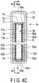
FIG. 4A is a schematic longitudinal sectional view of the battery assembly of a medical instrument unit according to a second embodiment taken along aline 4A - 4A inFIG. 4C ; -
FIG. 4B is a schematic sectional view of the battery assembly of the medical instrument unit according to the second embodiment taken along aline 4B - 4B inFIG. 4A ; -
FIG. 4C is a schematic longitudinal sectional view of the battery assembly of the medical instrument unit according to the second embodiment taken along aline 4C - 4C inFIG. 4A ; -
FIG. 5 is a schematic perspective view showing the battery assembly of a medical instrument unit according to a third embodiment; -
FIG. 6 is a schematic perspective view showing the structure of the battery of the battery assembly of a medical instrument unit according to a fourth embodiment; -
FIG. 7 is a schematic sectional view showing the battery assembly of a medical instrument unit according to a fifth embodiment; and -
FIG. 8 is a schematic longitudinal sectional view of the battery assembly of a medical instrument unit according to a sixth embodiment. - Embodiments of the present invention will now be described with reference to the accompanying drawings.
- The first embodiment will be described with reference to
FIG. 1 to FIG. 3C . - As shown in
FIG. 1 , amedical instrument unit 10 includes a medical instrumentmain body 12 and abattery assembly 14 for a medical instrument. Note that thebattery assembly 14 is used for the appropriate medical instrumentmain body 12 that performs a treatment by converting electrical energy into appropriate energy, for example, a cordless ultrasonic treatment instrument, a high-frequency treatment instrument, or an endoscope. The medical instrumentmain body 12 is not limited to a cordless instrument and may use thebattery assembly 14 as a backup power supply. - The medical instrument
main body 12 according to this embodiment includes a medical instrument housing 22, anenergy converter 24 provided in thehousing 22, and anend effector 26 provided on thehousing 22. Theenergy converter 24 may be fixed to thehousing 22 or is preferably detachable from thehousing 22. An operator can grip thehousing 22 by, for example, one hand such as the right hand and operate it. For example, when the operator operates aswitch 28 provided on thehousing 22 by the hand gripping thehousing 22, theenergy converter 24 converts electrical energy generated by thebattery assembly 14 into appropriate energy. The energy converted by theenergy converter 24 is transmitted to theend effector 26, and theend effector 26 performs an appropriate treatment. Note that theswitch 28 is electrically connected to a controller 32 (to be described later) in a state in which thebattery assembly 14 is attached to the medical instrumentmain body 12. - For example, a
slot 22a is formed in thehousing 22 of the medical instrumentmain body 12. Thebattery assembly 14 is, for example, disposed in theslot 22a of thehousing 22 and fixed or supported. A casing 34 (to be described later) of thebattery assembly 14 is preferably integrated with themedical instrument housing 22. That is, thebattery assembly 14 is preferably detachable from the medical instrumentmain body 12 or is also preferably formed to be undetachable from the medical instrumentmain body 12. - As shown in
FIG. 1 to FIG. 3C , thebattery assembly 14 includes thecontroller 32, thecasing 34, abattery 36 incorporating a first laminatedbody unit 36a (seeFIG. 2 ) of an all-solid-state battery arranged in thecasing 34, and supporters 38 (seeFIG. 3A to FIG. 3C ) that support thebattery 36 in thecasing 34. Thecasing 34 is made of, for example, a metal material or a plastic material. In the form shown inFIG. 1 , thebattery assembly 14 includes thecontroller 32. However, the medical instrumentmain body 12 may include thecontroller 32. InFIG. 1 , thecontroller 32 is disposed in thebattery assembly 14. However, thecontroller 32 is also preferably disposed in the medical instrumentmain body 12. - To the
energy converter 24 in the medical instrumentmain body 12, power is supplied from thebattery assembly 14 by appropriate electrical connection (for example, contact power supply betweencontacts battery assembly 14 is not detachable from the medical instrumentmain body 12 but fixed, theenergy converter 24 of the medical instrumentmain body 12 and thebattery assembly 14 are always electrically connected. - To the
energy converter 24 of the medical instrumentmain body 12, power is also preferably supplied from thebattery assembly 14 by non-contact power supply. When performing non-contact power supply, each of the medical instrumentmain body 12 and thebattery assembly 14 includes a known coil (not shown) that transmits/receives power. As a method of the non-contact power supply, a known electromagnetic resonance method or electromagnetic induction method can appropriately be selected and used. - Note that the
controller 32 includes a processor including a CPU or ASIC. - As shown in
FIG. 1 ,contacts FIG. 3A to FIG. 3C ) of thecontroller 32 of thebattery assembly 14 are electrically connected tocontacts main body 12, respectively. More specifically, when thebattery assembly 14 is attached to theslot 22a of the medical instrumentmain body 12, theenergy converter 24 and thecontroller 32 are electrically connected by the contact between thecontacts switch 28 and thecontroller 32 are electrically connected by the contact between thecontacts switch 28 and inputs a signal to thecontroller 32, thecontroller 32 transmits appropriate energy converted by theenergy converter 24 to theend effector 26. - At the time of charging, for example, the
controller 32 optimizes charging of thebattery 36 of thebattery assembly 14. When supplying electrical energy, thecontroller 32 appropriately controls the electrical energy (power) to be supplied to theend effector 26. - Types of the first
laminated body unit 36a used as the all-solid-state battery in thebattery 36 shown inFIG. 2 include, for example, a bulk type and a thin film type. The firstlaminated body unit 36a of thebattery 36 supported in thecasing 34 can be either of the bulk type and the thin film type of all-solid-state batteries. The firstlaminated body unit 36a of the bulk type will be exemplified here. - As shown in
FIG. 2 , the firstlaminated body unit 36a of thebattery 36 includes apositive electrode layer 52, asolid electrolyte layer 54, and anegative electrode layer 56. Each of thepositive electrode layer 52 and thenegative electrode layer 56 includes a current collector (not shown) . In the firstlaminated body unit 36a, thepositive electrode layer 52, thesolid electrolyte layer 54, and thenegative electrode layer 56 are sequentially laminated to define a lamination direction Z. The thickness of thepositive electrode layer 52, thesolid electrolyte layer 54, and thenegative electrode layer 56 in the lamination direction Z is appropriately set. In the state in which the firstlaminated body unit 36a is thus formed, thebattery 36 generates electrical energy. - As the
positive electrode layer 52, thesolid electrolyte layer 54, and thenegative electrode layer 56 of the firstlaminated body unit 36a of thebattery 36, arbitrary substances employable in the all-solid-state battery can be used. As thepositive electrode layer 52, for example, an oxide active material or a sulfide active material is usable. As thesolid electrolyte layer 54, for example, an inorganic sold electrolyte substance such as a sulfide sold electrolyte material, an oxide sold electrolyte material, or a nitride sold electrolyte material is usable. For this reason, the electrolyte of thesolid electrolyte layer 54 is not a liquid but a solid. As thenegative electrode layer 56, a material capable of occluding and emitting metal ions can be used. For example, a carbon active material or a metal active material is usable. - The
battery 36 is formed into, for example, an almost rectangular parallelepiped shape as a whole. Thebattery 36 includes a pair of first surfaces 62 (62a and 62b) having the largest surface area, and a pair of second surfaces 64 (64a and 64b) and a pair of third surfaces 66 (66a and 66b) having surface areas smaller than that of thefirst surfaces first surface 62a is the surface of thepositive electrode layer 52 including a current collector, and the otherfirst surface 62b is the surface of thenegative electrode layer 56 including a current collector. The second surfaces 64a and 64b and thethird surfaces positive electrode layer 52, thesolid electrolyte layer 54, and thenegative electrode layer 56. Note that when an XYZ orthogonal coordinate system with axes orthogonal to each other is employed, preferably, thefirst surfaces second surfaces third surfaces first surfaces second surfaces third surfaces FIG. 2 , thesecond surfaces third surfaces second surfaces third surfaces - The
battery 36 includes eightcorners 68 each formed by three surfaces. The eightcorners 68 each formed by three surfaces need not always have the surfaces intersecting at right angles and are also preferably formed as curved surfaces, as a matter of course. - Since the
battery 36 has a thin plate shape, thesolid electrolyte layer 54 of the firstlaminated body unit 36a is broken (cracked) readily not by an impact loaded to one of the second and third surfaces (end faces) 64a, 64b, 66a, and 66b but by an impact loaded to one of thefirst surfaces solid electrolyte layer 54 is broken most readily when an impact is loaded to the vicinity of the center of one of thefirst surfaces - As shown in
FIG. 3A to FIG. 3C , thecasing 34 that stores thebattery 36 is formed into, for example, a box shape, and more specifically, formed into an almost rectangular parallelepiped shape. Thecasing 34 has an internal space larger than thebattery 36 where thebattery 36 is stored. Thecasing 34 includes afirst storage portion 72 in which thecontroller 32 is stored, asecond storage portion 74 in which thebattery 36 is stored, and apartition 76 that separates thefirst storage portion 72 and thesecond storage portion 74 from each other. Thepartition 76 includesterminals contacts battery 36 to thecontroller 32. - The
second storage portion 74 of thecasing 34 includes awall section 78 configured to store thebattery 36 inside. Thewall section 78 includes first inner surfaces 82 (82a and 82b) that face each other and also face the pair of first surfaces 62 in a state in which thebattery 36 is stored in thesecond storage portion 74, second inner surfaces 84 (84a and 84b) that face each other and face the pair of second surfaces 64, and third inner surfaces 86 (86a and 86b) that face each other and face the pair of third surfaces 66. Note that thecasing 34 includes firstouter surfaces inner surfaces outer surface 94b on the back side of the secondinner surface 84b, and thirdouter surfaces inner surfaces position 94a inFIG. 3A andFIG. 3C corresponds to the second outer surface. The above-describedcontacts FIG. 1 ) of thebattery 36 are disposed on the secondouter surface 94a. - The
supporters 38 that support thebattery 36 are disposed in thesecond storage portion 74 of thecasing 34. Thesupporters 38 are preferably made of, for example, an elastic material including a resin material such as a rubber material and so on capable of flexibly bending, a porous material such as foamed styrol and so on, or a gel material and so on having shock absorbency, or an elastic material such as a coil spring (not shown), a rubber material and so on that appropriately adjusts the distance from thewall section 78 of thecasing 34 by elastic deformation. Note that thesupporters 38 preferably have electrical insulating properties. In addition, thesupporters 38 preferably have a proper heat resistance. - In this embodiment, the
supporters 38 are fixed to or supported by eightcorners 88 of thewall section 78. Thesupporters 38 need not always be arranged at all the eightcorners 88. Onesupporter 38 may suffice if thesupporter 38 can support thebattery 36. That is, thesupporters 38 need only support one of the eightcorners 68 of thebattery 36. - Here, the
supporters 38 are each assumed to support the three surfaces of a corresponding one of the eightcorners 68 of thebattery 36. One of the eightsupporters 38 supports, for example, thefirst surface 62a, thesecond surface 64b, and thethird surface 66b at the upper right corner inFIG. 2 . - The
supporters 38 support thebattery 36 apart from the wall section (inner surface) 78 of thecasing 34. Hence, a gap (space) G is formed between thewall section 78 of thecasing 34 and the outer surface of thebattery 36. For this reason, in a state in which thebattery 36 is stored in thesecond storage portion 74 of thecasing 34, onefirst surface 62a of thebattery 36 is located at a position close to one firstinner surface 82a but faces the firstinner surface 82a while being spaced apart by the appropriate gap G, and the other firstinner surface 82b faces the otherfirst surface 62b of thebattery 36 closely while being spaced apart by the appropriate gap G. In addition, one secondinner surface 84a faces onesecond surface 64a of thebattery 36 closely while being spaced apart by the appropriate gap G, and the other secondinner surface 84b faces the othersecond surface 64b of thebattery 36 closely while being spaced apart by the appropriate gap G. One thirdinner surface 86a faces onethird surface 66a of thebattery 36 closely while being spaced apart by the appropriate gap G, and the other thirdinner surface 86b faces the otherthird surface 66b of thebattery 36 closely while being spaced apart by the appropriate gap G. - Each
supporter 38 is preferably formed as small as possible and supports acorresponding corner 68 of thebattery 36 at three points in an almost floating state. In this case, for example, thesupporter 38 at the upper right corner inFIG. 2 has a small contact area to thefirst surface 62a, thesecond surface 64b, and thethird surface 66b. - If the
battery assembly 14 is dropped, and an impact is loaded to thecasing 34, the impact is transmitted from thecasing 34 to thebattery 36 via thesupporters 38. At this time, the gap G is formed between thecasing 34 and thebattery 36. In addition, the contact area between thesupporters 38 and thebattery 36 is small, and the impact is hardly transmitted to thesolid electrolyte layer 54. - The
supporters 38 are made of, for example, an elastically deformable material, or support thebattery 36 via an elastically deformable material. For this reason, the impact loaded to thebattery assembly 14 is largely attenuated by thesupporters 38. Hence, the impact loaded to thebattery assembly 14 is not directly transmitted from thecasing 34 to thebattery 36 but transmitted in an attenuated state. - The
supporters 38 preferably support thebattery 36 at, for example, all the corners (eight corners) 68 in an almost floating state with an appropriate play. In this state, when the impact loaded to thecasing 34 is transmitted to thebattery 36 via thesupporters 38, thesupporters 38 buffer the impact loaded to thebattery assembly 14 by the play in cooperation with the gap G. For this reason, when the impact loaded to thebattery assembly 14 is transmitted to thebattery 36 via thecasing 34, the impact is transmitted in a largely attenuated state. That is, transmission of a large impact to thebattery 36 is prevented or suppressed. - For example, when the
battery assembly 14 is dropped on a worktable, an external force can be loaded to one of the pair of firstouter surfaces casing 34 by a projection or the like. When the impact is loaded to the firstouter surface 92a, the impact is transmitted to the firstinner surface 82a. Since the gap G is formed between the firstinner surface 82a and thefirst surface 62a of thebattery 36, the firstinner surface 82a of thecasing 34 is prevented from directly pressing thefirst surface 62a of thebattery 36. - Similarly, even if an impact is loaded to the second
outer surface 94a, the secondinner surface 84a of thecasing 34 is prevented from directly pressing thesecond surface 64a of thebattery 36 because the gap G is formed between the secondinner surface 84a and thesecond surface 64a of thebattery 36. Additionally, even if an impact is loaded to the thirdouter surface 96a, the thirdinner surface 86a of thecasing 34 is prevented from directly pressing thethird surface 66a of thebattery 36 because the gap G is formed between the thirdinner surface 86a and the third surface. 66a of thebattery 36. - As shown in
FIG. 1 , thebattery assembly 14 is attached to thehousing 22 of the medical instrumentmain body 12 and forms themedical instrument unit 10. Even if themedical instrument unit 10 is dropped on, for example, a worktable (not shown), when the impact loaded to thehousing 22 is transmitted via thecasing 34 and thesupporters 38, thesupporters 38 buffer the impact loaded to thecasing 34 in cooperation with the gap G. For this reason, when the impact loaded to thecasing 34 is transmitted to thebattery 36, it is transmitted in a largely attenuated state. That is, transmission of a large impact to thebattery 36 is prevented or suppressed. - As described above, according to this embodiment, the followings are possible.
- The
battery 36 including the firstlaminated body unit 36a is supported in thecasing 34 by thesupporters 38 made of an elastically deformable material or including an elastically deformable material. The gap G is formed between thebattery 36 and thewall section 78 of thecasing 34. For this reason, an impact loaded to thebattery assembly 14 can be prevented from being transmitted from thecasing 34 to thebattery 36 via thesupporters 38. Hence, thebattery assembly 14 according to this embodiment can prevent damage to thebattery 36 including thesolid electrolyte layer 54 as much as possible when, for example, thebattery assembly 14 is dropped on a worktable, and an impact is loaded. - In particular, the gap G exists between the
first surfaces battery 36 and the firstinner surfaces wall section 78 of thecasing 34. For this reason, an impact loaded to the firstouter surfaces casing 34 can be prevented from being transmitted to one of thefirst surfaces - It is therefore possible to provide the
battery assembly 14 for a medical instrument and themedical instrument unit 10 capable of suppressing transmission of an impact to the first laminated body unit (all-solid-state battery) 36a and occurrence of damage such as a crack even if an impact is applied to thecasing 34. - Note that the first
laminated body unit 36a itself also has appropriate shock resistance. Even if an impact is applied to thecasing 34, and the impact is transmitted to the first laminated body unit (all-solid-state battery) 36a, the shock resistance can prevent damage to the firstlaminated body unit 36a. - The second embodiment will be described next with reference to
FIG. 4A to FIG. 4C . This embodiment is a modification the first embodiment. The same reference numerals as in the first embodiment are added to the same members as much as possible, and a detailed description thereof will be omitted. - As shown in
FIG. 4A to FIG. 4C ,supporters 138 according to this embodiment almost wholly support, for example,edge portions first surfaces third surfaces supporters 138 support the vicinities of the ends of thefirst surfaces second surfaces supporters 38, thesupporters 138 are preferably made of an elastic material including a resin material such as a rubber material and so on capable of flexibly bending, or a gel material and so on, or an elastic material such as a coil spring (not shown), a rubber material and so on that appropriately adjusts the distance from awall section 78 of acasing 34 by elastic deformation. In addition, gaps G are formed between thesupporters 138 and firstinner surfaces wall section 78 of thecasing 34 such that when an external force is applied to thewall section 78, and the firstinner surfaces inner surfaces supporters 138. - The gaps G are formed between the first
inner surfaces wall section 78 and thefirst surfaces battery 36. When an impact is loaded to abattery assembly 14, the impact is transmitted from thecasing 34 to thebattery 36 via thesupporters 138. At this time, since the gaps G are formed between the firstinner surfaces wall section 78 of thecasing 34 and thefirst surfaces battery 36, the impact is hardly transmitted to thefirst surfaces - When an impact is loaded to the first
outer surface 92a, the impact is transmitted to the firstinner surface 82a. Since the gap G is formed between the firstinner surface 82a and thefirst surface 62a of thebattery 36, the firstinner surface 82a of thecasing 34 is prevented from directly pressing thefirst surface 62a of thebattery 36. - The gaps G are formed between second
inner surfaces wall section 78 and thesecond surfaces battery 36. For this reason, even if an impact is loaded to a secondouter surface 94a, the secondinner surface 84a of thecasing 34 is prevented from directly pressing thesecond surface 64a of thebattery 36. In addition, the gaps G are formed between thirdinner surfaces wall section 78 andthird surfaces battery 36. For this reason, even if an impact is loaded to a thirdouter surface 96a, the thirdinner surface 86a of thecasing 34 is prevented from directly pressing thethird surface 66a of thebattery 36. - The third embodiment will be described next with reference to
FIG. 5 . This embodiment is a modification the first and second embodiments. The same reference numerals as in the first and second embodiments are added to the same members as much as possible, and a detailed description thereof will be omitted. - As shown in
FIG. 5 , asupporter 238 according to this embodiment almost wholly supports, for example, anedge portion 62e offirst surfaces second surfaces supporter 238 may support onecorner 68 or may support theedge portion 62e at a plurality of points. In addition, gaps G are formed between thesupporter 238 and firstinner surfaces wall section 78 of acasing 34 such that when an external force is applied to thewall section 78, and the firstinner surfaces inner surfaces supporter 238. - The gaps G are formed between the first
inner surfaces wall section 78 and thefirst surfaces battery assembly 14, the impact is transmitted from thecasing 34 to abattery 36 via thesupporter 238. At this time, since the gap G is formed between thecasing 34 and thebattery 36, the impact is hardly transmitted to asolid electrolyte layer 54. - Note that in this embodiment as well, the gap G is preferably formed between the
supporter 238 and thesecond surface 64a, like the gap G shown inFIG. 4B . - The fourth embodiment will be described next with reference to
FIG. 6 . This embodiment is a modification the first to third embodiments. The same reference numerals as in the first to third embodiments are added to the same members as much as possible, and a detailed description thereof will be omitted. - As shown in
FIG. 6 , abattery 36 of abattery assembly 14 for a medical instrument includes a secondlaminated body unit 36b of an all-solid-state battery arranged in acasing 34 in addition to a firstlaminated body unit 36a. - In the second
laminated body unit 36b, apositive electrode layer 52, asolid electrolyte layer 54, and anegative electrode layer 56 are sequentially laminated along a lamination direction Z, in addition to the firstlaminated body unit 36a. - A terminal (not shown) of the
positive electrode layer 52 of the firstlaminated body unit 36a of thebattery 36 according to this embodiment is connected to a terminal (not shown) of thenegative electrode layer 56 of the secondlaminated body unit 36b adjacent to the firstlaminated body unit 36a. In thebattery assembly 14 according to this embodiment, the plurality oflaminated body units -
Supporters 38 of thecasing 34 support thebattery 36 including the firstlaminated body unit 36a and the secondlaminated body unit 36b. Thesupporters 38 support thebattery 36 including the firstlaminated body unit 36a and the secondlaminated body unit 36b apart from awall section 78 of thecasing 34. That is, gaps G are formed between the firstlaminated body unit 36a and thewall section 78 of thecasing 34 and between the secondlaminated body unit 36b and thewall section 78 of thecasing 34. Hence, thesupporters 38 support thebattery 36 apart from thewall section 78 in the lamination direction Z. - Note that in addition to a case in which only the first
laminated body unit 36a is provided and a case in which the firstlaminated body unit 36a and the secondlaminated body unit 36b are provided, thebattery 36 also preferably further includes a laminated body unit, as a matter of course. That is, thebattery 36 preferably includes only onelaminated body unit 36a and also preferably includes a plurality oflaminated body units - That is, in the first to third embodiments, the description has been made assuming that each of the
positive electrode layer 52, thesolid electrolyte layer 54, and thenegative electrode layer 56 of thebattery 36 includes one layer for the descriptive convenience. As shown inFIG. 6 , a plurality of layers are preferably formed in the order of thepositive electrode layer 52, thesolid electrolyte layer 54, thenegative electrode layer 56, thepositive electrode layer 52, thesolid electrolyte layer 54, and thenegative electrode layer 56, as a matter of course. That is, a plurality of sets each including thepositive electrode layer 52, thesolid electrolyte layer 54, thenegative electrode layer 56 are also preferably adjacently stored in onecasing 34. That is, to increase the battery capacity, thebattery 36 in thecasing 34 preferably includes a plurality of laminated body units laminated. However, if an appropriate capacity can be ensured, one laminated body unit may suffice. - The fifth embodiment will be described next with reference to
FIG. 7 . This embodiment is a modification the first to fourth embodiments. The same reference numerals as in the first to fourth embodiments are added to the same members as much as possible, and a detailed description thereof will be omitted. - As shown in
FIG. 7 , a thin film type battery is also preferably used as the all-solid-state battery of abattery 36. Thebattery 36 according to this embodiment includes asubstrate 58. That is, thebattery 36 includes thesubstrate 58 that supports at least one of apositive electrode layer 52 and anegative electrode layer 56. Here, a firstlaminated body unit 36a includes thesubstrate 58 in addition to thepositive electrode layer 52, asolid electrolyte layer 54, and thenegative electrode layer 56. Note that a secondlaminated body unit 36b includes thepositive electrode layer 52, thesolid electrolyte layer 54, and thenegative electrode layer 56. That is, thesubstrate 58 is commonly used for the firstlaminated body unit 36a and the secondlaminated body unit 36b. Thesubstrate 58 is preferably formed to have the function of acontroller 32 described above. That is, as shown inFIG. 7 , abattery assembly 14 does not always need thecontroller 32. This also applies to the other embodiments. - The
laminated body unit 36a including thesubstrate 58 is also supported by at least one ofsupporters laminated body unit 36a of thebattery 36 described in the first to fourth embodiments. An example in which thesupporter 238 is used will be described here as a modification of the fourth embodiment. However, thesupporters - Note that as shown in
FIG. 7 , thesubstrate 58 is preferably formed to be larger than afirst surface 62a of the secondlaminated body unit 36b (thefirst surface 62a of the battery 36). - The
supporter 238 supports anedge portion 58a of thesubstrate 58 apart from firstinner surfaces wall section 78 of acasing 34 in a lamination direction Z. At this time, gaps G are formed between thefirst surface 62a of thebattery 36 and the firstinner surface 82a, betweensecond surfaces inner surfaces third surfaces inner surfaces solid electrolyte layer 54 of thebattery 36 from being broken by an impact to thecasing 34 as much as possible, as described in the first to fourth embodiments. In addition, thesupporter 238 is provided apart from the firstinner surfaces wall section 78 of thecasing 34 at the gap G such that when an external force is applied to thewall section 78, and the firstinner surfaces inner surfaces supporters 238 . - The sixth embodiment will be described next with reference to
FIG. 8 . This embodiment is a modification the first to fifth embodiments. The same reference numerals as in the first to fifth embodiments are added to the same members as much as possible, and a detailed description thereof will be omitted. This embodiment will be described here as a modification of the first embodiment. However, in the second to fifth embodiments as well, a buffer B to be described later can appropriately be arranged in place of the gap G. - In this embodiment, the buffer B made of a gel substance or a porous material such as foamed styrol is arranged in place of the gap G described in the first to fifth embodiments. The buffer B need not always fill the entire gap G and may be arranged only partially. The buffer B preferably has electrical insulating properties. In addition, the buffer B preferably has a proper heat resistance.
- When an impact is loaded to a
casing 34, the buffer B prevents, from the inner surface of thecasing 34, the impact from being transmitted to abattery 36, as in a case in which the gap G is formed. In addition, since the buffer B is provided between thebattery 36 and awall section 78, the vibration of thebattery 36 caused by the impact to thecasing 34 can be attenuated earlier than in the case in which the gap G is formed. - Although the several embodiments have been specifically explained with reference to the drawings, the present invention is not restricted to the foregoing embodiments, and it includes all embodiments effected without departing from the gist thereof.
Claims (9)
- A battery assembly for a medical instrument that an operator can grip by a hand and operate, comprising:a battery including a first laminated body unit including a positive electrode layer, a solid electrolyte layer, and a negative electrode layer laminated sequentially to define a lamination direction and configured to generate electrical energy;a casing including a wall section configured to store the battery inside; anda support provided in the casing and configured to support the battery apart from the wall section in the lamination direction.
- The battery assembly for the medical instrument according to claim 1, wherein the battery includes a second laminated body unit stored in the casing to face the first laminated body unit, including a positive electrode layer, a solid electrolyte layer, and a negative electrode layer laminated along the lamination direction, and configured to generate electrical energy.
- The battery assembly for the medical instrument according to claim 1, wherein:the battery includes a plurality of corners, andthe support is configured to support at least one of the plurality of corners of the battery.
- The battery assembly for the medical instrument according to claim 1, wherein:the battery includes an edge portion, andthe support is configured to support the edge portion of the battery.
- The battery assembly for the medical instrument according to claim 1, wherein:the battery includes a substrate configured to hold at least one of the positive electrode layer, the solid electrolyte layer, and the negative electrode layer, andthe support is configured to support a part of the substrate apart from the wall section in the lamination direction.
- The battery assembly for the medical instrument according to claim 1, comprising a buffer provided between the battery and the wall section and configured to buffer an impact from the wall section to the battery.
- A medical instrument unit comprising:a medical instrument housing that an operator grips by a hand; anda battery assembly for the medical instrument of claim 1 attached to the medical instrument housing.
- The medical instrument unit according to claim 7, wherein the casing is integrated with the medical instrument housing.
- The medical instrument unit according to claim 7, comprising an end effector provided on the medical instrument housing and configured to perform a treatment using the electrical energy of the battery.
Applications Claiming Priority (2)
| Application Number | Priority Date | Filing Date | Title |
|---|---|---|---|
| JP2015097393 | 2015-05-12 | ||
| PCT/JP2016/063768 WO2016181938A1 (en) | 2015-05-12 | 2016-05-09 | Medical device battery assembly and medical device unit |
Publications (2)
| Publication Number | Publication Date |
|---|---|
| EP3297058A1 true EP3297058A1 (en) | 2018-03-21 |
| EP3297058A4 EP3297058A4 (en) | 2019-01-16 |
Family
ID=57247977
Family Applications (1)
| Application Number | Title | Priority Date | Filing Date |
|---|---|---|---|
| EP16792663.3A Withdrawn EP3297058A4 (en) | 2015-05-12 | 2016-05-09 | Medical device battery assembly and medical device unit |
Country Status (5)
| Country | Link |
|---|---|
| US (1) | US10290843B2 (en) |
| EP (1) | EP3297058A4 (en) |
| JP (1) | JP6129441B2 (en) |
| CN (1) | CN107112470B (en) |
| WO (1) | WO2016181938A1 (en) |
Cited By (1)
| Publication number | Priority date | Publication date | Assignee | Title |
|---|---|---|---|---|
| EP4099485A4 (en) * | 2020-01-29 | 2024-01-17 | Panasonic Intellectual Property Management Co., Ltd. | BATTERY PACK AND POWER TOOL |
Families Citing this family (5)
| Publication number | Priority date | Publication date | Assignee | Title |
|---|---|---|---|---|
| JP7016779B2 (en) * | 2018-09-20 | 2022-02-07 | 積水化学工業株式会社 | Plasma treatment device |
| CN209487571U (en) * | 2019-03-14 | 2019-10-11 | 宁德新能源科技有限公司 | Electrochemical energy storage device |
| CN113678310B (en) * | 2019-03-29 | 2024-03-26 | 株式会社村田制作所 | Battery pack |
| CN110974329A (en) * | 2019-11-13 | 2020-04-10 | 北京派尔特医疗科技股份有限公司 | Stapler and timing discharge method thereof |
| CN121058112A (en) * | 2023-05-18 | 2025-12-02 | 麦克赛尔株式会社 | Solid electrolyte batteries and their manufacturing methods |
Family Cites Families (19)
| Publication number | Priority date | Publication date | Assignee | Title |
|---|---|---|---|---|
| JP3402002B2 (en) * | 1995-07-17 | 2003-04-28 | 松下電器産業株式会社 | All-solid lithium battery |
| JP2000271143A (en) * | 1999-03-25 | 2000-10-03 | Olympus Optical Co Ltd | Battery operated surgical device |
| JP4661020B2 (en) * | 2002-10-16 | 2011-03-30 | 日産自動車株式会社 | Bipolar lithium ion secondary battery |
| JP4857896B2 (en) * | 2006-05-11 | 2012-01-18 | トヨタ自動車株式会社 | Battery pack and vehicle |
| US20080057390A1 (en) | 2006-08-31 | 2008-03-06 | Seiko Epson Corporation | Secondary battery |
| JP4741559B2 (en) * | 2006-08-31 | 2011-08-03 | 株式会社国際基盤材料研究所 | Secondary battery and secondary battery unit |
| US8039010B2 (en) * | 2006-11-03 | 2011-10-18 | Allergan, Inc. | Sustained release intraocular drug delivery systems comprising a water soluble therapeutic agent and a release modifier |
| JP2010118159A (en) * | 2008-11-11 | 2010-05-27 | Sumitomo Electric Ind Ltd | Solid-state battery, and method of manufacturing solid-state battery |
| JP2013126430A (en) * | 2010-08-25 | 2013-06-27 | Kevin W Smith | Battery-powered hand-held ultrasonic surgical cautery cutting device |
| CN103262330A (en) * | 2010-12-15 | 2013-08-21 | 株式会社村田制作所 | Solid battery |
| JP5904125B2 (en) * | 2011-01-21 | 2016-04-13 | 日本ゼオン株式会社 | Method for producing electrode for electrochemical device and electrochemical device |
| CN103533881A (en) * | 2011-03-17 | 2014-01-22 | 基文影像公司 | Reusable in-vivo device, system and method of assembly thereof |
| KR101319523B1 (en) * | 2011-12-19 | 2013-11-06 | 지에스나노텍 주식회사 | Thin film cells module and thin film cells package and apparatus for packaging thin film cells and method for manufacturing thin film cells package |
| US9326812B2 (en) * | 2012-01-25 | 2016-05-03 | Covidien Lp | Portable surgical instrument |
| KR102039034B1 (en) * | 2012-03-26 | 2019-10-31 | 제온 코포레이션 | Composite particles for negative electrodes of secondary batteries, use of same, method for producing same, and binder composition |
| JP6090895B2 (en) * | 2012-04-26 | 2017-03-08 | 国立研究開発法人産業技術総合研究所 | All-solid-state lithium secondary battery using sulfur-based cathode material |
| US9520618B2 (en) * | 2013-02-12 | 2016-12-13 | Ambri Inc. | Electrochemical energy storage devices |
| US20140207124A1 (en) * | 2013-01-23 | 2014-07-24 | Ethicon Endo-Surgery, Inc. | Surgical instrument with selectable integral or external power source |
| JP6386224B2 (en) * | 2013-12-06 | 2018-09-05 | 株式会社オハラ | All solid battery |
-
2016
- 2016-05-09 CN CN201680005616.5A patent/CN107112470B/en active Active
- 2016-05-09 WO PCT/JP2016/063768 patent/WO2016181938A1/en not_active Ceased
- 2016-05-09 JP JP2016567278A patent/JP6129441B2/en active Active
- 2016-05-09 EP EP16792663.3A patent/EP3297058A4/en not_active Withdrawn
-
2017
- 2017-08-02 US US15/666,766 patent/US10290843B2/en active Active
Cited By (1)
| Publication number | Priority date | Publication date | Assignee | Title |
|---|---|---|---|---|
| EP4099485A4 (en) * | 2020-01-29 | 2024-01-17 | Panasonic Intellectual Property Management Co., Ltd. | BATTERY PACK AND POWER TOOL |
Also Published As
| Publication number | Publication date |
|---|---|
| US10290843B2 (en) | 2019-05-14 |
| US20170331084A1 (en) | 2017-11-16 |
| JPWO2016181938A1 (en) | 2017-06-01 |
| WO2016181938A1 (en) | 2016-11-17 |
| CN107112470A (en) | 2017-08-29 |
| JP6129441B2 (en) | 2017-05-17 |
| EP3297058A4 (en) | 2019-01-16 |
| CN107112470B (en) | 2020-04-03 |
Similar Documents
| Publication | Publication Date | Title |
|---|---|---|
| US10290843B2 (en) | Battery assembly for medical instrument and medical instrument unit | |
| CN102683633B (en) | Set of cells | |
| CN110998902B (en) | Battery module and method of manufacturing the same | |
| US20210013471A1 (en) | Partition member and assembled battery | |
| JP5240817B2 (en) | Lithium ion secondary battery | |
| JP6730016B2 (en) | Electrochemical element and card equipped with the same | |
| JP2012059361A (en) | Battery | |
| CN106415877A (en) | Secondary battery and electronic device | |
| CN115275092A (en) | Electrode assembly, battery monomer, battery and consumer | |
| CN107887540B (en) | Battery | |
| KR102266593B1 (en) | Rechargeable battery | |
| WO2019184492A1 (en) | Battery sampling assembly and battery box | |
| JP7121905B2 (en) | sealed battery | |
| JP7253743B2 (en) | battery stack | |
| KR101577186B1 (en) | Battery Cell Having Position-changeable Electrode Lead | |
| JP2020087873A (en) | Battery pack | |
| US20230216130A1 (en) | Secondary battery module and method for manufacturing the same | |
| JP2010205672A (en) | Battery pack | |
| JP7173855B2 (en) | Electrode encapsulation and power storage device | |
| CN218827586U (en) | Battery insulating support and battery device | |
| KR20190056170A (en) | Battery Pack Comprising coverlay | |
| CN107078241A (en) | Medical battery | |
| US20250055139A1 (en) | Battery module | |
| JPWO2016075819A1 (en) | Battery and battery system | |
| WO2022201672A1 (en) | Accommodating case, and method for accommodating battery pack in said accommodating case |
Legal Events
| Date | Code | Title | Description |
|---|---|---|---|
| STAA | Information on the status of an ep patent application or granted ep patent |
Free format text: STATUS: THE INTERNATIONAL PUBLICATION HAS BEEN MADE |
|
| PUAI | Public reference made under article 153(3) epc to a published international application that has entered the european phase |
Free format text: ORIGINAL CODE: 0009012 |
|
| STAA | Information on the status of an ep patent application or granted ep patent |
Free format text: STATUS: REQUEST FOR EXAMINATION WAS MADE |
|
| 17P | Request for examination filed |
Effective date: 20171207 |
|
| AK | Designated contracting states |
Kind code of ref document: A1 Designated state(s): AL AT BE BG CH CY CZ DE DK EE ES FI FR GB GR HR HU IE IS IT LI LT LU LV MC MK MT NL NO PL PT RO RS SE SI SK SM TR |
|
| AX | Request for extension of the european patent |
Extension state: BA ME |
|
| DAV | Request for validation of the european patent (deleted) | ||
| DAX | Request for extension of the european patent (deleted) | ||
| RIC1 | Information provided on ipc code assigned before grant |
Ipc: A61B 17/00 20060101ALI20181206BHEP Ipc: A61B 17/32 20060101ALI20181206BHEP Ipc: A61B 18/12 20060101ALI20181206BHEP Ipc: H01M 2/10 20060101AFI20181206BHEP Ipc: A61B 18/10 20060101ALI20181206BHEP Ipc: H01M 10/0562 20100101ALI20181206BHEP Ipc: H01M 10/05 20100101ALI20181206BHEP Ipc: H01M 2/02 20060101ALI20181206BHEP |
|
| A4 | Supplementary search report drawn up and despatched |
Effective date: 20181213 |
|
| STAA | Information on the status of an ep patent application or granted ep patent |
Free format text: STATUS: THE APPLICATION IS DEEMED TO BE WITHDRAWN |
|
| 18D | Application deemed to be withdrawn |
Effective date: 20190719 |