EP3297012A1 - Push switch - Google Patents
Push switch Download PDFInfo
- Publication number
- EP3297012A1 EP3297012A1 EP16792554.4A EP16792554A EP3297012A1 EP 3297012 A1 EP3297012 A1 EP 3297012A1 EP 16792554 A EP16792554 A EP 16792554A EP 3297012 A1 EP3297012 A1 EP 3297012A1
- Authority
- EP
- European Patent Office
- Prior art keywords
- contact
- dome
- push switch
- movable contact
- fixed contact
- Prior art date
- Legal status (The legal status is an assumption and is not a legal conclusion. Google has not performed a legal analysis and makes no representation as to the accuracy of the status listed.)
- Withdrawn
Links
- 230000003247 decreasing effect Effects 0.000 claims abstract description 8
- 230000007423 decrease Effects 0.000 claims abstract description 7
- 230000000052 comparative effect Effects 0.000 description 8
- 230000005489 elastic deformation Effects 0.000 description 5
- 239000002184 metal Substances 0.000 description 4
- 230000000694 effects Effects 0.000 description 3
- 238000003754 machining Methods 0.000 description 3
- 229920003002 synthetic resin Polymers 0.000 description 3
- 239000000057 synthetic resin Substances 0.000 description 3
- 238000001746 injection moulding Methods 0.000 description 2
- 238000004519 manufacturing process Methods 0.000 description 1
- 238000012986 modification Methods 0.000 description 1
- 230000004048 modification Effects 0.000 description 1
Images




Classifications
-
- H—ELECTRICITY
- H01—ELECTRIC ELEMENTS
- H01H—ELECTRIC SWITCHES; RELAYS; SELECTORS; EMERGENCY PROTECTIVE DEVICES
- H01H13/00—Switches having rectilinearly-movable operating part or parts adapted for pushing or pulling in one direction only, e.g. push-button switch
- H01H13/02—Details
- H01H13/26—Snap-action arrangements depending upon deformation of elastic members
- H01H13/48—Snap-action arrangements depending upon deformation of elastic members using buckling of disc springs
-
- H—ELECTRICITY
- H01—ELECTRIC ELEMENTS
- H01H—ELECTRIC SWITCHES; RELAYS; SELECTORS; EMERGENCY PROTECTIVE DEVICES
- H01H13/00—Switches having rectilinearly-movable operating part or parts adapted for pushing or pulling in one direction only, e.g. push-button switch
- H01H13/02—Details
- H01H13/12—Movable parts; Contacts mounted thereon
- H01H13/14—Operating parts, e.g. push-button
-
- H—ELECTRICITY
- H01—ELECTRIC ELEMENTS
- H01H—ELECTRIC SWITCHES; RELAYS; SELECTORS; EMERGENCY PROTECTIVE DEVICES
- H01H13/00—Switches having rectilinearly-movable operating part or parts adapted for pushing or pulling in one direction only, e.g. push-button switch
- H01H13/02—Details
- H01H13/12—Movable parts; Contacts mounted thereon
- H01H13/20—Driving mechanisms
-
- H—ELECTRICITY
- H01—ELECTRIC ELEMENTS
- H01H—ELECTRIC SWITCHES; RELAYS; SELECTORS; EMERGENCY PROTECTIVE DEVICES
- H01H13/00—Switches having rectilinearly-movable operating part or parts adapted for pushing or pulling in one direction only, e.g. push-button switch
- H01H13/70—Switches having rectilinearly-movable operating part or parts adapted for pushing or pulling in one direction only, e.g. push-button switch having a plurality of operating members associated with different sets of contacts, e.g. keyboard
- H01H13/7006—Switches having rectilinearly-movable operating part or parts adapted for pushing or pulling in one direction only, e.g. push-button switch having a plurality of operating members associated with different sets of contacts, e.g. keyboard comprising a separate movable contact element for each switch site, all other elements being integrated in layers
-
- H—ELECTRICITY
- H01—ELECTRIC ELEMENTS
- H01H—ELECTRIC SWITCHES; RELAYS; SELECTORS; EMERGENCY PROTECTIVE DEVICES
- H01H13/00—Switches having rectilinearly-movable operating part or parts adapted for pushing or pulling in one direction only, e.g. push-button switch
- H01H13/70—Switches having rectilinearly-movable operating part or parts adapted for pushing or pulling in one direction only, e.g. push-button switch having a plurality of operating members associated with different sets of contacts, e.g. keyboard
- H01H13/84—Switches having rectilinearly-movable operating part or parts adapted for pushing or pulling in one direction only, e.g. push-button switch having a plurality of operating members associated with different sets of contacts, e.g. keyboard characterised by ergonomic functions, e.g. for miniature keyboards; characterised by operational sensory functions, e.g. sound feedback
- H01H13/85—Switches having rectilinearly-movable operating part or parts adapted for pushing or pulling in one direction only, e.g. push-button switch having a plurality of operating members associated with different sets of contacts, e.g. keyboard characterised by ergonomic functions, e.g. for miniature keyboards; characterised by operational sensory functions, e.g. sound feedback characterised by tactile feedback features
-
- H—ELECTRICITY
- H01—ELECTRIC ELEMENTS
- H01H—ELECTRIC SWITCHES; RELAYS; SELECTORS; EMERGENCY PROTECTIVE DEVICES
- H01H2215/00—Tactile feedback
- H01H2215/004—Collapsible dome or bubble
-
- H—ELECTRICITY
- H01—ELECTRIC ELEMENTS
- H01H—ELECTRIC SWITCHES; RELAYS; SELECTORS; EMERGENCY PROTECTIVE DEVICES
- H01H2215/00—Tactile feedback
- H01H2215/004—Collapsible dome or bubble
- H01H2215/012—Positioning of individual dome
-
- H—ELECTRICITY
- H01—ELECTRIC ELEMENTS
- H01H—ELECTRIC SWITCHES; RELAYS; SELECTORS; EMERGENCY PROTECTIVE DEVICES
- H01H2215/00—Tactile feedback
- H01H2215/004—Collapsible dome or bubble
- H01H2215/018—Collapsible dome or bubble unstressed in open position of switch
-
- H—ELECTRICITY
- H01—ELECTRIC ELEMENTS
- H01H—ELECTRIC SWITCHES; RELAYS; SELECTORS; EMERGENCY PROTECTIVE DEVICES
- H01H2215/00—Tactile feedback
- H01H2215/004—Collapsible dome or bubble
- H01H2215/022—Asymmetric; Elliptic; Square
-
- H—ELECTRICITY
- H01—ELECTRIC ELEMENTS
- H01H—ELECTRIC SWITCHES; RELAYS; SELECTORS; EMERGENCY PROTECTIVE DEVICES
- H01H2215/00—Tactile feedback
- H01H2215/028—Tactile feedback alterable
-
- H—ELECTRICITY
- H01—ELECTRIC ELEMENTS
- H01H—ELECTRIC SWITCHES; RELAYS; SELECTORS; EMERGENCY PROTECTIVE DEVICES
- H01H2227/00—Dimensions; Characteristics
- H01H2227/026—Separate dome contact
- H01H2227/0261—Separate dome contact with an aperture in contact making centre of dome
-
- H—ELECTRICITY
- H01—ELECTRIC ELEMENTS
- H01H—ELECTRIC SWITCHES; RELAYS; SELECTORS; EMERGENCY PROTECTIVE DEVICES
- H01H2227/00—Dimensions; Characteristics
- H01H2227/032—Operating force
- H01H2227/034—Regulation of operating force
-
- H—ELECTRICITY
- H01—ELECTRIC ELEMENTS
- H01H—ELECTRIC SWITCHES; RELAYS; SELECTORS; EMERGENCY PROTECTIVE DEVICES
- H01H2233/00—Key modules
- H01H2233/07—Cap or button on actuator part
Definitions
- the present invention relates to a push switch having a click feel.
- Patent Document 1 discloses a push switch having a click feel.
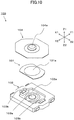
- FIG. 10 is an exploded perspective view of a push switch 100 disclosed in Patent Document 1.
- FIGs. 11 (a) and 11(b) are cross-sectional views of the related-art push switch 100.
- FIG. 11 (a) is a cross-sectional view illustrating an initial state where the push switch 100 is not being pressed.
- FIG. 11 (b) is a cross-sectional view illustrating a state where the push switch 100 is being pressed.
- the push switch 100 includes a movable contact 101 including a round part 101a having a dome shape, a housing 102 including a recess 102a for housing the movable contact 101 and a fixed contact 103 to be brought into contact with the movable contact 101, and a sheet 104 including a pressed part 104a that covers the recess 102a of the housing 102 and is pressed from the outside.
- the round part 101a of the movable contact 101 is not inverted in shape, and a first fixed contact 103a and second fixed contacts 103b are not electrically connected to each other.
- the round part 101a of the movable contact 101 is pressed via the sheet 104 as illustrated in FIG. 11 (b) .
- the pressed round part 101a sags in the Z2 direction and is inverted in shape, and contacts the first fixed contact 103a.
- the push switch 100 is configured such that the round part 101a collides with the fixed contact 103 before the round part 101a is completely inverted.
- Patent Document 1 Japanese Laid-Open Patent Publication No. 2014-13672
- a push switch such as the push switch 100 having a click feel has a problem where a sound is generated when the push switch is turned on.
- the main causes of the operation sound generated when the push switch is turned on are supposed to be a collision sound that is generated when the round part 101a of the movable contact 101 collides with the first fixed contact 103a and the vibration of the round part 101a. Accordingly, the operation sound increases as the force of inversion of the round part 101a increases.
- the operation sound increases as the click feel is made clearer, and it is difficult to provide a switch with a small operation sound.
- One object of the present invention is to solve the above problem and to provide a push switch with a good click feel as well as a small operation sound.
- a push switch of the present invention includes a movable contact including a dome part that is shaped like a dome and configured to be inverted in shape when pressed, and a fixed contact including a first fixed contact, the movable contact being configured to be brought into contact with and away from the first fixed contact.
- the push switch is configured such that an operating load necessary to press the movable contact gradually increases after the movable contact starts to be pressed, decreases thereafter when the dome part is inverted, and increases again when the movable contact is further pressed, and the dome part contacts the first fixed contact after an inflection point at which the decreased operating load starts to increase again.
- the dome part contacts the first fixed contact after an inflection point at which the decreased operating load starts to increase, i.e., after the inversion is completed and the kinetic energy is reduced.
- This makes it possible to reduce collision energy with which the movable contact collides with the first fixed contact and thereby reduce a collision sound (operation sound).
- the movable contact is disposed such that the dome part contacts the first fixed contact when the movable contact is pressed further to a predetermined pressing stroke position from an inversion completion position at which the inversion of the dome part is completed.
- This configuration makes it possible to prevent kinetic energy, which is generated while the dome part is inverted, from being added to the collision energy and thereby makes it possible to reduce the collision sound.
- the first fixed contact is preferably placed in such a position that the amount of pressing stroke up to the predetermined pressing stroke position is 1.1 to 1.2 times greater than the amount of pressing stroke up to the inversion completion position at which the inversion of the dome part is completed.
- This configuration makes it possible to set the predetermined position at which the dome part contacts the first fixed contact such that the amount of pressing stroke up to the predetermined position becomes steadily greater than the amount of pressing stroke up to the inversion completion position at which the inversion of the dome part is completed, and thereby makes it possible to reduce the collision sound.
- This configuration also makes it possible to reduce the odd feeling that is felt when the amount of pressing stroke necessary after the inversion is too large.
- one of the movable contact and the fixed contact includes a contact part that is configured to elastically contact another one of the movable contact and the fixed contact at a pressing stroke position up to an inversion completion position at which the inversion of the dome part is completed.
- This configuration makes it possible to adjust the ON timing such that the switch is electrically turned on at a pressing stroke position that is before the pressing stroke position at which the dome part contacts the first fixed contact.
- the movable contact includes the dome part, a skirt that continuously surrounds and extends outward from a circumference of the dome part, and a tongue part that is shaped like an elastically-deformable plate spring and protrudes toward the inside of the dome part from a position near a top part of the dome part; and the contact part is the tongue part.
- This configuration makes it possible to adjust the ON timing such that only the tongue part contacts the first fixed contact when the inversion of the dome part is completed.
- the spring constant of the contact part is less than the spring constant of the dome part.
- This configuration makes it possible to make the collision energy less than the collision energy of the dome part being inverted, and thereby makes it possible to reduce the collision sound of the contact part.
- the dome part contacts the first fixed contact after an inflection point at which the decreased operating load starts to increase again.
- This configuration makes it possible to reduce the collision energy and thereby reduce the collision sound.
- the present invention makes it possible to provide a push switch with a good click feel as well as a small operation sound.
- FIG. 1 is a perspective view of a push switch 1 according to an embodiment of the present invention.
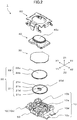
- FIG. 2 is an exploded perspective view of the push switch 1.
- FIG. 3 is a plan view of the push switch 1.
- FIG. 4 is a cross-sectional view taken along line IV-IV of FIG. 3 .
- FIG. 5 is a drawing illustrating a state where inversion of a dome part 21a in the cross section of FIG. 4 is completed.
- FIG. 6 is a drawing illustrating a state where the dome part 21a is further pressed from the state in FIG. 5 .
- the push switch 1 of the present embodiment includes a housing 50, a fixed contact 10, a movable contact 20, a sheet 30, an operation part 40, and a cover 60.
- the housing 50 is formed by injection-molding an insulating synthetic resin. As illustrated in FIGs. 2 and 4 , the fixed contact 10 is embedded in the housing 50, and a housing space for housing the movable contact 20 is formed in the housing 50.
- the fixed contact 10 is formed by machining a conductive metal plate.
- the fixed contact 10 includes a first fixed contact 10a that is disposed in the middle of the housing 50 such that the Z1 side of the first fixed contact 10a is exposed, and second fixed contacts 10b that are disposed apart from and around the fixed contact 10a.
- the first fixed contact 10a is connected to terminals 10c that protrude from the X1 and X2 ends of the housing 50.
- the second fixed contacts 10b are connected to terminals 10d that protrude from the X1 and X2 ends of the housing 50. In the initial state of the push switch 1, the terminals 10c and the terminals 10d are electrically insulated from each other.
- the movable contact 20 is formed by machining a conductive metal plate.
- the movable contact 20 includes a first movable contact 21 and a second movable contact 22 that are stacked on each other.
- the movable contact 20 may include only the first movable contact 21.
- the first movable contact 21 includes a dome part 21a that is shaped like a dome and can be inverted in shape when pressed, a skirt 21b that continuously surrounds and extends outward from the circumference of the dome part 21a, and a tongue part 21d that is shaped like a plate spring and formed near a top part 21c of the dome part 21a.
- the tongue part 21d functions as a contact part 20d that can elastically contact the first fixed contact 10a.
- the second movable contact 22 includes a dome part 22a that is shaped like a dome and can be inverted in shape when pressed, and a skirt 22b that continuously surrounds and extends outward from the circumference of the dome part 22a. As illustrated in FIG. 4 , the second movable contact 22 is shaped to fit over the first movable contact 21, and functions together with the first movable contact 21.
- the sheet 30 is shaped like a sheet and formed of an insulating synthetic resin.
- the sheet 30 is disposed over the Z1 side of the movable contact 20 to cover the housing space of the housing 50 for housing the movable contact 20.
- the operation part 40 is formed by injection-molding a synthetic resin, and is disposed to press the movable contact 20 via the sheet 30.
- the operation part 40 includes an operating part 40a that protrudes in the Z1 direction and is to be pressed by an operator.
- the cover 60 is formed by machining a metal plate, and is disposed over the housing 50.
- the cover 60 covers the movable contact 20 and the sheet 30, and also covers the operation part 40 such that the operating part 40a is exposed through an opening of the cover 60.
- the cover 60 is attached to the side walls of the housing 50.
- the first fixed contact 10a is not in contact with the dome part 21a of the movable contact 20 (the first movable contact 21).
- the second fixed contacts 10b are in contact with the skirt 21b of the movable contact 20 (the first movable contact 21).
- the terminals 10c and the terminals 10d are not electrically connected with each other.
- the operation part 40 causes the sheet 30 to sag and presses the dome part 22a in the Z2 direction.
- the sheet 30 and the dome parts 21a and 22a of the movable contact 20 are elastically deformed.
- the pressing stroke amount reaches a predetermined amount (a maximum load position P1 in FIG. 7 )
- the dome parts 21a and 22a start to be inverted and are elastically deformed until the inversion is completed.
- the push switch 1 of the present embodiment is configured such that only the contact part 20d (the tongue part 21d) contacts the first fixed contact 10a.
- the dome part 21a contacts the first fixed contact 10a as illustrated in FIG. 6 .
- the dome part 21a does not tend to be elastically deformed further and the operating load felt by the operator sharply increases.
- the above configuration of the push switch 1 of the present embodiment is a difference from the related-art configuration. To more clearly explain the difference, the push switch 1 of the present embodiment is compared with a related-art push switch of a comparative example by referring to FIGs. 4 through 8 .
- FIGs. 7 (a) through 7 (d) are drawings illustrating operations of the push switch 1 of the present embodiment
- FIG. 7 (a) is a drawing illustrating a relationship between a pressing stroke and an operating load felt by an operator
- FIG. 7 (b) is a cross-sectional view corresponding to a maximum load position P1
- FIG. 7 (c) is a cross-sectional view corresponding to an inversion completion position P2 at which inversion of the dome part 21a is completed
- FIG. 7 (d) is a cross-sectional view corresponding to a predetermined position P3 to which the dome part 21a is further pressed.
- FIGs. 8 (a) through 8 (d) are drawings illustrating operations of a related-art push switch of a comparative example
- FIG. 8 (a) through 8 (d) are drawings illustrating operations of a related-art push switch of a comparative example
- FIG. 8 (a) is a drawing illustrating a relationship between a pressing stroke and an operating load felt by an operator
- FIG. 8 (b) is a cross-sectional view corresponding to a pressing stroke position PA0 in the initial state
- FIG. 8 (c) is a cross-sectional view corresponding to a maximum load position PA1
- FIG. 8 (d) is a cross-sectional view corresponding to a contact position PA3 of an inverted dome part A21a.
- the operating load felt by the operator nonlinearly changes as the position of the pressing stroke changes.
- the operating load at the pressing stroke position P0 in the initial state is 0.
- the operating load necessary to press the movable contact 20 gradually increases.
- the operating load decreases when the dome parts 21a and 22a are inverted and increases again when the movable contact 20 is pressed further.
- the movable contact 20 is not in contact with the first fixed contact 10a as illustrated in FIG. 4 and the push switch 1 is OFF.
- the operating load increases along with the elastic deformation of the dome parts 21a and 22a until the pressing stroke reaches the maximum load position P1.
- the dome shapes of the dome parts 21a and 22a sag as illustrated in FIG. 7 (b) .
- the dome parts 21a and 22a start to be inverted.
- the operating load becomes maximum at the maximum load position P1, and decreases when the operating part 40a is further pressed and the dome parts 21a and 22a start to be inverted.
- the operator pressing the operating part 40a gets a feel that the switch is pushed in.
- the pressing stroke reaches the inversion completion positon P2.
- the inversion completion position P2 the inversion of the dome parts 21a and 22a is completed and as illustrated in FIG. 7 (c) , only the tongue part 21d, which protrudes toward the inside of the dome part 21a from a position near the top part 21c of the dome part 21a and is shaped like a plate spring, elastically contacts the first fixed contact 10a.
- the tongue part 21d functions as the contact part 20d that can elastically contact the first fixed contact 10a, and the first fixed contact 10a is electrically connected via the movable contact 20 to the second fixed contacts 10b. That is, the switch is turned on.
- the first fixed contact 10a is disposed such that the dome parts 21a and 22a (dome-shaped parts other than the tongue part 21d) do not contact the first fixed contact 10a when the inversion of the dome parts 21a and 22a is completed. Therefore, the dome parts 21a and 22a contact the first fixed contact 10a after an inflection point at which the decreased operating load starts to increase again. More specifically, the fixed contact 10 is arranged in the housing 50 such that the first fixed contact 10a is shifted in the Z2 direction relative to the second fixed contacts 10b. With this configuration, at the timing when the inversion of the dome parts 21a and 22a is completed, as illustrated in FIG.
- the top part 21c of the dome part 21a is not in contact with the first fixed contact 10a, and only the tongue part 21d, which is shaped like a plate spring and elastically deformable, is in contact with the first fixed contact 10a.
- the protruding length of the tongue part 21d is preferably set such that the tongue part 21d contacts the first fixed contact 10a slightly before the pressing stroke reaches the inversion completion position P2. This enables the tongue part 21d to reliably contact the first fixed contact 10a due to elasticity when the inversion of the dome parts 21a and 22a is completed, and enables stable electric connection.
- the tongue part 21d is caused to firmly contact the first fixed contact 10a and the top part 21c of the dome part 21a contacts the first fixed contact 10a at the predetermined pressing stroke position P3 of the pressing stroke. After this state, the operating load sharply increases.
- the push switch of the comparative example includes a movable contact A20 that includes dome parts A21a and A22a that are shaped like a dome and can be inverted in shape when pressed.
- the dome parts A21a and A22a are apart from a first fixed contact A10a.
- Skirts A21b and A22b are in contact with second fixed contacts A10b.
- the first fixed contact A10a is disposed at the same height as the second fixed contacts A10b such that a top part A21c contacts the first fixed contact A10a in the middle of inversion of the dome parts A21a and A22a.
- the dome parts A21a and A22a sag at a maximum load position PA1 as illustrated in FIG. 8 (c) .
- the dome parts A21a and A22a contact the first fixed contact A10a at a contact position PA3 in the middle of the inversion of the dome parts A21a and A22a.
- the push switch is configured such that the pressing stroke amount at the contact position PA3 is smaller than the pressing stroke amount at a virtual inversion completion position PA2 at which the inversion of the dome parts A21a and A22a is supposed to be completed.
- the dome parts A21a and A22a reliably contact the first fixed contact A10a in the middle of inversion, and the push switch is turned on. In this state, the dome parts A21a and A22a firmly contact the first fixed contact A10a, and the operating load sharply increases.
- the related-art push switch of the comparative example has a problem where a sound is generated when the push switch is turned on. This problem is assumed to be cause by the reasons described below.
- the dome parts A21a and A22a start to be inverted while storing kinetic energy that is generated by elastic deformation (see FIG. 8 (b) ) immediately before the inversion. For this reason, when the dome parts A21a and A22a collide with the first fixed contact A10a before the inversion is completed, the stored kinetic energy is converted into collision energy. This increases the collision sound generated when metal parts collide with each other. When the thickness of the dome parts A21a and A22a is reduced so that the dome parts A21a and A22a can be elastically deformed more easily and the collision sound can be reduced, the amount of change in the operating load also becomes small and the click feel is reduced.
- the operating load necessary to invert the dome parts A21a and A22a is increased to achieve a clearer click feel by, for example, increasing the thickness of the dome parts A21a and A22a, the kinetic energy generated by elastic deformation increases, and the collision sound generated when the dome parts A21a and A22a collide with the first fixed contact A10a increases.
- the operating load necessary to invert the dome parts 21a and 22a is increased to achieve a clearer click feel by, for example, increasing the thickness of the dome parts 21a and 22a; and the first fixed contact 10a is placed in such a position that the top part 21c of the dome part 21a does not contact the first fixed contact 10a at the timing when the inversion of the dome parts 21a and 22a is completed.
- the kinetic energy generated by elastic deformation immediately before the inversion and stored in the dome parts 21a and 22a is used for thermal energy (e.g., vibration) after the inversion is completed.
- the tongue part 21d shaped like a plate spring is provided as the contact part 20d that contacts the first fixed contact 10a.
- the spring constant of the contact part 20d (the tongue part 21d) is less than the spring constant of the dome parts 21a and 22a.
- the tongue part 21d contacts the first fixed contact 10a before the inversion of the dome parts 21a and 22a is completed, the collision sound is small because the tongue part 21d has a small spring constant and is elastically deformed easily.
- the elasticity of the tongue part 21d functions as a cushion and reduces the impact generated when the dome part 21a is pressed to a position at which the dome part 21a contacts the first fixed contact 10a.
- the configuration of the push switch 1 of the present embodiment makes it possible to prevent the kinetic energy, which is generated while the dome parts 21a and 22a are inverted, from being added to collision energy with which the dome part 21a contacts the first fixed contact 10a.
- the present embodiment provides a push switch with a good operation feel as well as a small operation sound.
- the first fixed contact 10a is placed in such a position that the amount of pressing stroke up to the predetermined position P3 is 1.1 to 1.2 times greater than the amount of pressing stroke up to the inversion completion position P2 at which the inversion of the dome parts 21a and 22a is completed. It is possible to reduce the collision sound by setting the predetermined position P3 at which the dome part 21a contacts the first fixed contact 10a such that the amount of pressing stroke up to the predetermined position P3 becomes steadily greater than the amount of pressing stroke up to the inversion completion position P2 at which the inversion of the dome part 21a is completed. Further, the present embodiment makes it possible to reduce the odd feeling that is felt when the amount of pressing stroke necessary after the inversion is too large.
- the push switch 1 of the present embodiment can be designed and manufactured by adjusting the sizes of the skirt 21b and the tongue part 21d as necessary.
- the push switch 1 can be easily optimized to achieve a desired operation feel and a desired operation sound.
- the ON timing at which the switch is electrically turned on can be adjusted to match a pressing stroke position at which a click feel is obtained.
- the push switch 1 of the present embodiment includes the movable contact 20 including the dome part 21a that is shaped like a dome and can be inverted in shape when pressed, and the fixed contact 10 including the first fixed contact 10a.
- the movable contact 20 is configured to be brought into contact with and away from the first fixed contact 10a. After the movable contact 20 starts to be pressed, the operating load necessary to press the movable contact 20 gradually increases. Then, the operating load decreases when the dome part 21a is inverted, and increases again when the movable contact 20 is pressed further.
- the dome part 21a contacts the first fixed contact 10a after an inflection point at which the decreased operating load starts to increase again.
- the dome part 21a contacts the first fixed contact 10a after an inflection point at which the decreased operating load starts to increase again, i.e., after the inversion is completed and the kinetic energy is reduced. This in turn makes it possible to reduce the collision energy with which the movable contact 20 collides with the first fixed contact 10a and thereby reduce the collision sound (operation sound).
- the movable contact 20 is disposed such that the dome part 21a contacts the first fixed contact 10a when the movable contact 20 is pressed further to the predetermined pressing stroke position P3 from the inversion completion position P2 at which the inversion of the dome part 21a is completed.
- This configuration makes it possible to prevent the kinetic energy, which is generated while the dome part 21a is inverted, from being added to the collision energy and thereby makes it possible to reduce the collision sound.
- the first fixed contact 10a is preferably placed in such a position that the amount of pressing stroke up to the predetermined position P3 is 1.1 to 1.2 times greater than the amount of pressing stroke up to the inversion completion position P2 at which the inversion of the dome part 21a is completed.
- This configuration makes it possible to set the predetermined position P3 at which the dome part 21a contacts the first fixed contact 10a such that the amount of pressing stroke up to the predetermined position P3 becomes steadily greater than the amount of pressing stroke up to the inversion completion position P2 at which the inversion of the dome part 21a is completed, and thereby makes it possible to reduce the collision sound. Further, this configuration makes it possible to reduce the odd feeling that is felt when the amount of pressing stroke necessary after the inversion is too large.
- the movable contact 20 of the push switch 1 of the present embodiment includes the contact part 20d configured to elastically contact the first fixed contact 10a of the fixed contact 10 at a pressing stroke position up to the inversion completion position P2 at which the inversion of the dome part 21a is completed.
- This configuration makes it possible to adjust the ON timing such that the switch is electrically turned on at a pressing stroke position that is before the pressing stroke position at which the dome part 21a contacts the first fixed contact 10a.
- the movable contact 20 of the push switch 1 of the present embodiment preferably includes the skirt 21b that continuously surrounds and extends outward from the circumference of the dome part 21a and the tongue part 21d that is shaped like a plate spring and protrudes toward the inside of the dome part 21a.
- This configuration makes it possible to adjust the ON timing such that only the tongue part 21d contacts the first fixed contact 10a when the inversion of the dome part 21a is completed.
- the push switch 1 of the present embodiment is configured such that the spring constant of the contact part 20d is less than the spring constant of the dome part 21a.
- This configuration makes it possible to make the collision energy less than the collision energy of the dome part 21a being inverted, and thereby makes it possible to reduce the collision sound of the contact part 20d.
- the push switch 1 according to an embodiment of the present invention is described above.
- the present invention is not limited to the specifically disclosed embodiment, and variations and modifications may be made without departing from the scope of the present invention.
- variations of the push switch 1 described below are also within the scope of the present invention.
Landscapes
- Push-Button Switches (AREA)
Abstract
Description
- The present invention relates to a push switch having a click feel.
-
Patent Document 1, for example, discloses a push switch having a click feel. -
FIG. 10 is an exploded perspective view of apush switch 100 disclosed inPatent Document 1.FIGs. 11 (a) and 11(b) are cross-sectional views of the related-art push switch 100.FIG. 11 (a) is a cross-sectional view illustrating an initial state where thepush switch 100 is not being pressed.FIG. 11 (b) is a cross-sectional view illustrating a state where thepush switch 100 is being pressed. - As illustrated in
FIG. 10 , thepush switch 100 includes amovable contact 101 including around part 101a having a dome shape, ahousing 102 including arecess 102a for housing themovable contact 101 and a fixedcontact 103 to be brought into contact with themovable contact 101, and asheet 104 including a pressedpart 104a that covers therecess 102a of thehousing 102 and is pressed from the outside. - As illustrated in
FIG. 11 (a) , before thepush switch 100 is pressed, theround part 101a of themovable contact 101 is not inverted in shape, and a first fixedcontact 103a and secondfixed contacts 103b are not electrically connected to each other. In the state ofFIG. 11 (a) , when the pressedpart 104a of thesheet 104 is pressed in the Z2 direction by a pressing part OP of an electronic apparatus where thepush switch 100 is installed, theround part 101a of themovable contact 101 is pressed via thesheet 104 as illustrated inFIG. 11 (b) . The pressedround part 101a sags in the Z2 direction and is inverted in shape, and contacts the first fixedcontact 103a. When theround part 101a contacts the firstfixed contact 103a, the firstfixed contact 103a and the secondfixed contacts 103b are electrically connected to each other via themovable contact 101. - The
push switch 100 is configured such that theround part 101a collides with thefixed contact 103 before theround part 101a is completely inverted. - [Patent Document 1] Japanese Laid-Open Patent Publication No.
2014-13672 - However, a push switch such as the
push switch 100 having a click feel has a problem where a sound is generated when the push switch is turned on. The main causes of the operation sound generated when the push switch is turned on are supposed to be a collision sound that is generated when theround part 101a of themovable contact 101 collides with the first fixedcontact 103a and the vibration of theround part 101a. Accordingly, the operation sound increases as the force of inversion of theround part 101a increases. Thus, there is a problem that the operation sound increases as the click feel is made clearer, and it is difficult to provide a switch with a small operation sound. - One object of the present invention is to solve the above problem and to provide a push switch with a good click feel as well as a small operation sound.
- A push switch of the present invention includes a movable contact including a dome part that is shaped like a dome and configured to be inverted in shape when pressed, and a fixed contact including a first fixed contact, the movable contact being configured to be brought into contact with and away from the first fixed contact. The push switch is configured such that an operating load necessary to press the movable contact gradually increases after the movable contact starts to be pressed, decreases thereafter when the dome part is inverted, and increases again when the movable contact is further pressed, and the dome part contacts the first fixed contact after an inflection point at which the decreased operating load starts to increase again.
- With this configuration, the dome part contacts the first fixed contact after an inflection point at which the decreased operating load starts to increase, i.e., after the inversion is completed and the kinetic energy is reduced. This in turn makes it possible to reduce collision energy with which the movable contact collides with the first fixed contact and thereby reduce a collision sound (operation sound).
- In the push switch of the present invention, the movable contact is disposed such that the dome part contacts the first fixed contact when the movable contact is pressed further to a predetermined pressing stroke position from an inversion completion position at which the inversion of the dome part is completed.
- This configuration makes it possible to prevent kinetic energy, which is generated while the dome part is inverted, from being added to the collision energy and thereby makes it possible to reduce the collision sound.
- In the push switch of the present invention, the first fixed contact is preferably placed in such a position that the amount of pressing stroke up to the predetermined pressing stroke position is 1.1 to 1.2 times greater than the amount of pressing stroke up to the inversion completion position at which the inversion of the dome part is completed.
- This configuration makes it possible to set the predetermined position at which the dome part contacts the first fixed contact such that the amount of pressing stroke up to the predetermined position becomes steadily greater than the amount of pressing stroke up to the inversion completion position at which the inversion of the dome part is completed, and thereby makes it possible to reduce the collision sound. This configuration also makes it possible to reduce the odd feeling that is felt when the amount of pressing stroke necessary after the inversion is too large.
- In the push switch of the present invention, one of the movable contact and the fixed contact includes a contact part that is configured to elastically contact another one of the movable contact and the fixed contact at a pressing stroke position up to an inversion completion position at which the inversion of the dome part is completed.
- This configuration makes it possible to adjust the ON timing such that the switch is electrically turned on at a pressing stroke position that is before the pressing stroke position at which the dome part contacts the first fixed contact.
- In the push switch of the present invention, the movable contact includes the dome part, a skirt that continuously surrounds and extends outward from a circumference of the dome part, and a tongue part that is shaped like an elastically-deformable plate spring and protrudes toward the inside of the dome part from a position near a top part of the dome part; and the contact part is the tongue part.
- This configuration makes it possible to adjust the ON timing such that only the tongue part contacts the first fixed contact when the inversion of the dome part is completed.
- In the push switch of the present invention, the spring constant of the contact part is less than the spring constant of the dome part.
- This configuration makes it possible to make the collision energy less than the collision energy of the dome part being inverted, and thereby makes it possible to reduce the collision sound of the contact part.
- According to the present invention, the dome part contacts the first fixed contact after an inflection point at which the decreased operating load starts to increase again. This configuration makes it possible to reduce the collision energy and thereby reduce the collision sound. Thus, the present invention makes it possible to provide a push switch with a good click feel as well as a small operation sound.
-
-
FIG. 1 is a perspective view of a push switch according to an embodiment of the present invention; -
FIG. 2 is an exploded perspective view of a push switch according to an embodiment of the present invention; -
FIG. 3 is a plan view of a push switch according to an embodiment of the present invention; -
FIG. 4 is a cross-sectional view taken along line IV-IV ofFIG. 3 ; -
FIG. 5 is a drawing illustrating a state where inversion of a dome part in the cross section ofFIG. 4 is completed; -
FIG. 6 is a drawing illustrating a state where the dome part is further pressed from the state inFIG. 5 ; -
FIGs. 7 (a) through 7 (d) are drawings illustrating operations of a push switch of an embodiment,FIG. 7 (a) is a drawing illustrating a relationship between a pressing stroke and an operating load felt by an operator,FIG. 7 (b) is a cross-sectional view corresponding to a maximum load position,FIG. 7 (c) is a cross-sectional view corresponding to a position where inversion of a dome part is completed, andFIG. 7 (d) is a cross-sectional view corresponding to a predetermined position to which the dome part is further pressed; -
FIGs. 8 (a) through 8 (d) are drawings illustrating operations of a related-art push switch of a comparative example,FIG. 8 (a) is a drawing illustrating a relationship between a pressing stroke and an operating load felt by an operator,FIG. 8 (b) is a cross-sectional view corresponding to a pressing stroke position in an initial state,FIG. 8 (c) is a cross-sectional view corresponding to a maximum load position, andFIG. 8 (d) is a cross-sectional view corresponding to a contact position of an inverted dome part; -
FIG. 9 is a cross-sectional view of a variation of a push switch; -
FIG. 10 is an exploded perspective view of a related-art push switch; and -
FIGs. 11 (a) and 11 (b) are cross-sectional views of a related-art push switch 100,FIG. 11 (a) is a cross-sectional view illustrating an initial state where the push switch is not being pressed, andFIG. 11 (b) is a cross-sectional view illustrating a state where the push switch is being pressed. - An embodiment of the present invention is described below with reference to the accompanying drawings. For clarity, dimensions of components in the drawings are changed as necessary.
-
FIG. 1 is a perspective view of apush switch 1 according to an embodiment of the present invention.FIG. 2 is an exploded perspective view of thepush switch 1.FIG. 3 is a plan view of thepush switch 1.FIG. 4 is a cross-sectional view taken along line IV-IV ofFIG. 3 .FIG. 5 is a drawing illustrating a state where inversion of adome part 21a in the cross section ofFIG. 4 is completed.FIG. 6 is a drawing illustrating a state where thedome part 21a is further pressed from the state inFIG. 5 . - As illustrated by
FIGs. 1 through 4 , thepush switch 1 of the present embodiment includes ahousing 50, a fixedcontact 10, amovable contact 20, asheet 30, anoperation part 40, and acover 60. - The
housing 50 is formed by injection-molding an insulating synthetic resin. As illustrated inFIGs. 2 and4 , the fixedcontact 10 is embedded in thehousing 50, and a housing space for housing themovable contact 20 is formed in thehousing 50. - The fixed
contact 10 is formed by machining a conductive metal plate. The fixedcontact 10 includes a firstfixed contact 10a that is disposed in the middle of thehousing 50 such that the Z1 side of the firstfixed contact 10a is exposed, and secondfixed contacts 10b that are disposed apart from and around the fixedcontact 10a. The firstfixed contact 10a is connected toterminals 10c that protrude from the X1 and X2 ends of thehousing 50. The secondfixed contacts 10b are connected toterminals 10d that protrude from the X1 and X2 ends of thehousing 50. In the initial state of thepush switch 1, theterminals 10c and theterminals 10d are electrically insulated from each other. - The
movable contact 20 is formed by machining a conductive metal plate. In thepush switch 1 of the present embodiment, themovable contact 20 includes a firstmovable contact 21 and a secondmovable contact 22 that are stacked on each other. Alternatively, themovable contact 20 may include only the firstmovable contact 21. - The first
movable contact 21 includes adome part 21a that is shaped like a dome and can be inverted in shape when pressed, askirt 21b that continuously surrounds and extends outward from the circumference of thedome part 21a, and atongue part 21d that is shaped like a plate spring and formed near atop part 21c of thedome part 21a. As described below, thetongue part 21d functions as acontact part 20d that can elastically contact the firstfixed contact 10a. - The second
movable contact 22 includes adome part 22a that is shaped like a dome and can be inverted in shape when pressed, and askirt 22b that continuously surrounds and extends outward from the circumference of thedome part 22a. As illustrated inFIG. 4 , the secondmovable contact 22 is shaped to fit over the firstmovable contact 21, and functions together with the firstmovable contact 21. - The
sheet 30 is shaped like a sheet and formed of an insulating synthetic resin. Thesheet 30 is disposed over the Z1 side of themovable contact 20 to cover the housing space of thehousing 50 for housing themovable contact 20. - The
operation part 40 is formed by injection-molding a synthetic resin, and is disposed to press themovable contact 20 via thesheet 30. Theoperation part 40 includes anoperating part 40a that protrudes in the Z1 direction and is to be pressed by an operator. - The
cover 60 is formed by machining a metal plate, and is disposed over thehousing 50. Thecover 60 covers themovable contact 20 and thesheet 30, and also covers theoperation part 40 such that the operatingpart 40a is exposed through an opening of thecover 60. Thecover 60 is attached to the side walls of thehousing 50. - In the initial state, as illustrated in
FIG. 4 , the firstfixed contact 10a is not in contact with thedome part 21a of the movable contact 20 (the first movable contact 21). The secondfixed contacts 10b are in contact with theskirt 21b of the movable contact 20 (the first movable contact 21). In this initial state, theterminals 10c and theterminals 10d are not electrically connected with each other. - When an operator presses the operating
part 40a in the Z2 direction, theoperation part 40 causes thesheet 30 to sag and presses thedome part 22a in the Z2 direction. As a result, thesheet 30 and thedome parts movable contact 20 are elastically deformed. When the pressing stroke amount reaches a predetermined amount (a maximum load position P1 inFIG. 7 ), thedome parts FIG. 5 , thepush switch 1 of the present embodiment is configured such that only thecontact part 20d (thetongue part 21d) contacts the firstfixed contact 10a. When theoperation part 40 is further pressed from this state, thedome part 21a contacts the firstfixed contact 10a as illustrated inFIG. 6 . In the state where thedome part 21a is in contact with the firstfixed contact 10a, even when theoperation part 40 is pressed further, thedome part 21a does not tend to be elastically deformed further and the operating load felt by the operator sharply increases. - The above configuration of the
push switch 1 of the present embodiment is a difference from the related-art configuration. To more clearly explain the difference, thepush switch 1 of the present embodiment is compared with a related-art push switch of a comparative example by referring toFIGs. 4 through 8 . -
FIGs. 7 (a) through 7 (d) are drawings illustrating operations of thepush switch 1 of the present embodiment,FIG. 7 (a) is a drawing illustrating a relationship between a pressing stroke and an operating load felt by an operator,FIG. 7 (b) is a cross-sectional view corresponding to a maximum load position P1,FIG. 7 (c) is a cross-sectional view corresponding to an inversion completion position P2 at which inversion of thedome part 21a is completed, andFIG. 7 (d) is a cross-sectional view corresponding to a predetermined position P3 to which thedome part 21a is further pressed.FIGs. 8 (a) through 8 (d) are drawings illustrating operations of a related-art push switch of a comparative example,FIG. 8 (a) is a drawing illustrating a relationship between a pressing stroke and an operating load felt by an operator,FIG. 8 (b) is a cross-sectional view corresponding to a pressing stroke position PA0 in the initial state,FIG. 8 (c) is a cross-sectional view corresponding to a maximum load position PA1, andFIG. 8 (d) is a cross-sectional view corresponding to a contact position PA3 of an inverted dome part A21a. - As illustrated by
FIG. 7 (a) , with thepush switch 1 of the present embodiment, the operating load felt by the operator nonlinearly changes as the position of the pressing stroke changes. The operating load at the pressing stroke position P0 in the initial state is 0. After themovable contact 20 starts to be pressed, the operating load necessary to press themovable contact 20 gradually increases. Then, the operating load decreases when thedome parts movable contact 20 is pressed further. A relationship between pressing stroke positions and the states of elastic deformation of themovable contact 20, which causes changes in the operating load, is described in more detail below. - At the pressing stroke position P0 in the initial state, the
movable contact 20 is not in contact with the firstfixed contact 10a as illustrated inFIG. 4 and thepush switch 1 is OFF. - When the operating
part 40a (seeFIG. 4 ) is pressed, the operating load increases along with the elastic deformation of thedome parts dome parts FIG. 7 (b) . When the operatingpart 40a is further pressed, thedome parts FIG. 7 (a) , the operating load becomes maximum at the maximum load position P1, and decreases when the operatingpart 40a is further pressed and thedome parts operating part 40a gets a feel that the switch is pushed in. When the operator continues to press the operatingpart 40a, the pressing stroke reaches the inversion completion positon P2. At the inversion completion position P2, the inversion of thedome parts FIG. 7 (c) , only thetongue part 21d, which protrudes toward the inside of thedome part 21a from a position near thetop part 21c of thedome part 21a and is shaped like a plate spring, elastically contacts the firstfixed contact 10a. As a result, thetongue part 21d functions as thecontact part 20d that can elastically contact the firstfixed contact 10a, and the firstfixed contact 10a is electrically connected via themovable contact 20 to the secondfixed contacts 10b. That is, the switch is turned on. - In the
push switch 1 of the present embodiment, the firstfixed contact 10a is disposed such that thedome parts tongue part 21d) do not contact the firstfixed contact 10a when the inversion of thedome parts dome parts fixed contact 10a after an inflection point at which the decreased operating load starts to increase again. More specifically, the fixedcontact 10 is arranged in thehousing 50 such that the firstfixed contact 10a is shifted in the Z2 direction relative to the secondfixed contacts 10b. With this configuration, at the timing when the inversion of thedome parts FIG. 7 (c) , thetop part 21c of thedome part 21a is not in contact with the firstfixed contact 10a, and only thetongue part 21d, which is shaped like a plate spring and elastically deformable, is in contact with the firstfixed contact 10a. The protruding length of thetongue part 21d is preferably set such that thetongue part 21d contacts the firstfixed contact 10a slightly before the pressing stroke reaches the inversion completion position P2. This enables thetongue part 21d to reliably contact the firstfixed contact 10a due to elasticity when the inversion of thedome parts - When the operating
part 40a is further pressed, as illustrated inFIG. 7 (d) , thetongue part 21d is caused to firmly contact the firstfixed contact 10a and thetop part 21c of thedome part 21a contacts the firstfixed contact 10a at the predetermined pressing stroke position P3 of the pressing stroke. After this state, the operating load sharply increases. - To further clarify the above features of the
push switch 1, operations of a related-art push switch of a comparative example are described below. - As illustrated by
FIG. 8 (a) , with the related-art push switch of the comparative example, the operating load felt by the operator increases, decreases, and then sharply increases as the position of the pressing stroke changes. - As illustrated in
FIG. 8 (b) , the push switch of the comparative example includes a movable contact A20 that includes dome parts A21a and A22a that are shaped like a dome and can be inverted in shape when pressed. In the initial state, the dome parts A21a and A22a are apart from a first fixed contact A10a. Skirts A21b and A22b are in contact with second fixed contacts A10b. The first fixed contact A10a is disposed at the same height as the second fixed contacts A10b such that a top part A21c contacts the first fixed contact A10a in the middle of inversion of the dome parts A21a and A22a. With this configuration, the dome parts A21a and A22a sag at a maximum load position PA1 as illustrated inFIG. 8 (c) . When further pressed, as illustrated inFIG. 8 (d) , the dome parts A21a and A22a contact the first fixed contact A10a at a contact position PA3 in the middle of the inversion of the dome parts A21a and A22a. As illustrated inFIG. 8 (a) , the push switch is configured such that the pressing stroke amount at the contact position PA3 is smaller than the pressing stroke amount at a virtual inversion completion position PA2 at which the inversion of the dome parts A21a and A22a is supposed to be completed. With this configuration, the dome parts A21a and A22a reliably contact the first fixed contact A10a in the middle of inversion, and the push switch is turned on. In this state, the dome parts A21a and A22a firmly contact the first fixed contact A10a, and the operating load sharply increases. - The related-art push switch of the comparative example has a problem where a sound is generated when the push switch is turned on. This problem is assumed to be cause by the reasons described below.
- The dome parts A21a and A22a start to be inverted while storing kinetic energy that is generated by elastic deformation (see
FIG. 8 (b) ) immediately before the inversion. For this reason, when the dome parts A21a and A22a collide with the first fixed contact A10a before the inversion is completed, the stored kinetic energy is converted into collision energy. This increases the collision sound generated when metal parts collide with each other. When the thickness of the dome parts A21a and A22a is reduced so that the dome parts A21a and A22a can be elastically deformed more easily and the collision sound can be reduced, the amount of change in the operating load also becomes small and the click feel is reduced. Also, when the operating load necessary to invert the dome parts A21a and A22a is increased to achieve a clearer click feel by, for example, increasing the thickness of the dome parts A21a and A22a, the kinetic energy generated by elastic deformation increases, and the collision sound generated when the dome parts A21a and A22a collide with the first fixed contact A10a increases. - The above problems of the related-art configuration are solved by the
push switch 1 of the present embodiment. In the present embodiment, the operating load necessary to invert thedome parts dome parts fixed contact 10a is placed in such a position that thetop part 21c of thedome part 21a does not contact the firstfixed contact 10a at the timing when the inversion of thedome parts dome parts push switch 1 of the present embodiment, thetongue part 21d shaped like a plate spring is provided as thecontact part 20d that contacts the firstfixed contact 10a. In thepush switch 1, the spring constant of thecontact part 20d (thetongue part 21d) is less than the spring constant of thedome parts tongue part 21d contacts the firstfixed contact 10a before the inversion of thedome parts tongue part 21d has a small spring constant and is elastically deformed easily. After thetongue part 21d contacts the firstfixed contact 10a, the elasticity of thetongue part 21d functions as a cushion and reduces the impact generated when thedome part 21a is pressed to a position at which thedome part 21a contacts the firstfixed contact 10a. As described above, the configuration of thepush switch 1 of the present embodiment makes it possible to prevent the kinetic energy, which is generated while thedome parts dome part 21a contacts the firstfixed contact 10a. Thus, the present embodiment provides a push switch with a good operation feel as well as a small operation sound. - In the
push switch 1 of the present embodiment, the firstfixed contact 10a is placed in such a position that the amount of pressing stroke up to the predetermined position P3 is 1.1 to 1.2 times greater than the amount of pressing stroke up to the inversion completion position P2 at which the inversion of thedome parts dome part 21a contacts the firstfixed contact 10a such that the amount of pressing stroke up to the predetermined position P3 becomes steadily greater than the amount of pressing stroke up to the inversion completion position P2 at which the inversion of thedome part 21a is completed. Further, the present embodiment makes it possible to reduce the odd feeling that is felt when the amount of pressing stroke necessary after the inversion is too large. - Because the related-art push switch of the comparative example needs to be configured such that the dome parts A21a and A22a collide with the first fixed contact A10a while being inverted, it is difficult to design and manufacture the
movable contact 20. Thepush switch 1 of the present embodiment can be designed and manufactured by adjusting the sizes of theskirt 21b and thetongue part 21d as necessary. Thus, thepush switch 1 can be easily optimized to achieve a desired operation feel and a desired operation sound. Also, the ON timing at which the switch is electrically turned on can be adjusted to match a pressing stroke position at which a click feel is obtained. - Next, effects of the present embodiment are described.
- The
push switch 1 of the present embodiment includes themovable contact 20 including thedome part 21a that is shaped like a dome and can be inverted in shape when pressed, and the fixedcontact 10 including the firstfixed contact 10a. Themovable contact 20 is configured to be brought into contact with and away from the firstfixed contact 10a. After themovable contact 20 starts to be pressed, the operating load necessary to press themovable contact 20 gradually increases. Then, the operating load decreases when thedome part 21a is inverted, and increases again when themovable contact 20 is pressed further. Thedome part 21a contacts the firstfixed contact 10a after an inflection point at which the decreased operating load starts to increase again. - With this configuration, the
dome part 21a contacts the firstfixed contact 10a after an inflection point at which the decreased operating load starts to increase again, i.e., after the inversion is completed and the kinetic energy is reduced. This in turn makes it possible to reduce the collision energy with which themovable contact 20 collides with the firstfixed contact 10a and thereby reduce the collision sound (operation sound). - The
movable contact 20 is disposed such that thedome part 21a contacts the firstfixed contact 10a when themovable contact 20 is pressed further to the predetermined pressing stroke position P3 from the inversion completion position P2 at which the inversion of thedome part 21a is completed. - This configuration makes it possible to prevent the kinetic energy, which is generated while the
dome part 21a is inverted, from being added to the collision energy and thereby makes it possible to reduce the collision sound. - The first
fixed contact 10a is preferably placed in such a position that the amount of pressing stroke up to the predetermined position P3 is 1.1 to 1.2 times greater than the amount of pressing stroke up to the inversion completion position P2 at which the inversion of thedome part 21a is completed. - This configuration makes it possible to set the predetermined position P3 at which the
dome part 21a contacts the firstfixed contact 10a such that the amount of pressing stroke up to the predetermined position P3 becomes steadily greater than the amount of pressing stroke up to the inversion completion position P2 at which the inversion of thedome part 21a is completed, and thereby makes it possible to reduce the collision sound. Further, this configuration makes it possible to reduce the odd feeling that is felt when the amount of pressing stroke necessary after the inversion is too large. - Also, the
movable contact 20 of thepush switch 1 of the present embodiment includes thecontact part 20d configured to elastically contact the firstfixed contact 10a of the fixedcontact 10 at a pressing stroke position up to the inversion completion position P2 at which the inversion of thedome part 21a is completed. - This configuration makes it possible to adjust the ON timing such that the switch is electrically turned on at a pressing stroke position that is before the pressing stroke position at which the
dome part 21a contacts the firstfixed contact 10a. - The
movable contact 20 of thepush switch 1 of the present embodiment preferably includes theskirt 21b that continuously surrounds and extends outward from the circumference of thedome part 21a and thetongue part 21d that is shaped like a plate spring and protrudes toward the inside of thedome part 21a. - This configuration makes it possible to adjust the ON timing such that only the
tongue part 21d contacts the firstfixed contact 10a when the inversion of thedome part 21a is completed. - Also, the
push switch 1 of the present embodiment is configured such that the spring constant of thecontact part 20d is less than the spring constant of thedome part 21a. - This configuration makes it possible to make the collision energy less than the collision energy of the
dome part 21a being inverted, and thereby makes it possible to reduce the collision sound of thecontact part 20d. - The
push switch 1 according to an embodiment of the present invention is described above. However, the present invention is not limited to the specifically disclosed embodiment, and variations and modifications may be made without departing from the scope of the present invention. For example, variations of thepush switch 1 described below are also within the scope of the present invention. - (1) In the above embodiment, the
push switch 1 includes theoperation part 40 and thecover 60. However, thepush switch 1 may have a simpler configuration.FIG. 9 is a cross-sectional view of a variation of a push switch with a simpler configuration. In the variation of the push switch, the periphery of thesheet 30 is attached to the upper surface of the side wall of thehousing 50, and apressed part 31 is attached to a portion of thesheet 30 that is brought into contact with themovable contact 20. Other components of the push switch are the same as those illustrated inFIG. 4 . The same reference numbers as those inFIG. 4 are assigned to those components, and their descriptions are omitted here. When thesheet 30 is pressed, thedome parts movable contact 20 are inverted in shape, and thetongue part 21d provided at the top 21c contacts the firstfixed contact 10a as thecontact part 20d. This configuration provides the same advantageous effects as those of the above embodiment. - (2) In the above embodiment, the first
fixed contact 10a is shifted in the Z2 direction relative to the secondfixed contacts 10b so that thedome parts fixed contact 10a at the timing when the inversion of thedome parts - (3) In the above embodiment, the
contact part 20d is provided in themovable contact 20. Alternatively, a contact may be provided in the fixedcontact 10. - (4) In the above embodiment, the
movable contact 20 includes the firstmovable contact 21 and the secondmovable contact 22 that are stacked on each other. Alternatively, themovable contact 20 may include only the firstmovable contact 21. -
- 1
- Push switch
- 10
- Fixed contact
- 10a
- First fixed contact
- 10b
- Second fixed contact
- 10c
- Terminal
- 10d
- Terminal
- 20
- Movable contact
- 20d
- Contact part
- 21
- First movable contact
- 21a
- Dome part
- 21b
- Skirt
- 21c
- Top part
- 21d
- Tongue part
- 22
- Second movable contact
- 22a
- Dome part
- 22b
- Skirt
- 30
- Sheet
- 31
- Pressed part
- 40
- Operation part
- 40a
- Operating part
- 50
- Housing
- 60
- Cover
- A10a
- First fixed contact
- A10b
- Second fixed contact
- A20
- Movable contact
- A21a
- Dome part
- A21b
- Skirt
- P0
- Pressing stroke position in initial state
- P1
- Maximum load position
- P2
- Inversion completion position
- P3
- Predetermined position
- PA0
- Pressing stroke position in initial state
- PA1
- Maximum load position
- PA2
- Inversion completion position
- PA3
- Contact position
Claims (6)
- A push switch, comprising:a movable contact including a dome part that is shaped like a dome and configured to be inverted in shape when pressed; anda fixed contact including a first fixed contact, the movable contact being configured to be brought into contact with and away from the first fixed contact,wherein the push switch is configured such thatan operating load necessary to press the movable contact gradually increases after the movable contact starts to be pressed, decreases thereafter when the dome part is inverted, and increases again when the movable contact is further pressed, andthe dome part contacts the first fixed contact after an inflection point at which the decreased operating load starts to increase again.
- The push switch as claimed in claim 1, wherein the movable contact is disposed such that the dome part contacts the first fixed contact when the movable contact is pressed further to a predetermined pressing stroke position from an inversion completion position at which the inversion of the dome part is completed.
- The push switch as claimed in claim 2, wherein the first fixed contact is placed in such a position that an amount of pressing stroke up to the predetermined pressing stroke position is 1.1 to 1.2 times greater than an amount of pressing stroke up to the inversion completion position at which the inversion of the dome part is completed.
- The push switch as claimed in any one of claims 1 through 3, wherein one of the movable contact and the fixed contact includes a contact part that is configured to elastically contact another one of the movable contact and the fixed contact at a pressing stroke position up to an inversion completion position at which the inversion of the dome part is completed.
- The push switch as claimed in claim 4, wherein
the movable contact includes the dome part, a skirt that continuously surrounds and extends outward from a circumference of the dome part, and a tongue part that is shaped like an elastically-deformable plate spring and protrudes toward an inside of the dome part from a position near a top part of the dome part; and
the contact part is the tongue part. - The push switch as claimed in claim 4 or 5, wherein a spring constant of the contact part is less than a spring constant of the dome part.
Applications Claiming Priority (2)
| Application Number | Priority Date | Filing Date | Title |
|---|---|---|---|
| JP2015096109 | 2015-05-09 | ||
| PCT/JP2016/063080 WO2016181829A1 (en) | 2015-05-09 | 2016-04-26 | Push switch |
Publications (2)
| Publication Number | Publication Date |
|---|---|
| EP3297012A1 true EP3297012A1 (en) | 2018-03-21 |
| EP3297012A4 EP3297012A4 (en) | 2018-06-06 |
Family
ID=57248838
Family Applications (1)
| Application Number | Title | Priority Date | Filing Date |
|---|---|---|---|
| EP16792554.4A Withdrawn EP3297012A4 (en) | 2015-05-09 | 2016-04-26 | Push switch |
Country Status (6)
| Country | Link |
|---|---|
| US (1) | US10290442B2 (en) |
| EP (1) | EP3297012A4 (en) |
| JP (1) | JPWO2016181829A1 (en) |
| KR (1) | KR20170130610A (en) |
| CN (1) | CN107430951A (en) |
| WO (1) | WO2016181829A1 (en) |
Families Citing this family (7)
| Publication number | Priority date | Publication date | Assignee | Title |
|---|---|---|---|---|
| JP6638256B2 (en) * | 2015-08-24 | 2020-01-29 | ヤマハ株式会社 | Reaction force generator and keyboard device for electronic musical instrument |
| JP6689284B2 (en) | 2015-09-30 | 2020-04-28 | アルプスアルパイン株式会社 | Push switch |
| JP6632938B2 (en) * | 2016-06-28 | 2020-01-22 | アルプスアルパイン株式会社 | Push switch |
| USD845252S1 (en) * | 2017-02-24 | 2019-04-09 | Citizen Electronics Co., Ltd. | Switch |
| JP2018195431A (en) * | 2017-05-16 | 2018-12-06 | オリンパス株式会社 | Switch structure |
| JP2021068620A (en) * | 2019-10-24 | 2021-04-30 | ミツミ電機株式会社 | Push switch |
| EP4062385B1 (en) * | 2019-11-22 | 2024-05-29 | Snaptron, Inc. | Multilayer switchdome systems and methods |
Family Cites Families (18)
| Publication number | Priority date | Publication date | Assignee | Title |
|---|---|---|---|---|
| US4127758A (en) * | 1977-10-13 | 1978-11-28 | Sheldahl, Inc. | Tactile layer having hinged dome |
| JP2578774Y2 (en) * | 1993-06-30 | 1998-08-13 | ホシデン株式会社 | Key switch |
| JPH0729728U (en) | 1993-10-27 | 1995-06-02 | ミツミ電機株式会社 | Push-button switch |
| JP2673288B2 (en) * | 1995-09-11 | 1997-11-05 | ブラザー工業株式会社 | Key switch rubber spring |
| JP2002245895A (en) * | 2001-02-14 | 2002-08-30 | Yazaki Corp | Dome switch |
| JP2003123566A (en) * | 2001-10-09 | 2003-04-25 | Fuji Denshi Kogyo Kk | Contact spring |
| JP2005019112A (en) * | 2003-06-25 | 2005-01-20 | Alps Electric Co Ltd | Push-button switch |
| JP2005044552A (en) | 2003-07-24 | 2005-02-17 | Fairyland:Kk | Switch contactor and push switch using it |
| JP4371987B2 (en) * | 2004-12-07 | 2009-11-25 | ホシデン株式会社 | Push-on switch |
| JP2008159512A (en) | 2006-12-26 | 2008-07-10 | Matsushita Electric Ind Co Ltd | Compound switch |
| JP2010186580A (en) * | 2009-02-10 | 2010-08-26 | Fujikura Ltd | Operation switch |
| US9012795B2 (en) * | 2010-02-24 | 2015-04-21 | Apple Inc. | Stacked metal and elastomeric dome for key switch |
| JP5846642B2 (en) * | 2012-07-04 | 2016-01-20 | アルプス電気株式会社 | Push button switch |
| US9449768B2 (en) * | 2013-01-04 | 2016-09-20 | Synaptics Incorporated | Stabilization techniques for key assemblies and keyboards |
| JP6132341B2 (en) * | 2013-05-09 | 2017-05-24 | アルプス電気株式会社 | Movable contact member and switch device using movable contact member |
| JP6080702B2 (en) | 2013-06-13 | 2017-02-15 | シチズン電子株式会社 | Push switch |
| JP6689284B2 (en) | 2015-09-30 | 2020-04-28 | アルプスアルパイン株式会社 | Push switch |
| JP6854585B2 (en) | 2015-10-20 | 2021-04-07 | シチズン電子株式会社 | Push switch |
-
2016
- 2016-04-26 EP EP16792554.4A patent/EP3297012A4/en not_active Withdrawn
- 2016-04-26 KR KR1020177032198A patent/KR20170130610A/en not_active Ceased
- 2016-04-26 WO PCT/JP2016/063080 patent/WO2016181829A1/en not_active Ceased
- 2016-04-26 JP JP2017517872A patent/JPWO2016181829A1/en active Pending
- 2016-04-26 CN CN201680016820.7A patent/CN107430951A/en active Pending
-
2017
- 2017-09-15 US US15/705,702 patent/US10290442B2/en active Active
Also Published As
| Publication number | Publication date |
|---|---|
| KR20170130610A (en) | 2017-11-28 |
| US10290442B2 (en) | 2019-05-14 |
| JPWO2016181829A1 (en) | 2018-02-01 |
| US20180005777A1 (en) | 2018-01-04 |
| WO2016181829A1 (en) | 2016-11-17 |
| EP3297012A4 (en) | 2018-06-06 |
| CN107430951A (en) | 2017-12-01 |
Similar Documents
| Publication | Publication Date | Title |
|---|---|---|
| US10290442B2 (en) | Push switch | |
| US7109431B2 (en) | Push-on switch | |
| US7429707B2 (en) | Push switch | |
| US8552323B2 (en) | Push switch | |
| US20140110237A1 (en) | Push switch | |
| KR200362288Y1 (en) | switch module for cellular phones | |
| WO2010117005A1 (en) | Push switch | |
| US10529505B2 (en) | Push switch | |
| TWI616916B (en) | Push-button switch and movable contact member | |
| US6756554B1 (en) | Tact switch | |
| JP7432825B2 (en) | Movable members and input devices | |
| US20210183593A1 (en) | Push switch | |
| CN100403468C (en) | power switch button | |
| TW201112289A (en) | Push-button switch | |
| EP1014405B1 (en) | Push switch | |
| JP2010021034A (en) | Push-switch | |
| JP4332543B2 (en) | Side push type push switch | |
| JP7183298B2 (en) | push switch | |
| CN102832065B (en) | Button switch device | |
| JP6399492B2 (en) | Switch device | |
| JP2010218911A (en) | Movable contact for switch, and switch device | |
| JP6949222B2 (en) | Push switch | |
| WO2025216123A1 (en) | Push switch | |
| JP2024151967A (en) | Push Switch | |
| CN107528137B (en) | Improved structure of the electric head limiter of the wire connection terminal |
Legal Events
| Date | Code | Title | Description |
|---|---|---|---|
| PUAI | Public reference made under article 153(3) epc to a published international application that has entered the european phase |
Free format text: ORIGINAL CODE: 0009012 |
|
| 17P | Request for examination filed |
Effective date: 20171027 |
|
| AK | Designated contracting states |
Kind code of ref document: A1 Designated state(s): AL AT BE BG CH CY CZ DE DK EE ES FI FR GB GR HR HU IE IS IT LI LT LU LV MC MK MT NL NO PL PT RO RS SE SI SK SM TR |
|
| AX | Request for extension of the european patent |
Extension state: BA ME |
|
| A4 | Supplementary search report drawn up and despatched |
Effective date: 20180509 |
|
| RIC1 | Information provided on ipc code assigned before grant |
Ipc: H01H 13/85 20060101ALI20180503BHEP Ipc: H01H 13/48 20060101AFI20180503BHEP Ipc: H01H 13/70 20060101ALI20180503BHEP |
|
| DAV | Request for validation of the european patent (deleted) | ||
| DAX | Request for extension of the european patent (deleted) | ||
| RAP1 | Party data changed (applicant data changed or rights of an application transferred) |
Owner name: ALPS ALPINE CO., LTD. |
|
| STAA | Information on the status of an ep patent application or granted ep patent |
Free format text: STATUS: THE APPLICATION HAS BEEN WITHDRAWN |
|
| 18W | Application withdrawn |
Effective date: 20200806 |