EP3296958B1 - Detektion der veränderung in einer dreidimensionalen ansicht - Google Patents
Detektion der veränderung in einer dreidimensionalen ansicht Download PDFInfo
- Publication number
- EP3296958B1 EP3296958B1 EP17189703.6A EP17189703A EP3296958B1 EP 3296958 B1 EP3296958 B1 EP 3296958B1 EP 17189703 A EP17189703 A EP 17189703A EP 3296958 B1 EP3296958 B1 EP 3296958B1
- Authority
- EP
- European Patent Office
- Prior art keywords
- scene
- current
- initial
- region
- frames
- Prior art date
- Legal status (The legal status is an assumption and is not a legal conclusion. Google has not performed a legal analysis and makes no representation as to the accuracy of the status listed.)
- Active
Links
Images


Classifications
-
- G—PHYSICS
- G06—COMPUTING OR CALCULATING; COUNTING
- G06T—IMAGE DATA PROCESSING OR GENERATION, IN GENERAL
- G06T7/00—Image analysis
- G06T7/70—Determining position or orientation of objects or cameras
- G06T7/73—Determining position or orientation of objects or cameras using feature-based methods
- G06T7/74—Determining position or orientation of objects or cameras using feature-based methods involving reference images or patches
-
- G—PHYSICS
- G06—COMPUTING OR CALCULATING; COUNTING
- G06T—IMAGE DATA PROCESSING OR GENERATION, IN GENERAL
- G06T7/00—Image analysis
- G06T7/50—Depth or shape recovery
- G06T7/55—Depth or shape recovery from multiple images
- G06T7/579—Depth or shape recovery from multiple images from motion
-
- G—PHYSICS
- G06—COMPUTING OR CALCULATING; COUNTING
- G06V—IMAGE OR VIDEO RECOGNITION OR UNDERSTANDING
- G06V20/00—Scenes; Scene-specific elements
- G06V20/50—Context or environment of the image
- G06V20/52—Surveillance or monitoring of activities, e.g. for recognising suspicious objects
-
- G—PHYSICS
- G06—COMPUTING OR CALCULATING; COUNTING
- G06T—IMAGE DATA PROCESSING OR GENERATION, IN GENERAL
- G06T2207/00—Indexing scheme for image analysis or image enhancement
- G06T2207/10—Image acquisition modality
- G06T2207/10016—Video; Image sequence
- G06T2207/10021—Stereoscopic video; Stereoscopic image sequence
-
- G—PHYSICS
- G06—COMPUTING OR CALCULATING; COUNTING
- G06T—IMAGE DATA PROCESSING OR GENERATION, IN GENERAL
- G06T2207/00—Indexing scheme for image analysis or image enhancement
- G06T2207/10—Image acquisition modality
- G06T2207/10024—Color image
-
- G—PHYSICS
- G06—COMPUTING OR CALCULATING; COUNTING
- G06T—IMAGE DATA PROCESSING OR GENERATION, IN GENERAL
- G06T2207/00—Indexing scheme for image analysis or image enhancement
- G06T2207/10—Image acquisition modality
- G06T2207/10028—Range image; Depth image; 3D point clouds
Definitions
- the disclosure herein describes a number of example implementations for change detection.
- the disclosed examples may include systems, devices, computer-readable storage media, and methods for change detection.
- certain examples are described with reference to the components illustrated in FIGS. 1-7 .
- the functionality of the illustrated components may overlap, however, and may be present in a fewer or greater number of elements and components.
- Change detection includes an automated process that reduces the amount of data that a human has to inspect to find objects that have appeared, disappeared, or moved, to determine if there are defects in equipment, or to determine if suspicious movements have occurred.
- Change detection may be done solely using two-dimensional methods if the camera is sufficiently far away from the scene being imaged, for example, in situations where the scene is being imaged by an overhead aerial vehicle. Change detection may need to be done using a combination of three-dimensional and two-dimensional methods in situations where the camera is at ground level, or if the camera is near the objects being imaged (e.g., where the relative size of the changes is large with respect to the camera's field of view).
- Examples discussed herein address these technical issues by using 3D information to provide near real-time feedback to detect changes in a 3D scene without doing full 3D reconstruction.
- the technical solution discussed herein could work in real time on mobile devices and use input from only a single visual camera.
- a technical solution may facilitate detecting change in a 3-dimensional (3D) view by determining a first set of sparse local features from a first set of frames of an initial 3D scene. A determination may be made as to whether the initial 3D scene is different from a current 3D scene based on the first set of sparse local features. Next, information may be provided about any determined differences between the initial 3D scene and the current 3D scene.
- 3D 3-dimensional
- the technical solution may facilitate detecting change in a 3-dimensional (3D) view by also localizing a current frame of a current 3D scene relative to the initial 3D scene, wherein the current 3D scene occurs at a time later than the initial 3D scene.
- a set of distinctive frames of the initial 3D scene from a full set of frames for the initial 3D scene is determined.
- the first set of sparse local features that describe a set of distinctive locations within each frame is selected.
- a viewpoint of an object within the current 3D scene is tracked using the set of distinctive frames and the first set of sparse local features.
- a relative camera position for each frame of the set of distinctive frames is updated with respect to preceding frames of the set of distinctive frames based on the tracked viewpoint of the object.
- a camera position of the current frame of the current 3D scene may be localized relative to the initial 3D scene based on relative camera positions of each frame of the set of distinctive frames, the first set of sparse local features, and preceding frames of the current 3D scene.
- Determining whether the current 3D scene is different from the initial 3D scene may include, for example, determining a current set of sparse local features expected to appear in the current 3D scene, and determining that the current 3D scene is different from the initial 3D scene responsive to a first sparse local feature of the current set of sparse local features not appearing in the current 3D scene or responsive to a new sparse local feature not in the current set of sparse local features appearing in the current 3D scene.
- determining whether the current 3D scene is different from the initial 3D scene includes dividing the current frame into set of current regions.
- a first current region of the set of current regions is transformed to a viewpoint of the set of distinctive frames of the initial 3D scene using depth information from the current 3D scene.
- the first current region from the set of current regions is compared to a corresponding region of the set of distinctive frames. Region comparison is used to estimate change from the initial 3D scene to the current 3D scene.
- depth information from neighboring current regions of the first current region may be used to transform the second 3D frame to a reference viewpoint of the initial 3D scene.
- the transformed current 3D scene and the initial 3D scene may be compared.
- color information of the set of current regions of the current 3D scene may be extracted.
- a determination may be made as to whether the initial 3D scene is different from the current 3D scene by comparing the extracted color information of the set of current regions of the current 3D scene with color information from a set of regions of the initial 3D scene.
- the initial 3D scene or the current 3D scene may be received from a mobile phone camera.
- a first stereo feed may be received from a first camera and a second stereo feed may be received from a second camera.
- the initial 3D scene may be determined based on the first stereo feed, the second stereo feed, and depth information determined based on the first stereo feed and the second stereo feed.
- FIG. 1 is an example environment 100 in which various examples may be implemented as a change detection system 100.
- change detection system 100 may include various components such as a server computing device and client computing devices.
- Each client computing device may communicate requests to and/or receive responses from the server computing device.
- the server computing device may receive and/or respond to requests from client computing devices.
- each client computing device may perform the functionality described herein without any communication to other devices.
- Client computing devices may be any type of computing device providing an interface through which a user can record 3D video and/or receive 3D video.
- client computing devices may include a laptop computing device, a desktop computing device, an all-in-one computing device, a tablet computing device, a mobile phone, an electronic book reader, a set of cameras from which stereo feed may be received, and/or other electronic device suitable for recording 3D video.
- change detection system 100 and the various components described herein may be implemented in hardware and/or a combination of hardware and programming that configures hardware. Furthermore, in FIG. 1 and other Figures described herein, different numbers of components or entities than depicted may be used. In some examples, change detection system 100 may comprise a single client computing device that facilitates recording of 3D video.
- Change detection system 100 may comprise a processor 110, a feature determination engine 121, a 3D object identification engine 122, an information providing engine 123, and/or other engines.
- engine refers to hardware or a combination of hardware and programming that performs a designated function. As is illustrated with respect to FIGS. 3-4 , the hardware of each engine, for example, may include one or both of a physical processor and a machine-readable storage medium, while the programming is instructions or code stored on the machine-readable storage medium and executable by the processor to perform the designated function.
- Feature determination engine 121 may determine a first set of sparse local features from a first set of frames of an initial 3D scene. Feature determination engine 121 may access a current 3D scene that may occur at a time later than the initial 3D scene.
- System 100 may obtain the initial 3D scene and/or the current 3D scene from a client computing device of system 100 (e.g., a mobile camera or a set of cameras providing stereo feed), may record the 3D scenes, and/or may otherwise access the 3D scenes.
- a client computing device of system 100 e.g., a mobile camera or a set of cameras providing stereo feed
- Feature determination engine 121 may determine a set of distinctive frames of the initial 3D scene from a full set of frames for the initial 3D scene. Feature determination engine 121 may select a first set of sparse local features that describe a set of distinctive locations within each frame. Feature determination engine 121 may track a viewpoint of the object within the current 3D scene using the set of distinctive frames and the first set of sparse local features. Feature determination engine 121 may also track a relative camera position for each frame of the set of distinctive frames and may update the relative camera position for each frame with respect to preceding frames of the set of distinctive frames based on the tracked viewpoint of the object.
- feature determination engine 121 may localize a camera position of the current frame of the current 3D scene relative to the initial 3D scene based on relative camera positions of each frame of the set of distinctive frames, the first set of sparse local features, and preceding frames of the current 3D scene.
- feature determination engine 121 may determine the first set of sparse local features by generating a first Simultaneous Localization and Mapping (SLAM) map generated based on the initial 3D scene.
- the feature determination engine 121 may obtain sparse feature matching statistics from the first SLAM map.
- the feature determination engine 121 may use the sparse feature matching statistics from the first SLAM map and the viewpoint normalized local path matching discussed above to determine the first set of sparse local features.
- SLAM Simultaneous Localization and Mapping
- the feature determination engine 121 may divide the set of distinctive frames into a set of regions.
- the set of regions may be rectangular regions.
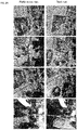
- the reference run of FIG. 2A comprises an example of the regions of each frame.
- Each region may be a rectangular region of same or similar size as each other region.
- the feature determination engine 121 may determine a subset of sparse local features for each region.
- the feature determination engine 121 may determine a sparse local feature based on corner detection in the region. For example, the feature determination engine 121 may identify corners in the region based on corner detection and may select the identified corners as distinctive locations in the region. In some examples, the feature determination engine 121 may perform corner detection by identifying a location based on curvature of the gradient of the frame. For example, the feature determination engine 121 may identify a location responsive to the curvature exceeding a predetermined curvature threshold. In FIGS. 2A and 2B , locations (and corresponding sparse local features) may be depicted by the dots at the corners of objects identified in the various regions shown.
- the feature determination engine 121 may create a sparse local feature for the location by creating a rich feature descriptor for the identified location.
- the rich feature descriptor may comprise information including a gradient distribution around the feature, depth information, feature type(s), size, location of the feature in the region of the frame, a corresponding object identifier that may be associated with the feature, information from the first SLAM map related to the feature and the identified location, and/or any other information related to the feature.
- the rich feature descriptor may also comprise, for example, an n-dimensional vector that represents a pixel patch for the location.
- the amount of data stored in the n-dimensional vector for the sparse local feature should comprise enough information such that the feature can be identified from different viewpoints in different frames of the initial 3D scene.
- the n-dimensional vector may be a 128 dimensional vector, with each dimension representing a different type of information about the sparse local feature, and the pixel patch may comprise a 16x16 pixel patch. These dimensions are purely examples and in no way limit the other sizes that the vector and the pixel patch could have.
- the feature may comprise a robust invariant feature (e.g., Ordinal Spatial Intensity Distribution (OSID) features), where the robust invariant feature may comprise the rich feature descriptor.
- OSID Ordinal Spatial Intensity Distribution
- a sparse local feature may be dependent on the region and the viewpoint of the camera in that region. As such, the sparse local feature may be independent of what the feature looks like in another perspective or viewpoint.
- each region of the set of distinctive frames may have a different curvature threshold associated with it, such that the feature determination engine 121 may perform comer detection in a first region with a first curvature threshold, and may perform corner detection in a second region with a second curvature threshold. Given that, the feature determination engine 121 may identify a location as a sparse local feature in the first region that may or may not be identified as a sparse local feature in the second region.
- the curvature threshold for a region may be machine learned based on multiple frames of the initial 3D scene. In some examples, the curvature threshold for a region may be raised or lowered based on a number of locations initially identified by the feature determination engine 121.
- Feature determination engine 121 may determine a second set of sparse local features from a second set of frames of the current 3D scene in a manner similar to or the same as the determination of the first set of sparse local features of the initial 3D scene.
- Feature determination engine 121 may store information related to the initial 3D scene, current 3D scene, first set of sparse local features, second set of sparse local features, generated SLAM maps, and/or other information accessed, generated, or determined by feature determination engine 121. Feature determination engine 121 may store this information in data storage 120.
- 3D object determination engine 122 may identify a set of objects in the initial 3D scene.
- An object may comprise, for example, an object that may identified by a person viewing the frame.
- the 3D object determination engine 122 may identify objects based on a collection of a subset of the first set of distinctive locations and corresponding set of sparse local features in a region.
- the identified object may comprise a subset of sparse local features in the region that relate to a collection of pixels in the set of distinctive frames of the initial 3D scene that are different from a background of the set of distinctive frames by a predetermined threshold.
- the 3D object determination engine 122 may raise or lower the threshold based on a comparison of a ratio of the number of objects identified and a number of features in the first set of sparse local features.
- the 3D object determination engine 122 may also determine a 3D position for each object within each region for the initial 3D scene. For example, the 3D object determination engine 122 may determine the 3D position based on tracking the sparse local features associated with the object across multiple sequential frames in the initial 3D scene to determine the position of the object relative to other features identified in the region. For example, 3D object determination engine 122 may track a viewpoint of the object within the initial 3D scene using the set of distinctive frames and the first set of sparse local features.
- 3D object determination engine 122 may also track a relative camera position for each frame of the set of distinctive frames and may update the relative camera position for each frame with respect to preceding frames of the set of distinctive frames based on the tracked viewpoint of the object. In these examples, 3D object determination engine 122 may localize a camera position of the current frame of the initial 3D scene based on relative camera positions of each frame of the set of distinctive frames, the first set of sparse local features, and preceding frames of the initial 3D scene.
- 3D object determination engine 122 may determine appearance, disappearance, or movement of an object from the initial 3D scene to the current 3D scene. For example, 3D object determination engine 122 may determine appearance, disappearance, or movement of an object from the initial 3D scene to the current 3D scene based on the determined set of objects of the initial 3D scene and the determined second set of objects of the current 3D scene. In particular, the 3D object determination engine 122 may determine appearance, disappearance, or movement of an object from the initial 3D scene to the current 3D scene responsive to a first sparse local feature of the current set of sparse local features not appearing in the current 3D scene or a new sparse local feature not in the current set of sparse local features appearing in the current 3D scene.
- 3D object determination engine 122 may transform each region of the set of current regions of the current 3D scene to a viewpoint of a corresponding region of the initial 3D scene. For example, the 3D object determination engine 122 may transform the regions of the current set of regions to the viewpoint of the regions of the initial 3D scene based on depth information obtained from the regions. 3D object determination engine 122 may obtain this depth information from the generated SLAM map for the initial 3D scene and the generated SLAM map for the current 3D scene. In some examples, the 3D object determination engine 122 may obtain the depth information for the corresponding regions from the first set of sparse local features of the initial 3D scene and the second set of sparse local features of the current 3D scene.
- 3D object determination engine 122 may compare a first current region of the current region to a corresponding initial region of the set of regions from the initial 3D scene. 3D object determination engine 122 may estimate change from the initial 3D scene to the current 3D scene based on the comparison of the first current region and the corresponding initial region. For example, FIG. 2B may depict the first set of regions of the initial 3D scene as the "Reference run” and the changes detected from each region of the initial 3D scene and a corresponding region of the current 3D scene as the "Changes". The 3D object determination engine 122 may estimate the change by determining appearance, disappearance, or movement of an object based on the comparison of each region of the initial 3D scene and a corresponding region of the current 3D scene.
- 3D object determination engine 122 may determine which of the first set of sparse local features are expected to appear in the first current region. 3D object determination engine 122 may determine which of the expected first set of sparse local features match features in the second set of sparse local features determined for the first current region. 3D object determination engine 122 may determine whether a number of matching features exceeds a predetermined threshold.
- the 3D object determination engine 122 may compare the number of expected features that matched to a number of features in the second set of sparse local features that were not found and/or to a number of features in the first set of sparse local features that were not found in the first current region.
- the 3D object determination engine 122 may determine objects from the first set of objects of the initial 3D scene and/or the second set of objects of the current 3D scene that are associated with these unmatched or missing features.
- the 3D object determination engine 122 may use robust feature matching and/or normalized cross-correlation to compare the first current region and the corresponding initial region. For example, the 3D object determination engine 122 may perform the comparison by comparing a first vector comprising information about the corresponding initial region and a second vector comprising information about the first current region. Responsive to the vector associated with first current region having high variance, the vector for the first current region may be revised to take into account the high variance. In some examples, the 3D object determination engine 122 may revise each vector to have zero mean and unit variance before the vectors are matched. In some examples, 3D object determination engine 122 may remove brightness and contrast from the vectors, but may leave depth and texture information.
- the 3D object determination engine 122 may use normalized cross-correlation responsive to determining that a high confidence in the appearance, disappearance, or movement of objects is needed, and may use robust feature matching to alleviate concerns about viewpoint variations. In some examples, the 3D object determination engine 122 may use both robust feature matching and normalized cross-correlation and may compare the results of each to determine appearance, disappearance, or movement of an object.
- the 3D object determination engine 122 may determine whether depth information is available from the second set of sparse local features in the first current region. The 3D object determination engine 122 may determine that depth information is available from sparse local features in the first current region. Responsive to determining that the depth information is available, 3D object determination engine 122 may use the depth information to determine a patch in the set of distinctive frames of the initial scene that corresponds to the first current region and may compare the determined patch to the first current frame to determine appearance, disappearance, or movement of an object.
- 3D object determination engine 122 may determine whether depth information is available from a set of current neighbor regions (e.g., a 4-neighborhood, 9-neighborhood, and/or other configuration of neighborhood regions) that border the first current region. Responsive to determining that depth information is available from the set of neighboring regions, 3D object determination engine 122 may use the depth information to determine a patch in the first set of distinctive frames that corresponds to the first current region. 3D object determination engine 122 may use the depth information from the set of neighboring regions to determine appearance, disappearance, or movement of an object from the patch to the first current region.
- a set of current neighbor regions e.g., a 4-neighborhood, 9-neighborhood, and/or other configuration of neighborhood regions
- 3D object determination engine 122 may compare the first current region with the corresponding initial region of the initial 3D scene based on color information to determine appearance, disappearance, or movement of an object from the initial 3D scene to the current 3D scene.
- 3D object determination engine 122 may store information related to the set of objects, determined camera positions of the objects and frames, changes detected between corresponding regions of the initial 3D scene and the current 3D scene, and/or other information related to the objects accessed, determined, compared, or generated by 3D object determination engine 122 in data storage 120.
- Information providing engine 123 may provide information about changes detected from the initial 3D scene to the current 3D scene.
- information providing engine 123 may provide information about objects that changed (e.g., appeared, disappeared, or moved) from the initial 3D scene to the current 3D scene.
- the information may comprise, for example, a list of objects, information about sparse local features associated with the objects that changed, information about corresponding regions that comprised objects that changed, information about ways in which the changed objects were determined, any combination thereof, and/or other information relating to change detected between the initial 3D scene and the current 3D scene.
- Information providing engine 123 may provide this information via a display screen of the client computing device of change detection system 100, via an automated alert sent via email or other electronic communication method to a user of the client computing device, a user of the change detection system 100, an administrator of the change detection system 100, and/or other entity interested in the change detection system 100.
- Other methods of providing information about the changes detected between the initial 3D scene and the current 3D scene are feasible as well; the methods used are not limited to the examples described herein.
- Data storage 120 may represent any memory accessible to change detection system 100 that can be used to store and retrieve data.
- Data storage 120 and/or other databases communicably coupled to change detection system 100 may comprise random access memory (RAM), read-only memory (ROM), electrically-erasable programmable read-only memory (EEPROM), cache memory, floppy disks, hard disks, optical disks, tapes, solid state drives, flash drives, portable compact disks, and/or other storage media for storing computer-executable instructions and/or data.
- Change detection system 100 may access data storage 120 locally or remotely via a network.
- Data storage 120 may include a database to organize and store data.
- the database may reside in a single or multiple physical device(s) and in a single or multiple physical location(s).
- the database may store a plurality of types of data and/or files and associated data or file description, administrative information, or any other data.
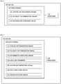
- FIG. 2 is a block diagram depicting an example change detection system 200.
- Change detection system 210 may comprise a processor 210, feature determination engine 221, a 3D object identification engine 222, an information providing engine 223, a localization engine 224, a region determination engine 225, a patch matching engine 226, a color matching engine 227, and/or other engines.
- Engines 221-227 represent engines 121-123, respectively.
- FIG. 3 is a block diagram depicting an example machine-readable storage medium 320 comprising instructions executable by a processor for determining change detection.
- engines 121-123 were described as combinations of hardware and programming. Engines 121-123 may be implemented in a number of fashions.
- the programming may be processor executable instructions 321-323 stored on a machine-readable storage medium 320 and the hardware may include a processor 310 for executing those instructions.
- machine-readable storage medium 320 can be said to store program instructions or code that when executed by processor 310 implements change detection system 100 of FIG. 1 .
- the executable program instructions in machine-readable storage medium 320 are depicted as feature determination instructions 321, 3D object determination instructions 322, and information providing instructions 323.
- Instructions 321-323 represent program instructions that, when executed, cause processor 310 to implement engines 121-123, respectively.
- FIG. 4 is a block diagram depicting an example machine-readable storage medium 420 comprising instructions executable by a processor for determining change detection.
- engines 221-227 were described as combinations of hardware and programming. Engines 221-227 may be implemented in a number of fashions.
- the programming may be processor executable instructions 421-427 stored on a machine-readable storage medium 420 and the hardware may include a processor 410 for executing those instructions.
- machine-readable storage medium 420 can be said to store program instructions or code that when executed by processor 410 implements change detection system 200 of FIG. 2 .
- the executable program instructions in machine-readable storage medium 410 are depicted as feature determination instructions 421, 3D object determination instructions 422, information providing instructions 423, localization instructions 424, region determination instructions 425, patch matching instructions 426, and color matching instructions 427.
- Instructions 421-427 represent program instructions that, when executed, cause processor 410 to implement engines 221-227, respectively.
- Machine-readable storage medium 320 may be any electronic, magnetic, optical, or other physical storage device that contains or stores executable instructions.
- machine-readable storage medium 320 (or machine-readable storage medium 420) may be a non-transitory storage medium, where the term "non-transitory" does not encompass transitory propagating signals.
- Machine-readable storage medium 320 (or machine-readable storage medium 420) may be implemented in a single device or distributed across devices.
- processor 310 (or processor 410) may represent any number of processors capable of executing instructions stored by machine-readable storage medium 320 (or machine-readable storage medium 420).
- Processor 310 (or processor 410) may be integrated in a single device or distributed across devices.
- machine-readable storage medium 320 (or machine-readable storage medium 420) may be fully or partially integrated in the same device as processor 310 (or processor 410), or it may be separate but accessible to that device and processor 310 (or processor 410).
- the program instructions may be part of an installation package that when installed can be executed by processor 310 (or processor 410) to implement change detection system 100.
- machine-readable storage medium 320 (or machine-readable storage medium 420) may be a portable medium such as a floppy disk, CD, DVD, or flash drive or a memory maintained by a server from which the installation package can be downloaded and installed.
- the program instructions may be part of an application or applications already installed.
- machine-readable storage medium 320 (or machine-readable storage medium 420) may include a hard disk, optical disk, tapes, solid state drives, RAM, ROM, EEPROM, or the like.
- Processor 310 may be at least one central processing unit (CPU), microprocessor, and/or other hardware device suitable for retrieval and execution of instructions stored in machine-readable storage medium 320.
- Processor 310 may fetch, decode, and execute program instructions 321-323, and/or other instructions.
- processor 310 may include at least one electronic circuit comprising a number of electronic components for performing the functionality of at least one of instructions 321-323, and/or other instructions.
- Processor 410 may be at least one central processing unit (CPU), microprocessor, and/or other hardware device suitable for retrieval and execution of instructions stored in machine-readable storage medium 420.
- Processor 410 may fetch, decode, and execute program instructions 421-427, and/or other instructions.
- processor 410 may include at least one electronic circuit comprising a number of electronic components for performing the functionality of at least one of instructions 421-427, and/or other instructions.
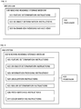
- FIG. 5 is a flow diagram depicting an example method 500 for determining change detection.
- the various processing blocks and/or data flows depicted in FIG. 5 (and in the other drawing figures such as FIGS. 6 & 7 ) are described in greater detail herein.
- the described processing blocks may be accomplished using some or all of the system components described in detail above and, in some implementations, various processing blocks may be performed in different sequences and various processing blocks may be omitted. Additional processing blocks may be performed along with some or all of the processing blocks shown in the depicted flow diagrams. Some processing blocks may be performed simultaneously. Accordingly, the method of FIG. 5 as illustrated (and described in greater detail below) is meant be an example and, as such, should not be viewed as limiting.
- the method of FIG. 5 may be implemented in the form of executable instructions stored on a machine-readable storage medium, such as storage medium 420, and/or in the form of electronic circuitry.
- a first set of sparse local features may be determined from a first set of frames of an initial 3D scene.
- the system 100 (and/or the feature determination engine 121, the feature determination instructions 321, or other resource of the system 100) may determine the first set of sparse local features.
- the system 100 may determine the first set of sparse local features in a manner similar or the same as that described above in relation to the execution of the feature determination engine 121, the feature determination instructions 321, and/or other resource of the system 100.
- FIG. 6 is a flow diagram depicting an example method for determining change detection.
- FIG. 6 shows an example of how to determine the first set of sparse local features (as discussed above with respect to operation 500).
- the method of FIG. 6 as illustrated (and described in greater detail below) is meant to be an example and, as such, should not be viewed as limiting.
- the method of FIG. 6 may be implemented in the form of executable instructions stored on a machine-readable storage medium, such as storage medium 320, and/or in the form of electronic circuitry.
- a set of distinctive frames of the initial 3D scene may be determined from a full set of frames for the initial 3D scene.
- the system 100 (and/or the feature determination engine 121, the feature determination instructions 321, or other resource of the system 100) may determine the set of distinctive frames of the initial 3D scene.
- the system 100 may determine the set of distinctive frames of the initial 3D scene in a manner similar or the same as that described above in relation to the execution of the feature determination engine 121, the feature determination instructions 321, and/or other resource of the system 100.
- a first set of sparse local features may be selected that describe a set of distinctive locations with each frame.
- the system 100 and/or the feature determination engine 121, the feature determination instructions 321, or other resource of the system 100
- the system 100 may select the first set of sparse local features in a manner similar or the same as that described above in relation to the execution of the feature determination engine 121, the feature determination instructions 321, and/or other resource of the system 100.
- a viewpoint of a 3D object within the current 3D scene may be tracked using the set of distinctive frames and the first set of sparse local features.
- the system 100 (and/or the feature determination engine 121, the feature determination instructions 321, or other resource of the system 100) may track the viewpoint of the 3D object within the current 3D scene.
- the system 100 may track the viewpoint of the 3D object within the current 3D scene in a manner similar or the same as that described above in relation to the execution of the feature determination engine 121, the feature determination instructions 321, and/or other resource of the system 100.
- a relative camera position for each frame of the set of distinctive frames may be updated with respect to preceding frames of the set of distinctive frames based on the tracked viewpoint of the 3D object.
- the system 100 (and/or the feature determination engine 121, the feature determination instructions 321, or other resource of the system 100) may update the relative camera position for each frame of the set of distinctive frames.
- the system 100 may update the relative camera position for each frame of the set of distinctive frames in a manner similar or the same as that described above in relation to the execution of the feature determination engine 121, the feature determination instructions 321, and/or other resource of the system 100.
- a current frame of a current 3D scene may be localized relative to the initial 3D scene.
- the system 100 (and/or the feature determination engine 121, the feature determination instructions 321, or other resource of the system 100) may localize the current frame of the current 3D scene relative to the initial 3D scene.
- the system 100 may localize the current frame of the current 3D scene relative to the initial 3D scene in a manner similar or the same as that described above in relation to the execution of the feature determination engine 121, the feature determination instructions 321, and/or other resource of the system 100.
- appearance, disappearance, or movement of an object from the initial 3D scene to the current 3D scene may be determined based on the first set of sparse local features.
- the system 100 (and/or the 3D object determination engine 122, the 3D object determination instructions 322, or other resource of the system 100) may determine appearance, disappearance, or movement of an object from the initial 3D scene to the current 3D scene.
- the system 100 may determine appearance, disappearance, or movement of an object from the initial 3D scene to the current 3D scene in a manner similar or the same as that described above in relation to the execution of the 3D object determination engine 122, the 3D object determination instructions 322, and/or other resource of the system 100.
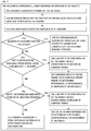
- FIG. 7 is a flow diagram depicting an example method for determining change detection.
- FIG. 7 shows an example of how to determine the appearance, disappearance, or movement of objects (as discussed above with respect to operation 520).
- the method of FIG. 7 as illustrated (and described in greater detail below) is meant to be an example and, as such, should not be viewed as limiting.
- the method of FIG. 7 may be implemented in the form of executable instructions stored on a machine-readable storage medium, such as storage medium 420, and/or in the form of electronic circuitry.
- each frame of the 3D video may be divided into a set of regions, and the operations following operation 705 may be performed for each region of the frame of the 3D video.
- the system 200 (and/or region determination engine 225, the region determination instructions 425, or other resource of the system 200) may divide the frame into the set of regions.
- the system 200 may divide the frame into the set of regions in a manner similar or the same as that described above in relation to the execution of the region determination engine 225, the region determination instructions 425, and/or other resource of the system 200.
- a determination may be made as to which of the first set of sparse local features are expected to appear in the region.
- the system 200 (and/or 3D object determination engine 222, the 3D object determination instructions 422, or other resource of the system 200) may determine which of the first set of sparse local features are expected to appear in the region.
- the system 200 may determine which of the first set of sparse local features are expected to appear in the region in a manner similar or the same as that described above in relation to the execution of the 3D object determination engine 222, the 3D object determination instructions 422, and/or other resource of the system 200.
- matches of expected features may be found in the region.
- the system 200 (and/or 3D object determination engine 222, the 3D object determination instructions 422, or other resource of the system 200) may find matches of expected features in the region.
- the system 200 may find matches of expected features in the region in a manner similar or the same as that described above in relation to the execution of the 3D object determination engine 222, the 3D object determination instructions 422, and/or other resource of the system 200.
- a determination may be made as to whether the number of matches exceeds a predetermined threshold.
- the system 200 and/or 3D object determination engine 222, the 3D object determination instructions 422, or other resource of the system 200 may determine whether the number of matches exceeds the predetermined threshold.
- the system 200 may determine whether the number of matches exceeds the predetermined threshold in a manner similar or the same as that described above in relation to the execution of the 3D object determination engine 222, the 3D object determination instructions 422, and/or other resource of the system 200.
- a comparison of the number of expected features found to the number of unexpected features and missing features may be made.
- the system 200 (and/or 3D object determination engine 222, the 3D object determination instructions 422, or other resource of the system 200) may compare the number of expected features.
- the system 200 may determine the first set of sparse local features in a manner similar or the same as that described above in relation to the execution of the 3D object determination engine 222, the 3D object determination instructions 422, and/or other resource of the system 200.
- a determination may be made as to whether depth information is available from the sparse local features in the region.
- the system 200 and/or patch matching engine 226, the patch matching instructions 426, or other resource of the system 200
- the system 200 may determine whether depth information is available from the sparse local features in the region in a manner similar or the same as that described above in relation to the execution of the patch matching engine 226, the patch matching instructions 426, and/or other resource of the system 200.
- the depth information may be used to find a patch in the reference frame that corresponds to the region in the current frame.
- the system 200 (and/or patch matching engine 226, the patch matching instructions 426, or other resource of the system 200) may find a patch in the reference frame that corresponds to the region in the current frame.
- the system 200 may find a patch in the reference frame that corresponds to the region in the current frame in a manner similar or the same as that described above in relation to the execution of the patch matching engine 226, the patch matching instructions 426, and/or other resource of the system 200.
- the patch in the initial region may be compared to a region in the current frame to determine appearance, disappearance, or movement of an object.
- the system 200 and/or patch matching engine 226, the patch matching instructions 426, 3D object determination engine 222, 3D object determination instructions 422, or other resource of the system 200 may compare the patch in the initial region to a region in the current frame to determine appearance, disappearance, or movement of an object.
- the system 200 may compare the patch in the initial region to a region in the current frame to determine appearance, disappearance, or movement of an object may be compared to determine whether an object appeared, disappeared, or moved in a manner similar or the same as that described above in relation to the execution of the patch matching engine 226, the patch matching instructions 426, 3D object determination engine 222, 3D object determination instructions 422, and/or other resource of the system 200.
- a determination may be made as to whether depth information is available from a set of neighbor regions that border the region.
- the system 200 (and/or patch matching engine 226, the patch matching instructions 426, or other resource of the system 200) may determine whether depth information is available from a set of neighbor regions that border the region.
- the system 200 may determine whether depth information is available from a set of neighbor regions that border the region in a manner similar or the same as that described above in relation to the execution of the patch matching engine 226, the patch matching instructions 426, and/or other resource of the system 200.
- the depth information is used to find a patch in the initial frame that corresponds to the region in the current frame.
- the system 200 and/or patch matching engine 226, the patch matching instructions 426, or other resource of the system 200
- the system 200 may use depth information to find a patch in the initial frame that corresponds to the region in the current frame in a manner similar or the same as that described above in relation to the execution of the patch matching engine 226, the patch matching instructions 426, and/or other resource of the system 200.
- the depth information from the set of neighboring regions is used to determine appearance, disappearance, or movement of an object.
- the system 200 and/or patch matching engine 226, the patch matching instructions 426, 3D object determination engine 222, 3D object determination instructions 422, or other resource of the system 200
- the system 200 may use neighbor information to determine appearance, disappearance, or movement of an object in a manner similar or the same as that described above in relation to the execution of the patch matching engine 226, the patch matching instructions 426, 3D object determination engine 222, 3D object determination instructions 422, and/or other resource of the system 100.
- the region may be compared with a corresponding region in the second 3D video based on color information to determine appearance, disappearance, or movement of an object.
- the system 200 and/or color matching engine 227, the color matching instructions 427, 3D object determination engine 222, 3D object determination instructions 422, and/or other resource of the system 200 may compare the region with the corresponding region in the second 3D video based on color information to determine appearance, disappearance, or movement of the object.
- the system 200 may compare the region with the corresponding region in the second 3D video based on color information to determine appearance, disappearance, or movement of the object in a manner similar or the same as that described above in relation to the execution of the color matching engine 227, the color matching instructions 427, 3D object determination engine 222, 3D object determination instructions 422, and/or other resource of the system 200.
- the foregoing disclosure describes a number of example implementations for change detection.
- the disclosed examples may include systems, devices, computer-readable storage media, and methods for change detection.
- certain examples are described with reference to the components illustrated in FIGS. 1-7 .
- the functionality of the illustrated components may overlap, however, and may be present in a fewer or greater number of elements and components.
Landscapes
- Engineering & Computer Science (AREA)
- Physics & Mathematics (AREA)
- General Physics & Mathematics (AREA)
- Theoretical Computer Science (AREA)
- Computer Vision & Pattern Recognition (AREA)
- Multimedia (AREA)
- Image Analysis (AREA)
Claims (9)
- Verfahren zum Erkennen von Veränderungen in einer dreidimensionalen Ansicht (3D-Ansicht), wobei das Verfahren Folgendes umfasst:Bestimmen (500) eines ersten Satzes spärlicher lokaler Merkmale aus einem ersten Satz von Rahmen einer anfänglichen 3D-Szene;Lokalisieren (510) eines aktuellen Rahmens einer aktuellen 3D-Szene relativ zu der anfänglichen 3D-Szene;wobei die aktuelle 3D-Szene zu einem späteren Zeitpunkt als die anfängliche 3D-Szene auftritt; undBestimmen (520, 710, 712, 715, 720) des Auftretens, Verschwindens oder der Bewegung eines Objekts von der anfänglichen 3D-Szene zu der aktuellen 3D-Szene auf der Grundlage des ersten Satzes spärlicher lokaler Merkmale, dadurch gekennzeichnet, dass das Verfahren ferner Folgendes umfasst:
Bestimmen des ersten Satzes spärlicher lokaler Merkmale, das Folgendes umfasst:Bestimmen (610) eines Satzes unterscheidender Rahmen der anfänglichen 3D-Szene aus einem vollständigen Satz von Rahmen für die anfängliche 3D-Szene;Auswählen (620) des ersten Satzes von spärlichen lokalen Merkmalen, die einen Satz von unterscheidenden Positionen innerhalb jedes Rahmens beschreiben;Verfolgen (630) eines Blickpunkts des Objekts innerhalb der anfänglichen 3D-Szene unter Verwendung des Satzes von unterscheidenden Rahmen und des ersten Satzes von spärlichen lokalen Merkmalen; undAktualisieren (640) einer relativen Kameraposition für jeden Rahmen des Satzes unterscheidender Rahmen in Bezug auf vorhergehende Rahmen des Satzes unterscheidender Rahmen auf der Grundlage des verfolgten Blickpunkts des Objekts, wobei das Verfahren ferner das Bestimmen umfasst, ob sich die aktuelle 3D-Szene von der anfänglichen 3D-Szene unterscheidet, umfassend:Teilen (705) des aktuellen Rahmens in einen Satz aktueller Bereiche;Verändern (730) eines ersten aktuellen Bereichs des Satzes aktueller Bereiche zu einem Blickpunkt des Satzes unterscheidender Rahmen der anfänglichen 3D-Szene unter Verwendung von Tiefeninformationen aus der aktuellen 3D-Szene;Vergleichen (735) des ersten aktuellen Bereichs aus dem Satz aktueller Bereiche mit einem entsprechenden Bereich des Satzes unterscheidender Rahmen; undVerwenden des Bereichsvergleichs zum Schätzen der Änderung von der anfänglichen 3D-Szene zur aktuellen 3D-Szene. - Verfahren nach Anspruch 1, ferner umfassend:
Lokalisieren einer Kameraposition des aktuellen Rahmens der aktuellen 3D-Szene relativ zur anfänglichen 3D-Szene auf der Grundlage von relativen Kamerapositionen jedes Rahmens des Satzes von unterscheidenden Rahmen, von dem ersten Satz spärlicher lokaler Merkmale und von den vorhergehenden Rahmen der aktuellen 3D-Szene. - Verfahren nach einem der vorhergehenden Ansprüche, wobei das Bestimmen, ob sich die aktuelle 3D-Szene von der anfänglichen 3D-Szene unterscheidet, Folgendes umfasst:Bestimmen (710) eines aktuellen Satzes von spärlichen lokalen Merkmalen, von welchen erwartet wird, dass sie in der aktuellen 3D-Szene erscheinen;Bestimmen (720), dass sich die aktuelle 3D-Szene von der anfänglichen 3D-Szene unterscheidet, als Reaktion auf ein erstes spärliches lokales Merkmal des aktuellen Satzes spärlicher lokaler Merkmale, die nicht in der aktuellen 3D-Szene erscheinen, oder auf ein neues spärliches lokales Merkmal, das nicht in dem aktuellen Satz von spärlichen lokalen Merkmalen ist, die in der aktuellen 3D-Szene erscheinen.
- Verfahren nach Anspruch 1, ferner umfassend:als Reaktion auf das Bestimmen (725), dass keine Tiefeninformation für den ersten aktuellen Bereich der aktuellen 3D-Szene vorhanden ist, Verwenden (745) von Tiefeninformation aus benachbarten aktuellen Bereichen des ersten aktuellen Bereichs, um einen zweiten 3D-Rahmen in einen Referenzblickpunkt der ersten 3D-Szene zu verändern; undVergleichen der veränderten aktuellen 3D-Szene und der anfänglichen 3D-Szene.
- Verfahren nach Anspruch 4, ferner umfassend:als Reaktion auf das Bestimmen (740), dass der erste aktuelle Bereich und die benachbarten aktuellen Bereiche keine Tiefeninformationen umfassen, Extrahieren von Farbinformationen des Satzes aktueller Bereiche der aktuellen 3D-Szene; undBestimmen, ob sich die anfängliche 3D-Szene von der aktuellen 3D-Szene unterscheidet, durch Vergleichen (755) der extrahierten Farbinformationen des Satzes aktueller Regionen der aktuellen 3D-Szene mit Farbinformationen aus einem Satz von Regionen der anfänglichen 3D-Szene.
- Verfahren nach einem der vorhergehenden Ansprüche, ferner umfassend:
Empfangen der anfänglichen 3D-Szene oder der aktuellen 3D-Szene von einer Mobiltelefonkamera. - Verfahren nach einem der vorhergehenden Ansprüche, ferner umfassend:Empfangen eines ersten Stereo-Feeds von einer ersten Kamera und eines zweiten Stereo-Feeds von einer zweiten Kamera; undBestimmen der anfänglichen 3D-Szene auf der Grundlage des ersten Stereo-Feeds, des zweiten Stereo-Feeds und von Tiefeninformationen, die auf der Grundlage des ersten Stereo-Feeds und des zweiten Stereo-Feeds bestimmt wurden.
- Maschinenlesbares Speichermedium, umfassend Anweisungen, die von einem Prozessor (110, 210, 310, 410) einer Rechenvorrichtung zum Erfassen einer Änderung in einer dreidimensionalen Ansicht (3D-Ansicht) ausgeführt werden können, wobei das maschinenlesbare Speichermedium Anweisungen zum Implementieren eines Verfahrens nach einem der Ansprüche 1 bis 7 umfasst.
- System (100, 200, 300, 400) zum Erfassen einer Änderung in einer dreidimensionalen Ansicht (3D-Ansicht), umfassend:
einen Prozessor (110, 210, 310, 410), der bewirkt, dass das System ein Verfahren nach einem der Ansprüche 1 bis 7 ausführt.
Applications Claiming Priority (1)
| Application Number | Priority Date | Filing Date | Title |
|---|---|---|---|
| US15/270,180 US10235572B2 (en) | 2016-09-20 | 2016-09-20 | Detecting changes in 3D scenes |
Publications (2)
| Publication Number | Publication Date |
|---|---|
| EP3296958A1 EP3296958A1 (de) | 2018-03-21 |
| EP3296958B1 true EP3296958B1 (de) | 2019-08-21 |
Family
ID=59846386
Family Applications (1)
| Application Number | Title | Priority Date | Filing Date |
|---|---|---|---|
| EP17189703.6A Active EP3296958B1 (de) | 2016-09-20 | 2017-09-06 | Detektion der veränderung in einer dreidimensionalen ansicht |
Country Status (2)
| Country | Link |
|---|---|
| US (1) | US10235572B2 (de) |
| EP (1) | EP3296958B1 (de) |
Families Citing this family (12)
| Publication number | Priority date | Publication date | Assignee | Title |
|---|---|---|---|---|
| US10162362B2 (en) | 2016-08-29 | 2018-12-25 | PerceptIn, Inc. | Fault tolerance to provide robust tracking for autonomous positional awareness |
| US10402663B1 (en) | 2016-08-29 | 2019-09-03 | Trifo, Inc. | Visual-inertial positional awareness for autonomous and non-autonomous mapping |
| US10453213B2 (en) | 2016-08-29 | 2019-10-22 | Trifo, Inc. | Mapping optimization in autonomous and non-autonomous platforms |
| US11314262B2 (en) | 2016-08-29 | 2022-04-26 | Trifo, Inc. | Autonomous platform guidance systems with task planning and obstacle avoidance |
| US10395117B1 (en) | 2016-08-29 | 2019-08-27 | Trifo, Inc. | Visual-inertial positional awareness for autonomous and non-autonomous tracking |
| US10043076B1 (en) | 2016-08-29 | 2018-08-07 | PerceptIn, Inc. | Visual-inertial positional awareness for autonomous and non-autonomous tracking |
| US10311312B2 (en) * | 2017-08-31 | 2019-06-04 | TuSimple | System and method for vehicle occlusion detection |
| US10444761B2 (en) | 2017-06-14 | 2019-10-15 | Trifo, Inc. | Monocular modes for autonomous platform guidance systems with auxiliary sensors |
| US10783381B2 (en) | 2017-08-31 | 2020-09-22 | Tusimple, Inc. | System and method for vehicle occlusion detection |
| US11774983B1 (en) | 2019-01-02 | 2023-10-03 | Trifo, Inc. | Autonomous platform guidance systems with unknown environment mapping |
| CN114895885B (zh) * | 2022-05-20 | 2023-08-15 | 杭州宏深科技有限公司 | 在三维检测软件基于特征的重计算方法 |
| WO2024106223A1 (ja) * | 2022-11-16 | 2024-05-23 | パナソニックIpマネジメント株式会社 | 撮影装置、撮影作業支援方法、および撮影作業支援プログラム |
Family Cites Families (13)
| Publication number | Priority date | Publication date | Assignee | Title |
|---|---|---|---|---|
| JP3512992B2 (ja) * | 1997-01-07 | 2004-03-31 | 株式会社東芝 | 画像処理装置および画像処理方法 |
| US7167576B2 (en) * | 2001-07-02 | 2007-01-23 | Point Grey Research | Method and apparatus for measuring dwell time of objects in an environment |
| US7397929B2 (en) * | 2002-09-05 | 2008-07-08 | Cognex Technology And Investment Corporation | Method and apparatus for monitoring a passageway using 3D images |
| US7391899B2 (en) * | 2005-03-31 | 2008-06-24 | Harris Corporation | System and method for three dimensional change detection and measurement of a scene using change analysis |
| JP5362189B2 (ja) * | 2006-05-10 | 2013-12-11 | 株式会社トプコン | 画像処理装置及びその処理方法 |
| US8049658B1 (en) * | 2007-05-25 | 2011-11-01 | Lockheed Martin Corporation | Determination of the three-dimensional location of a target viewed by a camera |
| US8744133B1 (en) * | 2010-10-04 | 2014-06-03 | The Boeing Company | Methods and systems for locating visible differences on an object |
| US8737685B2 (en) * | 2011-04-25 | 2014-05-27 | Honeywell International Inc. | Systems and methods for detecting the movement of an object |
| US8913791B2 (en) * | 2013-03-28 | 2014-12-16 | International Business Machines Corporation | Automatically determining field of view overlap among multiple cameras |
| US20140369557A1 (en) | 2013-06-14 | 2014-12-18 | Qualcomm Incorporated | Systems and Methods for Feature-Based Tracking |
| WO2015006224A1 (en) | 2013-07-08 | 2015-01-15 | Vangogh Imaging, Inc. | Real-time 3d computer vision processing engine for object recognition, reconstruction, and analysis |
| US9811731B2 (en) | 2013-10-04 | 2017-11-07 | Qualcomm Incorporated | Dynamic extension of map data for object detection and tracking |
| US9619691B2 (en) * | 2014-03-07 | 2017-04-11 | University Of Southern California | Multi-view 3D object recognition from a point cloud and change detection |
-
2016
- 2016-09-20 US US15/270,180 patent/US10235572B2/en active Active
-
2017
- 2017-09-06 EP EP17189703.6A patent/EP3296958B1/de active Active
Non-Patent Citations (1)
| Title |
|---|
| None * |
Also Published As
| Publication number | Publication date |
|---|---|
| US10235572B2 (en) | 2019-03-19 |
| EP3296958A1 (de) | 2018-03-21 |
| US20180082128A1 (en) | 2018-03-22 |
Similar Documents
| Publication | Publication Date | Title |
|---|---|---|
| US10235572B2 (en) | Detecting changes in 3D scenes | |
| US20240169660A1 (en) | Visual localisation | |
| US11051000B2 (en) | Method for calibrating cameras with non-overlapping views | |
| US10580206B2 (en) | Method and apparatus for constructing three-dimensional map | |
| US10628999B2 (en) | Method and apparatus with grid-based plane estimation | |
| US20120163672A1 (en) | Depth Estimate Determination, Systems and Methods | |
| US20190019030A1 (en) | Imaging system and method for object detection and localization | |
| EP3335153B1 (de) | Verwaltung von merkmalsdaten für umgebungsabbildung auf einer elektronischen vorrichtung | |
| WO2016029939A1 (en) | Method and system for determining at least one image feature in at least one image | |
| Peng et al. | Globally-optimal event camera motion estimation | |
| WO2014198351A1 (en) | Method and apparatus for identifying local features | |
| WO2015031855A1 (en) | Expanding a digital representation of a physical plane | |
| US12282984B2 (en) | Augmenting a first image with a second image | |
| US20120033873A1 (en) | Method and device for determining a shape match in three dimensions | |
| Pahwa et al. | Locating 3D object proposals: A depth-based online approach | |
| EP2458559B1 (de) | Markerbeurteilungsvorrichtung, markerbeurteilungs-erkennungssystem, markerbeurteilungs-erkennungsvorrichtung, marker, markerbeurteilungsverfahren und programm dafür | |
| US11361548B2 (en) | Method and system for multi instance visual tracking based on observer motion modelling | |
| US8885952B1 (en) | Method and system for presenting similar photos based on homographies | |
| Cavallari et al. | Semanticfusion: Joint labeling, tracking and mapping | |
| Hashemi et al. | View-independent action recognition: A hybrid approach | |
| Pęszor et al. | Facial reconstruction on the basis of video surveillance system for the purpose of suspect identification | |
| CN111754449B (zh) | 基于光通信装置的场景重构方法和相应的电子设备 | |
| WO2021089107A1 (en) | Image registration based on key-point matching | |
| WO2017042852A1 (en) | Object recognition appratus, object recognition method and storage medium | |
| CN112070175A (zh) | 视觉里程计方法、装置、电子设备及存储介质 |
Legal Events
| Date | Code | Title | Description |
|---|---|---|---|
| PUAI | Public reference made under article 153(3) epc to a published international application that has entered the european phase |
Free format text: ORIGINAL CODE: 0009012 |
|
| STAA | Information on the status of an ep patent application or granted ep patent |
Free format text: STATUS: REQUEST FOR EXAMINATION WAS MADE |
|
| 17P | Request for examination filed |
Effective date: 20170906 |
|
| AK | Designated contracting states |
Kind code of ref document: A1 Designated state(s): AL AT BE BG CH CY CZ DE DK EE ES FI FR GB GR HR HU IE IS IT LI LT LU LV MC MK MT NL NO PL PT RO RS SE SI SK SM TR |
|
| AX | Request for extension of the european patent |
Extension state: BA ME |
|
| GRAP | Despatch of communication of intention to grant a patent |
Free format text: ORIGINAL CODE: EPIDOSNIGR1 |
|
| STAA | Information on the status of an ep patent application or granted ep patent |
Free format text: STATUS: GRANT OF PATENT IS INTENDED |
|
| RAP1 | Party data changed (applicant data changed or rights of an application transferred) |
Owner name: ENTIT SOFTWARE LLC |
|
| INTG | Intention to grant announced |
Effective date: 20190321 |
|
| GRAS | Grant fee paid |
Free format text: ORIGINAL CODE: EPIDOSNIGR3 |
|
| GRAA | (expected) grant |
Free format text: ORIGINAL CODE: 0009210 |
|
| STAA | Information on the status of an ep patent application or granted ep patent |
Free format text: STATUS: THE PATENT HAS BEEN GRANTED |
|
| AK | Designated contracting states |
Kind code of ref document: B1 Designated state(s): AL AT BE BG CH CY CZ DE DK EE ES FI FR GB GR HR HU IE IS IT LI LT LU LV MC MK MT NL NO PL PT RO RS SE SI SK SM TR |
|
| REG | Reference to a national code |
Ref country code: GB Ref legal event code: FG4D |
|
| REG | Reference to a national code |
Ref country code: CH Ref legal event code: EP |
|
| REG | Reference to a national code |
Ref country code: DE Ref legal event code: R096 Ref document number: 602017006297 Country of ref document: DE |
|
| REG | Reference to a national code |
Ref country code: AT Ref legal event code: REF Ref document number: 1170620 Country of ref document: AT Kind code of ref document: T Effective date: 20190915 |
|
| REG | Reference to a national code |
Ref country code: IE Ref legal event code: FG4D |
|
| REG | Reference to a national code |
Ref country code: LT Ref legal event code: MG4D |
|
| REG | Reference to a national code |
Ref country code: NL Ref legal event code: MP Effective date: 20190821 |
|
| PG25 | Lapsed in a contracting state [announced via postgrant information from national office to epo] |
Ref country code: LT Free format text: LAPSE BECAUSE OF FAILURE TO SUBMIT A TRANSLATION OF THE DESCRIPTION OR TO PAY THE FEE WITHIN THE PRESCRIBED TIME-LIMIT Effective date: 20190821 Ref country code: HR Free format text: LAPSE BECAUSE OF FAILURE TO SUBMIT A TRANSLATION OF THE DESCRIPTION OR TO PAY THE FEE WITHIN THE PRESCRIBED TIME-LIMIT Effective date: 20190821 Ref country code: SE Free format text: LAPSE BECAUSE OF FAILURE TO SUBMIT A TRANSLATION OF THE DESCRIPTION OR TO PAY THE FEE WITHIN THE PRESCRIBED TIME-LIMIT Effective date: 20190821 Ref country code: FI Free format text: LAPSE BECAUSE OF FAILURE TO SUBMIT A TRANSLATION OF THE DESCRIPTION OR TO PAY THE FEE WITHIN THE PRESCRIBED TIME-LIMIT Effective date: 20190821 Ref country code: NO Free format text: LAPSE BECAUSE OF FAILURE TO SUBMIT A TRANSLATION OF THE DESCRIPTION OR TO PAY THE FEE WITHIN THE PRESCRIBED TIME-LIMIT Effective date: 20191121 Ref country code: PT Free format text: LAPSE BECAUSE OF FAILURE TO SUBMIT A TRANSLATION OF THE DESCRIPTION OR TO PAY THE FEE WITHIN THE PRESCRIBED TIME-LIMIT Effective date: 20191223 Ref country code: BG Free format text: LAPSE BECAUSE OF FAILURE TO SUBMIT A TRANSLATION OF THE DESCRIPTION OR TO PAY THE FEE WITHIN THE PRESCRIBED TIME-LIMIT Effective date: 20191121 Ref country code: NL Free format text: LAPSE BECAUSE OF FAILURE TO SUBMIT A TRANSLATION OF THE DESCRIPTION OR TO PAY THE FEE WITHIN THE PRESCRIBED TIME-LIMIT Effective date: 20190821 |
|
| PG25 | Lapsed in a contracting state [announced via postgrant information from national office to epo] |
Ref country code: RS Free format text: LAPSE BECAUSE OF FAILURE TO SUBMIT A TRANSLATION OF THE DESCRIPTION OR TO PAY THE FEE WITHIN THE PRESCRIBED TIME-LIMIT Effective date: 20190821 Ref country code: IS Free format text: LAPSE BECAUSE OF FAILURE TO SUBMIT A TRANSLATION OF THE DESCRIPTION OR TO PAY THE FEE WITHIN THE PRESCRIBED TIME-LIMIT Effective date: 20191221 Ref country code: LV Free format text: LAPSE BECAUSE OF FAILURE TO SUBMIT A TRANSLATION OF THE DESCRIPTION OR TO PAY THE FEE WITHIN THE PRESCRIBED TIME-LIMIT Effective date: 20190821 Ref country code: GR Free format text: LAPSE BECAUSE OF FAILURE TO SUBMIT A TRANSLATION OF THE DESCRIPTION OR TO PAY THE FEE WITHIN THE PRESCRIBED TIME-LIMIT Effective date: 20191122 Ref country code: AL Free format text: LAPSE BECAUSE OF FAILURE TO SUBMIT A TRANSLATION OF THE DESCRIPTION OR TO PAY THE FEE WITHIN THE PRESCRIBED TIME-LIMIT Effective date: 20190821 Ref country code: ES Free format text: LAPSE BECAUSE OF FAILURE TO SUBMIT A TRANSLATION OF THE DESCRIPTION OR TO PAY THE FEE WITHIN THE PRESCRIBED TIME-LIMIT Effective date: 20190821 |
|
| REG | Reference to a national code |
Ref country code: AT Ref legal event code: MK05 Ref document number: 1170620 Country of ref document: AT Kind code of ref document: T Effective date: 20190821 |
|
| PG25 | Lapsed in a contracting state [announced via postgrant information from national office to epo] |
Ref country code: TR Free format text: LAPSE BECAUSE OF FAILURE TO SUBMIT A TRANSLATION OF THE DESCRIPTION OR TO PAY THE FEE WITHIN THE PRESCRIBED TIME-LIMIT Effective date: 20190821 |
|
| PG25 | Lapsed in a contracting state [announced via postgrant information from national office to epo] |
Ref country code: DK Free format text: LAPSE BECAUSE OF FAILURE TO SUBMIT A TRANSLATION OF THE DESCRIPTION OR TO PAY THE FEE WITHIN THE PRESCRIBED TIME-LIMIT Effective date: 20190821 Ref country code: AT Free format text: LAPSE BECAUSE OF FAILURE TO SUBMIT A TRANSLATION OF THE DESCRIPTION OR TO PAY THE FEE WITHIN THE PRESCRIBED TIME-LIMIT Effective date: 20190821 Ref country code: PL Free format text: LAPSE BECAUSE OF FAILURE TO SUBMIT A TRANSLATION OF THE DESCRIPTION OR TO PAY THE FEE WITHIN THE PRESCRIBED TIME-LIMIT Effective date: 20190821 Ref country code: RO Free format text: LAPSE BECAUSE OF FAILURE TO SUBMIT A TRANSLATION OF THE DESCRIPTION OR TO PAY THE FEE WITHIN THE PRESCRIBED TIME-LIMIT Effective date: 20190821 Ref country code: IT Free format text: LAPSE BECAUSE OF FAILURE TO SUBMIT A TRANSLATION OF THE DESCRIPTION OR TO PAY THE FEE WITHIN THE PRESCRIBED TIME-LIMIT Effective date: 20190821 Ref country code: EE Free format text: LAPSE BECAUSE OF FAILURE TO SUBMIT A TRANSLATION OF THE DESCRIPTION OR TO PAY THE FEE WITHIN THE PRESCRIBED TIME-LIMIT Effective date: 20190821 |
|
| PG25 | Lapsed in a contracting state [announced via postgrant information from national office to epo] |
Ref country code: SM Free format text: LAPSE BECAUSE OF FAILURE TO SUBMIT A TRANSLATION OF THE DESCRIPTION OR TO PAY THE FEE WITHIN THE PRESCRIBED TIME-LIMIT Effective date: 20190821 Ref country code: CZ Free format text: LAPSE BECAUSE OF FAILURE TO SUBMIT A TRANSLATION OF THE DESCRIPTION OR TO PAY THE FEE WITHIN THE PRESCRIBED TIME-LIMIT Effective date: 20190821 Ref country code: IS Free format text: LAPSE BECAUSE OF FAILURE TO SUBMIT A TRANSLATION OF THE DESCRIPTION OR TO PAY THE FEE WITHIN THE PRESCRIBED TIME-LIMIT Effective date: 20200224 Ref country code: SK Free format text: LAPSE BECAUSE OF FAILURE TO SUBMIT A TRANSLATION OF THE DESCRIPTION OR TO PAY THE FEE WITHIN THE PRESCRIBED TIME-LIMIT Effective date: 20190821 Ref country code: MC Free format text: LAPSE BECAUSE OF FAILURE TO SUBMIT A TRANSLATION OF THE DESCRIPTION OR TO PAY THE FEE WITHIN THE PRESCRIBED TIME-LIMIT Effective date: 20190821 |
|
| REG | Reference to a national code |
Ref country code: DE Ref legal event code: R097 Ref document number: 602017006297 Country of ref document: DE |
|
| PLBE | No opposition filed within time limit |
Free format text: ORIGINAL CODE: 0009261 |
|
| STAA | Information on the status of an ep patent application or granted ep patent |
Free format text: STATUS: NO OPPOSITION FILED WITHIN TIME LIMIT |
|
| PG2D | Information on lapse in contracting state deleted |
Ref country code: IS |
|
| PG25 | Lapsed in a contracting state [announced via postgrant information from national office to epo] |
Ref country code: LU Free format text: LAPSE BECAUSE OF NON-PAYMENT OF DUE FEES Effective date: 20190906 Ref country code: IE Free format text: LAPSE BECAUSE OF NON-PAYMENT OF DUE FEES Effective date: 20190906 |
|
| 26N | No opposition filed |
Effective date: 20200603 |
|
| REG | Reference to a national code |
Ref country code: BE Ref legal event code: MM Effective date: 20190930 |
|
| PG25 | Lapsed in a contracting state [announced via postgrant information from national office to epo] |
Ref country code: SI Free format text: LAPSE BECAUSE OF FAILURE TO SUBMIT A TRANSLATION OF THE DESCRIPTION OR TO PAY THE FEE WITHIN THE PRESCRIBED TIME-LIMIT Effective date: 20190821 Ref country code: BE Free format text: LAPSE BECAUSE OF NON-PAYMENT OF DUE FEES Effective date: 20190930 |
|
| REG | Reference to a national code |
Ref country code: DE Ref legal event code: R082 Ref document number: 602017006297 Country of ref document: DE Representative=s name: BOEHMERT & BOEHMERT ANWALTSPARTNERSCHAFT MBB -, DE Ref country code: DE Ref legal event code: R081 Ref document number: 602017006297 Country of ref document: DE Owner name: MICRO FOCUS LLC (N.D.GES.D.STAATES DELAWARE), , US Free format text: FORMER OWNER: ENTIT SOFTWARE LLC, SUNNYVALE, CALIF., US |
|
| REG | Reference to a national code |
Ref country code: CH Ref legal event code: PL |
|
| PG25 | Lapsed in a contracting state [announced via postgrant information from national office to epo] |
Ref country code: CY Free format text: LAPSE BECAUSE OF FAILURE TO SUBMIT A TRANSLATION OF THE DESCRIPTION OR TO PAY THE FEE WITHIN THE PRESCRIBED TIME-LIMIT Effective date: 20190821 |
|
| PG25 | Lapsed in a contracting state [announced via postgrant information from national office to epo] |
Ref country code: MT Free format text: LAPSE BECAUSE OF FAILURE TO SUBMIT A TRANSLATION OF THE DESCRIPTION OR TO PAY THE FEE WITHIN THE PRESCRIBED TIME-LIMIT Effective date: 20190821 Ref country code: HU Free format text: LAPSE BECAUSE OF FAILURE TO SUBMIT A TRANSLATION OF THE DESCRIPTION OR TO PAY THE FEE WITHIN THE PRESCRIBED TIME-LIMIT; INVALID AB INITIO Effective date: 20170906 |
|
| PG25 | Lapsed in a contracting state [announced via postgrant information from national office to epo] |
Ref country code: LI Free format text: LAPSE BECAUSE OF NON-PAYMENT OF DUE FEES Effective date: 20200930 Ref country code: CH Free format text: LAPSE BECAUSE OF NON-PAYMENT OF DUE FEES Effective date: 20200930 |
|
| PG25 | Lapsed in a contracting state [announced via postgrant information from national office to epo] |
Ref country code: MK Free format text: LAPSE BECAUSE OF FAILURE TO SUBMIT A TRANSLATION OF THE DESCRIPTION OR TO PAY THE FEE WITHIN THE PRESCRIBED TIME-LIMIT Effective date: 20190821 |
|
| PGFP | Annual fee paid to national office [announced via postgrant information from national office to epo] |
Ref country code: DE Payment date: 20250820 Year of fee payment: 9 |
|
| PGFP | Annual fee paid to national office [announced via postgrant information from national office to epo] |
Ref country code: GB Payment date: 20250822 Year of fee payment: 9 |
|
| PGFP | Annual fee paid to national office [announced via postgrant information from national office to epo] |
Ref country code: FR Payment date: 20250821 Year of fee payment: 9 |