EP3296918B1 - Reading device and portable device - Google Patents
Reading device and portable device Download PDFInfo
- Publication number
- EP3296918B1 EP3296918B1 EP17188176.6A EP17188176A EP3296918B1 EP 3296918 B1 EP3296918 B1 EP 3296918B1 EP 17188176 A EP17188176 A EP 17188176A EP 3296918 B1 EP3296918 B1 EP 3296918B1
- Authority
- EP
- European Patent Office
- Prior art keywords
- unit
- read
- reading
- case
- imaging
- Prior art date
- Legal status (The legal status is an assumption and is not a legal conclusion. Google has not performed a legal analysis and makes no representation as to the accuracy of the status listed.)
- Active
Links
Images


Classifications
-
- G—PHYSICS
- G06—COMPUTING OR CALCULATING; COUNTING
- G06K—GRAPHICAL DATA READING; PRESENTATION OF DATA; RECORD CARRIERS; HANDLING RECORD CARRIERS
- G06K7/00—Methods or arrangements for sensing record carriers, e.g. for reading patterns
- G06K7/10—Methods or arrangements for sensing record carriers, e.g. for reading patterns by electromagnetic radiation, e.g. optical sensing; by corpuscular radiation
- G06K7/10009—Methods or arrangements for sensing record carriers, e.g. for reading patterns by electromagnetic radiation, e.g. optical sensing; by corpuscular radiation sensing by radiation using wavelengths larger than 0.1 mm, e.g. radio-waves or microwaves
-
- G—PHYSICS
- G06—COMPUTING OR CALCULATING; COUNTING
- G06K—GRAPHICAL DATA READING; PRESENTATION OF DATA; RECORD CARRIERS; HANDLING RECORD CARRIERS
- G06K7/00—Methods or arrangements for sensing record carriers, e.g. for reading patterns
- G06K7/10—Methods or arrangements for sensing record carriers, e.g. for reading patterns by electromagnetic radiation, e.g. optical sensing; by corpuscular radiation
- G06K7/10544—Methods or arrangements for sensing record carriers, e.g. for reading patterns by electromagnetic radiation, e.g. optical sensing; by corpuscular radiation by scanning of the records by radiation in the optical part of the electromagnetic spectrum
- G06K7/10712—Fixed beam scanning
- G06K7/10722—Photodetector array or CCD scanning
-
- G—PHYSICS
- G06—COMPUTING OR CALCULATING; COUNTING
- G06K—GRAPHICAL DATA READING; PRESENTATION OF DATA; RECORD CARRIERS; HANDLING RECORD CARRIERS
- G06K7/00—Methods or arrangements for sensing record carriers, e.g. for reading patterns
- G06K7/10—Methods or arrangements for sensing record carriers, e.g. for reading patterns by electromagnetic radiation, e.g. optical sensing; by corpuscular radiation
- G06K7/10544—Methods or arrangements for sensing record carriers, e.g. for reading patterns by electromagnetic radiation, e.g. optical sensing; by corpuscular radiation by scanning of the records by radiation in the optical part of the electromagnetic spectrum
- G06K7/10821—Methods or arrangements for sensing record carriers, e.g. for reading patterns by electromagnetic radiation, e.g. optical sensing; by corpuscular radiation by scanning of the records by radiation in the optical part of the electromagnetic spectrum further details of bar or optical code scanning devices
- G06K7/10861—Methods or arrangements for sensing record carriers, e.g. for reading patterns by electromagnetic radiation, e.g. optical sensing; by corpuscular radiation by scanning of the records by radiation in the optical part of the electromagnetic spectrum further details of bar or optical code scanning devices sensing of data fields affixed to objects or articles, e.g. coded labels
-
- G—PHYSICS
- G06—COMPUTING OR CALCULATING; COUNTING
- G06K—GRAPHICAL DATA READING; PRESENTATION OF DATA; RECORD CARRIERS; HANDLING RECORD CARRIERS
- G06K7/00—Methods or arrangements for sensing record carriers, e.g. for reading patterns
- G06K7/10—Methods or arrangements for sensing record carriers, e.g. for reading patterns by electromagnetic radiation, e.g. optical sensing; by corpuscular radiation
- G06K7/10544—Methods or arrangements for sensing record carriers, e.g. for reading patterns by electromagnetic radiation, e.g. optical sensing; by corpuscular radiation by scanning of the records by radiation in the optical part of the electromagnetic spectrum
- G06K7/10821—Methods or arrangements for sensing record carriers, e.g. for reading patterns by electromagnetic radiation, e.g. optical sensing; by corpuscular radiation by scanning of the records by radiation in the optical part of the electromagnetic spectrum further details of bar or optical code scanning devices
- G06K7/10881—Methods or arrangements for sensing record carriers, e.g. for reading patterns by electromagnetic radiation, e.g. optical sensing; by corpuscular radiation by scanning of the records by radiation in the optical part of the electromagnetic spectrum further details of bar or optical code scanning devices constructional details of hand-held scanners
-
- G—PHYSICS
- G06—COMPUTING OR CALCULATING; COUNTING
- G06K—GRAPHICAL DATA READING; PRESENTATION OF DATA; RECORD CARRIERS; HANDLING RECORD CARRIERS
- G06K7/00—Methods or arrangements for sensing record carriers, e.g. for reading patterns
- G06K7/10—Methods or arrangements for sensing record carriers, e.g. for reading patterns by electromagnetic radiation, e.g. optical sensing; by corpuscular radiation
- G06K7/10544—Methods or arrangements for sensing record carriers, e.g. for reading patterns by electromagnetic radiation, e.g. optical sensing; by corpuscular radiation by scanning of the records by radiation in the optical part of the electromagnetic spectrum
- G06K7/10821—Methods or arrangements for sensing record carriers, e.g. for reading patterns by electromagnetic radiation, e.g. optical sensing; by corpuscular radiation by scanning of the records by radiation in the optical part of the electromagnetic spectrum further details of bar or optical code scanning devices
- G06K7/1092—Methods or arrangements for sensing record carriers, e.g. for reading patterns by electromagnetic radiation, e.g. optical sensing; by corpuscular radiation by scanning of the records by radiation in the optical part of the electromagnetic spectrum further details of bar or optical code scanning devices sensing by means of TV-scanning
-
- G—PHYSICS
- G06—COMPUTING OR CALCULATING; COUNTING
- G06K—GRAPHICAL DATA READING; PRESENTATION OF DATA; RECORD CARRIERS; HANDLING RECORD CARRIERS
- G06K7/00—Methods or arrangements for sensing record carriers, e.g. for reading patterns
- G06K7/10—Methods or arrangements for sensing record carriers, e.g. for reading patterns by electromagnetic radiation, e.g. optical sensing; by corpuscular radiation
- G06K2007/10524—Hand-held scanners
Definitions
- the present invention relates to a reading device, which is to be used for a portable device such as a portable terminal, a mobile phone and the like, and a portable device having the same.
- a reading device that is to be used for a portable device, has a one-dimensional scanner and a two-dimensional scanner and is configured to read information of different labels by the one-dimensional scanner and the two-dimensional scanner has been known (for example, refer to Japanese Patent Application Publication No. 2005-63142A )
- US5763864 discloses a hand held dataform reader for reading 1D and 2D bar codes and matrix dataforms.
- the dataform reader includes a dataform reader module having a laser bar code dataform reading assembly, for reading ID bar codes, and an imaging dataform reading assembly, for reading 2D bar codes and matrix codes.
- the dataform reader module further includes selection and control circuitry for energizing a selected one of the reading assemblies. In operation, the laser reading assembly is energized first.
- the target dataform is a ID bar code
- a decodable signal will be generated and decoding circuitry will decode the target dataform. If a decodable signal is not generated by the laser reading assembly, the selection and control circuitry turns off the laser reading assembly and energizes the imaging dataform reading assembly. If the target dataform is a 2D bar code or matrix dataform, the imaging dataform reading assembly will generate a decodable composite video signal representing the image of the dataform. If the video signal is decodable, the decoding circuitry will decode the target dataform.
- US2003085284 discloses a method and apparatus is disclosed for selectively reading a barcode, symbol, or other indicia by either scanning the barcode with a flying-spot scan, or by imaging the barcode, thereby improving reading performance by tailoring the reading method to the particular item that is being read.
- a flying-spot laser scanning front end and an imaging front end are incorporated in a single device. Data obtained by the selected reading method is decoded and output.
- a common decoder or separate decoders may be used to decode the data from the two front ends.
- a single image sensor may be shared between the flying-spot front end and the imaging front-end, with a limited readout area utilized for laser scanning. The size of the readout area may be adjusted based on detected target proximity.
- Selection of the reading mode may be based on criteria including manual input, the range of the target, or previous failed attempts to read the barcode using either reading method.
- An integrated data reader in a console configuration may include a window having a special area in the corner or elsewhere for collecting data by presentation to the imaging front-end, with the flying-spot front end, with its larger depth of field, being utilized for general scanning through the window.
- US5872354 discloses a hand-held data capture system with interchangeable modules including an autofocusing data file image reader. Several exemplary modules having various features are described.
- the invention teaches an apparatus and method for providing an interchangeable RF module, an interchangeable reflected image reader, two exemplary interchangeable non-scanning laser illuminated bar code reader/RF modules, and three exemplary interchangeable long range CCD reader/RF modules.
- noise filtering means a solid state laser illumination system
- signal processing means and filter
- exposure control and depth of field control means.
- An exemplary autofocusing system adjusts the lens to a position where the intensity change with respect to time or with respect to position is maximized.
- a focusing system employs several signal processing algorithms, including a method whereby the maximum slope of the intensity of the image signal with respect to time or with respect to position is determined. Mathematical operations may be performed by a high performance digital signal coprocessor.
- US2013015242 discloses a tri-optic scanner for checking out merchandise at stores includes first and second barcode scanners, and a third barcode scanner placed back-to-back to the second barcode scanner to face an opposite direction of the second barcode scanner.
- the tri-optic scanner is designed to allow the third barcode scanner to conveniently capture barcodes presented by a customer without a cashier touching barcode carriers that belong to the customer.
- a reading device comprises a reading unit configured to illuminate a light beam towards an object to be read, to receive reflected light thereof and to read information of the object to be read, and an imaging unit configured to capture the object to be read as an image.
- An illumination direction of the light beam from the reading unit and an imaging direction of the imaging unit are set to be same.
- FIGS. 1 to 6 an embodiment in which the present invention is applied to a portable terminal will be described with reference to FIGS. 1 to 6 .
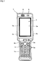
- the portable terminal includes a device case 1.
- the device case 1 has an upper case 2 and a lower case 3.
- the upper case 2 is provided with a display unit 4 and an input unit 5.
- the lower case 3 is provided with a reading device 6 and a battery cover 7.
- the device case 1 has a configuration where a tip end portion-side (an upper part-side in FIG. 1 ) positioned at the display unit 4-side of the upper case 2 and the reading device 6-side of the lower case 3 corresponding to the display unit-side is formed at a rectangular main body part 1a, which is long in a front and rear direction (an upper and lower direction in FIG. 1 ).
- a front side (a lower part-side in FIG. 1 ) positioned at the input unit 5-side of the upper case 2 and the battery cover 7-side of the lower case 3 corresponding to the input unit-side is formed at a rectangular gripping part 1b, which is long in the front and rear direction.
- the device case 1 has a configuration where a length (width) of the gripping part 1b in a direction perpendicular to a longitudinal direction of the device case 1 is shorter than a length (width) of the main body part 1a in the direction perpendicular to the longitudinal direction of the device case 1.
- the device case 1 is entirely formed to have a substantial battledore shape. That is, the device case 1 is formed so that an area of an upper surface of the main body part 1a is greater than an area of an upper surface of the gripping part 1b and the gripping part 1b can be easily gripped.
- the display unit 4 is a planar display panel such as a liquid crystal display panel, an EL (electro luminescence) display panel or the like, and is configured to electro-optically display information. That is, the display unit 4 is arranged in the upper case 2, in correspondence to a display opening 2a formed in the upper case 2.
- the display unit 4 is configured so that the displayed information can be seen through the display opening 2a from AN outside of the upper case 2.
- a part of the upper case 2 positioned at the upper part-side of the display unit 4 is provided with a speaker 8 and a plurality of light emitting elements (LEDs) 9 for indicator.
- LEDs light emitting elements
- the input unit 5 includes diverse keys 5a such as a ten key, a calculation key, a cursor key, a decision key, a power supply key and the like and the keys are aligned on the upper case 2 positioned at the gripping part 1b-side.
- the input unit 5 is configured to input the information as the diverse keys 5a are operated.
- an upper part of the input unit 5 is provided with a center trigger key 5b.
- both side surfaces of the device case 1 are provided with side trigger keys 17b, respectively.
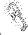
- the reading device 6 is provided on a lower surface (an upper surface in FIG. 3 ) of the lower case 3 corresponding to a back surface-side of the display unit 4.
- the battery cover 7 is provided on the lower surface of the lower case 3 corresponding to a back surface-side of the input unit 5.
- the battery cover 7 is configured to openably and closably block a battery accommodation part provided in the lower case 3 corresponding to the back surface-side of the input unit 5 and configured to accommodate therein a battery.
- the battery cover 7 is formed to have a reverse tub shape having a semicircular section and is configured to cover and block the battery accommodation part in the lower case 3 with a lower part-side (an upper part-side in FIG. 3 ) being convex.
- the battery cover 7 is formed so that when the battery cover 7 is attached to a lower surface (an upper surface in FIG. 3 ) of the lower case 3, the gripping part 1b of the device case 1 can be easily gripped.
- the reading device 6 has a unit case 10.
- the unit case 10 is configured to be detachably attached to a back surface (an upper surface in FIG. 4 ) of the lower case 3 by a plurality of screws 11.
- the unit case 10 is configured so that the reading unit 12 and the imaging unit 13 are provided therein.
- the reading unit 12 is a scanner and is configured to illuminate a light beam such as a laser light beam to an object to be read (not shown), to receive reflected light thereof and to read code information of the object to be read.
- the imaging unit 13 is a camera having an imaging element and is configured to capture the object to be read, which is to be read by the reading unit 20, as an image.
- the object to be read is a label attached to a product, and code information such as a barcode, a two-dimensional code and the like is indicated thereon.
- the code information of the object to be read which is read by the reading unit 12, is displayed on the display unit 4. Also, the image of the object to be read captured by the imaging unit 13 is displayed on the display unit 4. Thereby, it is possible to perform the reading operation by the reading unit 12 and the capturing operation by the imaging unit 13 at the same time while seeing the code information of the object to be read and the image of the object to be read displayed on the display unit 4.
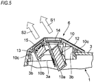
- the unit case 10 is formed by protruding a rectangular plate into a mountain shape gently inclined in the longitudinal direction of the device case 1. As shown in FIG. 5 , the unit case 10 is provided therein with a reading attaching part (a first attaching part) 10a to which the reading unit 12 is attached and an imaging attaching part (a second attaching part) 10b to which the imaging unit 13 is attached.
- a reading attaching part a first attaching part
- an imaging attaching part a second attaching part
- the unit case 10 is provided at an outer periphery thereof with a mounting rim 10c and is attached to the lower case 3 by the plurality of screws 11 at a state where the mounting rim 10c is mounted to a frame-shaped edge 3b of an opening 3a formed in the lower surface (an upper surface in FIG. 4 ) of the lower case 3.
- the unit case 10 is provided with a reading window part 14 corresponding to the reading unit 12 and an imaging window part 15 corresponding to the imaging unit 13.
- the reading unit 12 and the imaging unit 13 are set so that an illumination direction S1 of the light beam from the reading unit 20 and an imaging direction S2 of the imaging unit 21 are the same, as shown in FIG. 5 .
- the reading unit 12 is arranged at a state where the illumination direction S1 of the light beam is inclined relative to the reading window part 14. That is, when the illumination direction S1 of the light beam is orthogonal to the reading window part 14, a part of the light beam illuminated to and penetrating the reading window part 14 is reflected on the reading window part 14. Then, the reflected light beam is received at the reading unit 12. Therefore, the reading unit 12 is arranged with the illumination direction S1 of the light beam being inclined relative to the reading window part 14 so that the light beam reflected on the reading window part 14 is not to be illuminated to the reading unit 12.
- the imaging unit 13 is arranged at a state where the imaging direction S2 is orthogonal to the imaging window part 15. That is, when the imaging direction S2 is inclined relative to the imaging window part 15, the light of the image of the object to be read is refracted at the imaging window part 15, so that the image of the object to be read is read with being distorted. For this reason, the imaging unit 13 is arranged so that the imaging direction S2 is orthogonal to the imaging window part 15.
- the reading window part 14 is provided at one inclined part of the mountain shape of the unit case 10. Also, the imaging window part 15 is provided at the other inclined part of the mountain shape of the unit case 10. That is, the reading window part 14 is provided at the inclined part of the unit case 10 positioned at the gripping part 1b-side. Also, the imaging window part 15 is provided at the inclined part of the unit case 10 positioned at an opposite side to the gripping part 1b.
- the reading unit 12 and the imaging unit 13 are arranged in the unit case 10 at a state where the illumination direction S1 of the light beam from the reading unit 12 and the imaging direction S2 of the imaging unit 13 are inclined relative to the lower surface of the device case 1, i.e., the lower surface of the lower case 3 by a predetermined angle ⁇ .
- the illumination direction S1 of the light beam from the reading unit 12 and the imaging direction S2 of the imaging unit 13 are preferably inclined relative to the lower surface of the lower case 3 within an angle range of 40° to 80°, preferably at an angle of 60° towards a tip end-side (an upper part-side in FIG. 2 ) of the lower case 3 positioned at an opposite side to the gripping part 1b, as shown in FIGS. 2 and 5 .
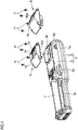
- the reading device 6 has different configurations with respect to code information indicated on the object to be read, for example a barcode and a two-dimensional code. That is, the reading device 6 configured to read a barcode has a configuration where the reading unit 12 and the imaging unit 13 are incorporated in the unit case 10. Also, the reading device 6 configured to read a two-dimensional code has a configuration where only an imaging unit (not shown) is incorporated in the other unit case 16.
- the reading device 6 is configured so that the two types of the unit cases 10, 16 can be replaced. That is, one unit case 10 configured to read a barcode is provided with the reading window part 14 corresponding to the reading unit 12 and the imaging window part 15 corresponding to the imaging unit 13, as described above.
- the other unit case 16 configured to read the two-dimensional code has an outer periphery shape having the same size as the one unit case 10 configured to read a barcode, and is configured to be attached to the lower case 3 by the screws 11, like the one unit case 10.
- the other unit case 16 configured to read a two-dimensional code is configured so that an attachment position to the lower case 3 is the same as an attachment position at which the one unit case 10 configured to read a barcode is to be attached the lower case 3.
- the other unit case 16 configured to read a two-dimensional code is formed to have a mountain shape higher than the one unit case 10 configured to read a barcode and only an imaging window part 16a corresponding to the imaging unit (not shown) is provided at one inclined part of the mountain shape.
- the other unit case 16 configured to read a two-dimensional code is configured so that an imaging direction of the imaging unit is the same as the imaging direction S2 of the one unit case 10 configured to read a barcode, i.e., is inclined relative to the lower surface of the lower case 3, which is the lower surface of the device case 1, by the predetermined angle ⁇ .
- the reading device 6 is configured to read the code information of the object to be read, on which any one of the barcode and the two-dimensional code is indicated, by replacing the one unit case 10 and the other unit case 16 in correspondence to a code type of the object to be read.
- the portable terminal includes a CPU 20, a memory unit 21, the display unit 4, the input unit 5 and the reading device 6.
- the memory unit 21 includes a ROM (read-only memory) and a RAM (random access memory).
- the CPU 20 is configured to perform the entire processing of the portable terminal on the basis of a program stored in the ROM of the memory unit 21.
- a program configured to control the processing that is to be executed by the CPU 20 is stored.
- the display unit 4 is configured to display a variety of information of goods, stocks thereof and the like, in addition to the code information and the image of the object to be read, based on a command from the CPU 20.
- the input unit 5 is configured to input the information of goods, stocks thereof and the like by the diverse keys 5a and to input triggers by the center trigger key 5b and the side trigger keys 5c.
- the reading device 6 includes the reading unit 12 and the imaging unit 13.
- the commands are issued at the same time from the CPU 20, so that the reading unit 12 and the imaging unit 13 are operated. That is, when any one of the center trigger key 5b and the side trigger keys 5c is operated, the reading unit 12 reads the code information of the object to be read such as a label attached to the commercial goods on the basis of the command from the CPU 20 and outputs the read code information to the CPU 20.
- the imaging unit 13 captures the object to be read such as the same label attached to the same commercial goods, as an image, and outputs the captured image to the CPU 20 on the basis of the command from the CPU 20, like the reading unit 12.
- the portable terminal When using the portable terminal, first, an operator grips the gripping part 1b of the device case 1 with a hand with the upper case 2 of the device case 1 facing upwards. At this state, the display unit 4 and the input unit 5 of the upper case 2 face upwards.
- the operator can input information of goods, stocks thereof and the like by operating the diverse keys 5a of the input unit 5 with gripping the gripping part 1b of the device case 1.
- the input information is displayed on the display unit 4, so that the operator can see the information through the display opening 2a of the upper case 2.
- the operator when reading the code information and the image of the object to be read such as a label attached to the commercial goods by the reading device 6, the operator sets the reading window part 14 and the imaging window part 15 of the unit case 10 to face towards the object to be read and operates any one of the center trigger key 5b provided at the upper side part of the input unit 5 and the side trigger keys 5c provided at both sides of the device case 1.
- the reading unit 12 of the reading device 6 reads the code information of the object to be read and the imaging unit 13 captures the object to be read as an image, at the same time.
- the reading unit 12 when the reading unit 12 reads the code information of the object to be read, the reading unit 12 illuminates a light beam such as a laser light beam towards the object to be read, receives the light beam reflected on the object to be read and thus reads the code information of the object to be read.
- the reading unit 12 is arranged at the state where the illumination direction S1 of the light beam is inclined relative to the reading window part 14 provided at the unit case 10.
- the reading unit 12 illuminates the light beam towards the object to be read, even though a part of the light beam illuminated to and penetrating the reading window part 14 is reflected on the reading window part 14, the reflected light beam is not illuminated towards the reading unit 12, so that the light beam reflected on the reading window part 14 is not illuminated to the reading unit 12. Thereby, the code information of the object to be read is accurately read by the reading unit 12.
- the imaging unit 13 when the imaging unit 13 reads the object to be read as an image, the image of the object to be read is read through the imaging window part 15 of the unit case 10 by the imaging unit 13.
- the imaging unit 13 is arranged so that the imaging direction S2 is orthogonal to the imaging window part 15. For this reason, the light of the image of the object to be read is refracted at the imaging window part 15 and the image of the object to be read is not distorted, so that the imaging unit 13 can accurately capture the object to be read as an image.
- the code information and the image of the object to be read which have been read by the reading device 6, are displayed on the display unit 4.
- the operator operates the decision key 5a of the input unit 5 while seeing the code information and the image of the object to be read displayed on the display unit 4, so that the code information and the image of the object to be read displayed on the display unit 4 are stored.
- the reading device 6 has different configurations with respect to the code information indicated on the object to be read, for example a barcode and a two-dimensional code. For this reason, when reading the two-dimensional code, the operator detaches the one unit case 10 for reading a barcode from the lower case 3 and attaches the other unit case 16 for reading a two-dimensional code to the lower case 3.
- the other unit case 16 has the mountain shape different from the mountain shape of the one unit case 10 but the attachment positions are the same, so that it is possible to easily replace the other unit case with the one unit case 10. Also, the other unit case 16 is arranged so that the imaging direction thereof faces in the same direction as the imaging direction S2 of the one unit case 10. Thereby, it is possible to easily read the code information of the object to be read, on which the two-dimensional code is indicated, by the reading device 6 of the other unit case 16, like the reading device 6 of the one unit case 10.
- the reading device 6 includes the reading unit 12 configured to illuminate the light beam towards the object to be read, to receive the reflected light and to read the code information of the object to be read and the imaging unit 13 configured to capture the object to be read, as an image, and the illumination direction S1 of the light beam from the reading unit 12 and the imaging direction S2 of the imaging unit 13 are set to be the same. Thereby, when reading the code information and capturing the object to be read, it is not necessary to change a direction of the portable terminal.
- the portable terminal can display the code information and the image of the object to be read, which have been read by the reading device 6, on the display unit 4 at the same time. For this reason, since the operator can see and confirm the code information and the image of the object to be read displayed on the display unit 4, it is possible to accurately and securely read the code information and the image of the object to be read. Thereby, it is possible to easily perform the operation of reading the code information and the image of the object to be read and to improve the reading operability.
- the reading device 6 has the unit case 10 to which the reading unit 12 and the imaging unit 13 are mounted, and the unit case 10 is provided with the reading window part 14 corresponding to the reading unit 12 and the imaging window part 15 corresponding to the imaging unit 13, so that it is possible to securely read the code information of the object to be read through the reading window part 14 of the unit case 10 by the reading unit 12 and to securely capture the object to be read as an image, through the imaging window part 15 of the unit case 10 by the imaging unit 13.
- the reading unit 12 is arranged so that the illumination direction S1 of the light beam is inclined relative to the reading window part 14, and the imaging unit 13 is arranged so that the imaging direction S2 is orthogonal to the imaging window part 15.
- the reading device 6 can accurately and favorably the code information of the object to be read by the reading unit 12 and to accurately and favorably capture the object to be read, as an image, by the imaging unit 13.
- the reading unit 12 is arranged so that the illumination direction S1 of the light beam is inclined relative to the reading window part 14 provided at the unit case 10.
- the reflected light beam is not reflected towards the reading unit 12. For this reason, since the light beam reflected on the reading window part 14 is not illuminated to the reading unit 12, it is possible to accurately and favorably read the code information of the object to be read by the reading unit 12.
- the imaging unit 13 is arranged so that the imaging direction S2 is orthogonal to the imaging window part 15.
- the imaging direction S2 is orthogonal to the imaging window part 15.
- the unit case 10 is formed to have the mountain shape gently inclined in the longitudinal direction of the device case 1, the inclined part positioned at the gripping part 1b-side of the device case 1 is provided with the reading window part 14, and the inclined part positioned at the opposite side to the gripping part 1b of the device case 1 is provided with the imaging window part 15.
- the unit case 10 is detachably attached to the device case 1 by the plurality of screws 11, so that it is possible to easily replace the unit case 10 with the other unit case 16. That is, since the reading device 6 has different configurations with respect to the code information indicated on the object to be read, for example a barcode and a two-dimensional code, when reading the barcode and the two-dimensional code, it is possible to replace the unit cases 10, 16.
- the other unit case 16 configured to read a two-dimensional code has the mountain shape different from the mountain shape of the one unit case 10 configured to read a barcode but the attachment positions are the same, so that it is possible to easily replace the other unit case with the one unit case 10.
- the reading device 6 of the other unit case 16 it is possible to read the code information of the object to be read, on which the two-dimensional code is indicated, by the reading device 6 of the other unit case 16, like the reading device 6 of the one unit case 10.
- the reading device 6 when the two types of the unit cases 10, 16 are replaced in correspondence to the code type of the object to be read, it is possible to select which of the object to be read having a barcode indicated thereon and the object to be read having a two-dimensional code indicated thereon is to be read. Also, the reading device 6 can favorably read the code information of the object to be read, on which any one of the barcode and the two-dimensional code is indicated, by the selected case of the unit cases 10, 16.
- the illumination direction S1 of the light beam from the reading unit 12 and the imaging direction S2 of the imaging unit 13 are inclined relative to the device case 1 by the predetermined angle ⁇ .
- the reading device 6 can securely and favorably read the code information and the image of the object to be read by the reading unit 12 and the imaging unit 13.
- the illumination direction S1 of the light beam from the reading unit 12 and the imaging direction S2 of the imaging unit 13 are inclined relative to the lower surface of the lower case 3 within an angle range of 40° to 80°, preferably at an angle of 60° towards the tip end-side of the device case 1 positioned at the opposite side to the gripping part 1b of the device case 1.
- the reading device 6 has the unit case 10 for reading a barcode and the unit case 16 for reading a two-dimensional code.
- the present invention is not limited thereto.
- three types or more of unit cases configured to be replaceable may be provided.
- the present invention is applied to the portable terminal.
- the present invention can be applied to a portable device such as a mobile phone, a portable information terminal and the like.
Landscapes
- Physics & Mathematics (AREA)
- Engineering & Computer Science (AREA)
- Electromagnetism (AREA)
- Health & Medical Sciences (AREA)
- Toxicology (AREA)
- General Health & Medical Sciences (AREA)
- Artificial Intelligence (AREA)
- Computer Vision & Pattern Recognition (AREA)
- General Physics & Mathematics (AREA)
- Theoretical Computer Science (AREA)
- Image Input (AREA)
- Facsimile Scanning Arrangements (AREA)
Applications Claiming Priority (1)
| Application Number | Priority Date | Filing Date | Title |
|---|---|---|---|
| JP2016179632A JP6623990B2 (ja) | 2016-09-14 | 2016-09-14 | 携帯機器 |
Publications (2)
| Publication Number | Publication Date |
|---|---|
| EP3296918A1 EP3296918A1 (en) | 2018-03-21 |
| EP3296918B1 true EP3296918B1 (en) | 2019-12-18 |
Family
ID=59799217
Family Applications (1)
| Application Number | Title | Priority Date | Filing Date |
|---|---|---|---|
| EP17188176.6A Active EP3296918B1 (en) | 2016-09-14 | 2017-08-28 | Reading device and portable device |
Country Status (4)
| Country | Link |
|---|---|
| US (1) | US10372955B2 (OSRAM) |
| EP (1) | EP3296918B1 (OSRAM) |
| JP (1) | JP6623990B2 (OSRAM) |
| CN (1) | CN107818276B (OSRAM) |
Families Citing this family (2)
| Publication number | Priority date | Publication date | Assignee | Title |
|---|---|---|---|---|
| SG11202100572SA (en) * | 2019-10-10 | 2021-05-28 | Shenzhen Idata Tech Company Ltd | Rfid terminal and method of using the same |
| JP7441064B2 (ja) * | 2020-02-07 | 2024-02-29 | カシオ計算機株式会社 | 携帯情報端末 |
Family Cites Families (29)
| Publication number | Priority date | Publication date | Assignee | Title |
|---|---|---|---|---|
| US5872354A (en) | 1989-01-31 | 1999-02-16 | Norand Corporation | Hand-held data capture system with interchangable modules including autofocusing data file reader using the slope of the image signal to determine focus |
| US5530619A (en) | 1989-06-07 | 1996-06-25 | Norand Corporation | Hand-held data capture system with interchangeable modules and side-mounted function key |
| DE69231057T2 (de) | 1991-02-25 | 2001-02-15 | Intermec Ip Corp., Woodland Hills | Tragbares datenerfassungssystem mit austauschbaren modulen und interaktiven steuerschaltungen |
| JP3187936B2 (ja) * | 1992-05-29 | 2001-07-16 | オリンパス光学工業株式会社 | バーコード読取装置 |
| US5763864A (en) * | 1994-07-26 | 1998-06-09 | Meta Holding Corporation | Dataform reader including dual laser and imaging reading assemblies |
| JPH0991368A (ja) * | 1995-07-20 | 1997-04-04 | Fujitsu Ltd | 光学読取装置 |
| US6811086B1 (en) * | 1995-07-20 | 2004-11-02 | Fujitsu Limited | Stand for pivotably mounting an optical reading device |
| US6575368B1 (en) * | 1996-01-31 | 2003-06-10 | Psc Scanning, Inc. | Multiple aperture data reader for multi-mode operation |
| US5801918A (en) * | 1996-07-12 | 1998-09-01 | Hand Held Products, Inc. | Ergonomic housing for a micro computer |
| US5992744A (en) * | 1997-02-18 | 1999-11-30 | Welch Allyn, Inc. | Optical reader having multiple scanning assemblies with simultaneously decoded outputs |
| US7137555B2 (en) * | 2000-02-28 | 2006-11-21 | Psc Scanning, Inc. | Multi-format bar code reader |
| EP1717728B1 (en) * | 2001-01-22 | 2010-09-01 | Hand Held Products, Inc. | Optical reader having partial frame operating mode |
| US7637430B2 (en) * | 2003-05-12 | 2009-12-29 | Hand Held Products, Inc. | Picture taking optical reader |
| JP4403750B2 (ja) | 2003-08-12 | 2010-01-27 | カシオ計算機株式会社 | コード読取装置 |
| US7334729B2 (en) * | 2006-01-06 | 2008-02-26 | International Business Machines Corporation | Apparatus, system, and method for optical verification of product information |
| US20090159685A1 (en) * | 2007-12-20 | 2009-06-25 | Symbol Technologies, Inc. | Optimizing Optical Quality of a Sensor in a Bar Code Reader |
| JP4546554B2 (ja) * | 2008-04-04 | 2010-09-15 | 東芝テック株式会社 | コードシンボル読取装置 |
| US20090321524A1 (en) * | 2008-06-26 | 2009-12-31 | David Bellows | Method and System for Adapting a Mobile Computing Device with a Face Module Expansion Port |
| US8167207B2 (en) * | 2008-07-15 | 2012-05-01 | Symbol Technologies, Inc. | Integrated optical exit window |
| USD614626S1 (en) * | 2008-11-18 | 2010-04-27 | Inventec Appliances (Shanghai) Co., Ltd. | Hand held device |
| US8587595B2 (en) * | 2009-10-01 | 2013-11-19 | Hand Held Products, Inc. | Low power multi-core decoder system and method |
| CA2744749C (en) * | 2011-06-30 | 2019-09-24 | Imperial Oil Resources Limited | Basal planer gravity drainage |
| US8944322B2 (en) | 2011-07-15 | 2015-02-03 | Wal-Mart Stores, Inc. | Tri-optic scanner |
| US8608071B2 (en) * | 2011-10-17 | 2013-12-17 | Honeywell Scanning And Mobility | Optical indicia reading terminal with two image sensors |
| US9084900B2 (en) * | 2012-06-29 | 2015-07-21 | Boston Scientific Neuromodulation Corporation | Neuromodulation system and method for reducing energy requirements using feedback |
| US9202095B2 (en) * | 2012-07-13 | 2015-12-01 | Symbol Technologies, Llc | Pistol grip adapter for mobile device |
| US9208367B2 (en) * | 2012-11-15 | 2015-12-08 | Hand Held Products | Mobile computer configured to read multiple decodable indicia |
| US10229303B2 (en) * | 2013-12-20 | 2019-03-12 | Cognex Corporation | Image module including mounting and decoder for mobile devices |
| US9928392B2 (en) * | 2014-06-13 | 2018-03-27 | The Code Corporation | Barcode-reading system that obtains ranging data via targeting illumination |
-
2016
- 2016-09-14 JP JP2016179632A patent/JP6623990B2/ja active Active
-
2017
- 2017-08-24 US US15/685,558 patent/US10372955B2/en active Active
- 2017-08-28 EP EP17188176.6A patent/EP3296918B1/en active Active
- 2017-09-07 CN CN201710799580.9A patent/CN107818276B/zh not_active Expired - Fee Related
Non-Patent Citations (1)
| Title |
|---|
| None * |
Also Published As
| Publication number | Publication date |
|---|---|
| CN107818276B (zh) | 2020-12-08 |
| CN107818276A (zh) | 2018-03-20 |
| US10372955B2 (en) | 2019-08-06 |
| JP2018045445A (ja) | 2018-03-22 |
| JP6623990B2 (ja) | 2019-12-25 |
| EP3296918A1 (en) | 2018-03-21 |
| US20180075270A1 (en) | 2018-03-15 |
Similar Documents
| Publication | Publication Date | Title |
|---|---|---|
| US10311274B2 (en) | Reader for optical indicia presented under two or more imaging conditions within a single frame time | |
| US5949057A (en) | Portable data collection device with crosshair targeting illumination assembly | |
| US8910872B2 (en) | Imaging reader and method with dual function illumination light assembly | |
| US6431452B2 (en) | Portable data collection device with variable focusing module for optic assembly | |
| US7854385B2 (en) | Automatic region of interest focusing for an imaging-based bar code reader | |
| CN109902522B (zh) | 具有多个电路板的手持式条形码读取器 | |
| US6609660B1 (en) | Optical device for increasing the apparent resolution of photosensor | |
| EP3709161B1 (en) | Indicia reader with programmable indicators of software upgrades | |
| US12190197B2 (en) | Indicia reader acoustic for multiple mounting positions | |
| US11062102B2 (en) | Decoding indicia with polarized imaging | |
| US6572017B1 (en) | Optical device employing a mirror array for increasing the apparent resolution of a photosensor | |
| EP3296918B1 (en) | Reading device and portable device | |
| CN109424871B (zh) | 用于条码扫描器的照明器 | |
| US20110089244A1 (en) | Electro-optical reader with visible indication of successful decode in line of sight of operator | |
| US9367721B2 (en) | Imaging optical code scanner with camera regions | |
| US20060146171A1 (en) | Imaging scanner | |
| US20250139394A1 (en) | Balancing Decoding Performance and Speed Using One or More Parameters for Decoding Damaged Data Matrix Barcodes | |
| US7854382B2 (en) | Light collection assembly with self-retaining lens in electro-optical reader |
Legal Events
| Date | Code | Title | Description |
|---|---|---|---|
| PUAI | Public reference made under article 153(3) epc to a published international application that has entered the european phase |
Free format text: ORIGINAL CODE: 0009012 |
|
| STAA | Information on the status of an ep patent application or granted ep patent |
Free format text: STATUS: REQUEST FOR EXAMINATION WAS MADE |
|
| 17P | Request for examination filed |
Effective date: 20170828 |
|
| AK | Designated contracting states |
Kind code of ref document: A1 Designated state(s): AL AT BE BG CH CY CZ DE DK EE ES FI FR GB GR HR HU IE IS IT LI LT LU LV MC MK MT NL NO PL PT RO RS SE SI SK SM TR |
|
| AX | Request for extension of the european patent |
Extension state: BA ME |
|
| GRAP | Despatch of communication of intention to grant a patent |
Free format text: ORIGINAL CODE: EPIDOSNIGR1 |
|
| STAA | Information on the status of an ep patent application or granted ep patent |
Free format text: STATUS: GRANT OF PATENT IS INTENDED |
|
| INTG | Intention to grant announced |
Effective date: 20190722 |
|
| GRAS | Grant fee paid |
Free format text: ORIGINAL CODE: EPIDOSNIGR3 |
|
| GRAA | (expected) grant |
Free format text: ORIGINAL CODE: 0009210 |
|
| STAA | Information on the status of an ep patent application or granted ep patent |
Free format text: STATUS: THE PATENT HAS BEEN GRANTED |
|
| AK | Designated contracting states |
Kind code of ref document: B1 Designated state(s): AL AT BE BG CH CY CZ DE DK EE ES FI FR GB GR HR HU IE IS IT LI LT LU LV MC MK MT NL NO PL PT RO RS SE SI SK SM TR |
|
| REG | Reference to a national code |
Ref country code: CH Ref legal event code: EP |
|
| REG | Reference to a national code |
Ref country code: IE Ref legal event code: FG4D |
|
| REG | Reference to a national code |
Ref country code: DE Ref legal event code: R096 Ref document number: 602017009797 Country of ref document: DE |
|
| REG | Reference to a national code |
Ref country code: AT Ref legal event code: REF Ref document number: 1215405 Country of ref document: AT Kind code of ref document: T Effective date: 20200115 |
|
| REG | Reference to a national code |
Ref country code: NL Ref legal event code: MP Effective date: 20191218 |
|
| PG25 | Lapsed in a contracting state [announced via postgrant information from national office to epo] |
Ref country code: GR Free format text: LAPSE BECAUSE OF FAILURE TO SUBMIT A TRANSLATION OF THE DESCRIPTION OR TO PAY THE FEE WITHIN THE PRESCRIBED TIME-LIMIT Effective date: 20200319 Ref country code: NO Free format text: LAPSE BECAUSE OF FAILURE TO SUBMIT A TRANSLATION OF THE DESCRIPTION OR TO PAY THE FEE WITHIN THE PRESCRIBED TIME-LIMIT Effective date: 20200318 Ref country code: LT Free format text: LAPSE BECAUSE OF FAILURE TO SUBMIT A TRANSLATION OF THE DESCRIPTION OR TO PAY THE FEE WITHIN THE PRESCRIBED TIME-LIMIT Effective date: 20191218 Ref country code: LV Free format text: LAPSE BECAUSE OF FAILURE TO SUBMIT A TRANSLATION OF THE DESCRIPTION OR TO PAY THE FEE WITHIN THE PRESCRIBED TIME-LIMIT Effective date: 20191218 Ref country code: SE Free format text: LAPSE BECAUSE OF FAILURE TO SUBMIT A TRANSLATION OF THE DESCRIPTION OR TO PAY THE FEE WITHIN THE PRESCRIBED TIME-LIMIT Effective date: 20191218 Ref country code: BG Free format text: LAPSE BECAUSE OF FAILURE TO SUBMIT A TRANSLATION OF THE DESCRIPTION OR TO PAY THE FEE WITHIN THE PRESCRIBED TIME-LIMIT Effective date: 20200318 Ref country code: FI Free format text: LAPSE BECAUSE OF FAILURE TO SUBMIT A TRANSLATION OF THE DESCRIPTION OR TO PAY THE FEE WITHIN THE PRESCRIBED TIME-LIMIT Effective date: 20191218 |
|
| REG | Reference to a national code |
Ref country code: LT Ref legal event code: MG4D |
|
| PG25 | Lapsed in a contracting state [announced via postgrant information from national office to epo] |
Ref country code: RS Free format text: LAPSE BECAUSE OF FAILURE TO SUBMIT A TRANSLATION OF THE DESCRIPTION OR TO PAY THE FEE WITHIN THE PRESCRIBED TIME-LIMIT Effective date: 20191218 Ref country code: HR Free format text: LAPSE BECAUSE OF FAILURE TO SUBMIT A TRANSLATION OF THE DESCRIPTION OR TO PAY THE FEE WITHIN THE PRESCRIBED TIME-LIMIT Effective date: 20191218 |
|
| PG25 | Lapsed in a contracting state [announced via postgrant information from national office to epo] |
Ref country code: AL Free format text: LAPSE BECAUSE OF FAILURE TO SUBMIT A TRANSLATION OF THE DESCRIPTION OR TO PAY THE FEE WITHIN THE PRESCRIBED TIME-LIMIT Effective date: 20191218 |
|
| PG25 | Lapsed in a contracting state [announced via postgrant information from national office to epo] |
Ref country code: PT Free format text: LAPSE BECAUSE OF FAILURE TO SUBMIT A TRANSLATION OF THE DESCRIPTION OR TO PAY THE FEE WITHIN THE PRESCRIBED TIME-LIMIT Effective date: 20200513 Ref country code: RO Free format text: LAPSE BECAUSE OF FAILURE TO SUBMIT A TRANSLATION OF THE DESCRIPTION OR TO PAY THE FEE WITHIN THE PRESCRIBED TIME-LIMIT Effective date: 20191218 Ref country code: CZ Free format text: LAPSE BECAUSE OF FAILURE TO SUBMIT A TRANSLATION OF THE DESCRIPTION OR TO PAY THE FEE WITHIN THE PRESCRIBED TIME-LIMIT Effective date: 20191218 Ref country code: NL Free format text: LAPSE BECAUSE OF FAILURE TO SUBMIT A TRANSLATION OF THE DESCRIPTION OR TO PAY THE FEE WITHIN THE PRESCRIBED TIME-LIMIT Effective date: 20191218 Ref country code: EE Free format text: LAPSE BECAUSE OF FAILURE TO SUBMIT A TRANSLATION OF THE DESCRIPTION OR TO PAY THE FEE WITHIN THE PRESCRIBED TIME-LIMIT Effective date: 20191218 |
|
| PG25 | Lapsed in a contracting state [announced via postgrant information from national office to epo] |
Ref country code: SM Free format text: LAPSE BECAUSE OF FAILURE TO SUBMIT A TRANSLATION OF THE DESCRIPTION OR TO PAY THE FEE WITHIN THE PRESCRIBED TIME-LIMIT Effective date: 20191218 Ref country code: IS Free format text: LAPSE BECAUSE OF FAILURE TO SUBMIT A TRANSLATION OF THE DESCRIPTION OR TO PAY THE FEE WITHIN THE PRESCRIBED TIME-LIMIT Effective date: 20200418 Ref country code: SK Free format text: LAPSE BECAUSE OF FAILURE TO SUBMIT A TRANSLATION OF THE DESCRIPTION OR TO PAY THE FEE WITHIN THE PRESCRIBED TIME-LIMIT Effective date: 20191218 |
|
| REG | Reference to a national code |
Ref country code: DE Ref legal event code: R097 Ref document number: 602017009797 Country of ref document: DE |
|
| REG | Reference to a national code |
Ref country code: AT Ref legal event code: MK05 Ref document number: 1215405 Country of ref document: AT Kind code of ref document: T Effective date: 20191218 |
|
| PLBE | No opposition filed within time limit |
Free format text: ORIGINAL CODE: 0009261 |
|
| STAA | Information on the status of an ep patent application or granted ep patent |
Free format text: STATUS: NO OPPOSITION FILED WITHIN TIME LIMIT |
|
| PG25 | Lapsed in a contracting state [announced via postgrant information from national office to epo] |
Ref country code: ES Free format text: LAPSE BECAUSE OF FAILURE TO SUBMIT A TRANSLATION OF THE DESCRIPTION OR TO PAY THE FEE WITHIN THE PRESCRIBED TIME-LIMIT Effective date: 20191218 Ref country code: DK Free format text: LAPSE BECAUSE OF FAILURE TO SUBMIT A TRANSLATION OF THE DESCRIPTION OR TO PAY THE FEE WITHIN THE PRESCRIBED TIME-LIMIT Effective date: 20191218 |
|
| 26N | No opposition filed |
Effective date: 20200921 |
|
| PG25 | Lapsed in a contracting state [announced via postgrant information from national office to epo] |
Ref country code: SI Free format text: LAPSE BECAUSE OF FAILURE TO SUBMIT A TRANSLATION OF THE DESCRIPTION OR TO PAY THE FEE WITHIN THE PRESCRIBED TIME-LIMIT Effective date: 20191218 Ref country code: AT Free format text: LAPSE BECAUSE OF FAILURE TO SUBMIT A TRANSLATION OF THE DESCRIPTION OR TO PAY THE FEE WITHIN THE PRESCRIBED TIME-LIMIT Effective date: 20191218 |
|
| PG25 | Lapsed in a contracting state [announced via postgrant information from national office to epo] |
Ref country code: IT Free format text: LAPSE BECAUSE OF FAILURE TO SUBMIT A TRANSLATION OF THE DESCRIPTION OR TO PAY THE FEE WITHIN THE PRESCRIBED TIME-LIMIT Effective date: 20191218 |
|
| PG25 | Lapsed in a contracting state [announced via postgrant information from national office to epo] |
Ref country code: PL Free format text: LAPSE BECAUSE OF FAILURE TO SUBMIT A TRANSLATION OF THE DESCRIPTION OR TO PAY THE FEE WITHIN THE PRESCRIBED TIME-LIMIT Effective date: 20191218 |
|
| PG25 | Lapsed in a contracting state [announced via postgrant information from national office to epo] |
Ref country code: MC Free format text: LAPSE BECAUSE OF FAILURE TO SUBMIT A TRANSLATION OF THE DESCRIPTION OR TO PAY THE FEE WITHIN THE PRESCRIBED TIME-LIMIT Effective date: 20191218 |
|
| REG | Reference to a national code |
Ref country code: CH Ref legal event code: PL |
|
| PG25 | Lapsed in a contracting state [announced via postgrant information from national office to epo] |
Ref country code: LI Free format text: LAPSE BECAUSE OF NON-PAYMENT OF DUE FEES Effective date: 20200831 Ref country code: LU Free format text: LAPSE BECAUSE OF NON-PAYMENT OF DUE FEES Effective date: 20200828 Ref country code: CH Free format text: LAPSE BECAUSE OF NON-PAYMENT OF DUE FEES Effective date: 20200831 |
|
| REG | Reference to a national code |
Ref country code: BE Ref legal event code: MM Effective date: 20200831 |
|
| PG25 | Lapsed in a contracting state [announced via postgrant information from national office to epo] |
Ref country code: BE Free format text: LAPSE BECAUSE OF NON-PAYMENT OF DUE FEES Effective date: 20200831 Ref country code: IE Free format text: LAPSE BECAUSE OF NON-PAYMENT OF DUE FEES Effective date: 20200828 |
|
| PG25 | Lapsed in a contracting state [announced via postgrant information from national office to epo] |
Ref country code: TR Free format text: LAPSE BECAUSE OF FAILURE TO SUBMIT A TRANSLATION OF THE DESCRIPTION OR TO PAY THE FEE WITHIN THE PRESCRIBED TIME-LIMIT Effective date: 20191218 Ref country code: MT Free format text: LAPSE BECAUSE OF FAILURE TO SUBMIT A TRANSLATION OF THE DESCRIPTION OR TO PAY THE FEE WITHIN THE PRESCRIBED TIME-LIMIT Effective date: 20191218 Ref country code: CY Free format text: LAPSE BECAUSE OF FAILURE TO SUBMIT A TRANSLATION OF THE DESCRIPTION OR TO PAY THE FEE WITHIN THE PRESCRIBED TIME-LIMIT Effective date: 20191218 |
|
| PG25 | Lapsed in a contracting state [announced via postgrant information from national office to epo] |
Ref country code: MK Free format text: LAPSE BECAUSE OF FAILURE TO SUBMIT A TRANSLATION OF THE DESCRIPTION OR TO PAY THE FEE WITHIN THE PRESCRIBED TIME-LIMIT Effective date: 20191218 |
|
| PGFP | Annual fee paid to national office [announced via postgrant information from national office to epo] |
Ref country code: DE Payment date: 20240702 Year of fee payment: 8 |
|
| PGFP | Annual fee paid to national office [announced via postgrant information from national office to epo] |
Ref country code: GB Payment date: 20240701 Year of fee payment: 8 |
|
| PGFP | Annual fee paid to national office [announced via postgrant information from national office to epo] |
Ref country code: FR Payment date: 20240702 Year of fee payment: 8 |