EP3296567B1 - Shape memory alloy actuator with heat transfer structure and manufacturing method thereof - Google Patents
Shape memory alloy actuator with heat transfer structure and manufacturing method thereof Download PDFInfo
- Publication number
- EP3296567B1 EP3296567B1 EP17181743.0A EP17181743A EP3296567B1 EP 3296567 B1 EP3296567 B1 EP 3296567B1 EP 17181743 A EP17181743 A EP 17181743A EP 3296567 B1 EP3296567 B1 EP 3296567B1
- Authority
- EP
- European Patent Office
- Prior art keywords
- heat transfer
- torque tube
- transfer structure
- sma
- sma torque
- Prior art date
- Legal status (The legal status is an assumption and is not a legal conclusion. Google has not performed a legal analysis and makes no representation as to the accuracy of the status listed.)
- Active
Links
Images


Classifications
-
- F—MECHANICAL ENGINEERING; LIGHTING; HEATING; WEAPONS; BLASTING
- F03—MACHINES OR ENGINES FOR LIQUIDS; WIND, SPRING, OR WEIGHT MOTORS; PRODUCING MECHANICAL POWER OR A REACTIVE PROPULSIVE THRUST, NOT OTHERWISE PROVIDED FOR
- F03G—SPRING, WEIGHT, INERTIA OR LIKE MOTORS; MECHANICAL-POWER PRODUCING DEVICES OR MECHANISMS, NOT OTHERWISE PROVIDED FOR OR USING ENERGY SOURCES NOT OTHERWISE PROVIDED FOR
- F03G7/00—Mechanical-power-producing mechanisms, not otherwise provided for or using energy sources not otherwise provided for
- F03G7/06—Mechanical-power-producing mechanisms, not otherwise provided for or using energy sources not otherwise provided for using expansion or contraction of bodies due to heating, cooling, moistening, drying or the like
- F03G7/061—Mechanical-power-producing mechanisms, not otherwise provided for or using energy sources not otherwise provided for using expansion or contraction of bodies due to heating, cooling, moistening, drying or the like characterised by the actuating element
- F03G7/0614—Mechanical-power-producing mechanisms, not otherwise provided for or using energy sources not otherwise provided for using expansion or contraction of bodies due to heating, cooling, moistening, drying or the like characterised by the actuating element using shape memory elements
- F03G7/06146—Torque tubes or torsion bars
-
- B—PERFORMING OPERATIONS; TRANSPORTING
- B21—MECHANICAL METAL-WORKING WITHOUT ESSENTIALLY REMOVING MATERIAL; PUNCHING METAL
- B21C—MANUFACTURE OF METAL SHEETS, WIRE, RODS, TUBES, PROFILES OR LIKE SEMI-MANUFACTURED PRODUCTS OTHERWISE THAN BY ROLLING; AUXILIARY OPERATIONS USED IN CONNECTION WITH METAL-WORKING WITHOUT ESSENTIALLY REMOVING MATERIAL
- B21C23/00—Extruding metal; Impact extrusion
- B21C23/002—Extruding materials of special alloys so far as the composition of the alloy requires or permits special extruding methods of sequences
-
- F—MECHANICAL ENGINEERING; LIGHTING; HEATING; WEAPONS; BLASTING
- F03—MACHINES OR ENGINES FOR LIQUIDS; WIND, SPRING, OR WEIGHT MOTORS; PRODUCING MECHANICAL POWER OR A REACTIVE PROPULSIVE THRUST, NOT OTHERWISE PROVIDED FOR
- F03G—SPRING, WEIGHT, INERTIA OR LIKE MOTORS; MECHANICAL-POWER PRODUCING DEVICES OR MECHANISMS, NOT OTHERWISE PROVIDED FOR OR USING ENERGY SOURCES NOT OTHERWISE PROVIDED FOR
- F03G7/00—Mechanical-power-producing mechanisms, not otherwise provided for or using energy sources not otherwise provided for
- F03G7/06—Mechanical-power-producing mechanisms, not otherwise provided for or using energy sources not otherwise provided for using expansion or contraction of bodies due to heating, cooling, moistening, drying or the like
- F03G7/062—Mechanical-power-producing mechanisms, not otherwise provided for or using energy sources not otherwise provided for using expansion or contraction of bodies due to heating, cooling, moistening, drying or the like characterised by the activation arrangement
Definitions
- the present disclosure relates generally to shape memory alloy actuators, and more particularly to shape memory alloy actuators with heat transfer structures, and/or to methods of manufacturing the shape memory alloy actuators.
- Shape memory alloy actuators are solid state actuators that may be utilized to provide a motive force for motion of one object, such as an attached component, relative to another object, such as a base structure to which the attached component is attached via the shape memory alloy actuator.
- Shape memory alloy actuators may generate the motive force via a phase change within a shape memory alloy element thereof, and this phase change may be initiated by a temperature change.
- the shape memory alloy element may transition from a martensite state to an austenite state upon being heated and also may transition from the austenite state to the martensite state upon being cooled.
- Heating of the shape memory alloy element historically has been accomplished utilizing a heating assembly, such as a resistive heating element and/or an inductive heating element.
- cooling of the shape memory alloy element historically has been accomplished via convective cooling with a heat transfer fluid stream.
- the heating generally may be performed relatively quickly; however, the cooling often takes a significantly longer amount of time and thus may be rate-limiting to an overall cycle time of the shape memory alloy actuator (e.g., a time needed to transition the shape memory alloy element from the martensite state to the austenite state and back to the martensite state or vice versa).
- a rate of convective cooling may be increased by increasing a surface area for heat transfer between a body to be cooled and a heat transfer fluid stream that flows in fluid contact with the body to be cooled.
- cooling fins may be affixed to the body to be cooled and/or may be defined by the body to be cooled.
- the shape memory alloy element may experience significant physical deformation upon transitioning between the martensite state and the austenite state, and this physical deformation may make it difficult, or even impossible, to operatively attach cooling fins to the shape memory alloy element.
- a shape memory alloy that defines the shape memory alloy element may have a low thermal conductivity, and cooling fins that might be defined by the shape memory alloy element itself may not be effective at improving convective cooling of the shape memory alloy element.
- CA 2910896 in accordance with its abstract, states an SMA actuator that includes a cooling device disposed within a torque tube.
- the cooling device includes a sliding sleeve, an expandable sleeve, and plurality of cooling fins coupled to the expandable sleeve. Axial movement of the sliding sleeve relative to the expandable sleeve facilitates radial expansion of the expandable sleeve and urges the cooling fins into contact with the torque tube.
- the cooling fins function as heat sinks when in contact with the torque tube to facilitate the removal of heat from the torque tube to increase the cooling rate of the torque tube.
- the cooling fins may be spaced apart from the torque tube to reduce the thermal mass that is heated, thus increasing the heating rate of the torque tube.
- US 20150096293 in accordance with its abstract, states a system for heating a shape memory alloy (SMA) actuator which include an SMA actuator, a smart susceptor, a plurality of induction coils, and a control module.
- the SMA actuator may have at least one layup.
- the SMA actuator may be selectively heated to a transition temperature.
- the smart susceptor may be in thermal contact with the at least one layup of the SMA actuator.
- the induction heating coils may be configured to receive an alternating current and generate a magnetic field based on the alternating current.
- the magnetic field may create an eddy current in at least one of the SMA actuator and the smart susceptor to heat the SMA actuator to the transition temperature.
- the control module may be configured to drive the alternating current supplied to the induction heating coils.
- a rotary actuator in accordance with its abstract, states a rotary actuator includes a bar made of shape memory alloy having ends provided with thermally insulating interface elements for interfacing with elements that are to be rotated relative to each other.
- An electric heater surrounds the bar and is apt to heat it above its transition temperature to the austenitic domain.
- the actuator is suitable for deploying or rotating solar panels.
- US 6065934 in accordance with its abstract, states a rotary actuator including an actuator assembly.
- the actuator assembly includes a torque tube formed of a shape memory alloy, a super elastic NiTinol return spring having a proximal end and a distal end, and a torque tube heating element positioned near the torque tube.
- the torque tube includes a proximal end and a distal end.
- the return spring and torque tube are connected at their ends, with the torque tube being pretwisted while in a martensitic state relative to the spring. Activation of the heating element causes the torque tube to enter an austenitic state in which it returns to its previous untwisted configuration.
- a unique locking assembly for use with the actuator assembly.
- a helicopter blade twist rotation system for use with a rotor craft blade having a blade root and a tip. The system includes a shape memory alloy rotary actuator located within the blade near the blade root, and a passive torque tube located within the blade and having a proximal end connected to the rotary actuator and a distal end connected to the blade near to the blade tip.
- US 20130046285 in accordance with its abstract, states an elongate medical device including an inner elongate member, a reinforcing member, and an outer tubular member is described.
- the reinforcing member may be a helically wound continuous wire including a first portion having a first cross-sectional profile, a second portion having a second cross-sectional profile, and a transition region located between the first portion and the second portion.
- the first cross-sectional profile may be different from the second cross-sectional profile.
- the first cross-sectional profile may be circular or non-circular and the second cross-sectional profile may be circular or non-circular.
- Shape memory alloy actuators with heat transfer structures and methods of manufacturing the same are disclosed herein, as defined in the appended claims.
- a shape memory alloy (SMA) actuator according to the present disclosure is defined in appended claim 1, and includes a shape memory alloy torque tube and a heat transfer structure.
- the shape memory alloy torque tube has a first end, a second end, and an elongate surface extending between the first end and the second end.
- the heat transfer structure is in mechanical and thermal contact with the elongate surface of the SMA torque tube and extends at least partially between the first end and the second end of the SMA torque tube.
- the heat transfer structure also exerts a retention force on the SMA torque tube that retains the heat transfer structure in mechanical and thermal contact with the elongate surface of the SMA torque tube.
- a method according to the present disclosure of manufacturing said shape memory alloy actuator includes providing a shape memory alloy torque tube, providing a heat transfer structure, applying a dimension-modifying force to the heat transfer structure, combining the heat transfer structure with the shape memory alloy torque tube, and releasing the dimension-modifying force.
- the applying the dimension-modifying force may include applying to place the heat transfer structure in a modified-dimensional conformation such that a modified characteristic dimension of the heat transfer structure differs from a natural characteristic dimension of the heat transfer structure prior to application of the dimension-modifying force.
- the combining includes combining such that the heat transfer structure extends at least partially between a first end and a second end of the SMA torque tube.
- the releasing includes releasing such that the heat transfer structure exerts a retention force on an elongate surface of the SMA torque tube.
- Figs. 1-14 provide illustrative, non-exclusive examples of shape memory alloy actuators 50, according to the present disclosure, some being claimed herein and others not, of actuated assemblies 16 including shape memory alloy actuators 50, and/or of methods 100, of manufacturing shape memory alloy actuators, such as shape memory alloy actuators 50.
- Elements that serve a similar, or at least substantially similar, purpose are labeled with like numbers in each of Figs. 1-14 , and these elements may not be discussed in detail herein with reference to each of Figs. 1-14 .
- all elements may not be labeled in each of Figs. 1-14 , but reference numerals associated therewith may be utilized herein for consistency.
- Elements, components, and/or features that are discussed herein with reference to one or more of Figs. 1-14 may be included in and/or utilized with any of Figs. 1-14 .
- elements that are likely to be included in a given (i.e., a particular) example are illustrated in solid lines, while elements that are optional to a given example are illustrated in dashed lines.
- elements that are shown in solid lines are not essential to all examples, and an element shown in solid lines may be omitted from a particular example.
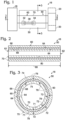
- Fig. 1 is a schematic representation illustrating examples of an actuated assembly 16 including a shape memory alloy (SMA) actuator 50, according to the present disclosure, although not claimed herein.
- actuated assembly 16 includes a base structure 18, an attached component 20, and SMA actuator 50.
- attached component 20 is operatively attached to base structure 18 via and/or utilizing SMA actuator 50 and such that actuation of SMA actuator 50 produces and/or generates relative motion between base structure 18 and attached component 20.
- This is illustrated schematically in Fig. 1 by attached component 20 transitioning from a first, or an initial, orientation relative to base structure 18, as illustrated in solid lines, to a second, or subsequent, orientation relative to base structure 18, as illustrated in dash-dot lines.
- the SMA actuator 50 may produce, generate, regulate, and/or control any suitable motion, or relative motion, between base structure 18 and attached component 20.
- SMA actuator 50 may produce, generate, regulate, control, and/or provide a motive force for one or more of rotary relative motion, linear relative motion, translational relative motion, and/or arcuate relative motion between base structure 18 and attached component 20.
- SMA actuator 50 includes a shape memory alloy torque tube 60 that has an elongate surface and is configured to produce, generate, regulate, control, and/or provide a motive force for rotary relative motion between base structure 18 and attached component 20.
- SMA actuator 50 includes a heat transfer structure 70 that is in mechanical and thermal contact with the elongate surface of SMA torque tube 60.
- a temperature of SMA torque tube 60 may be changed, thereby causing shape memory alloy torque tube 60 to deform and to generate, or to provide the motive force for, relative motion between the base structure and the attached component.
- SMA torque tube 60 may be heated, thereby causing SMA torque tube 60 to deform and/or to transition from a martensite state to an austenite state and causing attached component 20 to transition from the orientation that is illustrated in solid lines in Fig. 1 to the orientation that is illustrated in dash-dot lines.
- SMA torque tube 60 may be cooled, thereby causing SMA torque tube 60 to deform and/or to transition from the austenite state to the martensite state and causing attached component 20 to transition from the orientation that is illustrated in dash-dot lines in Fig. 1 to the orientation that is illustrated in solid lines. This process may be repeated any suitable number of times to produce and/or generate any suitable number of relative orientation transitions between base structure 18 and attached component 20.
- Heat transfer structure 70 may improve, or increase, heat transfer to and/or from the SMA torque tube, thereby increasing a rate at which the SMA torque tube may be transitioned from the martensite state to the austenite state and/or from the austenite state to the martensite state.
- heat transfer structure 70 exerts a retention force 72 on SMA torque tube 60, and retention force 72 retains heat transfer structure 70 in mechanical and thermal contact with SMA torque tube 60.
- Retention force 72 may retain heat transfer structure 70 in mechanical and thermal contact with SMA torque tube 60 despite deformation of SMA torque tube 60 and/or despite relative motion, or even sliding, between a portion of SMA torque tube 60 and a portion of heat transfer structure 70.
- actuated assembly 16 also may include a thermal control assembly 30.
- Thermal control assembly 30, when present, may be configured to control, regulate, and/or specify a temperature of SMA torque tube 60, thereby controlling, regulating, and/or specifying a state of SMA torque tube 60, a deformation of SMA torque tube 60, and/or a relative orientation between base structure 18 and attached component 20.
- Thermal control assembly 30 may include any suitable structure and/or structures.
- thermal control assembly 30 may include a heating assembly 32.
- Heating assembly 32 when present, may be configured to heat SMA torque tube 60, to increase a temperature of SMA torque tube 60, and/or to cause SMA torque tube 60 to transition from the martensite state to the austenite state.
- Examples of heating assembly 32 include any suitable electric heater, resistive heater, and/or inductive heater.
- thermal control assembly 30 additionally or alternatively may include a cooling assembly 34.
- Cooling assembly 34 when present, may be configured to cool SMA torque tube 60, to decrease a temperature of SMA torque tube 60, and/or to transition SMA torque tube 60 from the austenite state to the martensite state.
- Examples of cooling assembly 34 include any suitable convective cooling assembly, conductive cooling assembly, radiative cooling assembly, air conditioning system, solid state cooling assembly, and/or piezoelectric device.
- thermal control assembly 30 additionally or alternatively may include a fluid propulsion system 36.
- Fluid propulsion system 36 may be configured to direct a heat transfer fluid stream in thermal contact with the elongate surface of SMA torque tube 60 and/or with heat transfer structure 70, and it is within the scope of the present disclosure that the heat transfer fluid stream may be utilized to heat and/or to cool SMA torque tube 60.
- heating assembly 32 may be utilized to heat the heat transfer fluid stream and/or cooling assembly 34 may be utilized to cool the heat transfer fluid stream prior to fluid contact between the heat transfer fluid stream and the elongate surface of SMA torque tube 60 and/or prior to fluid contact between the heat transfer fluid stream and heat transfer structure 70.
- Fig. 1 illustrates fluid propulsion system 36 as optionally being included in, forming a portion of, and/or being utilized in conjunction with heating assembly 32 and/or cooling assembly 34.
- heat transfer structure 70 may be adapted, configured, designed, sized, shaped, and/or constructed to increase heat transfer between SMA torque tube 60 and the heat transfer fluid stream when compared to prior art shape memory alloy actuators that do not include, or utilize, heat transfer structure 70.
- thermal control assembly 30 may include heating assembly 32 in the form of an inductive heater, which may be configured to inductively heat SMA torque tube 60.
- thermal control assembly 30 also may include cooling assembly 34 in the form of fluid propulsion system 36, which may be configured to cool SMA torque tube 60 by flowing the heat transfer fluid stream in fluid contact with the elongate surface of SMA torque tube 60 and also in fluid contact with heat transfer structure 70.
- fluid propulsion system 36 examples include any suitable fan, compressor, blower, pump, and/or air inlet that controls and/or regulates flow of the heat transfer fluid stream in thermal contact with the elongate surface of SMA torque tube 60 and/or with heat transfer structure 70.
- the heat transfer fluid stream include a thermally conductive fluid, a refrigerant, a liquid, a gas, and/or air.
- Base structure 18 may include any suitable structure that may be operatively attached to, or may support, SMA actuator 50 and/or attached component 20.
- base structure 18 may include one or more of an aircraft, an airplane, and/or a helicopter.
- attached component 20 may include any suitable structure that may be operatively attached to base structure 18 via SMA actuator 50 and/or that may be moved relative to base structure 18 via actuation of SMA actuator 50.
- attached component 20 may include one or more of an actuated component, a landing gear, a flap, an aileron, and/or a rotor.
- Fig. 2 is a more detailed but still schematic longitudinal cross-sectional view of a shape memory alloy actuator 50, such as shape memory alloy actuator 50 of Fig. 1 , taken along line 2-2 of Fig. 1
- Fig. 3 is a more detailed but still schematic transverse cross-sectional view of SMA actuator 50 taken along line 3-3 of Fig. 1
- SMA actuator 50 includes SMA torque tube 60 that defines a first end 61, a second end 62, and an elongate surface 64 that extends between first end 61 and second end 62.
- Elongate surface 64 is illustrated in dashed lines to indicate that elongate surface 64 can include, or be, an inner surface 66 of SMA torque tube 60 and/or an outer surface 68 of SMA torque tube 60.
- SMA actuator 50 also includes heat transfer structure 70.
- Heat transfer structure 70 is in both mechanical and thermal contact with elongate surface 64 of SMA torque tube 60 and extends at least partially between first end 61 and second end 62 of SMA torque tube 60.
- heat transfer structure 70 exerts retention force 72 on SMA torque tube 60, and retention force 72 retains heat transfer structure 70 in both mechanical and thermal contact with elongate surface 64 of SMA torque tube 60.
- Heat transfer structure 70 also may be referred to herein as being, or may be, in electrical contact, or in direct electrical contact, with elongate surface 64 of SMA torque tube 60.
- Heat transfer structure 70 may exert and/or generate retention force 72 in any suitable manner.
- retention force 72 may include, or be, a restoring force that is generated by heat transfer structure 70.
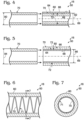
- heat transfer structure 70 may be in mechanical and thermal contact with inner surface 66 of SMA torque tube 60. Stated another way, elongate surface 64 may include, or be, inner surface 66. As such, retention force 72 may extend outward from, generally outward from, or away from, a longitudinal axis 69 of SMA torque tube 60. Under these conditions, heat transfer structure 70 may define an uncompressed, or an average uncompressed, outer dimension 80, which is measured prior to heat transfer structure 70 being combined with SMA torque tube 60 to define SMA actuator 50 (illustrated in solid lines in Fig.
- Uncompressed outer dimension 80 may be greater than compressed outer dimension 82, thereby causing heat transfer structure 70 to exert retention force 72, in the form of the restoring force, on inner surface 66 of SMA torque tube 60.
- heat transfer structure 70 may be in mechanical and thermal contact with outer surface 68 of SMA torque tube 60.
- elongate surface 64 may include, or be, outer surface 68.
- retention force 72 may extend inward toward, generally inward toward, or toward, longitudinal axis 69 of SMA torque tube 60.
- heat transfer structure 70 may define an unexpanded, or an average unexpanded, inner dimension 84, which is measured prior to heat transfer structure 70 being combined with SMA torque tube 60 to define SMA actuator 50 (illustrated in solid lines in Fig.
- Unexpanded inner dimension 84 may be less than expanded inner dimension 86, thereby causing heat transfer structure 70 to exert retention force 72 on outer surface 68 of SMA torque tube 60.
- the heat transfer structure 70 may be retained in mechanical and thermal contact with SMA torque tube 60 solely by retention force 72. Additionally or alternatively, heat transfer structure 70 may be retained in mechanical and thermal contact with SMA torque tube 60 solely by retention force 72. This may include being retained in mechanical and thermal contact with SMA torque tube 60 over at least a threshold fraction of a length 88 (as illustrated in Fig. 2 ) of heat transfer structure 70. Examples of the threshold fraction of length 88 include at least 10%, at least 20%, at least 30%, at least 40%, at least 50%, at least 60% at least 70%, at least 80%, at least 90%, and/or 100% of length 88. Additionally or alternatively, the threshold fraction of length 88 may be at most 90%, at most 80%, at most 70%, at most 60%, or at most 50% of length 88.
- Heat transfer structure 70 may have and/or define any suitable shape and may have, may define, and/or may be shaped to define, a surface area for heat transfer between SMA torque tube 60 and a heat transfer fluid stream that flows in fluid contact therewith.
- heat transfer structure 70 may be helically shaped, at least partially helically shaped, coil-shaped, at least partially coil-shaped, spiral-shaped, at least partially spiral-shaped, arcuate, and/or at least partially arcuate.
- heat transfer structure 70 may include at least one, or even a plurality of, surface-contacting regions 74 that mechanically and thermally contact elongate surface 64 of SMA torque tube 60 and apply retention force 72 to SMA torque tube 60.
- heat transfer structure 70 also may include a plurality of projecting regions 76 that project from, or away from, elongate surface 64. This may include projecting away from elongate surface 64 at any suitable angle. As an example, projecting regions 76 may project perpendicular, or at least substantially perpendicular, to elongate surface 64.
- each surface-contacting region 74 may be spaced apart from an adjacent surface-contacting region 74 by a corresponding projecting region 76, as illustrated in Figs. 8-9 . Additionally or alternatively, the plurality of surface-contacting regions 74 may form a continuous, or at least substantially continuous, surface-contacting region 74, as illustrated in Figs. 10-11 .
- heat transfer structure 70 may include, be, and/or be at least partially defined by an elongate conductive body 71. It is within the scope of the present disclosure that elongate conductive body 71 may define, or may be shaped to define, both surface-contacting regions 74 and projecting regions 76, as illustrated in Figs. 8-9 . Under these conditions, elongate conductive body 71 may have, or define, a body length, and elongate conductive body 71 may be in mechanical and thermal contact with elongate surface 64 of SMA torque tube 60 over a fraction of the body length.
- the fraction of the body length may be at least 10%, at least 20%, at least 30%, at least 40%, and/or at least 50% of the body length. Additionally or alternatively, the fraction of the body length may be at most 100%, at most 90%, at most 80%, at most 70%, at most 60%, or at most 50% of the body length.
- At least a subset, or fraction, of the plurality of projecting regions 76 when present, may be operatively attached to elongate conductive body 71, as illustrated in Figs. 10-11 .
- projecting regions 76 may be adhered, brazed, and/or welded to elongate conductive body 71.
- Elongate conductive body 71 forms and/or defines an entirety of heat transfer structure 70.
- Elongate conductive body 71 includes a plurality of helical, or at least substantially helical, regions, which are in mechanical and thermal contact with elongate surface 64 of SMA torque tube 60 and define surface-contacting regions 74.
- elongate conductive body 71 also includes a plurality of deviation regions, which deviate from a helical shape and project away from elongate surface 64 to define projecting regions 76. As illustrated, a corresponding deviation (i.e., projecting region 76) extends between each adjacent pair of helical regions (i.e., surface-contacting regions 74).
- the heat transfer structure 70 may have and/or define any suitable cross-sectional shape, or transverse cross-sectional shape.
- heat transfer structure 70 may include one or more subtraction regions 78, which also may be referred to herein as void spaces 78, machined regions 78, and/or subtractively machined regions 78.
- subtraction regions 78 may increase a surface area of heat transfer structure 70, thereby improving convective heat transfer between heat transfer structure 70 and the heat transfer fluid stream.
- heat transfer structure 70 may be shaped such that a surface of heat transfer structure 70 that is in mechanical and thermal contact with elongate surface 64 of SMA torque tube 60 may be in face-to-face, or at least partial face-to-face, contact with elongate surface 64.
- Fig. 13 is a less schematic transverse cross-sectional view of an example of an elongate conductive body 71 that defines a heat transfer structure 70 according to the present disclosure.
- heat transfer structure 70 may define a conductive heat transfer surface 92 and a convective heat transfer surface 94.
- Conductive heat transfer surface 92 may be shaped to mechanically and thermally contact elongate surface 64 of SMA torque tube 60, while convective heat transfer surface 94 may be shaped for heat transfer with the heat transfer fluid stream.
- a transverse cross-section of conductive heat transfer surface 92 may be linear, or at least substantially linear.
- a transverse cross-section of convective heat transfer surface 94 may be nonlinear, arcuate, partially circular, partially elliptical, and/or D-shaped.
- a radius of curvature of conductive heat transfer surface 92 may be greater than a radius of curvature of convective heat transfer surface 94, and both radii of curvature may be measured in the transverse cross-section of elongate conductive body 71.
- Heat transfer structure 70 may be formed from and/or defined by any suitable heat transfer material, and the heat transfer material may be different from a shape memory alloy that defines SMA torque tube 60.
- the heat transfer material may have a greater thermal conductivity than the shape memory alloy.
- the heat transfer material may have a greater stiffness than the shape memory alloy.
- the heat transfer material may have a greater electronegativity than the shape memory alloy such that the heat transfer material functions as a sacrificial anode for the shape memory alloy.
- Examples of the heat transfer material include a resilient material, aluminum, an aluminum alloy, copper, a copper alloy, brass, and red brass.
- Examples of the shape memory alloy include a binary alloy, a nickel-titanium alloy, a binary nickel-titanium alloy, a ternary alloy, a ternary alloy that includes nickel and titanium and further includes hafnium, copper, iron, silver, cobalt, chromium, vanadium, and/or a quaternary alloy.
- SMA torque tube 60 may be tubular and/or cylindrical.
- SMA torque tube 60 may be a hollow SMA torque tube and heat transfer structure 70 may extend therein.
- SMA torque tube 60 may define both inner surface 66 and outer surface 68, which are discussed herein.
- shape memory alloy actuators 50 may include a thermal sensor 90.
- Thermal sensor 90 when present, may be configured to detect a temperature of SMA torque tube 60.
- thermal sensor 90 may be operatively attached to heat transfer structure 90 and/or may be pressed into mechanical and thermal contact with SMA torque tube 60 via and/or utilizing heat transfer structure 70. Under these conditions, thermal sensor 90 may not be, or may not be required to be, adhered and/or affixed to a specific region of SMA torque tube 60.
- thermal sensor 90 include a thermocouple, a thermistor, and/or a resistance temperature detector (RTD).
- Fig. 14 is a flowchart depicting methods 100, according to the present disclosure, of manufacturing a shape memory alloy actuator, such as shape memory alloy actuator 50 of Figs. 1-13 .
- Methods 100 include providing a shape memory alloy (SMA) torque tube at 110, providing a heat transfer structure at 120, applying a dimension-modifying force at 130, combining the SMA torque tube and the heat transfer structure at 140, and releasing the dimension-modifying force at 150.
- SMA shape memory alloy
- Providing the shape memory alloy (SMA) torque tube at 110 may include providing any suitable SMA torque tube, examples of which are discussed herein with reference to SMA torque tube 60.
- the SMA torque tube may have and/or define a first end, a second end, and an elongate surface that extends between the first end and the second end.
- the providing at 110 may include providing in any suitable manner. As examples, the providing at 110 may include purchasing, obtaining, ordering, and/or fabricating the SMA torque tube.
- Providing the heat transfer structure at 120 may include providing any suitable heat transfer structure, examples of which are discussed herein with reference to heat transfer structure 70.
- the providing at 120 may include providing in any suitable manner.
- the providing at 120 may include purchasing, obtaining, ordering, and/or fabricating the heat transfer structure.
- Applying the dimension-modifying force at 130 may include applying any suitable dimension-modifying force to the heat transfer structure, and application of the dimension-modifying force may permit and/or facilitate the combining at 140.
- the applying at 130 may include applying the dimension-modifying force to place the heat-transfer structure in a modified-dimensional conformation such that a modified characteristic dimension of the heat transfer structure differs from a natural, or unmodified, characteristic dimension of the heat transfer structure that may be exhibited by the heat transfer structure prior to application of the dimension-modifying force to the heat transfer structure.
- the applying at 130 may include twisting the heat transfer structure, as indicated at 132, compressing the heat transfer structure, as indicated at 134, and/or expanding the heat transfer structure, as indicated at 136.
- Combining the SMA torque tube and the heat transfer structure at 140 may include combining such that the heat transfer structure extends at least partially between the first end of the SMA torque tube and the second end of the SMA torque tube and/or combining such that the heat transfer structure extends along, in contact with, and/or parallel to the elongate surface of the SMA torque tube.
- the elongate surface of the SMA torque tube may include, or be, an inner surface of the SMA torque tube.
- the applying at 130 may include the twisting at 132 and/or the compressing at 134, such that the modified characteristic dimension is less than the natural characteristic dimension, and the combining at 140 may include inserting the heat transfer structure within the SMA torque tube, as indicated at 142.
- the elongate surface of the SMA torque tube may include, or be, an outer surface of the SMA torque tube.
- the applying at 130 may include the twisting at 132 and/or the expanding at 136, such that the modified characteristic dimension is greater than the natural characteristic dimension, and the combining at 140 may include extending the heat transfer structure around, or about, the SMA torque tube, as indicated at 144.
- Releasing the dimension-modifying force at 150 may include releasing the dimension-modifying force such that the heat transfer structure transitions to an intermediate conformation in which an intermediate characteristic dimension of the heat transfer is between the modified characteristic dimension and the natural characteristic dimension.
- the heat transfer structure may exert a restoring force, which may tend to return the heat transfer structure to the natural characteristic dimension, and this restoring force may cause the heat transfer structure to exert a retention force on the elongate surface of the SMA torque tube. This retention force may retain the heat transfer structure in mechanical and thermal contact with the elongate surface of the SMA torque tube.
- the terms “adapted” and “configured” mean that the element, component, or other subject matter is designed and/or intended to perform a given function. Thus, the use of the terms “adapted” and “configured” should not be construed to mean that a given element, component, or other subject matter is simply “capable of” performing a given function but that the element, component, and/or other subject matter is specifically selected, created, implemented, utilized, programmed, and/or designed for the purpose of performing the function. It is also within the scope of the present disclosure that elements, components, and/or other recited subject matter that is recited as being adapted to perform a particular function may additionally or alternatively be described as being configured to perform that function, and vice versa. Similarly, subject matter that is recited as being configured to perform a particular function may additionally or alternatively be described as being operative to perform that function.
- the phrase "at least one,” in reference to a list of one or more entities should be understood to mean at least one entity selected from any one or more of the entity in the list of entities, but not necessarily including at least one of each and every entity specifically listed within the list of entities and not excluding any combinations of entities in the list of entities.
- This definition also allows that entities may optionally be present other than the entities specifically identified within the list of entities to which the phrase "at least one" refers, whether related or unrelated to those entities specifically identified.
- At least one of A and B may refer, in one embodiment, to at least one, optionally including more than one, A, with no B present (and optionally including entities other than B); in another embodiment, to at least one, optionally including more than one, B, with no A present (and optionally including entities other than A); in yet another embodiment, to at least one, optionally including more than one, A, and at least one, optionally including more than one, B (and optionally including other entities).
- each of the expressions “at least one of A, B and C,” “at least one of A, B, or C,” “one or more of A, B, and C,” “one or more of A, B, or C” and “A, B, and/or C” may mean A alone, B alone, C alone, A and B together, A and C together, B and C together, A, B and C together, and optionally any of the above in combination with at least one other entity.
Landscapes
- Engineering & Computer Science (AREA)
- Chemical & Material Sciences (AREA)
- Combustion & Propulsion (AREA)
- Mechanical Engineering (AREA)
- General Engineering & Computer Science (AREA)
- Media Introduction/Drainage Providing Device (AREA)
- Endoscopes (AREA)
Description
- The present disclosure relates generally to shape memory alloy actuators, and more particularly to shape memory alloy actuators with heat transfer structures, and/or to methods of manufacturing the shape memory alloy actuators.
- Shape memory alloy actuators are solid state actuators that may be utilized to provide a motive force for motion of one object, such as an attached component, relative to another object, such as a base structure to which the attached component is attached via the shape memory alloy actuator. Shape memory alloy actuators may generate the motive force via a phase change within a shape memory alloy element thereof, and this phase change may be initiated by a temperature change. As an example, the shape memory alloy element may transition from a martensite state to an austenite state upon being heated and also may transition from the austenite state to the martensite state upon being cooled.
- Heating of the shape memory alloy element historically has been accomplished utilizing a heating assembly, such as a resistive heating element and/or an inductive heating element. In contrast, cooling of the shape memory alloy element historically has been accomplished via convective cooling with a heat transfer fluid stream. The heating generally may be performed relatively quickly; however, the cooling often takes a significantly longer amount of time and thus may be rate-limiting to an overall cycle time of the shape memory alloy actuator (e.g., a time needed to transition the shape memory alloy element from the martensite state to the austenite state and back to the martensite state or vice versa).
- In general, a rate of convective cooling may be increased by increasing a surface area for heat transfer between a body to be cooled and a heat transfer fluid stream that flows in fluid contact with the body to be cooled. As an example, cooling fins may be affixed to the body to be cooled and/or may be defined by the body to be cooled.
- While such an approach may be effective under certain circumstances, it may be difficult, or even impossible, to effectively and reliably implement in the context of a shape memory alloy element. As an example, the shape memory alloy element may experience significant physical deformation upon transitioning between the martensite state and the austenite state, and this physical deformation may make it difficult, or even impossible, to operatively attach cooling fins to the shape memory alloy element. As another example, a shape memory alloy that defines the shape memory alloy element may have a low thermal conductivity, and cooling fins that might be defined by the shape memory alloy element itself may not be effective at improving convective cooling of the shape memory alloy element. Thus, there exists a need for improved shape memory alloy actuators with heat transfer structures, for actuated assemblies that include the improved shape memory alloy actuators, and/or for methods of manufacturing the improved shape memory alloy actuators.
-
CA 2910896 , in accordance with its abstract, states an SMA actuator that includes a cooling device disposed within a torque tube. In one aspect, the cooling device includes a sliding sleeve, an expandable sleeve, and plurality of cooling fins coupled to the expandable sleeve. Axial movement of the sliding sleeve relative to the expandable sleeve facilitates radial expansion of the expandable sleeve and urges the cooling fins into contact with the torque tube. The cooling fins function as heat sinks when in contact with the torque tube to facilitate the removal of heat from the torque tube to increase the cooling rate of the torque tube. During heating of the torque tube, the cooling fins may be spaced apart from the torque tube to reduce the thermal mass that is heated, thus increasing the heating rate of the torque tube. -
US 20150096293 , in accordance with its abstract, states a system for heating a shape memory alloy (SMA) actuator which include an SMA actuator, a smart susceptor, a plurality of induction coils, and a control module. The SMA actuator may have at least one layup. The SMA actuator may be selectively heated to a transition temperature. The smart susceptor may be in thermal contact with the at least one layup of the SMA actuator. The induction heating coils may be configured to receive an alternating current and generate a magnetic field based on the alternating current. The magnetic field may create an eddy current in at least one of the SMA actuator and the smart susceptor to heat the SMA actuator to the transition temperature. The control module may be configured to drive the alternating current supplied to the induction heating coils. -
US 5975468 , in accordance with its abstract, states a rotary actuator includes a bar made of shape memory alloy having ends provided with thermally insulating interface elements for interfacing with elements that are to be rotated relative to each other. An electric heater surrounds the bar and is apt to heat it above its transition temperature to the austenitic domain. The actuator is suitable for deploying or rotating solar panels. -
US 6065934 , in accordance with its abstract, states a rotary actuator including an actuator assembly. The actuator assembly includes a torque tube formed of a shape memory alloy, a super elastic NiTinol return spring having a proximal end and a distal end, and a torque tube heating element positioned near the torque tube. The torque tube includes a proximal end and a distal end. The return spring and torque tube are connected at their ends, with the torque tube being pretwisted while in a martensitic state relative to the spring. Activation of the heating element causes the torque tube to enter an austenitic state in which it returns to its previous untwisted configuration. Removal of heat allows the torque tube to return to a martensitic state, further allowing the return spring to retwist the torque tube. Further provided is a unique locking assembly for use with the actuator assembly. Further provided is a helicopter blade twist rotation system for use with a rotor craft blade having a blade root and a tip. The system includes a shape memory alloy rotary actuator located within the blade near the blade root, and a passive torque tube located within the blade and having a proximal end connected to the rotary actuator and a distal end connected to the blade near to the blade tip. -
US 20130046285 , in accordance with its abstract, states an elongate medical device including an inner elongate member, a reinforcing member, and an outer tubular member is described. The reinforcing member may be a helically wound continuous wire including a first portion having a first cross-sectional profile, a second portion having a second cross-sectional profile, and a transition region located between the first portion and the second portion. The first cross-sectional profile may be different from the second cross-sectional profile. In some embodiments, the first cross-sectional profile may be circular or non-circular and the second cross-sectional profile may be circular or non-circular. - Shape memory alloy actuators with heat transfer structures, and methods of manufacturing the same are disclosed herein, as defined in the appended claims.
- A shape memory alloy (SMA) actuator according to the present disclosure is defined in appended claim 1, and includes a shape memory alloy torque tube and a heat transfer structure. The shape memory alloy torque tube has a first end, a second end, and an elongate surface extending between the first end and the second end. The heat transfer structure is in mechanical and thermal contact with the elongate surface of the SMA torque tube and extends at least partially between the first end and the second end of the SMA torque tube. The heat transfer structure also exerts a retention force on the SMA torque tube that retains the heat transfer structure in mechanical and thermal contact with the elongate surface of the SMA torque tube.
- A method according to the present disclosure of manufacturing said shape memory alloy actuator is defined in appended claim 13, and includes providing a shape memory alloy torque tube, providing a heat transfer structure, applying a dimension-modifying force to the heat transfer structure, combining the heat transfer structure with the shape memory alloy torque tube, and releasing the dimension-modifying force. The applying the dimension-modifying force may include applying to place the heat transfer structure in a modified-dimensional conformation such that a modified characteristic dimension of the heat transfer structure differs from a natural characteristic dimension of the heat transfer structure prior to application of the dimension-modifying force. The combining includes combining such that the heat transfer structure extends at least partially between a first end and a second end of the SMA torque tube. The releasing includes releasing such that the heat transfer structure exerts a retention force on an elongate surface of the SMA torque tube.
-
-
Fig. 1 is a schematic representation illustrating examples of an actuated assembly including a shape memory alloy actuator, according to the present disclosure but not claimed herein. -
Fig. 2 is a more detailed but still schematic longitudinal cross-sectional view of the shape memory alloy actuator ofFig. 1 taken along line 2-2 ofFig. 1 . -
Fig. 3 is a more detailed but still schematic transverse cross-sectional view of the shape memory alloy actuator ofFigs. 1-2 taken along line 3-3 ofFig. 1 . -
Fig. 4 is a partial schematic transverse cross-sectional view illustrating assembly of shape memory alloy actuators according to the present disclosure but not claimed herein. -
Fig. 5 is a partial schematic transverse cross-sectional view illustrating assembly of shape memory alloy actuators according to the present disclosure but not claimed herein. -
Fig. 6 is a less schematic partial transverse cross-sectional view illustrating an example of a shape memory alloy actuator according to the present disclosure but not claimed herein. -
Fig. 7 is a transverse cross-sectional view of the shape memory alloy actuator ofFig. 6 taken along line 7-7 ofFig. 6 . -
Fig. 8 is a less schematic partial transverse cross-sectional view illustrating an example of a shape memory alloy actuator according to the present disclosure as claimed herein. -
Fig. 9 is a transverse cross-sectional view of the shape memory alloy actuator ofFig. 8 taken along line 9-9 ofFig. 8 . -
Fig. 10 is a less schematic partial transverse cross-sectional view illustrating an example of a shape memory alloy actuator according to the present disclosure but not claimed herein. -
Fig. 11 is a transverse cross-sectional view of the shape memory alloy actuator ofFig. 10 taken along 11-11 ofFig. 10 . -
Fig. 12 is a less schematic transverse cross-sectional view illustrating an example of a shape memory alloy actuator according to the present disclosure but not claimed herein. -
Fig. 13 is a less schematic transverse cross-sectional view of an example of an elongate conductive body that defines a heat transfer structure according to the present disclosure but not claimed herein. -
Fig. 14 is a flowchart depicting methods, according to the present disclosure, of manufacturing a shape memory alloy actuator. -
Figs. 1-14 provide illustrative, non-exclusive examples of shapememory alloy actuators 50, according to the present disclosure, some being claimed herein and others not, of actuatedassemblies 16 including shapememory alloy actuators 50, and/or ofmethods 100, of manufacturing shape memory alloy actuators, such as shapememory alloy actuators 50. Elements that serve a similar, or at least substantially similar, purpose are labeled with like numbers in each ofFigs. 1-14 , and these elements may not be discussed in detail herein with reference to each ofFigs. 1-14 . Similarly, all elements may not be labeled in each ofFigs. 1-14 , but reference numerals associated therewith may be utilized herein for consistency. Elements, components, and/or features that are discussed herein with reference to one or more ofFigs. 1-14 may be included in and/or utilized with any ofFigs. 1-14 . - In general, elements that are likely to be included in a given (i.e., a particular) example are illustrated in solid lines, while elements that are optional to a given example are illustrated in dashed lines. However, elements that are shown in solid lines are not essential to all examples, and an element shown in solid lines may be omitted from a particular example.
-
Fig. 1 is a schematic representation illustrating examples of an actuatedassembly 16 including a shape memory alloy (SMA)actuator 50, according to the present disclosure, although not claimed herein. As illustrated in solid lines inFig. 1 , actuatedassembly 16 includes abase structure 18, an attachedcomponent 20, andSMA actuator 50. As also illustrated inFig. 1 , attachedcomponent 20 is operatively attached tobase structure 18 via and/or utilizingSMA actuator 50 and such that actuation ofSMA actuator 50 produces and/or generates relative motion betweenbase structure 18 and attachedcomponent 20. This is illustrated schematically inFig. 1 by attachedcomponent 20 transitioning from a first, or an initial, orientation relative tobase structure 18, as illustrated in solid lines, to a second, or subsequent, orientation relative tobase structure 18, as illustrated in dash-dot lines. - The
SMA actuator 50 may produce, generate, regulate, and/or control any suitable motion, or relative motion, betweenbase structure 18 and attachedcomponent 20. As examples,SMA actuator 50 may produce, generate, regulate, control, and/or provide a motive force for one or more of rotary relative motion, linear relative motion, translational relative motion, and/or arcuate relative motion betweenbase structure 18 and attachedcomponent 20. As a more specific example, and as discussed in more detail herein with reference toFigs. 2-13 ,SMA actuator 50 includes a shape memoryalloy torque tube 60 that has an elongate surface and is configured to produce, generate, regulate, control, and/or provide a motive force for rotary relative motion betweenbase structure 18 and attachedcomponent 20. As also discussed in more detail herein with reference toFigs. 2-13 ,SMA actuator 50 includes aheat transfer structure 70 that is in mechanical and thermal contact with the elongate surface ofSMA torque tube 60. - During operation of actuated
assemblies 16 includingSMA actuators 50, according to the present disclosure, a temperature ofSMA torque tube 60 may be changed, thereby causing shape memoryalloy torque tube 60 to deform and to generate, or to provide the motive force for, relative motion between the base structure and the attached component. As an example,SMA torque tube 60 may be heated, thereby causingSMA torque tube 60 to deform and/or to transition from a martensite state to an austenite state and causing attachedcomponent 20 to transition from the orientation that is illustrated in solid lines inFig. 1 to the orientation that is illustrated in dash-dot lines. As another example,SMA torque tube 60 may be cooled, thereby causingSMA torque tube 60 to deform and/or to transition from the austenite state to the martensite state and causing attachedcomponent 20 to transition from the orientation that is illustrated in dash-dot lines inFig. 1 to the orientation that is illustrated in solid lines. This process may be repeated any suitable number of times to produce and/or generate any suitable number of relative orientation transitions betweenbase structure 18 and attachedcomponent 20. -
Heat transfer structure 70 may improve, or increase, heat transfer to and/or from the SMA torque tube, thereby increasing a rate at which the SMA torque tube may be transitioned from the martensite state to the austenite state and/or from the austenite state to the martensite state. In addition, and as discussed in more detail herein with reference toFigs. 3-5 and8-11 ,heat transfer structure 70 exerts aretention force 72 onSMA torque tube 60, andretention force 72 retainsheat transfer structure 70 in mechanical and thermal contact withSMA torque tube 60.Retention force 72 may retainheat transfer structure 70 in mechanical and thermal contact withSMA torque tube 60 despite deformation ofSMA torque tube 60 and/or despite relative motion, or even sliding, between a portion ofSMA torque tube 60 and a portion ofheat transfer structure 70. - As illustrated in dashed lines in
Fig. 1 , actuatedassembly 16 also may include athermal control assembly 30.Thermal control assembly 30, when present, may be configured to control, regulate, and/or specify a temperature ofSMA torque tube 60, thereby controlling, regulating, and/or specifying a state ofSMA torque tube 60, a deformation ofSMA torque tube 60, and/or a relative orientation betweenbase structure 18 and attachedcomponent 20. -
Thermal control assembly 30 may include any suitable structure and/or structures. As an example,thermal control assembly 30 may include aheating assembly 32.Heating assembly 32, when present, may be configured to heatSMA torque tube 60, to increase a temperature ofSMA torque tube 60, and/or to causeSMA torque tube 60 to transition from the martensite state to the austenite state. Examples ofheating assembly 32 include any suitable electric heater, resistive heater, and/or inductive heater. - As another example,
thermal control assembly 30 additionally or alternatively may include a cooling assembly 34. Cooling assembly 34, when present, may be configured to coolSMA torque tube 60, to decrease a temperature ofSMA torque tube 60, and/or to transitionSMA torque tube 60 from the austenite state to the martensite state. Examples of cooling assembly 34 include any suitable convective cooling assembly, conductive cooling assembly, radiative cooling assembly, air conditioning system, solid state cooling assembly, and/or piezoelectric device. - As yet another example,
thermal control assembly 30 additionally or alternatively may include afluid propulsion system 36.Fluid propulsion system 36 may be configured to direct a heat transfer fluid stream in thermal contact with the elongate surface ofSMA torque tube 60 and/or withheat transfer structure 70, and it is within the scope of the present disclosure that the heat transfer fluid stream may be utilized to heat and/or to coolSMA torque tube 60. Under these conditions,heating assembly 32 may be utilized to heat the heat transfer fluid stream and/or cooling assembly 34 may be utilized to cool the heat transfer fluid stream prior to fluid contact between the heat transfer fluid stream and the elongate surface ofSMA torque tube 60 and/or prior to fluid contact between the heat transfer fluid stream andheat transfer structure 70. - With this in mind,
Fig. 1 illustratesfluid propulsion system 36 as optionally being included in, forming a portion of, and/or being utilized in conjunction withheating assembly 32 and/or cooling assembly 34. In addition, and as discussed in more detail herein,heat transfer structure 70 may be adapted, configured, designed, sized, shaped, and/or constructed to increase heat transfer betweenSMA torque tube 60 and the heat transfer fluid stream when compared to prior art shape memory alloy actuators that do not include, or utilize,heat transfer structure 70. - As a more specific but still illustrative, non-exclusive example,
thermal control assembly 30 may includeheating assembly 32 in the form of an inductive heater, which may be configured to inductively heatSMA torque tube 60. In addition,thermal control assembly 30 also may include cooling assembly 34 in the form offluid propulsion system 36, which may be configured to coolSMA torque tube 60 by flowing the heat transfer fluid stream in fluid contact with the elongate surface ofSMA torque tube 60 and also in fluid contact withheat transfer structure 70. - Examples of
fluid propulsion system 36 include any suitable fan, compressor, blower, pump, and/or air inlet that controls and/or regulates flow of the heat transfer fluid stream in thermal contact with the elongate surface ofSMA torque tube 60 and/or withheat transfer structure 70. Examples of the heat transfer fluid stream include a thermally conductive fluid, a refrigerant, a liquid, a gas, and/or air. -
Base structure 18 may include any suitable structure that may be operatively attached to, or may support,SMA actuator 50 and/or attachedcomponent 20. As examples,base structure 18 may include one or more of an aircraft, an airplane, and/or a helicopter. Similarly, attachedcomponent 20 may include any suitable structure that may be operatively attached tobase structure 18 viaSMA actuator 50 and/or that may be moved relative tobase structure 18 via actuation ofSMA actuator 50. As examples, attachedcomponent 20 may include one or more of an actuated component, a landing gear, a flap, an aileron, and/or a rotor. -
Fig. 2 is a more detailed but still schematic longitudinal cross-sectional view of a shapememory alloy actuator 50, such as shapememory alloy actuator 50 ofFig. 1 , taken along line 2-2 ofFig. 1 , whileFig. 3 is a more detailed but still schematic transverse cross-sectional view ofSMA actuator 50 taken along line 3-3 ofFig. 1 . As illustrated collectively byFigs. 2-3 in an example not claimed herein,SMA actuator 50 includesSMA torque tube 60 that defines afirst end 61, asecond end 62, and anelongate surface 64 that extends betweenfirst end 61 andsecond end 62.Elongate surface 64 is illustrated in dashed lines to indicate thatelongate surface 64 can include, or be, aninner surface 66 ofSMA torque tube 60 and/or anouter surface 68 ofSMA torque tube 60. -
SMA actuator 50 also includesheat transfer structure 70.Heat transfer structure 70 is in both mechanical and thermal contact withelongate surface 64 ofSMA torque tube 60 and extends at least partially betweenfirst end 61 andsecond end 62 ofSMA torque tube 60. In addition, and as illustrated inFigs. 3-5 and8-11 ,heat transfer structure 70 exertsretention force 72 onSMA torque tube 60, andretention force 72 retainsheat transfer structure 70 in both mechanical and thermal contact withelongate surface 64 ofSMA torque tube 60.Heat transfer structure 70 also may be referred to herein as being, or may be, in electrical contact, or in direct electrical contact, withelongate surface 64 ofSMA torque tube 60. -
Heat transfer structure 70 may exert and/or generateretention force 72 in any suitable manner. As an example,retention force 72 may include, or be, a restoring force that is generated byheat transfer structure 70. - As a more specific example not claimed herein and as illustrated in dash-dot lines in
Fig. 4 ,heat transfer structure 70 may be in mechanical and thermal contact withinner surface 66 ofSMA torque tube 60. Stated another way,elongate surface 64 may include, or be,inner surface 66. As such,retention force 72 may extend outward from, generally outward from, or away from, alongitudinal axis 69 ofSMA torque tube 60. Under these conditions,heat transfer structure 70 may define an uncompressed, or an average uncompressed,outer dimension 80, which is measured prior toheat transfer structure 70 being combined withSMA torque tube 60 to define SMA actuator 50 (illustrated in solid lines inFig. 4 ), and a compressed, or an average compressed,outer dimension 82, which is measured subsequent to heattransfer structure 70 being combined withSMA torque tube 60 to define SMA actuator 50 (illustrated in dash-dot lines inFig. 4 ). Uncompressedouter dimension 80 may be greater than compressedouter dimension 82, thereby causingheat transfer structure 70 to exertretention force 72, in the form of the restoring force, oninner surface 66 ofSMA torque tube 60. - As another more specific example not claimed herein and as illustrated in dash-dot lines in
Fig. 5 ,heat transfer structure 70 may be in mechanical and thermal contact withouter surface 68 ofSMA torque tube 60. Stated another way,elongate surface 64 may include, or be,outer surface 68. As such,retention force 72 may extend inward toward, generally inward toward, or toward,longitudinal axis 69 ofSMA torque tube 60. Under these conditions,heat transfer structure 70 may define an unexpanded, or an average unexpanded,inner dimension 84, which is measured prior toheat transfer structure 70 being combined withSMA torque tube 60 to define SMA actuator 50 (illustrated in solid lines inFig. 5 ), and an expanded, or an average expanded,inner dimension 86, which is measured subsequent to heattransfer structure 70 being combined withSMA torque tube 60 to define SMA actuator 50 (illustrated in dash-dot lines inFig. 5 ). Unexpandedinner dimension 84 may be less than expandedinner dimension 86, thereby causingheat transfer structure 70 to exertretention force 72 onouter surface 68 ofSMA torque tube 60. - The
heat transfer structure 70 may be retained in mechanical and thermal contact withSMA torque tube 60 solely byretention force 72. Additionally or alternatively,heat transfer structure 70 may be retained in mechanical and thermal contact withSMA torque tube 60 solely byretention force 72. This may include being retained in mechanical and thermal contact withSMA torque tube 60 over at least a threshold fraction of a length 88 (as illustrated inFig. 2 ) ofheat transfer structure 70. Examples of the threshold fraction oflength 88 include at least 10%, at least 20%, at least 30%, at least 40%, at least 50%, at least 60% at least 70%, at least 80%, at least 90%, and/or 100% oflength 88. Additionally or alternatively, the threshold fraction oflength 88 may be at most 90%, at most 80%, at most 70%, at most 60%, or at most 50% oflength 88. -
Heat transfer structure 70 may have and/or define any suitable shape and may have, may define, and/or may be shaped to define, a surface area for heat transfer betweenSMA torque tube 60 and a heat transfer fluid stream that flows in fluid contact therewith. As an example, and as illustrated inFigs. 6-11 ,heat transfer structure 70 may be helically shaped, at least partially helically shaped, coil-shaped, at least partially coil-shaped, spiral-shaped, at least partially spiral-shaped, arcuate, and/or at least partially arcuate. As another example not claimed herein and as illustrated schematically inFig. 3 and less schematically inFigs. 10-11 ,heat transfer structure 70 may include at least one, or even a plurality of, surface-contactingregions 74 that mechanically and thermally contactelongate surface 64 ofSMA torque tube 60 and applyretention force 72 toSMA torque tube 60. In addition,heat transfer structure 70 also may include a plurality of projectingregions 76 that project from, or away from,elongate surface 64. This may include projecting away fromelongate surface 64 at any suitable angle. As an example, projectingregions 76 may project perpendicular, or at least substantially perpendicular, to elongatesurface 64. - When
heat transfer structure 70 includes the plurality of surface-contactingregions 74 and the plurality of projectingregions 76, each surface-contactingregion 74 may be spaced apart from an adjacent surface-contactingregion 74 by a corresponding projectingregion 76, as illustrated inFigs. 8-9 . Additionally or alternatively, the plurality of surface-contactingregions 74 may form a continuous, or at least substantially continuous, surface-contactingregion 74, as illustrated inFigs. 10-11 . - As illustrated schematically in
Fig. 3 and less schematically inFigs. 6-7 ,10-11 ,heat transfer structure 70 may include, be, and/or be at least partially defined by an elongateconductive body 71. It is within the scope of the present disclosure that elongateconductive body 71 may define, or may be shaped to define, both surface-contactingregions 74 and projectingregions 76, as illustrated inFigs. 8-9 . Under these conditions, elongateconductive body 71 may have, or define, a body length, and elongateconductive body 71 may be in mechanical and thermal contact withelongate surface 64 ofSMA torque tube 60 over a fraction of the body length. As examples, the fraction of the body length may be at least 10%, at least 20%, at least 30%, at least 40%, and/or at least 50% of the body length. Additionally or alternatively, the fraction of the body length may be at most 100%, at most 90%, at most 80%, at most 70%, at most 60%, or at most 50% of the body length. - Additionally or alternatively, at least a subset, or fraction, of the plurality of projecting
regions 76, when present, may be operatively attached to elongateconductive body 71, as illustrated inFigs. 10-11 . As an example, projectingregions 76 may be adhered, brazed, and/or welded to elongateconductive body 71. - Turning now more specifically to
Figs. 8-9 , an embodiment of a shapememory alloy actuator 50, as claimed herein, is illustrated in which an elongateconductive body 71 forms and/or defines an entirety ofheat transfer structure 70. Elongateconductive body 71 includes a plurality of helical, or at least substantially helical, regions, which are in mechanical and thermal contact withelongate surface 64 ofSMA torque tube 60 and define surface-contactingregions 74. In addition, elongateconductive body 71 also includes a plurality of deviation regions, which deviate from a helical shape and project away fromelongate surface 64 to define projectingregions 76. As illustrated, a corresponding deviation (i.e., projecting region 76) extends between each adjacent pair of helical regions (i.e., surface-contacting regions 74). - The
heat transfer structure 70 may have and/or define any suitable cross-sectional shape, or transverse cross-sectional shape. As an example, and as illustrated inFigs. 3 and12 ,heat transfer structure 70 may include one ormore subtraction regions 78, which also may be referred to herein asvoid spaces 78, machinedregions 78, and/or subtractivelymachined regions 78.Such subtraction regions 78 may increase a surface area ofheat transfer structure 70, thereby improving convective heat transfer betweenheat transfer structure 70 and the heat transfer fluid stream. - As another example,
heat transfer structure 70 may be shaped such that a surface ofheat transfer structure 70 that is in mechanical and thermal contact withelongate surface 64 ofSMA torque tube 60 may be in face-to-face, or at least partial face-to-face, contact withelongate surface 64. This is illustrated inFig. 13 , which is a less schematic transverse cross-sectional view of an example of an elongateconductive body 71 that defines aheat transfer structure 70 according to the present disclosure. As illustrated therein,heat transfer structure 70 may define a conductiveheat transfer surface 92 and a convectiveheat transfer surface 94. Conductiveheat transfer surface 92 may be shaped to mechanically and thermally contactelongate surface 64 ofSMA torque tube 60, while convectiveheat transfer surface 94 may be shaped for heat transfer with the heat transfer fluid stream. As an example, and as illustrated, a transverse cross-section of conductiveheat transfer surface 92 may be linear, or at least substantially linear. In contrast, and as also illustrated, a transverse cross-section of convectiveheat transfer surface 94 may be nonlinear, arcuate, partially circular, partially elliptical, and/or D-shaped. Additionally or alternatively, a radius of curvature of conductiveheat transfer surface 92 may be greater than a radius of curvature of convectiveheat transfer surface 94, and both radii of curvature may be measured in the transverse cross-section of elongateconductive body 71. -
Heat transfer structure 70 may be formed from and/or defined by any suitable heat transfer material, and the heat transfer material may be different from a shape memory alloy that definesSMA torque tube 60. As an example, the heat transfer material may have a greater thermal conductivity than the shape memory alloy. As another example, the heat transfer material may have a greater stiffness than the shape memory alloy. As yet another example, the heat transfer material may have a greater electronegativity than the shape memory alloy such that the heat transfer material functions as a sacrificial anode for the shape memory alloy. - Examples of the heat transfer material include a resilient material, aluminum, an aluminum alloy, copper, a copper alloy, brass, and red brass. Examples of the shape memory alloy include a binary alloy, a nickel-titanium alloy, a binary nickel-titanium alloy, a ternary alloy, a ternary alloy that includes nickel and titanium and further includes hafnium, copper, iron, silver, cobalt, chromium, vanadium, and/or a quaternary alloy.
- As examples,
SMA torque tube 60 may be tubular and/or cylindrical. As another example,SMA torque tube 60 may be a hollow SMA torque tube andheat transfer structure 70 may extend therein. As yet another example,SMA torque tube 60 may define bothinner surface 66 andouter surface 68, which are discussed herein. - Returning to
Figs. 2-3 , shapememory alloy actuators 50, according to the present disclosure although not claimed herein, also may include a thermal sensor 90. Thermal sensor 90, when present, may be configured to detect a temperature ofSMA torque tube 60. In addition, thermal sensor 90 may be operatively attached to heat transfer structure 90 and/or may be pressed into mechanical and thermal contact withSMA torque tube 60 via and/or utilizingheat transfer structure 70. Under these conditions, thermal sensor 90 may not be, or may not be required to be, adhered and/or affixed to a specific region ofSMA torque tube 60. Examples of thermal sensor 90 include a thermocouple, a thermistor, and/or a resistance temperature detector (RTD). -
Fig. 14 is aflowchart depicting methods 100, according to the present disclosure, of manufacturing a shape memory alloy actuator, such as shapememory alloy actuator 50 ofFigs. 1-13 .Methods 100 include providing a shape memory alloy (SMA) torque tube at 110, providing a heat transfer structure at 120, applying a dimension-modifying force at 130, combining the SMA torque tube and the heat transfer structure at 140, and releasing the dimension-modifying force at 150. - Providing the shape memory alloy (SMA) torque tube at 110 may include providing any suitable SMA torque tube, examples of which are discussed herein with reference to
SMA torque tube 60. The SMA torque tube may have and/or define a first end, a second end, and an elongate surface that extends between the first end and the second end. The providing at 110 may include providing in any suitable manner. As examples, the providing at 110 may include purchasing, obtaining, ordering, and/or fabricating the SMA torque tube. - Providing the heat transfer structure at 120 may include providing any suitable heat transfer structure, examples of which are discussed herein with reference to heat
transfer structure 70. The providing at 120 may include providing in any suitable manner. As examples, the providing at 120 may include purchasing, obtaining, ordering, and/or fabricating the heat transfer structure. - Applying the dimension-modifying force at 130 may include applying any suitable dimension-modifying force to the heat transfer structure, and application of the dimension-modifying force may permit and/or facilitate the combining at 140. As an example, the applying at 130 may include applying the dimension-modifying force to place the heat-transfer structure in a modified-dimensional conformation such that a modified characteristic dimension of the heat transfer structure differs from a natural, or unmodified, characteristic dimension of the heat transfer structure that may be exhibited by the heat transfer structure prior to application of the dimension-modifying force to the heat transfer structure. As examples, the applying at 130 may include twisting the heat transfer structure, as indicated at 132, compressing the heat transfer structure, as indicated at 134, and/or expanding the heat transfer structure, as indicated at 136.
- Combining the SMA torque tube and the heat transfer structure at 140 may include combining such that the heat transfer structure extends at least partially between the first end of the SMA torque tube and the second end of the SMA torque tube and/or combining such that the heat transfer structure extends along, in contact with, and/or parallel to the elongate surface of the SMA torque tube. As an example, the elongate surface of the SMA torque tube may include, or be, an inner surface of the SMA torque tube. Under these conditions, the applying at 130 may include the twisting at 132 and/or the compressing at 134, such that the modified characteristic dimension is less than the natural characteristic dimension, and the combining at 140 may include inserting the heat transfer structure within the SMA torque tube, as indicated at 142. As another example, the elongate surface of the SMA torque tube may include, or be, an outer surface of the SMA torque tube. Under these conditions, the applying at 130 may include the twisting at 132 and/or the expanding at 136, such that the modified characteristic dimension is greater than the natural characteristic dimension, and the combining at 140 may include extending the heat transfer structure around, or about, the SMA torque tube, as indicated at 144.
- Releasing the dimension-modifying force at 150 may include releasing the dimension-modifying force such that the heat transfer structure transitions to an intermediate conformation in which an intermediate characteristic dimension of the heat transfer is between the modified characteristic dimension and the natural characteristic dimension. Under these conditions, the heat transfer structure may exert a restoring force, which may tend to return the heat transfer structure to the natural characteristic dimension, and this restoring force may cause the heat transfer structure to exert a retention force on the elongate surface of the SMA torque tube. This retention force may retain the heat transfer structure in mechanical and thermal contact with the elongate surface of the SMA torque tube.
- As used herein, the terms "selective" and "selectively," when modifying an action, movement, configuration, or other activity of one or more components or characteristics of an apparatus, mean that the specific action, movement, configuration, or other activity is a direct or indirect result of user manipulation of an aspect of, or one or more components of, the apparatus.
- As used herein, the terms "adapted" and "configured" mean that the element, component, or other subject matter is designed and/or intended to perform a given function. Thus, the use of the terms "adapted" and "configured" should not be construed to mean that a given element, component, or other subject matter is simply "capable of" performing a given function but that the element, component, and/or other subject matter is specifically selected, created, implemented, utilized, programmed, and/or designed for the purpose of performing the function. It is also within the scope of the present disclosure that elements, components, and/or other recited subject matter that is recited as being adapted to perform a particular function may additionally or alternatively be described as being configured to perform that function, and vice versa. Similarly, subject matter that is recited as being configured to perform a particular function may additionally or alternatively be described as being operative to perform that function.
- As used herein, the phrase "at least one," in reference to a list of one or more entities should be understood to mean at least one entity selected from any one or more of the entity in the list of entities, but not necessarily including at least one of each and every entity specifically listed within the list of entities and not excluding any combinations of entities in the list of entities. This definition also allows that entities may optionally be present other than the entities specifically identified within the list of entities to which the phrase "at least one" refers, whether related or unrelated to those entities specifically identified. Thus, as a non-limiting example, "at least one of A and B" (or, equivalently, "at least one of A or B," or, equivalently "at least one of A and/or B") may refer, in one embodiment, to at least one, optionally including more than one, A, with no B present (and optionally including entities other than B); in another embodiment, to at least one, optionally including more than one, B, with no A present (and optionally including entities other than A); in yet another embodiment, to at least one, optionally including more than one, A, and at least one, optionally including more than one, B (and optionally including other entities). In other words, the phrases "at least one," "one or more," and "and/or" are open-ended expressions that are both conjunctive and disjunctive in operation. For example, each of the expressions "at least one of A, B and C," "at least one of A, B, or C," "one or more of A, B, and C," "one or more of A, B, or C" and "A, B, and/or C" may mean A alone, B alone, C alone, A and B together, A and C together, B and C together, A, B and C together, and optionally any of the above in combination with at least one other entity.
Claims (12)
- A shape memory alloy actuator (50), comprising:a shape memory alloy (SMA) torque tube (60) having a first end (61), a second end (62), and an elongate surface (64) extending between the first end and the second end; anda heat transfer structure (70), wherein the heat transfer structure:(i) is in mechanical and thermal contact with the elongate surface of the SMA torque tube;(ii) extends at least partially between the first end and the second end of the SMA torque tube; and(iii) has a natural characteristic dimension and a modified characteristic dimension, and an intermediate conformation in which an intermediate characteristic dimension of the heat transfer structure (70) is between the modified characteristic dimension and the natural characteristic dimension, wherein the heat transfer structure (70) exerts a retention force (72) on the SMA torque tube in said intermediate conformation so that the heat transfer structure (70) is retained in mechanical and thermal contact with the elongate surface of the SMA torque tube solely by said retention force (72),characterized in that the heat transfer structure (70) includes an elongate conductive body (71), wherein the elongate conductive body (71) has:a plurality of helical surface-contacting regions (74) that are in mechanical and thermal contact with the elongate surface (64) of the SMA torque tube (60), anda plurality of deviation regions (76) that deviate from a helical shape and project away from the elongate surface (64) of the SMA torque tube (60), wherein a corresponding deviation region (76) of the plurality of deviation regions (76) extends between each adjacent pair of surface-contacting regions (74) of the plurality of surface-contacting regions (74).
- The actuator (50) of claim 1, wherein the heat transfer structure (70) is shaped such that a surface of the heat transfer structure (70) that is in mechanical and thermal contact with the elongate surface (64) of the SMA torque tube (60) is in at least partial face-to-face contact with the elongate surface of the SMA torque tube (60).
- The actuator (50) of any of claims 1-2, wherein the elongate conductive body (71) defines a conductive heat transfer surface (92), which is shaped to mechanically and thermally contact the elongate surface (64) of the SMA torque tube (60), and a convective heat transfer surface (94), which is shaped for heat transfer with a heat transfer fluid stream, wherein a transverse cross-section of the conductive heat transfer surface is at least substantially linear, and further wherein a transverse cross-section of the convective heat transfer surface is at least one of:(i) nonlinear;(ii) arcuate;(iii) partially circular;(iv) partially elliptical; and(v) D-shaped.
- The actuator (50) of any of claims 1-3, wherein the heat transfer structure (70) is retained in mechanical and thermal contact with the elongate surface (64) of the SMA torque tube (60) solely by the retention force over a fraction of a length of the heat transfer structure (70).
- The actuator (50) of any of claims 1-4, wherein the heat transfer structure (70 is defined by a heat transfer material, wherein the SMA torque tube (60) is defined by a shape memory alloy, and further wherein the heat transfer material is different from the shape memory alloy.
- The actuator (50) of any of claims 1-5, wherein the SMA torque tube (60) defines an inner surface (66) and an outer surface (68), and further wherein the elongate surface (64) of the SMA torque tube (60) includes at least one of:(i) the inner surface; and(ii) the outer surface.
- The actuator (50) of claim 6, wherein the heat transfer structure (70) is in mechanical and thermal contact with the inner surface (66) of the SMA torque tube (60), the retention force (72) being exerted by the heat transfer structure (70) on the inner surface (66) and extending outward from a longitudinal axis (69) of the SMA torque tube (60).
- The actuator (50) of claim 7, wherein the heat transfer structure (70) is such that the modified characteristic dimension is less than the natural characteristic dimension.
- The actuator (50) of claim 8, wherein the heat transfer structure (70) is inserted within the inner surface (66) of the SMA torque tube (60), by twisting and/or compressing the heat transfer structure.
- The actuator (50) of any of claims 1-9, wherein the shape memory alloy actuator further includes a thermal sensor (90) configured to detect a temperature of the SMA torque tube (60), wherein the thermal sensor is operatively attached to the heat transfer structure (70), and further wherein the heat transfer structure presses the thermal sensor into mechanical and thermal contact with the elongate surface (64) of the SMA torque tube.
- A method (100) of manufacturing a shape memory alloy actuator (50) according to any of the preceding claims, the method comprising:providing (110) a shape memory alloy (SMA) torque tube (60) that defines a first end (61), a second end (62), and an elongate surface (64) extending between the first end and the second end;providing (120) a heat transfer structure (70);applying (130) a dimension-modifying force to the heat transfer structure to place the heat transfer structure in a modified-dimensional conformation such that a modified characteristic dimension of the heat transfer structure differs from a natural characteristic dimension of the heat transfer structure prior to application of the dimension-modifying force;combining (140) the heat transfer structure with the SMA torque tube such that the heat transfer structure extends at least partially between the first end and the second end of the SMA torque tube; andwherein the method comprises releasing (150) the dimension-modifying force such that the heat transfer structure transitions to an intermediate conformation in which an intermediate characteristic dimension of the heat transfer structure is between the modified characteristic dimension and the natural characteristic dimension and also such that the heat transfer structure exerts a retention force (72) on the elongate surface of the SMA torque tube (60) in said intermediate configuration so that the heat transfer structure (70) is retained in mechanical and thermal contact with the elongate surface of the SMA torque tube solely by said retention force (72).
- The method (100) of claim 11, wherein the applying (130) the dimension-modifying force includes twisting (132) the heat transfer structure (70) about a longitudinal axis thereof.
Applications Claiming Priority (1)
| Application Number | Priority Date | Filing Date | Title |
|---|---|---|---|
| US15/265,505 US10428805B2 (en) | 2016-09-14 | 2016-09-14 | Shape memory alloy actuators with heat transfer structures, actuated assemblies including the shape memory alloy actuators, and methods of manufacturing the same |
Publications (2)
| Publication Number | Publication Date |
|---|---|
| EP3296567A1 EP3296567A1 (en) | 2018-03-21 |
| EP3296567B1 true EP3296567B1 (en) | 2024-11-06 |
Family
ID=59383412
Family Applications (1)
| Application Number | Title | Priority Date | Filing Date |
|---|---|---|---|
| EP17181743.0A Active EP3296567B1 (en) | 2016-09-14 | 2017-07-17 | Shape memory alloy actuator with heat transfer structure and manufacturing method thereof |
Country Status (2)
| Country | Link |
|---|---|
| US (1) | US10428805B2 (en) |
| EP (1) | EP3296567B1 (en) |
Families Citing this family (13)
| Publication number | Priority date | Publication date | Assignee | Title |
|---|---|---|---|---|
| CN115930479B (en) * | 2021-08-10 | 2025-12-12 | 香港科技大学 | A cam-driven compression-type cartridge refrigeration prototype and its refrigeration method |
| US12383066B2 (en) | 2022-04-26 | 2025-08-12 | Toyota Motor Engineering & Manufacturing North America, Inc. | Chair with shape memory material-based movement synchronized with visual content |
| US11592010B1 (en) * | 2022-05-18 | 2023-02-28 | Toyota Motor Engineering & Manufacturing North America, Inc. | Shape-memory material actuators |
| GB202208655D0 (en) * | 2022-06-13 | 2022-07-27 | Exergyn Ltd | Honeycomb-type SMA stack structure for improved heat transfer and structural stability |
| US20260177041A1 (en) * | 2022-11-11 | 2026-06-25 | Sony Group Corporation | Actuator and actuator drive method |
| US12270386B2 (en) | 2023-02-16 | 2025-04-08 | Toyota Motor Engineering & Manufacturing North America, Inc. | Shape memory material member-based actuator |
| US12241458B2 (en) | 2023-02-16 | 2025-03-04 | Toyota Motor Engineering & Manufacturing North America, Inc. | Actuator with contracting member |
| US12152570B2 (en) | 2023-02-22 | 2024-11-26 | Toyota Motor Engineering & Manufacturing North America, Inc. | Shape memory material member-based actuator with electrostatic clutch preliminary class |
| US12163507B2 (en) | 2023-02-22 | 2024-12-10 | Toyota Motor Engineering & Manufacturing North America, Inc. | Contracting member-based actuator with clutch |
| CN116839243A (en) * | 2023-07-04 | 2023-10-03 | 河北科技大学 | Crankshaft connecting rod compression type spring clip solid-state refrigerator and refrigeration method thereof |
| US12234811B1 (en) | 2023-08-21 | 2025-02-25 | Toyota Motor Engineering & Manufacturing North America, Inc. | Monitoring a state of a shape memory material member |
| US12378949B2 (en) * | 2023-08-31 | 2025-08-05 | Toyota Motor Engineering & Manufacturing North America, Inc. | Cannula TCP actuator |
| US12589512B2 (en) | 2023-12-28 | 2026-03-31 | Toyota Motor Engineering & Manufacturing North America, Inc. | Shearing tool with closure assist |
Citations (1)
| Publication number | Priority date | Publication date | Assignee | Title |
|---|---|---|---|---|
| US20130046285A1 (en) * | 2005-10-27 | 2013-02-21 | Boston Scientific Scimed, Inc. | Elongate Medical Device with Continuous Reinforcement Member |
Family Cites Families (38)
| Publication number | Priority date | Publication date | Assignee | Title |
|---|---|---|---|---|
| US4700541A (en) | 1986-10-16 | 1987-10-20 | American Telephone And Telegraph Company, At&T Bell Laboratories | Shape memory alloy actuator |
| US5127228A (en) * | 1991-02-07 | 1992-07-07 | Swenson Steven R | Shape memory bi-directional rotary actuator |
| US5150864A (en) | 1991-09-20 | 1992-09-29 | Georgia Tech Research Corporation | Variable camber control of airfoil |
| JPH06249129A (en) | 1993-02-22 | 1994-09-06 | Jamco Corp | motor |
| US6065934A (en) | 1997-02-28 | 2000-05-23 | The Boeing Company | Shape memory rotary actuator |
| US6499952B1 (en) | 1997-02-28 | 2002-12-31 | The Boeing Company | Shape memory alloy device and control method |
| FR2761116B1 (en) | 1997-03-18 | 1999-06-04 | Matra Marconi Space France | ROTARY ACTUATOR WITH SHAPE MEMORY ALLOY BAR |
| ATE344388T1 (en) * | 1999-08-12 | 2006-11-15 | Perihelian Llc | DRIVE MADE OF A SHAPE MEMORY ALLOY AND CONTROL METHOD |
| WO2001016484A2 (en) | 1999-09-02 | 2001-03-08 | Teledyne Technologies, Inc. | A magnetically-assisted shape memory alloy actuator |
| KR20010087231A (en) | 2000-03-03 | 2001-09-15 | 레비스 스테픈 이 | Shape memory alloy bundles and actuators |
| US6832477B2 (en) | 2000-05-08 | 2004-12-21 | Mark A Gummin | Shape memory alloy actuator |
| AU2002309083A1 (en) | 2001-03-30 | 2002-10-15 | Biocrine Ab | Method for identifying drugs for the treatment of type ii diabetes |
| EP1629131A4 (en) | 2003-02-27 | 2007-02-14 | Univ Washington | DESIGN OF FERROMAGNETIC MEMORY MEMORY ALLOY COMPOSITES AND ACTUATORS COMPRISING SAID MATERIALS |
| FR2862353B1 (en) | 2003-11-17 | 2007-08-17 | Commissariat Energie Atomique | MULTI-STABLE SHAPE MEMORY ALLOY ACTUATOR AND TOUCH INTERFACE IMPLEMENTING THE SAME |
| US7723896B2 (en) * | 2004-01-20 | 2010-05-25 | Japan Science And Technology Agency | Driving mechanism using shape memory alloys including a magnetic latch |
| US7299630B2 (en) * | 2004-03-12 | 2007-11-27 | Gm Global Technology Operations, Inc. | Positioning and locking mechanisms and articles that employ the same |
| US7464548B2 (en) * | 2005-11-30 | 2008-12-16 | The Boeing Company | Shape memory alloy linear actuator |
| US7878459B2 (en) | 2007-06-29 | 2011-02-01 | The Boeing Company | Aircraft systems with shape memory alloy (SMA) actuators, and associated methods |
| JP4832373B2 (en) * | 2007-07-10 | 2011-12-07 | オリンパス株式会社 | Shape memory alloy actuator |
| US7771392B2 (en) | 2007-11-29 | 2010-08-10 | Roche Diagnostics Operations, Inc. | Lead screw delivery device using reusable shape memory actuator drive |
| TW200928098A (en) | 2007-12-31 | 2009-07-01 | Chicony Electronics Co Ltd | Actuation device with shape memory alloy |
| US8104278B2 (en) * | 2008-03-31 | 2012-01-31 | GM Global Technology Operations LLC | Energy harvesting, storing, and conversion utilizing shape memory activation |
| WO2010023876A1 (en) * | 2008-08-26 | 2010-03-04 | パナソニック株式会社 | Fluid transport using conductive polymer |
| US8678299B2 (en) * | 2008-10-29 | 2014-03-25 | Korea Institute Of Machinery & Materials | Hollow actuator-driven droplet dispensing apparatus |
| US8769946B2 (en) * | 2009-11-20 | 2014-07-08 | GM Global Technology Operations LLC | Cooling system |
| US8876046B2 (en) * | 2010-09-10 | 2014-11-04 | The Boeing Company | Remotely actuated wind tunnel model rudder using shape memory alloy |
| US8446065B2 (en) * | 2010-12-28 | 2013-05-21 | GM Global Technology Operations LLC | Tubular actuators utilizing active material activation |
| US8662443B2 (en) | 2011-02-02 | 2014-03-04 | The Boeing Company | Shape memory alloy actuated torsion lock |
| DK177268B1 (en) * | 2011-02-23 | 2012-09-10 | JOLTECH ApS | An actuator element to generate a force or motion |
| US9010106B2 (en) * | 2011-05-18 | 2015-04-21 | Shape Change Technologies Llc | Fast response, open-celled porous, shape memory effect actuators with integrated attachments |
| US8499913B2 (en) | 2011-05-20 | 2013-08-06 | The Boeing Company | Shape memory alloy actuator system and method |
| KR101338137B1 (en) | 2012-07-05 | 2013-12-06 | 한국과학기술연구원 | Actuator using shape memory alloy |
| FI124970B (en) * | 2013-02-22 | 2015-04-15 | Synoste Oy | Actuator and procedure for improving an actuator |
| US9638176B2 (en) * | 2013-05-10 | 2017-05-02 | The Boeing Company | Vortex generator using shape memory alloys |
| US9581146B2 (en) * | 2013-10-03 | 2017-02-28 | The Boeing Company | Smart susceptor for a shape memory alloy (SMA) actuator inductive heating system |
| US9664183B2 (en) | 2015-01-09 | 2017-05-30 | The Boeing Company | Integrated high thermal conductive fiber as cooling fin for SMA actuator with expandable sleeve |
| US9759203B2 (en) * | 2015-06-16 | 2017-09-12 | The Boeing Company | Integrated spring and induction coil for shape-memory alloy (SMA) apparatus |
| US9897078B2 (en) | 2016-05-24 | 2018-02-20 | The Boeing Company | Bi-directional rotary shape memory alloy element actuator assemblies, and systems and methods including the same |
-
2016
- 2016-09-14 US US15/265,505 patent/US10428805B2/en active Active
-
2017
- 2017-07-17 EP EP17181743.0A patent/EP3296567B1/en active Active
Patent Citations (1)
| Publication number | Priority date | Publication date | Assignee | Title |
|---|---|---|---|---|
| US20130046285A1 (en) * | 2005-10-27 | 2013-02-21 | Boston Scientific Scimed, Inc. | Elongate Medical Device with Continuous Reinforcement Member |
Also Published As
| Publication number | Publication date |
|---|---|
| EP3296567A1 (en) | 2018-03-21 |
| US20180073491A1 (en) | 2018-03-15 |
| US10428805B2 (en) | 2019-10-01 |
Similar Documents
| Publication | Publication Date | Title |
|---|---|---|
| US10428805B2 (en) | Shape memory alloy actuators with heat transfer structures, actuated assemblies including the shape memory alloy actuators, and methods of manufacturing the same | |
| US9759203B2 (en) | Integrated spring and induction coil for shape-memory alloy (SMA) apparatus | |
| JP6232208B2 (en) | Girder with shape memory alloy effective for blade curvature | |
| US9113501B2 (en) | Variable pitch resistance coil heater | |
| CN105518296B (en) | Intelligent base for marmem (SMA) actuator induction heating system | |
| US5143085A (en) | Steerable memory alloy guide wires | |
| US5211183A (en) | Steerable memory alloy guide wires | |
| US7828790B2 (en) | Selectively flexible catheter and method of use | |
| US20140086772A1 (en) | Actuator element and an actuator for generating a force and/or a movement | |
| CN103306925A (en) | Spatially graded sma actuators | |
| WO2019097688A1 (en) | Variable-rigidity device, variable-rigidity system, and endoscope | |
| Prahlad et al. | Design of a variable twist tilt-rotor blade using shape memory alloy (SMA) actuators | |
| CN107097401A (en) | Sensing heating and the equipment and its application method of bending for thermoplastic composite tube | |
| CN107106818B (en) | line component | |
| Nizamani et al. | Development of faster SMA actuators | |
| Hartl et al. | Towards high-frequency shape memory alloy actuators incorporating liquid metal energy circuits | |
| US20200022803A1 (en) | Fast Torsional Artificial Muscles from Twisted Yarns of Shape Memory Material | |
| KR101333047B1 (en) | Actuator using shape memory alloy | |
| EP4256901B1 (en) | A method and piece of equipment for manufacturing an air heating device, as well as the air heating device | |
| US20170037982A1 (en) | Shape Memory Alloy Actuated Butterfly Valve | |
| CN113383259B (en) | Rigidity variable device and method for manufacturing rigidity variable device | |
| Billah et al. | Fabrication and Testing of 3D Printed SMA Wire Embedded Thermoplastic Polyurethane Actuator | |
| Bergels et al. | A Novel, Variable-Roughness Technique to Enhance, on Demand, Heat Transfer in a Single-Phase Heat Exchanger | |
| Mozafari et al. | Modification of the Amount of Heat Transfer by Shape Morphing of Annular Fins | |
| JPS59120791A (en) | Heating for driving body made of shape memorizing alloy |
Legal Events
| Date | Code | Title | Description |
|---|---|---|---|
| PUAI | Public reference made under article 153(3) epc to a published international application that has entered the european phase |
Free format text: ORIGINAL CODE: 0009012 |
|
| STAA | Information on the status of an ep patent application or granted ep patent |
Free format text: STATUS: REQUEST FOR EXAMINATION WAS MADE |
|
| 17P | Request for examination filed |
Effective date: 20170717 |
|
| AK | Designated contracting states |
Kind code of ref document: A1 Designated state(s): AL AT BE BG CH CY CZ DE DK EE ES FI FR GB GR HR HU IE IS IT LI LT LU LV MC MK MT NL NO PL PT RO RS SE SI SK SM TR |
|
| AX | Request for extension of the european patent |
Extension state: BA ME |
|
| RBV | Designated contracting states (corrected) |
Designated state(s): AL AT BE BG CH CY CZ DE DK EE ES FI FR GB GR HR HU IE IS IT LI LT LU LV MC MK MT NL NO PL PT RO RS SE SI SK SM TR |
|
| STAA | Information on the status of an ep patent application or granted ep patent |
Free format text: STATUS: EXAMINATION IS IN PROGRESS |
|
| 17Q | First examination report despatched |
Effective date: 20210520 |
|
| RAP3 | Party data changed (applicant data changed or rights of an application transferred) |
Owner name: THE BOEING COMPANY |
|
| GRAP | Despatch of communication of intention to grant a patent |
Free format text: ORIGINAL CODE: EPIDOSNIGR1 |
|
| STAA | Information on the status of an ep patent application or granted ep patent |
Free format text: STATUS: GRANT OF PATENT IS INTENDED |
|
| INTG | Intention to grant announced |
Effective date: 20240125 |
|
| GRAJ | Information related to disapproval of communication of intention to grant by the applicant or resumption of examination proceedings by the epo deleted |
Free format text: ORIGINAL CODE: EPIDOSDIGR1 |
|
| STAA | Information on the status of an ep patent application or granted ep patent |
Free format text: STATUS: EXAMINATION IS IN PROGRESS |
|
| INTC | Intention to grant announced (deleted) | ||
| GRAP | Despatch of communication of intention to grant a patent |
Free format text: ORIGINAL CODE: EPIDOSNIGR1 |
|
| STAA | Information on the status of an ep patent application or granted ep patent |
Free format text: STATUS: GRANT OF PATENT IS INTENDED |
|
| INTG | Intention to grant announced |
Effective date: 20240730 |
|
| GRAS | Grant fee paid |
Free format text: ORIGINAL CODE: EPIDOSNIGR3 |
|
| GRAA | (expected) grant |
Free format text: ORIGINAL CODE: 0009210 |
|
| STAA | Information on the status of an ep patent application or granted ep patent |
Free format text: STATUS: THE PATENT HAS BEEN GRANTED |
|
| P01 | Opt-out of the competence of the unified patent court (upc) registered |
Free format text: CASE NUMBER: APP_49700/2024 Effective date: 20240902 |
|
| AK | Designated contracting states |
Kind code of ref document: B1 Designated state(s): AL AT BE BG CH CY CZ DE DK EE ES FI FR GB GR HR HU IE IS IT LI LT LU LV MC MK MT NL NO PL PT RO RS SE SI SK SM TR |
|
| REG | Reference to a national code |
Ref country code: GB Ref legal event code: FG4D |
|
| REG | Reference to a national code |
Ref country code: CH Ref legal event code: EP |
|
| REG | Reference to a national code |
Ref country code: DE Ref legal event code: R096 Ref document number: 602017085897 Country of ref document: DE |
|
| REG | Reference to a national code |
Ref country code: IE Ref legal event code: FG4D |
|
| REG | Reference to a national code |
Ref country code: LT Ref legal event code: MG9D |
|
| REG | Reference to a national code |
Ref country code: NL Ref legal event code: MP Effective date: 20241106 |
|
| PG25 | Lapsed in a contracting state [announced via postgrant information from national office to epo] |
Ref country code: IS Free format text: LAPSE BECAUSE OF FAILURE TO SUBMIT A TRANSLATION OF THE DESCRIPTION OR TO PAY THE FEE WITHIN THE PRESCRIBED TIME-LIMIT Effective date: 20250306 Ref country code: HR Free format text: LAPSE BECAUSE OF FAILURE TO SUBMIT A TRANSLATION OF THE DESCRIPTION OR TO PAY THE FEE WITHIN THE PRESCRIBED TIME-LIMIT Effective date: 20241106 Ref country code: PT Free format text: LAPSE BECAUSE OF FAILURE TO SUBMIT A TRANSLATION OF THE DESCRIPTION OR TO PAY THE FEE WITHIN THE PRESCRIBED TIME-LIMIT Effective date: 20250306 |
|
| PG25 | Lapsed in a contracting state [announced via postgrant information from national office to epo] |
Ref country code: NL Free format text: LAPSE BECAUSE OF FAILURE TO SUBMIT A TRANSLATION OF THE DESCRIPTION OR TO PAY THE FEE WITHIN THE PRESCRIBED TIME-LIMIT Effective date: 20241106 Ref country code: FI Free format text: LAPSE BECAUSE OF FAILURE TO SUBMIT A TRANSLATION OF THE DESCRIPTION OR TO PAY THE FEE WITHIN THE PRESCRIBED TIME-LIMIT Effective date: 20241106 |
|
| REG | Reference to a national code |
Ref country code: AT Ref legal event code: MK05 Ref document number: 1739589 Country of ref document: AT Kind code of ref document: T Effective date: 20241106 |
|
| PG25 | Lapsed in a contracting state [announced via postgrant information from national office to epo] |
Ref country code: BG Free format text: LAPSE BECAUSE OF FAILURE TO SUBMIT A TRANSLATION OF THE DESCRIPTION OR TO PAY THE FEE WITHIN THE PRESCRIBED TIME-LIMIT Effective date: 20241106 |
|
| PG25 | Lapsed in a contracting state [announced via postgrant information from national office to epo] |
Ref country code: ES Free format text: LAPSE BECAUSE OF FAILURE TO SUBMIT A TRANSLATION OF THE DESCRIPTION OR TO PAY THE FEE WITHIN THE PRESCRIBED TIME-LIMIT Effective date: 20241106 |
|
| PG25 | Lapsed in a contracting state [announced via postgrant information from national office to epo] |
Ref country code: NO Free format text: LAPSE BECAUSE OF FAILURE TO SUBMIT A TRANSLATION OF THE DESCRIPTION OR TO PAY THE FEE WITHIN THE PRESCRIBED TIME-LIMIT Effective date: 20250206 |
|
| PG25 | Lapsed in a contracting state [announced via postgrant information from national office to epo] |
Ref country code: LV Free format text: LAPSE BECAUSE OF FAILURE TO SUBMIT A TRANSLATION OF THE DESCRIPTION OR TO PAY THE FEE WITHIN THE PRESCRIBED TIME-LIMIT Effective date: 20241106 Ref country code: GR Free format text: LAPSE BECAUSE OF FAILURE TO SUBMIT A TRANSLATION OF THE DESCRIPTION OR TO PAY THE FEE WITHIN THE PRESCRIBED TIME-LIMIT Effective date: 20250207 Ref country code: AT Free format text: LAPSE BECAUSE OF FAILURE TO SUBMIT A TRANSLATION OF THE DESCRIPTION OR TO PAY THE FEE WITHIN THE PRESCRIBED TIME-LIMIT Effective date: 20241106 |
|
| PG25 | Lapsed in a contracting state [announced via postgrant information from national office to epo] |
Ref country code: PL Free format text: LAPSE BECAUSE OF FAILURE TO SUBMIT A TRANSLATION OF THE DESCRIPTION OR TO PAY THE FEE WITHIN THE PRESCRIBED TIME-LIMIT Effective date: 20241106 |
|
| PG25 | Lapsed in a contracting state [announced via postgrant information from national office to epo] |
Ref country code: RS Free format text: LAPSE BECAUSE OF FAILURE TO SUBMIT A TRANSLATION OF THE DESCRIPTION OR TO PAY THE FEE WITHIN THE PRESCRIBED TIME-LIMIT Effective date: 20250206 |
|
| PG25 | Lapsed in a contracting state [announced via postgrant information from national office to epo] |
Ref country code: SM Free format text: LAPSE BECAUSE OF FAILURE TO SUBMIT A TRANSLATION OF THE DESCRIPTION OR TO PAY THE FEE WITHIN THE PRESCRIBED TIME-LIMIT Effective date: 20241106 |
|
| PG25 | Lapsed in a contracting state [announced via postgrant information from national office to epo] |
Ref country code: DK Free format text: LAPSE BECAUSE OF FAILURE TO SUBMIT A TRANSLATION OF THE DESCRIPTION OR TO PAY THE FEE WITHIN THE PRESCRIBED TIME-LIMIT Effective date: 20241106 |
|
| PG25 | Lapsed in a contracting state [announced via postgrant information from national office to epo] |
Ref country code: EE Free format text: LAPSE BECAUSE OF FAILURE TO SUBMIT A TRANSLATION OF THE DESCRIPTION OR TO PAY THE FEE WITHIN THE PRESCRIBED TIME-LIMIT Effective date: 20241106 |
|
| PG25 | Lapsed in a contracting state [announced via postgrant information from national office to epo] |
Ref country code: RO Free format text: LAPSE BECAUSE OF FAILURE TO SUBMIT A TRANSLATION OF THE DESCRIPTION OR TO PAY THE FEE WITHIN THE PRESCRIBED TIME-LIMIT Effective date: 20241106 |
|
| PG25 | Lapsed in a contracting state [announced via postgrant information from national office to epo] |
Ref country code: SK Free format text: LAPSE BECAUSE OF FAILURE TO SUBMIT A TRANSLATION OF THE DESCRIPTION OR TO PAY THE FEE WITHIN THE PRESCRIBED TIME-LIMIT Effective date: 20241106 |
|
| PG25 | Lapsed in a contracting state [announced via postgrant information from national office to epo] |
Ref country code: CZ Free format text: LAPSE BECAUSE OF FAILURE TO SUBMIT A TRANSLATION OF THE DESCRIPTION OR TO PAY THE FEE WITHIN THE PRESCRIBED TIME-LIMIT Effective date: 20241106 |
|
| PG25 | Lapsed in a contracting state [announced via postgrant information from national office to epo] |
Ref country code: IT Free format text: LAPSE BECAUSE OF FAILURE TO SUBMIT A TRANSLATION OF THE DESCRIPTION OR TO PAY THE FEE WITHIN THE PRESCRIBED TIME-LIMIT Effective date: 20241106 |
|
| REG | Reference to a national code |
Ref country code: DE Ref legal event code: R097 Ref document number: 602017085897 Country of ref document: DE |
|
| PG25 | Lapsed in a contracting state [announced via postgrant information from national office to epo] |
Ref country code: SE Free format text: LAPSE BECAUSE OF FAILURE TO SUBMIT A TRANSLATION OF THE DESCRIPTION OR TO PAY THE FEE WITHIN THE PRESCRIBED TIME-LIMIT Effective date: 20241106 |
|
| PLBE | No opposition filed within time limit |
Free format text: ORIGINAL CODE: 0009261 |
|
| STAA | Information on the status of an ep patent application or granted ep patent |
Free format text: STATUS: NO OPPOSITION FILED WITHIN TIME LIMIT |
|
| PGFP | Annual fee paid to national office [announced via postgrant information from national office to epo] |
Ref country code: DE Payment date: 20250729 Year of fee payment: 9 |
|
| 26N | No opposition filed |
Effective date: 20250807 |
|
| PGFP | Annual fee paid to national office [announced via postgrant information from national office to epo] |
Ref country code: GB Payment date: 20250728 Year of fee payment: 9 |
|
| PGFP | Annual fee paid to national office [announced via postgrant information from national office to epo] |
Ref country code: FR Payment date: 20250725 Year of fee payment: 9 |
|
| REG | Reference to a national code |
Ref country code: CH Ref legal event code: H13 Free format text: ST27 STATUS EVENT CODE: U-0-0-H10-H13 (AS PROVIDED BY THE NATIONAL OFFICE) Effective date: 20260224 |
|
| PG25 | Lapsed in a contracting state [announced via postgrant information from national office to epo] |
Ref country code: LU Free format text: LAPSE BECAUSE OF NON-PAYMENT OF DUE FEES Effective date: 20250717 |
|
| REG | Reference to a national code |
Ref country code: BE Ref legal event code: MM Effective date: 20250731 |
|
| PG25 | Lapsed in a contracting state [announced via postgrant information from national office to epo] |
Ref country code: BE Free format text: LAPSE BECAUSE OF NON-PAYMENT OF DUE FEES Effective date: 20250731 |
|
| PG25 | Lapsed in a contracting state [announced via postgrant information from national office to epo] |
Ref country code: CH Free format text: LAPSE BECAUSE OF NON-PAYMENT OF DUE FEES Effective date: 20250731 |
|
| PG25 | Lapsed in a contracting state [announced via postgrant information from national office to epo] |
Ref country code: LT Free format text: LAPSE BECAUSE OF FAILURE TO SUBMIT A TRANSLATION OF THE DESCRIPTION OR TO PAY THE FEE WITHIN THE PRESCRIBED TIME-LIMIT Effective date: 20241106 |
|
| PG25 | Lapsed in a contracting state [announced via postgrant information from national office to epo] |
Ref country code: IE Free format text: LAPSE BECAUSE OF NON-PAYMENT OF DUE FEES Effective date: 20250717 |
|
| PG25 | Lapsed in a contracting state [announced via postgrant information from national office to epo] |
Ref country code: MC Free format text: LAPSE BECAUSE OF FAILURE TO SUBMIT A TRANSLATION OF THE DESCRIPTION OR TO PAY THE FEE WITHIN THE PRESCRIBED TIME-LIMIT Effective date: 20241106 |
|
| PG25 | Lapsed in a contracting state [announced via postgrant information from national office to epo] |
Ref country code: CY Free format text: LAPSE BECAUSE OF FAILURE TO SUBMIT A TRANSLATION OF THE DESCRIPTION OR TO PAY THE FEE WITHIN THE PRESCRIBED TIME-LIMIT Effective date: 20241106 |