EP3296552B1 - Moteur à turbine à gaz doté d'un système de réacteur à réducteur - Google Patents
Moteur à turbine à gaz doté d'un système de réacteur à réducteur Download PDFInfo
- Publication number
- EP3296552B1 EP3296552B1 EP16189708.7A EP16189708A EP3296552B1 EP 3296552 B1 EP3296552 B1 EP 3296552B1 EP 16189708 A EP16189708 A EP 16189708A EP 3296552 B1 EP3296552 B1 EP 3296552B1
- Authority
- EP
- European Patent Office
- Prior art keywords
- shaft
- bearing
- gas turbine
- turbine engine
- planetary gearbox
- Prior art date
- Legal status (The legal status is an assumption and is not a legal conclusion. Google has not performed a legal analysis and makes no representation as to the accuracy of the status listed.)
- Active
Links
Images

Classifications
-
- F—MECHANICAL ENGINEERING; LIGHTING; HEATING; WEAPONS; BLASTING
- F02—COMBUSTION ENGINES; HOT-GAS OR COMBUSTION-PRODUCT ENGINE PLANTS
- F02C—GAS-TURBINE PLANTS; AIR INTAKES FOR JET-PROPULSION PLANTS; CONTROLLING FUEL SUPPLY IN AIR-BREATHING JET-PROPULSION PLANTS
- F02C7/00—Features, components parts, details or accessories, not provided for in, or of interest apart form groups F02C1/00 - F02C6/00; Air intakes for jet-propulsion plants
- F02C7/36—Power transmission arrangements between the different shafts of the gas turbine plant, or between the gas-turbine plant and the power user
-
- F—MECHANICAL ENGINEERING; LIGHTING; HEATING; WEAPONS; BLASTING
- F01—MACHINES OR ENGINES IN GENERAL; ENGINE PLANTS IN GENERAL; STEAM ENGINES
- F01D—NON-POSITIVE DISPLACEMENT MACHINES OR ENGINES, e.g. STEAM TURBINES
- F01D25/00—Component parts, details, or accessories, not provided for in, or of interest apart from, other groups
- F01D25/16—Arrangement of bearings; Supporting or mounting bearings in casings
-
- F—MECHANICAL ENGINEERING; LIGHTING; HEATING; WEAPONS; BLASTING
- F02—COMBUSTION ENGINES; HOT-GAS OR COMBUSTION-PRODUCT ENGINE PLANTS
- F02K—JET-PROPULSION PLANTS
- F02K3/00—Plants including a gas turbine driving a compressor or a ducted fan
- F02K3/02—Plants including a gas turbine driving a compressor or a ducted fan in which part of the working fluid by-passes the turbine and combustion chamber
- F02K3/04—Plants including a gas turbine driving a compressor or a ducted fan in which part of the working fluid by-passes the turbine and combustion chamber the plant including ducted fans, i.e. fans with high volume, low pressure outputs, for augmenting the jet thrust, e.g. of double-flow type
- F02K3/06—Plants including a gas turbine driving a compressor or a ducted fan in which part of the working fluid by-passes the turbine and combustion chamber the plant including ducted fans, i.e. fans with high volume, low pressure outputs, for augmenting the jet thrust, e.g. of double-flow type with front fan
-
- F—MECHANICAL ENGINEERING; LIGHTING; HEATING; WEAPONS; BLASTING
- F05—INDEXING SCHEMES RELATING TO ENGINES OR PUMPS IN VARIOUS SUBCLASSES OF CLASSES F01-F04
- F05D—INDEXING SCHEME FOR ASPECTS RELATING TO NON-POSITIVE-DISPLACEMENT MACHINES OR ENGINES, GAS-TURBINES OR JET-PROPULSION PLANTS
- F05D2220/00—Application
- F05D2220/30—Application in turbines
- F05D2220/32—Application in turbines in gas turbines
- F05D2220/323—Application in turbines in gas turbines for aircraft propulsion, e.g. jet engines
-
- F—MECHANICAL ENGINEERING; LIGHTING; HEATING; WEAPONS; BLASTING
- F05—INDEXING SCHEMES RELATING TO ENGINES OR PUMPS IN VARIOUS SUBCLASSES OF CLASSES F01-F04
- F05D—INDEXING SCHEME FOR ASPECTS RELATING TO NON-POSITIVE-DISPLACEMENT MACHINES OR ENGINES, GAS-TURBINES OR JET-PROPULSION PLANTS
- F05D2220/00—Application
- F05D2220/30—Application in turbines
- F05D2220/36—Application in turbines specially adapted for the fan of turbofan engines
-
- F—MECHANICAL ENGINEERING; LIGHTING; HEATING; WEAPONS; BLASTING
- F05—INDEXING SCHEMES RELATING TO ENGINES OR PUMPS IN VARIOUS SUBCLASSES OF CLASSES F01-F04
- F05D—INDEXING SCHEME FOR ASPECTS RELATING TO NON-POSITIVE-DISPLACEMENT MACHINES OR ENGINES, GAS-TURBINES OR JET-PROPULSION PLANTS
- F05D2240/00—Components
- F05D2240/20—Rotors
-
- F—MECHANICAL ENGINEERING; LIGHTING; HEATING; WEAPONS; BLASTING
- F05—INDEXING SCHEMES RELATING TO ENGINES OR PUMPS IN VARIOUS SUBCLASSES OF CLASSES F01-F04
- F05D—INDEXING SCHEME FOR ASPECTS RELATING TO NON-POSITIVE-DISPLACEMENT MACHINES OR ENGINES, GAS-TURBINES OR JET-PROPULSION PLANTS
- F05D2240/00—Components
- F05D2240/50—Bearings
- F05D2240/54—Radial bearings
-
- F—MECHANICAL ENGINEERING; LIGHTING; HEATING; WEAPONS; BLASTING
- F05—INDEXING SCHEMES RELATING TO ENGINES OR PUMPS IN VARIOUS SUBCLASSES OF CLASSES F01-F04
- F05D—INDEXING SCHEME FOR ASPECTS RELATING TO NON-POSITIVE-DISPLACEMENT MACHINES OR ENGINES, GAS-TURBINES OR JET-PROPULSION PLANTS
- F05D2240/00—Components
- F05D2240/60—Shafts
-
- F—MECHANICAL ENGINEERING; LIGHTING; HEATING; WEAPONS; BLASTING
- F05—INDEXING SCHEMES RELATING TO ENGINES OR PUMPS IN VARIOUS SUBCLASSES OF CLASSES F01-F04
- F05D—INDEXING SCHEME FOR ASPECTS RELATING TO NON-POSITIVE-DISPLACEMENT MACHINES OR ENGINES, GAS-TURBINES OR JET-PROPULSION PLANTS
- F05D2260/00—Function
- F05D2260/40—Transmission of power
- F05D2260/403—Transmission of power through the shape of the drive components
- F05D2260/4031—Transmission of power through the shape of the drive components as in toothed gearing
- F05D2260/40311—Transmission of power through the shape of the drive components as in toothed gearing of the epicyclical, planetary or differential type
Definitions
- the invention relates to a gas turbine engine with a geared turbofan arrangement having the features of claim 1.
- Gas turbine engines with geared turbofan arrangements require some means to mitigate static and dynamic loads on the gearbox (also called power gearbox) linking a turbine section of the gas turbine engine with the propulsive fan.
- gearbox also called power gearbox
- the gearbox with a planetary gear arrangement reduces the rotational speed from the turbine section of the gas turbine engine to the propulsive fan, so that the efficiency of the gas turbine engine is improved.
- the dynamic response of the structure necessitates a bearing arrangement in which the bearings are spaced further apart.
- the deflection of the structure may be a design challenge to meeting propulsive fan tip clearance requirements. During e.g. a fan blade off event, high deflections can lead to failure of the gearbox. In order to design for these deflections and loads, the gearbox size and weight needs to increase.
- US 2014/271135 A1 shows a turbofan engine comprising a fan shaft coupling a fan drive gear system to the fan.
- a low spool comprises a low pressure turbine and a low shaft coupling the low pressure turbine to the fan drive gear system.
- a core spool comprises a high pressure turbine, a compressor, and a core shaft coupling the high pressure turbine to the core spool compressor.
- a first bearing engages the fan shaft, the first bearing being a thrust bearing.
- a second bearing engages the fan shaft on an opposite side of the fan drive gear system from the first bearing, the second bearing being a roller bearing.
- a third bearing engages the low spool shaft and the fan shaft.
- DE 10 2011 084 360 A1 shows a flow working machine for use in aircraft engine, comprising a main rotor disk or drum driven by main shaft, and auxiliary rotor disk or drum driven by auxiliary shaft, where shafts comprise different rotational speed and/or rotational direction.
- US 2008/120839 A1 shows a turbofan engine assembly including a core gas turbine engine including a high-pressure compressor, a combustor, and a high-pressure turbine, a first fan assembly disposed upstream from the core gas turbine engine, a first gearbox coupled to the first fan assembly, and a second gearbox coupled to a booster compressor such that the booster compressor rotates in a rotational direction that is opposite to the rotational direction of the first fan assembly.
- EP2 199 568 A2 shows a counter-rotatable low pressure turbine comprising counter-rotatable outer and inner drum rotors.
- the outer drum rotor is connected to a sole shaft for transmitting torque and power out of the low pressure turbine.
- Low pressure outer drum turbine blade rows extend radially inwardly from an outer shell of the outer drum rotor.
- Low pressure inner drum turbine blade rows extend radially outwardly from the low pressure inner drum rotor.
- the outer drum turbine blade rows are interdigitated with the inner drum turbine blade rows.
- the drum rotors are geared together through an epicyclic gearbox for transmitting all the torque and power produced by the drum rotors to the shaft.
- the gearbox may be located aft of the drum rotors.
- a differential thrust bearing is disposed between the drum rotors.
- a single stage fan section of an engine is connected to the turbine by the shaft.
- EP 2 360 391 A1 shows an epicyclic gear train including planetary gears rotatably mounted on spindles supported by an annular carrier and including axially spaced apart forward and aft sets of output teeth extending radially outwardly from a planetary gear hub and axially spaced apart forward and aft roller bearings disposed between planetary gears and spindles.
- the forward and aft roller bearings are axially aligned with or adjacent to spaced apart forward set of output teeth and input gear respectively.
- a ring gear meshes with forward set of output teeth and an external gear meshes with aft set of output teeth.
- An input gear fixedly attached to hub aft of aft set of output teeth and engaged with a sun gear.
- the output teeth, input gear, ring gear, external gear, and sun gear may all be helical.
- a turbofan gas turbine engine may include counter-rotatable first and second fan stages driven by a low pressure turbine through the gear train.
- US 2002/069637 A1 shows a turbojet engine having a fan driven by a speed-reducing gear unit whose input is driven by a turbine shaft.
- the speed-reducing gear unit includes a planet gear affixed to a turbine shaft, a ring gear joined to a fan shaft and a plurality of satellite gears mounted on a stationary satellite support and having helical teeth which operatively engage with helical teeth of the ring gear and the planet gear to balance axial loads along the turbine shaft and the fan shaft.
- the loads on the gearbox can be considerable, so that gas turbine engines with improved stability are required.
- the gas turbine engine in particular an aircraft engine, comprises a geared turbofan arrangement with a propulsive fan and a planetary gearbox being driveably connected with a first shaft on the output side of the planetary gearbox and with a second shaft on the input side of the planetary gearbox, wherein the propulsive fan is supported through a front load path and a rear load path, the front load path (i.e. axially in front of the planetary gearbox) comprising a first bearing as an intershaft bearing between the first shaft and a sun gear, the rear load path (i.e.
- the first bearing drivably connects the first shaft, i.e. the shaft driving the propulsive fan, and the sun gear.
- the second bearing drivably connects the sun gear and some fixed structure of the gas turbine engine.
- the first bearing is a radial rolling bearing, in particular a tapered roller bearing.
- the second bearing can e.g. be a radial rolling bearing.
- the second shaft in particular an intermediate pressure shaft, is connected or integral with the sun gear of the planetary gearbox.
- the sun gear is driven through a spline connection through the second shaft.
- a third bearing is located between the first portion and the second portion of the shaft.
- the third bearing connects the shaft drivably with a front bearing cone.
- the third bearing can be a roller bearing or tapered roller bearing.
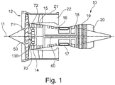
- a gas turbine engine is generally indicated at 10, having a principal and rotational axis 11.
- the engine 10 comprises, in axial flow series, an air intake 12, a propulsive fan 13 (could be more than one stage), a planetary gearbox 14, an intermediate pressure compressor 15, a high-pressure compressor 16, combustion equipment 17, a high-pressure turbine 18, an intermediate-pressure turbine 19 and an exhaust nozzle 20.
- a fan casing 21 generally surrounds the engine 10 and defines the intake 12.
- the gas turbine engine 10 works in the conventional manner so that air entering the intake 12 is accelerated by the propulsive fan 13 to produce two air flows: a first air flow into the intermediate pressure compressor 15 and a second air flow which passes through a bypass duct 22 to provide propulsive thrust.
- the intermediate pressure compressor 15 compresses the air flow directed into it before delivering that air to the high pressure compressor 16 where further compression takes place.
- the compressed air exhausted from the high-pressure compressor 16 is directed into the combustion equipment 17 where it is mixed with fuel and the mixture combusted.
- the resultant hot combustion products then expand through, and thereby drive the high pressure turbine 18 and intermediate pressure turbine 19 before being exhausted through the nozzle 20 to provide additional propulsive thrust.
- An intermediate pressure shaft 109 also drives the propulsive fan 13 via the planetary gearbox 14.
- the planetary gearbox 14 is a reduction gearbox in that it gears down the rate of rotation of the propulsive fan 13 by comparison with the intermediate pressure compressor 15 and intermediate pressure turbine 19.
- the planetary gearbox 14 is an epicyclic planetary gearbox having a static ring gear 72, rotating and orbiting planet gears 71 supported by a planet carrier driven by a rotating sun gear 70.
- Fig. 1 has a specific shaft arrangement which is understood not to be limiting.
- the embodiments described in the following can also work with a 2- or 3-shaft arrangement.
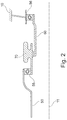
- Fig. 2 a baseline design of a connection between shafts 50, 60 and the planetary gearbox 14 is shown. For sake of simplicity only the sun gear 70 of the planetary gearbox 14 is shown.
- the sun gear 70 is driveably connected with a first shaft 50 driving the propulsive fan 13 (not shown in Fig. 2 ), in particular with first and second portions 52, 53 (see Fig. 3 ) of the first shaft 50.
- the planetary gearbox 14 On the input side the planetary gearbox 14 is connected to a second shaft 60, in particular the intermediate pressure shaft 60 of the gas turbine engine 10.
- the propulsive fan 13 is supported through a front load path and a rear load path, with the front load path comprising a first bearing 55 axially between the first shaft 50 and the sun gear 70.
- the first bearing 55 is an intershaft bearing.
- the rear load path comprises a second bearing 56 between the intermediate pressure shaft 60 and a fixed structure of the gas turbine engine 10.
- Fig. 3 an embodiment for supporting the propulsive fan 13 based on the baseline design shown in Fig. 2 is described.
- the shaft 50 on the output side of the planetary gearbox 14 comprises two portions, a first portion 52 and a second portion 53.
- a front bearing cone 51 is extending from a third bearing 57 at the transition point from the first portion 52 to the second portion 53.
- the propulsive fan 13 is supported through a front and a rear load path.
- the front load path comprises the third bearing 57 positioned on the shaft 50 between the propulsive fan 13 and the planetary gearbox 14.
- the propulsive fan 13 is connected to the first portion 52 of the shaft so that it is subjected in particular to a torque load.
- This torque is transmitted from the planetary gearbox 14 through a torque carrier coupling 54 which also carries a torque load.
- the torque generated in the turbine sections 19 is transmitted through the planetary gearbox 14 via the coupling 54 and the fan shaft 52 to the propulsive fan 13.
- the load from the third bearing 57 is transferred to the structure of the gas turbine engine 10 via the front bearing cone.
- the sun shaft i.e. the intermediate pressure shaft 60
- the sun shaft is supported by the second bearing 56 and engine structures 10 (see Fig. 2 ).
- the sun gear 70 is driven by the intermediate pressure shaft 60 through a spline connection 61.
- the sun gear 70 is integral with the intermediate pressure shaft 60.
- the sun gear 70 follows the deflection of the propulsive fan 13 and the subsequent fan shaft 52 deflection.
- the deflection of the fan shaft 50 induces a displacement into the sun gear 70 and into the output side of the torque carrier coupling 54.
- the sun gear 70 and planetary gears 71 move in unison with the shafts 50, 60 and remain in relative alignment.
- the rear load path of the propulsive fan 13 extends behind the planetary gearbox 14, maximising the stability of the structure.
Landscapes
- Engineering & Computer Science (AREA)
- Chemical & Material Sciences (AREA)
- Combustion & Propulsion (AREA)
- Mechanical Engineering (AREA)
- General Engineering & Computer Science (AREA)
- Retarders (AREA)
Claims (7)
- Moteur à turbine à gaz (10), en particulier un moteur d'avion, doté d'un dispositif de réacteur à réducteur, avec un ventilateur propulsif (13) et avec un multiplicateur planétaire (14) relié de manière entraînable à un premier arbre (50) sur le côté sortie du multiplicateur planétaire (14) et un second arbre (60) sur le côté entrée du multiplicateur planétaire (14), le ventilateur propulsif (13) étant soutenu par l'intermédiaire d'un trajet de charge avant axialement devant le multiplicateur planétaire (14) et d'un trajet de charge arrière axialement derrière le multiplicateur planétaire (14),
le trajet de charge avant comprenant un premier roulement (55) en tant que roulement intermédiaire entre le premier arbre (50) et une roue solaire (70),
le trajet de charge arrière comprenant un deuxième roulement (56) entre le second arbre (60) et une structure fixe du moteur à turbine à gaz (10), le second arbre (60) étant supporté par le deuxième roulement (56) et la structure de moteur, le premier arbre (50) comprenant une première partie (52) de l'arbre en tant que pièce de transmission de couple, et caractérisé en ce que
une pièce de transmission de couple comprend un accouplement de transmission de couple (54) relié au premier arbre (50) et à un support (71) du multiplicateur planétaire (14). - Moteur à turbine à gaz selon la revendication 1, le premier roulement (55) étant un roulement à rouleaux radial, en particulier un roulement à rouleaux coniques.
- Moteur à turbine à gaz selon la revendication 1 ou 2, le deuxième roulement (56) étant un roulement à rouleaux radial.
- Moteur à turbine à gaz selon au moins l'une des revendications précédentes, le second arbre (60), en particulier l'arbre de pression intermédiaire (60), étant relié à ou solidaire de la roue solaire (70) du multiplicateur planétaire (14).
- Moteur à turbine à gaz selon au moins l'une des revendications 1 à 3, la roue solaire (70) étant entraînée par l'intermédiaire d'une liaison cannelée (61) à travers le second arbre (60).
- Moteur à turbine à gaz selon au moins l'une des revendications précédentes, un troisième roulement (57) étant situé entre la première partie (52) du premier arbre (50) et une seconde partie (53) du premier arbre (50).
- Moteur à turbine à gaz selon la revendication 6, le troisième roulement (57) étant un roulement à rouleaux ou un roulement à rouleaux coniques.
Priority Applications (2)
| Application Number | Priority Date | Filing Date | Title |
|---|---|---|---|
| EP16189708.7A EP3296552B1 (fr) | 2016-09-20 | 2016-09-20 | Moteur à turbine à gaz doté d'un système de réacteur à réducteur |
| US15/708,716 US10502144B2 (en) | 2016-09-20 | 2017-09-19 | Gas turbine engine with a geared turbofan arrangement |
Applications Claiming Priority (1)
| Application Number | Priority Date | Filing Date | Title |
|---|---|---|---|
| EP16189708.7A EP3296552B1 (fr) | 2016-09-20 | 2016-09-20 | Moteur à turbine à gaz doté d'un système de réacteur à réducteur |
Publications (2)
| Publication Number | Publication Date |
|---|---|
| EP3296552A1 EP3296552A1 (fr) | 2018-03-21 |
| EP3296552B1 true EP3296552B1 (fr) | 2019-06-05 |
Family
ID=57046980
Family Applications (1)
| Application Number | Title | Priority Date | Filing Date |
|---|---|---|---|
| EP16189708.7A Active EP3296552B1 (fr) | 2016-09-20 | 2016-09-20 | Moteur à turbine à gaz doté d'un système de réacteur à réducteur |
Country Status (2)
| Country | Link |
|---|---|
| US (1) | US10502144B2 (fr) |
| EP (1) | EP3296552B1 (fr) |
Families Citing this family (3)
| Publication number | Priority date | Publication date | Assignee | Title |
|---|---|---|---|---|
| EP3587768A1 (fr) * | 2018-06-27 | 2020-01-01 | Rolls-Royce Deutschland Ltd & Co KG | Turbine à gaz |
| EP3587773B1 (fr) * | 2018-06-27 | 2022-06-08 | Rolls-Royce plc | Turbine à gaz |
| EP3611398B1 (fr) * | 2018-08-15 | 2022-01-26 | Rolls-Royce Deutschland Ltd & Co KG | Système de palier de stabilisation pour moteurs à double flux à engrenage |
Family Cites Families (24)
| Publication number | Priority date | Publication date | Assignee | Title |
|---|---|---|---|---|
| US3997042A (en) | 1975-11-05 | 1976-12-14 | General Motors Corporation | Aircraft engine coupling |
| US4270408A (en) | 1978-10-13 | 1981-06-02 | General Motors Corporation | Gear drive for gas turbine engine |
| US5533825A (en) | 1994-11-14 | 1996-07-09 | General Electric Company | Parabolically helical spline shaft coupling |
| FR2817912B1 (fr) * | 2000-12-07 | 2003-01-17 | Hispano Suiza Sa | Reducteur reprenant les efforts axiaux generes par la soufflante d'un turboreacteur |
| FR2841592B1 (fr) | 2002-06-27 | 2004-09-10 | Snecma Moteurs | Recentrage d'un rotor apres decouplage |
| US7921634B2 (en) * | 2006-10-31 | 2011-04-12 | General Electric Company | Turbofan engine assembly and method of assembling same |
| US7882693B2 (en) * | 2006-11-29 | 2011-02-08 | General Electric Company | Turbofan engine assembly and method of assembling same |
| US7716914B2 (en) | 2006-12-21 | 2010-05-18 | General Electric Company | Turbofan engine assembly and method of assembling same |
| US8191352B2 (en) * | 2008-12-19 | 2012-06-05 | General Electric Company | Geared differential speed counter-rotatable low pressure turbine |
| US8517672B2 (en) * | 2010-02-23 | 2013-08-27 | General Electric Company | Epicyclic gearbox |
| US9353690B2 (en) | 2010-06-21 | 2016-05-31 | Hamilton Sundstrand Corporation | Interface with mount features for precise alignment |
| US8881533B2 (en) | 2010-08-05 | 2014-11-11 | Rolls-Royce Corporation | Turbine engine |
| GB2487551A (en) | 2011-01-26 | 2012-08-01 | Rolls Royce Plc | Coupling having a threaded interconnector to limit torque |
| EP2535528B1 (fr) | 2011-06-17 | 2021-04-28 | Raytheon Technologies Corporation | Support de palier de turbosoufflante |
| DE102011084360B4 (de) * | 2011-10-12 | 2015-07-02 | Rolls-Royce Deutschland Ltd & Co Kg | Strömungsarbeitsmaschine |
| WO2014151785A1 (fr) * | 2013-03-15 | 2014-09-25 | United Technologies Corporation | Agencement paliers et boîtier de transmission de réacteur à double flux |
| US20160160875A1 (en) | 2013-08-26 | 2016-06-09 | United Technologies Corporation | Gas turbine engine with fan clearance control |
| EP2884056A1 (fr) | 2013-12-11 | 2015-06-17 | United Technologies Corporation | Systèmes et procédés impliquant de multiples chemins de couple pour des moteurs de turbines à gaz |
| FR3022890B1 (fr) | 2014-06-25 | 2018-01-05 | Snecma | Turbomachine comportant un moyen de decouplage d'une soufflante |
| EP2998557B1 (fr) | 2014-09-17 | 2017-07-12 | Airbus Operations, S.L. | Moteur hybride d'aéronef |
| GB201419859D0 (en) | 2014-11-07 | 2014-12-24 | Rolls Royce Plc | No title listed |
| GB201511606D0 (en) | 2015-07-02 | 2015-08-19 | Rolls Royce Plc | Drive shaft assembly |
| GB201516571D0 (en) | 2015-09-18 | 2015-11-04 | Rolls Royce Plc | A Coupling for a Geared Turbo Fan |
| GB201516570D0 (en) | 2015-09-18 | 2015-11-04 | Rolls Royce Plc | A Shafting Arrangement |
-
2016
- 2016-09-20 EP EP16189708.7A patent/EP3296552B1/fr active Active
-
2017
- 2017-09-19 US US15/708,716 patent/US10502144B2/en active Active
Non-Patent Citations (1)
| Title |
|---|
| None * |
Also Published As
| Publication number | Publication date |
|---|---|
| US20180080388A1 (en) | 2018-03-22 |
| EP3296552A1 (fr) | 2018-03-21 |
| US10502144B2 (en) | 2019-12-10 |
Similar Documents
| Publication | Publication Date | Title |
|---|---|---|
| EP1777406B1 (fr) | Turboréacteur ayant deux soufflantes contrarotatives | |
| EP2199568B1 (fr) | Turbine basse pression contra-rotative à vitesse différentielle munie d'un train épicycloïdal | |
| US7493754B2 (en) | Gas turbine engine assembly and methods of assembling same | |
| US7882693B2 (en) | Turbofan engine assembly and method of assembling same | |
| US7832193B2 (en) | Gas turbine engine assembly and methods of assembling same | |
| EP3144486B1 (fr) | Agencement d'arbre pour un moteur à turbine à gaz | |
| US7841165B2 (en) | Gas turbine engine assembly and methods of assembling same | |
| US7526913B2 (en) | Gas turbine engine assembly and methods of assembling same | |
| JP5111825B2 (ja) | 二重反転ファン組立体及び二重反転ファン組立体を備えるガスタービンエンジン組立体 | |
| US7493753B2 (en) | Gas turbine engine assembly and methods of assembling same | |
| US7490461B2 (en) | Gas turbine engine assembly and methods of assembling same | |
| US8292570B2 (en) | Low pressure turbine with counter-rotating drives for single spool | |
| EP1777370A2 (fr) | Ensemble moteur à turbine à gaz et procédé de montage d'un tel ensemble | |
| EP3495642B1 (fr) | Moteur à turbine à gaz | |
| EP3296552B1 (fr) | Moteur à turbine à gaz doté d'un système de réacteur à réducteur | |
| EP3696376B1 (fr) | Moteur à turbine à gaz |
Legal Events
| Date | Code | Title | Description |
|---|---|---|---|
| PUAI | Public reference made under article 153(3) epc to a published international application that has entered the european phase |
Free format text: ORIGINAL CODE: 0009012 |
|
| STAA | Information on the status of an ep patent application or granted ep patent |
Free format text: STATUS: THE APPLICATION HAS BEEN PUBLISHED |
|
| AK | Designated contracting states |
Kind code of ref document: A1 Designated state(s): AL AT BE BG CH CY CZ DE DK EE ES FI FR GB GR HR HU IE IS IT LI LT LU LV MC MK MT NL NO PL PT RO RS SE SI SK SM TR |
|
| AX | Request for extension of the european patent |
Extension state: BA ME |
|
| STAA | Information on the status of an ep patent application or granted ep patent |
Free format text: STATUS: REQUEST FOR EXAMINATION WAS MADE |
|
| 17P | Request for examination filed |
Effective date: 20180917 |
|
| RBV | Designated contracting states (corrected) |
Designated state(s): AL AT BE BG CH CY CZ DE DK EE ES FI FR GB GR HR HU IE IS IT LI LT LU LV MC MK MT NL NO PL PT RO RS SE SI SK SM TR |
|
| GRAP | Despatch of communication of intention to grant a patent |
Free format text: ORIGINAL CODE: EPIDOSNIGR1 |
|
| STAA | Information on the status of an ep patent application or granted ep patent |
Free format text: STATUS: GRANT OF PATENT IS INTENDED |
|
| RIC1 | Information provided on ipc code assigned before grant |
Ipc: F02C 7/36 20060101ALI20181205BHEP Ipc: F02K 3/06 20060101AFI20181205BHEP |
|
| INTG | Intention to grant announced |
Effective date: 20190109 |
|
| RIN1 | Information on inventor provided before grant (corrected) |
Inventor name: BONIFACE, DOMINIC |
|
| GRAS | Grant fee paid |
Free format text: ORIGINAL CODE: EPIDOSNIGR3 |
|
| GRAA | (expected) grant |
Free format text: ORIGINAL CODE: 0009210 |
|
| STAA | Information on the status of an ep patent application or granted ep patent |
Free format text: STATUS: THE PATENT HAS BEEN GRANTED |
|
| AK | Designated contracting states |
Kind code of ref document: B1 Designated state(s): AL AT BE BG CH CY CZ DE DK EE ES FI FR GB GR HR HU IE IS IT LI LT LU LV MC MK MT NL NO PL PT RO RS SE SI SK SM TR |
|
| REG | Reference to a national code |
Ref country code: GB Ref legal event code: FG4D |
|
| REG | Reference to a national code |
Ref country code: CH Ref legal event code: EP |
|
| REG | Reference to a national code |
Ref country code: AT Ref legal event code: REF Ref document number: 1140227 Country of ref document: AT Kind code of ref document: T Effective date: 20190615 |
|
| REG | Reference to a national code |
Ref country code: IE Ref legal event code: FG4D |
|
| REG | Reference to a national code |
Ref country code: DE Ref legal event code: R096 Ref document number: 602016014741 Country of ref document: DE |
|
| REG | Reference to a national code |
Ref country code: NL Ref legal event code: MP Effective date: 20190605 |
|
| REG | Reference to a national code |
Ref country code: LT Ref legal event code: MG4D |
|
| PG25 | Lapsed in a contracting state [announced via postgrant information from national office to epo] |
Ref country code: NO Free format text: LAPSE BECAUSE OF FAILURE TO SUBMIT A TRANSLATION OF THE DESCRIPTION OR TO PAY THE FEE WITHIN THE PRESCRIBED TIME-LIMIT Effective date: 20190905 Ref country code: HR Free format text: LAPSE BECAUSE OF FAILURE TO SUBMIT A TRANSLATION OF THE DESCRIPTION OR TO PAY THE FEE WITHIN THE PRESCRIBED TIME-LIMIT Effective date: 20190605 Ref country code: SE Free format text: LAPSE BECAUSE OF FAILURE TO SUBMIT A TRANSLATION OF THE DESCRIPTION OR TO PAY THE FEE WITHIN THE PRESCRIBED TIME-LIMIT Effective date: 20190605 Ref country code: FI Free format text: LAPSE BECAUSE OF FAILURE TO SUBMIT A TRANSLATION OF THE DESCRIPTION OR TO PAY THE FEE WITHIN THE PRESCRIBED TIME-LIMIT Effective date: 20190605 Ref country code: AL Free format text: LAPSE BECAUSE OF FAILURE TO SUBMIT A TRANSLATION OF THE DESCRIPTION OR TO PAY THE FEE WITHIN THE PRESCRIBED TIME-LIMIT Effective date: 20190605 Ref country code: ES Free format text: LAPSE BECAUSE OF FAILURE TO SUBMIT A TRANSLATION OF THE DESCRIPTION OR TO PAY THE FEE WITHIN THE PRESCRIBED TIME-LIMIT Effective date: 20190605 Ref country code: LT Free format text: LAPSE BECAUSE OF FAILURE TO SUBMIT A TRANSLATION OF THE DESCRIPTION OR TO PAY THE FEE WITHIN THE PRESCRIBED TIME-LIMIT Effective date: 20190605 |
|
| PG25 | Lapsed in a contracting state [announced via postgrant information from national office to epo] |
Ref country code: BG Free format text: LAPSE BECAUSE OF FAILURE TO SUBMIT A TRANSLATION OF THE DESCRIPTION OR TO PAY THE FEE WITHIN THE PRESCRIBED TIME-LIMIT Effective date: 20190905 Ref country code: RS Free format text: LAPSE BECAUSE OF FAILURE TO SUBMIT A TRANSLATION OF THE DESCRIPTION OR TO PAY THE FEE WITHIN THE PRESCRIBED TIME-LIMIT Effective date: 20190605 Ref country code: LV Free format text: LAPSE BECAUSE OF FAILURE TO SUBMIT A TRANSLATION OF THE DESCRIPTION OR TO PAY THE FEE WITHIN THE PRESCRIBED TIME-LIMIT Effective date: 20190605 Ref country code: GR Free format text: LAPSE BECAUSE OF FAILURE TO SUBMIT A TRANSLATION OF THE DESCRIPTION OR TO PAY THE FEE WITHIN THE PRESCRIBED TIME-LIMIT Effective date: 20190906 |
|
| REG | Reference to a national code |
Ref country code: AT Ref legal event code: MK05 Ref document number: 1140227 Country of ref document: AT Kind code of ref document: T Effective date: 20190605 |
|
| PG25 | Lapsed in a contracting state [announced via postgrant information from national office to epo] |
Ref country code: RO Free format text: LAPSE BECAUSE OF FAILURE TO SUBMIT A TRANSLATION OF THE DESCRIPTION OR TO PAY THE FEE WITHIN THE PRESCRIBED TIME-LIMIT Effective date: 20190605 Ref country code: SK Free format text: LAPSE BECAUSE OF FAILURE TO SUBMIT A TRANSLATION OF THE DESCRIPTION OR TO PAY THE FEE WITHIN THE PRESCRIBED TIME-LIMIT Effective date: 20190605 Ref country code: AT Free format text: LAPSE BECAUSE OF FAILURE TO SUBMIT A TRANSLATION OF THE DESCRIPTION OR TO PAY THE FEE WITHIN THE PRESCRIBED TIME-LIMIT Effective date: 20190605 Ref country code: EE Free format text: LAPSE BECAUSE OF FAILURE TO SUBMIT A TRANSLATION OF THE DESCRIPTION OR TO PAY THE FEE WITHIN THE PRESCRIBED TIME-LIMIT Effective date: 20190605 Ref country code: PT Free format text: LAPSE BECAUSE OF FAILURE TO SUBMIT A TRANSLATION OF THE DESCRIPTION OR TO PAY THE FEE WITHIN THE PRESCRIBED TIME-LIMIT Effective date: 20191007 Ref country code: CZ Free format text: LAPSE BECAUSE OF FAILURE TO SUBMIT A TRANSLATION OF THE DESCRIPTION OR TO PAY THE FEE WITHIN THE PRESCRIBED TIME-LIMIT Effective date: 20190605 Ref country code: NL Free format text: LAPSE BECAUSE OF FAILURE TO SUBMIT A TRANSLATION OF THE DESCRIPTION OR TO PAY THE FEE WITHIN THE PRESCRIBED TIME-LIMIT Effective date: 20190605 |
|
| PG25 | Lapsed in a contracting state [announced via postgrant information from national office to epo] |
Ref country code: IT Free format text: LAPSE BECAUSE OF FAILURE TO SUBMIT A TRANSLATION OF THE DESCRIPTION OR TO PAY THE FEE WITHIN THE PRESCRIBED TIME-LIMIT Effective date: 20190605 Ref country code: IS Free format text: LAPSE BECAUSE OF FAILURE TO SUBMIT A TRANSLATION OF THE DESCRIPTION OR TO PAY THE FEE WITHIN THE PRESCRIBED TIME-LIMIT Effective date: 20191005 Ref country code: SM Free format text: LAPSE BECAUSE OF FAILURE TO SUBMIT A TRANSLATION OF THE DESCRIPTION OR TO PAY THE FEE WITHIN THE PRESCRIBED TIME-LIMIT Effective date: 20190605 |
|
| REG | Reference to a national code |
Ref country code: DE Ref legal event code: R097 Ref document number: 602016014741 Country of ref document: DE |
|
| PG25 | Lapsed in a contracting state [announced via postgrant information from national office to epo] |
Ref country code: TR Free format text: LAPSE BECAUSE OF FAILURE TO SUBMIT A TRANSLATION OF THE DESCRIPTION OR TO PAY THE FEE WITHIN THE PRESCRIBED TIME-LIMIT Effective date: 20190605 |
|
| PLBE | No opposition filed within time limit |
Free format text: ORIGINAL CODE: 0009261 |
|
| STAA | Information on the status of an ep patent application or granted ep patent |
Free format text: STATUS: NO OPPOSITION FILED WITHIN TIME LIMIT |
|
| PG25 | Lapsed in a contracting state [announced via postgrant information from national office to epo] |
Ref country code: PL Free format text: LAPSE BECAUSE OF FAILURE TO SUBMIT A TRANSLATION OF THE DESCRIPTION OR TO PAY THE FEE WITHIN THE PRESCRIBED TIME-LIMIT Effective date: 20190605 Ref country code: DK Free format text: LAPSE BECAUSE OF FAILURE TO SUBMIT A TRANSLATION OF THE DESCRIPTION OR TO PAY THE FEE WITHIN THE PRESCRIBED TIME-LIMIT Effective date: 20190605 |
|
| 26N | No opposition filed |
Effective date: 20200306 |
|
| PG25 | Lapsed in a contracting state [announced via postgrant information from national office to epo] |
Ref country code: SI Free format text: LAPSE BECAUSE OF FAILURE TO SUBMIT A TRANSLATION OF THE DESCRIPTION OR TO PAY THE FEE WITHIN THE PRESCRIBED TIME-LIMIT Effective date: 20190605 Ref country code: MC Free format text: LAPSE BECAUSE OF FAILURE TO SUBMIT A TRANSLATION OF THE DESCRIPTION OR TO PAY THE FEE WITHIN THE PRESCRIBED TIME-LIMIT Effective date: 20190605 |
|
| REG | Reference to a national code |
Ref country code: CH Ref legal event code: PL |
|
| PG25 | Lapsed in a contracting state [announced via postgrant information from national office to epo] |
Ref country code: LI Free format text: LAPSE BECAUSE OF NON-PAYMENT OF DUE FEES Effective date: 20190930 Ref country code: LU Free format text: LAPSE BECAUSE OF NON-PAYMENT OF DUE FEES Effective date: 20190920 Ref country code: IE Free format text: LAPSE BECAUSE OF NON-PAYMENT OF DUE FEES Effective date: 20190920 Ref country code: CH Free format text: LAPSE BECAUSE OF NON-PAYMENT OF DUE FEES Effective date: 20190930 |
|
| REG | Reference to a national code |
Ref country code: BE Ref legal event code: MM Effective date: 20190930 |
|
| PG25 | Lapsed in a contracting state [announced via postgrant information from national office to epo] |
Ref country code: BE Free format text: LAPSE BECAUSE OF NON-PAYMENT OF DUE FEES Effective date: 20190930 |
|
| GBPC | Gb: european patent ceased through non-payment of renewal fee |
Effective date: 20200920 |
|
| PG25 | Lapsed in a contracting state [announced via postgrant information from national office to epo] |
Ref country code: CY Free format text: LAPSE BECAUSE OF FAILURE TO SUBMIT A TRANSLATION OF THE DESCRIPTION OR TO PAY THE FEE WITHIN THE PRESCRIBED TIME-LIMIT Effective date: 20190605 |
|
| PG25 | Lapsed in a contracting state [announced via postgrant information from national office to epo] |
Ref country code: HU Free format text: LAPSE BECAUSE OF FAILURE TO SUBMIT A TRANSLATION OF THE DESCRIPTION OR TO PAY THE FEE WITHIN THE PRESCRIBED TIME-LIMIT; INVALID AB INITIO Effective date: 20160920 Ref country code: MT Free format text: LAPSE BECAUSE OF FAILURE TO SUBMIT A TRANSLATION OF THE DESCRIPTION OR TO PAY THE FEE WITHIN THE PRESCRIBED TIME-LIMIT Effective date: 20190605 |
|
| PG25 | Lapsed in a contracting state [announced via postgrant information from national office to epo] |
Ref country code: GB Free format text: LAPSE BECAUSE OF NON-PAYMENT OF DUE FEES Effective date: 20200920 |
|
| PG25 | Lapsed in a contracting state [announced via postgrant information from national office to epo] |
Ref country code: MK Free format text: LAPSE BECAUSE OF FAILURE TO SUBMIT A TRANSLATION OF THE DESCRIPTION OR TO PAY THE FEE WITHIN THE PRESCRIBED TIME-LIMIT Effective date: 20190605 |
|
| P01 | Opt-out of the competence of the unified patent court (upc) registered |
Effective date: 20230528 |
|
| PGFP | Annual fee paid to national office [announced via postgrant information from national office to epo] |
Ref country code: DE Payment date: 20250926 Year of fee payment: 10 |
|
| PGFP | Annual fee paid to national office [announced via postgrant information from national office to epo] |
Ref country code: FR Payment date: 20250925 Year of fee payment: 10 |