EP3296510A2 - Additively deposited gas turbine engine cooling component - Google Patents
Additively deposited gas turbine engine cooling component Download PDFInfo
- Publication number
- EP3296510A2 EP3296510A2 EP17186119.8A EP17186119A EP3296510A2 EP 3296510 A2 EP3296510 A2 EP 3296510A2 EP 17186119 A EP17186119 A EP 17186119A EP 3296510 A2 EP3296510 A2 EP 3296510A2
- Authority
- EP
- European Patent Office
- Prior art keywords
- cooling
- substrate
- unitary structure
- turbine engine
- gas turbine
- Prior art date
- Legal status (The legal status is an assumption and is not a legal conclusion. Google has not performed a legal analysis and makes no representation as to the accuracy of the status listed.)
- Withdrawn
Links
- 238000001816 cooling Methods 0.000 title claims abstract description 212
- 239000000758 substrate Substances 0.000 claims abstract description 77
- 238000000034 method Methods 0.000 claims abstract description 32
- 238000000151 deposition Methods 0.000 claims abstract description 18
- 239000000463 material Substances 0.000 claims description 81
- 238000004519 manufacturing process Methods 0.000 claims description 27
- 230000009977 dual effect Effects 0.000 claims description 21
- 238000002485 combustion reaction Methods 0.000 claims description 11
- 238000009792 diffusion process Methods 0.000 claims description 6
- 229910045601 alloy Inorganic materials 0.000 claims description 4
- 239000000956 alloy Substances 0.000 claims description 4
- 229910052751 metal Inorganic materials 0.000 claims description 4
- 239000002184 metal Substances 0.000 claims description 4
- 239000000843 powder Substances 0.000 claims 1
- 239000007789 gas Substances 0.000 description 80
- 239000000203 mixture Substances 0.000 description 26
- 239000000654 additive Substances 0.000 description 25
- 230000000996 additive effect Effects 0.000 description 25
- 239000000945 filler Substances 0.000 description 20
- 238000003384 imaging method Methods 0.000 description 7
- 239000013070 direct material Substances 0.000 description 6
- 238000005266 casting Methods 0.000 description 5
- 238000010586 diagram Methods 0.000 description 5
- 238000002844 melting Methods 0.000 description 5
- 230000008018 melting Effects 0.000 description 5
- 230000008021 deposition Effects 0.000 description 4
- 238000003754 machining Methods 0.000 description 4
- 229910000601 superalloy Inorganic materials 0.000 description 4
- 239000000919 ceramic Substances 0.000 description 3
- 238000010276 construction Methods 0.000 description 3
- 238000002386 leaching Methods 0.000 description 3
- 238000005245 sintering Methods 0.000 description 3
- PXHVJJICTQNCMI-UHFFFAOYSA-N Nickel Chemical compound [Ni] PXHVJJICTQNCMI-UHFFFAOYSA-N 0.000 description 2
- 230000007547 defect Effects 0.000 description 2
- 239000011888 foil Substances 0.000 description 2
- 230000003647 oxidation Effects 0.000 description 2
- 238000007254 oxidation reaction Methods 0.000 description 2
- 239000007787 solid Substances 0.000 description 2
- 238000000149 argon plasma sintering Methods 0.000 description 1
- 239000011153 ceramic matrix composite Substances 0.000 description 1
- 239000011248 coating agent Substances 0.000 description 1
- 238000000576 coating method Methods 0.000 description 1
- 239000012809 cooling fluid Substances 0.000 description 1
- 239000000112 cooling gas Substances 0.000 description 1
- 239000013078 crystal Substances 0.000 description 1
- 238000001723 curing Methods 0.000 description 1
- 238000009826 distribution Methods 0.000 description 1
- 238000005553 drilling Methods 0.000 description 1
- 238000010894 electron beam technology Methods 0.000 description 1
- 238000001125 extrusion Methods 0.000 description 1
- 238000010438 heat treatment Methods 0.000 description 1
- 238000005304 joining Methods 0.000 description 1
- 239000007788 liquid Substances 0.000 description 1
- 230000000873 masking effect Effects 0.000 description 1
- 229910052759 nickel Inorganic materials 0.000 description 1
- 238000013021 overheating Methods 0.000 description 1
- 230000001590 oxidative effect Effects 0.000 description 1
- 239000011819 refractory material Substances 0.000 description 1
- 239000003870 refractory metal Substances 0.000 description 1
- 238000000926 separation method Methods 0.000 description 1
- 239000012720 thermal barrier coating Substances 0.000 description 1
- 238000007669 thermal treatment Methods 0.000 description 1
Images


Classifications
-
- F—MECHANICAL ENGINEERING; LIGHTING; HEATING; WEAPONS; BLASTING
- F01—MACHINES OR ENGINES IN GENERAL; ENGINE PLANTS IN GENERAL; STEAM ENGINES
- F01D—NON-POSITIVE DISPLACEMENT MACHINES OR ENGINES, e.g. STEAM TURBINES
- F01D25/00—Component parts, details, or accessories, not provided for in, or of interest apart from, other groups
- F01D25/08—Cooling; Heating; Heat-insulation
- F01D25/12—Cooling
-
- F—MECHANICAL ENGINEERING; LIGHTING; HEATING; WEAPONS; BLASTING
- F01—MACHINES OR ENGINES IN GENERAL; ENGINE PLANTS IN GENERAL; STEAM ENGINES
- F01D—NON-POSITIVE DISPLACEMENT MACHINES OR ENGINES, e.g. STEAM TURBINES
- F01D5/00—Blades; Blade-carrying members; Heating, heat-insulating, cooling or antivibration means on the blades or the members
- F01D5/12—Blades
- F01D5/14—Form or construction
- F01D5/18—Hollow blades, i.e. blades with cooling or heating channels or cavities; Heating, heat-insulating or cooling means on blades
- F01D5/182—Transpiration cooling
-
- B—PERFORMING OPERATIONS; TRANSPORTING
- B23—MACHINE TOOLS; METAL-WORKING NOT OTHERWISE PROVIDED FOR
- B23P—METAL-WORKING NOT OTHERWISE PROVIDED FOR; COMBINED OPERATIONS; UNIVERSAL MACHINE TOOLS
- B23P15/00—Making specific metal objects by operations not covered by a single other subclass or a group in this subclass
- B23P15/04—Making specific metal objects by operations not covered by a single other subclass or a group in this subclass turbine or like blades from several pieces
-
- F—MECHANICAL ENGINEERING; LIGHTING; HEATING; WEAPONS; BLASTING
- F01—MACHINES OR ENGINES IN GENERAL; ENGINE PLANTS IN GENERAL; STEAM ENGINES
- F01D—NON-POSITIVE DISPLACEMENT MACHINES OR ENGINES, e.g. STEAM TURBINES
- F01D5/00—Blades; Blade-carrying members; Heating, heat-insulating, cooling or antivibration means on the blades or the members
- F01D5/12—Blades
- F01D5/14—Form or construction
- F01D5/18—Hollow blades, i.e. blades with cooling or heating channels or cavities; Heating, heat-insulating or cooling means on blades
- F01D5/186—Film cooling
-
- F—MECHANICAL ENGINEERING; LIGHTING; HEATING; WEAPONS; BLASTING
- F01—MACHINES OR ENGINES IN GENERAL; ENGINE PLANTS IN GENERAL; STEAM ENGINES
- F01D—NON-POSITIVE DISPLACEMENT MACHINES OR ENGINES, e.g. STEAM TURBINES
- F01D9/00—Stators
- F01D9/02—Nozzles; Nozzle boxes; Stator blades; Guide conduits, e.g. individual nozzles
- F01D9/04—Nozzles; Nozzle boxes; Stator blades; Guide conduits, e.g. individual nozzles forming ring or sector
- F01D9/041—Nozzles; Nozzle boxes; Stator blades; Guide conduits, e.g. individual nozzles forming ring or sector using blades
-
- F—MECHANICAL ENGINEERING; LIGHTING; HEATING; WEAPONS; BLASTING
- F23—COMBUSTION APPARATUS; COMBUSTION PROCESSES
- F23R—GENERATING COMBUSTION PRODUCTS OF HIGH PRESSURE OR HIGH VELOCITY, e.g. GAS-TURBINE COMBUSTION CHAMBERS
- F23R3/00—Continuous combustion chambers using liquid or gaseous fuel
- F23R3/002—Wall structures
-
- F—MECHANICAL ENGINEERING; LIGHTING; HEATING; WEAPONS; BLASTING
- F23—COMBUSTION APPARATUS; COMBUSTION PROCESSES
- F23R—GENERATING COMBUSTION PRODUCTS OF HIGH PRESSURE OR HIGH VELOCITY, e.g. GAS-TURBINE COMBUSTION CHAMBERS
- F23R3/00—Continuous combustion chambers using liquid or gaseous fuel
- F23R3/005—Combined with pressure or heat exchangers
-
- F—MECHANICAL ENGINEERING; LIGHTING; HEATING; WEAPONS; BLASTING
- F23—COMBUSTION APPARATUS; COMBUSTION PROCESSES
- F23R—GENERATING COMBUSTION PRODUCTS OF HIGH PRESSURE OR HIGH VELOCITY, e.g. GAS-TURBINE COMBUSTION CHAMBERS
- F23R3/00—Continuous combustion chambers using liquid or gaseous fuel
- F23R3/02—Continuous combustion chambers using liquid or gaseous fuel characterised by the air-flow or gas-flow configuration
- F23R3/04—Air inlet arrangements
- F23R3/06—Arrangement of apertures along the flame tube
-
- F—MECHANICAL ENGINEERING; LIGHTING; HEATING; WEAPONS; BLASTING
- F05—INDEXING SCHEMES RELATING TO ENGINES OR PUMPS IN VARIOUS SUBCLASSES OF CLASSES F01-F04
- F05D—INDEXING SCHEME FOR ASPECTS RELATING TO NON-POSITIVE-DISPLACEMENT MACHINES OR ENGINES, GAS-TURBINES OR JET-PROPULSION PLANTS
- F05D2220/00—Application
- F05D2220/30—Application in turbines
- F05D2220/32—Application in turbines in gas turbines
-
- F—MECHANICAL ENGINEERING; LIGHTING; HEATING; WEAPONS; BLASTING
- F05—INDEXING SCHEMES RELATING TO ENGINES OR PUMPS IN VARIOUS SUBCLASSES OF CLASSES F01-F04
- F05D—INDEXING SCHEME FOR ASPECTS RELATING TO NON-POSITIVE-DISPLACEMENT MACHINES OR ENGINES, GAS-TURBINES OR JET-PROPULSION PLANTS
- F05D2230/00—Manufacture
- F05D2230/20—Manufacture essentially without removing material
-
- F—MECHANICAL ENGINEERING; LIGHTING; HEATING; WEAPONS; BLASTING
- F05—INDEXING SCHEMES RELATING TO ENGINES OR PUMPS IN VARIOUS SUBCLASSES OF CLASSES F01-F04
- F05D—INDEXING SCHEME FOR ASPECTS RELATING TO NON-POSITIVE-DISPLACEMENT MACHINES OR ENGINES, GAS-TURBINES OR JET-PROPULSION PLANTS
- F05D2230/00—Manufacture
- F05D2230/30—Manufacture with deposition of material
- F05D2230/31—Layer deposition
-
- F—MECHANICAL ENGINEERING; LIGHTING; HEATING; WEAPONS; BLASTING
- F05—INDEXING SCHEMES RELATING TO ENGINES OR PUMPS IN VARIOUS SUBCLASSES OF CLASSES F01-F04
- F05D—INDEXING SCHEME FOR ASPECTS RELATING TO NON-POSITIVE-DISPLACEMENT MACHINES OR ENGINES, GAS-TURBINES OR JET-PROPULSION PLANTS
- F05D2240/00—Components
- F05D2240/10—Stators
- F05D2240/12—Fluid guiding means, e.g. vanes
-
- F—MECHANICAL ENGINEERING; LIGHTING; HEATING; WEAPONS; BLASTING
- F05—INDEXING SCHEMES RELATING TO ENGINES OR PUMPS IN VARIOUS SUBCLASSES OF CLASSES F01-F04
- F05D—INDEXING SCHEME FOR ASPECTS RELATING TO NON-POSITIVE-DISPLACEMENT MACHINES OR ENGINES, GAS-TURBINES OR JET-PROPULSION PLANTS
- F05D2240/00—Components
- F05D2240/20—Rotors
- F05D2240/30—Characteristics of rotor blades, i.e. of any element transforming dynamic fluid energy to or from rotational energy and being attached to a rotor
-
- F—MECHANICAL ENGINEERING; LIGHTING; HEATING; WEAPONS; BLASTING
- F05—INDEXING SCHEMES RELATING TO ENGINES OR PUMPS IN VARIOUS SUBCLASSES OF CLASSES F01-F04
- F05D—INDEXING SCHEME FOR ASPECTS RELATING TO NON-POSITIVE-DISPLACEMENT MACHINES OR ENGINES, GAS-TURBINES OR JET-PROPULSION PLANTS
- F05D2240/00—Components
- F05D2240/35—Combustors or associated equipment
-
- F—MECHANICAL ENGINEERING; LIGHTING; HEATING; WEAPONS; BLASTING
- F05—INDEXING SCHEMES RELATING TO ENGINES OR PUMPS IN VARIOUS SUBCLASSES OF CLASSES F01-F04
- F05D—INDEXING SCHEME FOR ASPECTS RELATING TO NON-POSITIVE-DISPLACEMENT MACHINES OR ENGINES, GAS-TURBINES OR JET-PROPULSION PLANTS
- F05D2260/00—Function
- F05D2260/20—Heat transfer, e.g. cooling
- F05D2260/201—Heat transfer, e.g. cooling by impingement of a fluid
-
- F—MECHANICAL ENGINEERING; LIGHTING; HEATING; WEAPONS; BLASTING
- F05—INDEXING SCHEMES RELATING TO ENGINES OR PUMPS IN VARIOUS SUBCLASSES OF CLASSES F01-F04
- F05D—INDEXING SCHEME FOR ASPECTS RELATING TO NON-POSITIVE-DISPLACEMENT MACHINES OR ENGINES, GAS-TURBINES OR JET-PROPULSION PLANTS
- F05D2260/00—Function
- F05D2260/20—Heat transfer, e.g. cooling
- F05D2260/202—Heat transfer, e.g. cooling by film cooling
-
- F—MECHANICAL ENGINEERING; LIGHTING; HEATING; WEAPONS; BLASTING
- F05—INDEXING SCHEMES RELATING TO ENGINES OR PUMPS IN VARIOUS SUBCLASSES OF CLASSES F01-F04
- F05D—INDEXING SCHEME FOR ASPECTS RELATING TO NON-POSITIVE-DISPLACEMENT MACHINES OR ENGINES, GAS-TURBINES OR JET-PROPULSION PLANTS
- F05D2260/00—Function
- F05D2260/20—Heat transfer, e.g. cooling
- F05D2260/203—Heat transfer, e.g. cooling by transpiration cooling
-
- F—MECHANICAL ENGINEERING; LIGHTING; HEATING; WEAPONS; BLASTING
- F05—INDEXING SCHEMES RELATING TO ENGINES OR PUMPS IN VARIOUS SUBCLASSES OF CLASSES F01-F04
- F05D—INDEXING SCHEME FOR ASPECTS RELATING TO NON-POSITIVE-DISPLACEMENT MACHINES OR ENGINES, GAS-TURBINES OR JET-PROPULSION PLANTS
- F05D2260/00—Function
- F05D2260/94—Functionality given by mechanical stress related aspects such as low cycle fatigue [LCF] of high cycle fatigue [HCF]
Definitions
- the present disclosure relates to forming a cooled component in a gas turbine engine.
- Hot section components of a gas turbine engine may be operated in high temperature environments that may approach or exceed the softening or melting points of the materials of the components.
- Such components may include air foils including, for example turbine blades or vanes which may have one or more surfaces exposed high temperature combustion or exhaust gases flowing across the surface of the competent.
- Different techniques have been developed to assist with cooling of such components including, for example, application of a thermal barrier coating to the component, construction the component as single or dual wall structure, and passing a cooling fluid, such as air, across or through a portion of the component to aid in cooling of the component. Maintaining the efficiency and operation of such cooling systems is useful to facilitate engine performance and prevent over heating of the engine.
- the disclosure describes an example gas turbine engine component configured to separate a cooling air plenum from a heated gas environment.
- the gas turbine engine component includes a substrate defining a surface, and a unitary structure.
- the unitary structure includes a cooling region and a cover layer.
- the cover layer defines a hot wall surface configured to face the heated gas environment.
- the cooling region is disposed between the cover surface and the substrate.
- the cooling region includes a plurality of support structures extending between the cover layer and the surface of the substrate. At least some of the support structures define a respective bond surface bonded to the substrate at the surface of the substrate.
- the disclosure describes an example technique for fabricating a gas turbine engine component.
- the technique includes additively depositing a unitary structure on a surface of a substrate.
- the unitary structure includes a cooling region and a cover layer.
- the cover layer defines a hot wall surface configured to face the heated gas environment.
- the cooling region is disposed between the cover layer and the substrate and includes a plurality of support structures extending between the cover layer and the surface of the substrate. At least some of the support structures define respective bond surface bonded to the substrate at the surface.
- the disclosure generally describes gas turbine engine components configured to separate a cooling air plenum from a heated gas environment, in which the gas turbine engine component includes a substrate defining a surface and a unitary structure comprising a cooling region and a cover layer.
- the cover layer may define a hot wall surface configured to face the heated gas environment.
- the cooling region may be disposed between the cover layer and the substrate and includes a plurality of support structures extending between the cover layer and the surface of the substrate. At least some of the support structures define a respective bond surface bonded to the substrate at the surface of the substrate.
- the surface of the substrate may include a two-dimensional collection of points (flat surface), a three-dimensional collection of points whose cross section is a curve (curved surface), the boundary of any three-dimensional solid, or a continuous boundary dividing a three-dimensional space into two regions.
- Hot section components such as turbine surfaces, air foils, and flame tubes of a combustor of a gas turbine engine may be operated in high temperature gaseous environments.
- the temperature of the gaseous environments may approach or exceed the melting point or softening point of a material from which at least a portion of the component is formed.
- operating temperatures in a high pressure turbine section of a gas turbine engine may exceed melting or softening points of superalloy materials used in the high pressure turbine section, e.g., to form substrates of blades or vanes.
- the components may include a dual wall structure having a hot wall (e.g., coversheet), a cold wall (e.g., substrate), and a cooling region between the hot wall and the cold wall.
- the cooling region may include support structures between the hot wall and the cold wall.
- the cooling system may function by flowing relatively cold air from the compressor section of the gas turbine engine through cooling channels in the cooling region of the dual wall structure. These cooling channels may exhaust some or all of the cooling air through cooling apertures in the surface of the hot wall.
- the cooling air may help protect the component in such high temperature gaseous environments by, for example, reducing the relative temperature of the component, creating an insulating film of cooling air passing over the surface of the component exposed to the high temperature environment, or reducing the temperature of the gas within the high temperature environment.
- Dual wall structures may also reduce cooling airflow needs compared to a single wall structure, so that a greater volume of the airflow is available for operation of the turbine, for example, for combustion.
- Support structures may include features such as pins, fins, pedestals, or the like between the hot wall and the cold wall in the dual wall structure.
- the support structures also function as cooling features
- the dual wall structure may include additional cooling features (such as cooling channel) between the hot wall and the cold wall, or both.
- additional cooling features such as cooling channel
- Such cooling features may improve the effectiveness of cooling, for example, by providing additional surface area for convective cooling, by increasing conduction area to draw heat away from the hot wall, by routing cooling air through the space between the hot wall and cold wall in selected flow patterns, or the like.
- the effectiveness of the cooling features may increase as the cooling features are made finer due to an increase in exposed surface area to volume of the cooling features.
- integral casting with ceramic cores may utilize ceramic cores with very fine features, which are difficult to reliably and repeatably form, may have low manufacturing yields, may have limitations on feature size, and may present difficulties in inspecting support structures and cooling features between the hot wall and the cold wall to check for defects, blockages, or other failures.
- Using refractory metal cores may present similar difficulties in inspecting the support structures and cooling features to check for defects, blockages, or other failures.
- Diffusion bonding of separate spars and coversheets may present higher costs and increased complexity because of additional machining of castings prior to diffusion bonding and the use of multiple castings. Additionally, in some examples, bonding cycles may lead to some loss in material capability. While DMLS (direct metal laser sintering) may be used to fabricate separate cover sheets on spars having cooling features, the resulting components may have reduced material properties compared to single crystal alloys used in hot section components, for example, because of geometric discontinuities or compositional differences between separately fabricated cover sheets and spars, and may exhibit potential blockage of cooling circuits if filler material used to define voids or other channels is not fully removed after DMLS is complete. Aligning cooling holes in the hot wall with the underlying cooling pattern also may be difficult when fabricating the hot wall separately from the cold wall then joining the hot wall and cold wall.
- dual wall components may be formed by additively depositing a unitary structure on a substrate.
- the unitary structure may include the hot wall, the support structures, and, optionally, one or more separate cooling features.
- the disclosed examples and techniques described herein may be used to manufacture dual wall structures with, in various examples, intricate or fine cooling features, having higher yields compared to integral casting, having lower costs than diffusion bonded constructions, and/or providing better alignment between cooling holes in the hot wall and support structures or cooling features.
- Example dual wall components according to the disclosure may have a bond line between the cold wall and the hot wall that is farther from the hot wall compared to dual wall components manufactured using other techniques, which may lead to an increased working life and better mechanical stability.
- FIG. 1 is a conceptual cross-sectional view of an example component 10 for a gas turbine engine.
- Component 10 includes a unitary structure 12, and is configured to separate a cooling air plenum 14 from a heated gas environment 16 such that component 10 acts as a physical separation between the two environments.
- component 10 may include a hot section component for a gas turbine engine that receives or transfers cooling air as part of cooling system for a gas turbine engine.
- Component 10 may include, for example, components of a combustor such as a flame tube, combustion ring, the inner or outer casing, liner, guide vanes, or the like; components of a turbine section such as a nozzle guide vane, a turbine disc, a turbine blade, or the like; or another component associated with the air-cooling system of a gas turbine engine.
- component 10 may be constructed with a ceramic matrix composite, a superalloy substrate, or other materials used, for example, in the aviation or aerospace industry. However, component 10 may be formed of suitable materials other than those mentioned above.
- Cooling air plenum 14 and heated gas environment 16 may represent different flow paths, chambers, or regions within the gas turbine engine in which component 10 is installed.
- heated gas environment 16 may comprise the combustion chamber within the flame tube and cooling air plenum 14 may be the bypass/cooling air flow path that surrounds the exterior of the flame tube.
- heated gas environment 16 may represent the environment exterior to and flowing past the turbine blade or vane while cooling air plenum 14 may include one or more interior chambers within the turbine blade or vane representing part of the integral cooling system of the gas turbine engine.
- Unitary structure 12 includes a cover layer 18 and a cooling region 22.
- Unitary structure 12 is constructed of a composition 28 that may include any suitable material discussed above with reference to the construction of component 10 that may be deposited using additive manufacturing.
- composition 28 may include a superalloy, for example a nickel-based superalloy.
- Unitary structure 12 may be disposed on and attached to a major surface 31 of a substrate 30 of component 10. Cooling region 22 of unitary structure 12 may be disposed between cover layer 18 and substrate 30 such that cover layer 18 faces heated gas environment 16 and substrate 30 faces cooling air plenum 14. As such, in some examples, substrate 30 may be referred to as a cold wall and cover layer 18 may be referred to as a hot wall. In some examples, one or both of cover layer 18 and substrate 30 may define a thickness between about 0.014 inches and about 0.300 inches (e.g., about 0.36 mm to about 7.62 mm). In some examples, cooling region 22 may have a thickness between about 0.25 mm and about 7 mm.
- Cover layer 18 defines a hot wall surface 20 configured to face heated gas environment 16.
- Substrate 30 defines a cold wall surface 38 configured to face cooling air plenum 14.
- the terms "cold wall surface” and “hot wall surface” are used merely to orient which wall is adjacent to cooling air plenum 14 and which wall is adjacent to heated gas environment 16, respectively, and are not intended to limit the relative temperatures of the different environments or wall.
- cold wall surface 38 and cooling air plenum 14 may be described as “cold” sections compared to hot wall surface 20 and heated gas environment 16, the respective temperatures of cold wall surface 38 or cooling air plenum 14 may reach temperatures between about 390 °F to about 1830 °F (e.g., about 200 °C to about 1000 °C) during routine operation.
- Cooling region 22 may include a plurality of support structures 24.
- the plurality of support structures 24 may define a network of the plurality of cooling channels 26.
- the plurality of support structures 24 may include one or more of pedestals, columns, spires, raised features, or channel walls.
- the plurality of support structures 24 also may function as cooling features, e.g., for conducting heat from cover layer 18 toward substrate 30.
- cooling region 22 may include one or more additional cooling features, such as the plurality of cooling channels 26.
- the plurality of support structures 24 and, optionally, other cooling features may take on any useful configuration, size, shape, or pattern.
- the height of plurality of support structures 24 may be between about 0.25 mm and about 7 mm to define the thickness of cooling region 22.
- the plurality of support structures 24 may include a corrugated structure that defines the plurality of cooling channels 26 between the respective walls of the corrugated structure.
- the plurality of support structures 24 may also include one or more dams that act as zone dividers within the cooling region 22 thereby separating one cooling channel of the plurality of cooling channels 26 from another cooling channel of the plurality of cooling channels 26. The introduction of dams within cooling region 22 may assist with maintaining a more uniform temperature along hot wall surface 20 by controlling flow of cooling air within the plurality of cooling channels 26.
- the plurality of support structures 24 provides a conduit for heat transfer across hot wall surface 20 of cover layer 18 and cooling region 22 between cooling air plenum 14 and heated gas environment 16, as part of the air-cooling system for a gas turbine engine.
- Unitary structure 12 is bonded to substrate 30, for example, at bond surface 32 defined by cooling region 22, e.g., at respective bases of the plurality of support structures 24 opposite of cover layer 18. As seen in FIG. 1 , bond surface 32 is between cooling region 22 and substrate 30, such that bond surface 32 is on the opposite side of cooling region 22 from cover layer 18.
- the efficiency of heat transferred from heated gas environment 16 to cooling air plenum 14 across cooling region 22 may depend on a variety of factors including, but not limited to, the thermal conductivity of composition 28 of unitary structure 12, the total area of hot wall surface 20 of cover layer 18, the surface area defined by plurality of support structures 24 and plurality of cooling channels 26, the thermal conductivity of substrate 30, the total area of cold wall surface 38, the thermal conductivity at bond surface 32, and the size of cooling channels of the plurality of cooling channels 26.
- the thermal conductivity at bond surface 32 may be different (e.g., less) from the respective thermal conductivity of one or both of unitary structure 12 and substrate 30.
- bond surface 32 may act as a thermal resistor that inhibits the transfer of heat across bond surface 32, because of a lower thermal conductivity at bond surface 32, or because of local variations in composition or geometry.
- bond surface 32 has a lower thermal conductivity or acts as a thermal resistor
- positioning bond surface 32 closer to hot wall surface 20, for example between cover layer 18 and cooling region 22 may impede the transfer of heat from hot section part 14 to pedestals 16 compared to when bond surface 32 is positioned further from hot wall surface 20, for example between cooling region 22 and substrate 30.
- the net consequence of such a configuration may result in less heat being transferred to cooling air 32.
- positioning bond surface 32 farther away from hot wall surface 20, for example, between cooling region 22 and substrate 30 may improve the efficiency of heat transfer. Therefore, positioning bond surface 32 between cooling region 22 and substrate 30 may result in more heat being transferred from hot wall surface 20 across cooling region 22.
- cover layer 18 may define a plurality of cooling apertures 34, as shown in FIG. 2.
- FIG. 2 is conceptual cross-sectional view of an example component 10b for a gas turbine engine that includes a unitary structure 12b adjacent a substrate 30b.
- Unitary structure 12b may be substantially similar to unitary structure 12 discussed with reference to FIG. 1 above, while including a cover layer 18b substantially similar to cover layer 18 of FIG. 1 .
- cover layer 18b defines the plurality of cooling apertures 34.
- Cooling apertures 34 may extend between cooling region 22 and hot wall surface 20.
- substrate 30b may be substantially similar to substrate 30 discussed with reference to FIG. 1 above.
- substrate 30b may define a plurality of impingement apertures 36 extending between cooling region 22 and cold wall surface 38.
- the diameter of one or both of plurality of cooling apertures 34 and impingement apertures 36 may be between about 0.01 inches and about 0.12 inches (e.g., about 0.25 mm to about 3 mm).
- article 10b may be substantially similar to article 10 discussed above with reference to FIG. 1 , while further including one or both of plurality of cooling apertures 34 or plurality of impingement apertures 36.
- cooling air may pass from cooling air plenum 14 to heated gas environment 16 through one or both of the plurality of cooling apertures 34 or the plurality of impingement apertures 36.
- the cooling air may assist in maintaining the temperature of component 10b at a level lower than that of heated gas environment 16.
- the cooling air may enter heated gas environment 16 creating an insulating film of relatively cool gas along hot wall surface 20 of component 10b that allows hot wall surface 20 of component 10b to remain at a temperature less than that of the bulk temperature of heated gas environment 16.
- the cooling air may also at least partially mix with the gas of heated gas environment 16, thereby reducing the relative temperature of heated gas environment 16.
- the cooling region 22 may create a zoned temperature gradient between the respective regions of cooling air plenum 14 and heated gas environment 16.
- the cooling gas may act as a cooling reservoir that absorbs heat from component 10b as the gas passes through cooling apertures 24 or along one or more of the surfaces of component 10b, thereby dissipating the heat of component 10b and allowing the relative temperature of component to be maintained at a temperature less than that of heated gas environment 16.
- the cooling air may be supplied to component 10b (e.g., via cooling air plenum 14) at a pressure greater than the gas path pressure within heated gas environment 16.
- the pressure differential between cooling air plenum 12 and heated gas environment 16 may force cooling air 18 through the plurality of cooling apertures 34.
- the plurality of cooling apertures 34 may include film cooling holes that are shaped to reduce the use of cooling air.
- the plurality of cooling apertures 34 may be positioned in any suitable configuration and position about the surface of component 10b. For example, the plurality of cooling apertures 34 may be positioned along the leading edge of a gas turbine blade or vane.
- the plurality of cooling apertures 34 may define incidence angle less than 90 degrees, i.e., non-perpendicular, to the hot wall surface 20 of component 10a. In some examples the angle of incidence may be between about 10 degrees and about 75 degrees to hot wall surface 34 of component 10. In some such examples, adjusting the angle of incidence of hot wall surface 34 may assist with creating a cooling film of the cooling air along hot wall surface 20. Additionally, or alternatively, one or more of the plurality of cooling apertures 34 may include a fanned Coanda ramp path at the point of exit from hot wall surface 20 to help assist in the distribution or film characteristics of the cooling air as it exits a respective cooling aperture of the plurality of cooling apertures 34.
- component 10 or component 10b may be a dual wall component (e.g., as illustrated in FIGS. 1 and 2 ).
- substrate 30 may include a spar
- cover layer 18 may include a coversheet for the spar.
- Unitary structure 12 of component 10, or unitary structure 12b of component 10b may be fabricated using example techniques and example additive manufacturing systems, as described with reference to FIGS. 6 and 7 .
- an additive manufacturing system including a controller, a material stream and an energy beam may be used to fabricate unitary structure 12.
- the controller may direct the material stream and the energy beam along a tool path based on a digital representation of unitary structure 12.
- the energy beam may interact with portions of the material stream, for example, by fusing, solidifying, or sintering material from the material stream at a series of focal regions along the tool path, to deposit volumes of material along the tool path.
- the controller may deposit successive layers of material that ultimately form unitary structure 12.
- the controller may direct the material stream and the energy beam to deposit material in layers, forming the plurality of support structures 24 defining the plurality of cooling channels 26 in cooling region 22.
- the controller may direct deposition of material on surface 31 of substrate 30 in a predetermined build direction, for example, a vertical direction pointing away from surface 31.
- the controller may direct material along the build direction, beginning with layers of material on or adjacent surface 31 and then continuing to deposit layers that are successively farther away from surface 31.
- the controller may first direct the material stream and the energy beam to deposit layers of material forming the plurality of support structures 24, and then continue depositing material along the tool path forming layers of material supported by the plurality of supporting structures 24, that eventually form cover layer 18.
- additive manufacturing may be used to form cover layer 18 that is integrated, continuous, or otherwise unitary with cooling region 22.
- a filler composition may be deposited in a predetermined pattern.
- the filler composition may be deposited using extrusion, coating, stamping, masking, templating, or other suitable technique for depositing the filler composition in the predetermined pattern.
- the filler composition may be in the form of a paste, a liquid, a gel, a solid, or any other form that may support additively deposited material without collapsing.
- a layer of the filler composition of a predetermined thickness may be deposited on surface 31, followed by machining or removal of filler composition from predetermined portions of the layer.
- the predetermined pattern of filler composition may define the plurality of cooling channels 26, for example, by preventing the deposition of additively deposited material within a volume occupied by the filler composition.
- the controller may direct the deposition of additive material over the predetermined pattern defined by the filler composition, such that the predetermined pattern of filler composition defines the plurality of cooling channels as layers of additively deposited material are deposited over the predetermined pattern.
- the filler composition may include a filler or sacrificial material that may persist through the additive manufacturing, and be removed after the additive manufacturing is complete.
- the filler composition may be susceptible to at least one of heat, leaching, or oxidation.
- the filler composition may be removable from the plurality of cooling channels 26, for example, by subjecting the filler composition to at least one of a thermal treatment, leaching composition, or an oxidizing environment.
- the filler composition includes one or more of ceramic, metal, alloys, or other suitable refractory material.
- the plurality of cooling channels 26 may be occupied with the filler composition.
- part or whole of unitary structure 12 or component 10 may be subjected to one or more of heating, leaching, oxidation, or other suitable treatment for substantially removing the filler composition from unitary structure 12.
- additive manufacturing may be used to fabricate component 10, component 10b, or other example components including unitary structures.
- additive manufacturing may be used to fabricate turbine components described with reference to FIGS. 3-5 .
- FIG. 3 is a conceptual diagram of an example turbine airfoil component (e.g., turbine blade or vane) for use in a gas turbine engine.
- FIG. 3 illustrates an example turbine airfoil 50 that includes a plurality of cooling apertures 52 arranged on a hot section wall surface 54 of the airfoil.
- Turbine airfoil 50 may be a dual or multi-walled structure as described above with respect to FIGS 1 and 2 .
- FIG. 4 illustrates a cross-sectional view of an example dual wall turbine airfoil 70 that includes a plurality of cooling apertures 72 along a hot section wall 84 and a plurality of impingement apertures 80 along a cold section wall 86.
- dual wall turbine airfoil 70 may have substantially the same structural configuration as component 12, for example, including a cooling region including a plurality of support structures extending between hot section wall 84 and cold section wall 86, with the cooling region and hot section wall 84 forming a unitary structure.
- cooling air 78 may flow from cooling air plenum 74 through impingement apertures 80 into cooling channels 88 before exiting through cooling apertures 72 into heated gas environment 76.
- FIG. 5 illustrates a cross-sectional view of an example combustor 90 that includes a flame tube 92 (e.g., combustion chamber) with a sidewall defining a plurality of cooling apertures 94.
- the gases within the combustor post combustion (e.g., heated gas environment 96) may exceed about 1,800 °C, which may be too hot for introduction against the vanes and blade of the turbine (e.g., FIGS. 3 and 4 ).
- the combusted gases may be initially cooled prior to being introduced against the vanes and blade of the turbine by progressively introducing portions of the bypass air (e.g., cooling air 98) into heated gas environment 96 of flame tube 92 via ingress through plurality of cooling aperture 94 strategically position around flame tube 94, fluidly connecting cooling air 98 within cooling air plenum 100 with heated gas environment 96.
- bypass air e.g., cooling air 98
- combustor 90 includes a dual wall structure having substantially the same structural configuration as component 12, for example, including a cooling region including a plurality of support structures extending between a surface adjacent heated gas environment 96 and a surface adjacent cooling air 98, with the cooling region and the layer adjacent heated gas environment 96 forming a unitary structure.
- cooling air 98 may intimately mix with the combusted gases to decease the resultant temperature of the volume of heated gas environment 96. Additionally, or alternatively, cooling air 98 may form an insulating cooling air film along the interior surface (e.g., hot section surface) of flame tube 92.
- the wall of flame tube may include a dual wall (e.g., component 10 or 10b) structure.
- Example gas turbine engine components including a unitary structure and a substrate have been described above.
- additive manufacturing may be used to fabricate a unitary structure including an integrated or continuous unitary cover layer and cooling region.
- example components may be fabricated using additive manufacturing, for example, using the example system of FIG. 6 , and the example technique of FIG. 7 , as discussed below.
- example components described with reference to FIGS. 1-5 above may be fabricated using other suitable example systems or other suitable example techniques.
- FIG. 6 is a schematic and conceptual block diagram of an example system 110 for fabricating a gas turbine engine component that includes a unitary structure 112 disposed on a substrate 130.
- Example system 110 includes a computing device 116 that may control an additive manufacturing tool 114 for fabricating unitary structure 112 that includes a material 120.
- computing device 116 may generate or store a digital representation 112a of unitary structure 112, or of the gas turbine engine component that includes unitary structure 112.
- computing device 116 may control additive manufacturing tool 114 to fabricate the component including unitary structure 112 based on digital representation 112a.
- additive manufacturing tool 114 may include a controller 134 for controlling one or more of a material source 124, and energy source 128, and an imaging device 132.
- Computing device 116 may send control signals to controller 134 for controlling additive manufacturing tool 114.
- computing device 116 may send operational signals to and receive status signals from controller 134 to control and monitor the operation of additive manufacturing tool 114.
- computing device 116 may not control additive manufacturing tool 114, and controller 134 may be configured to receive signals indicative of digital representation 112a from computing device 116 and to control additive manufacturing tool 114 based on digital representation 112a to fabricate the component including unitary structure 112.
- controller 134 may control material source 124 of additive manufacturing tool 114 to direct a material stream 126 including material 120 at a build location on partially-fabricated component 112, which is carried on a build platform 122, or at an initial build location on a region of substrate 130 on build platform 22.
- material 120 may include metal or alloy, or any suitable material composition discussed above with reference to component 10 or unitary structure 12 of FIG. 1 .
- Controller 134 also may control energy source 128 to direct an energy beam 127 at the build location.
- Energy beam 127 may interact with material 120 from material stream 126 at the build location, for example, by fusing, melting, sintering, curing, solidifying or otherwise modifying material 120 at the build location to cause material 120 to be joined to other material of component 112 at the build location, or to material of substrate 130.
- Energy beam 127 may include any energy, for example, ultraviolet light, electron beam, plasma, or laser, that may interact with material 120 to change a state of material 120.
- energy beam 127 may be focusable or directable towards material 120 in material stream 126.
- the build location at which energy beam 127 interacts with material stream 126 is adjacent an existing surface of unitary structure 112 such that material 120 is added to unitary structure 112.
- controller 134 may control energy source 128 to emit a diffuse energy beam, or a patterned array of beams, for example, a light pattern.
- the build location may change as unitary structure 112 is fabricated, for example, along regions or surfaces of partly fabricated unitary structure 112.
- controller 134 may cause additive manufacturing tool 114 to fabricate unitary structure 112 by depositing material 120 at different build locations along a tool path, so that material 120 is ultimately deposited along a predetermined build direction, for example a vertical build direction upwards (for example, against a gravitational force) or downwards (for example, toward a gravitational force).
- a predetermined build direction for example a vertical build direction upwards (for example, against a gravitational force) or downwards (for example, toward a gravitational force).
- build platform 122 may remain stationary as unitary structure 112 is fabricated.
- build platform 122 may be movable or rotatable, for example, along multiple axis, and controller 134 may control the position of build platform 122.
- controller 134 may successively move build platform 122 against the build direction, or to change the build location by changing the orientation of build platform 122, and that of unitary structure 112, relative to material stream 126 and energy beam 127.
- controller 134 may separately control material source 124 and energy source 128, for example, by separately controlling material source 124 to direct material stream 126 to deposit a layer or volume of material 120, and then controlling energy source 128 to direct energy beam 127 along a series of build locations within the deposited layer or volume of material 120 to energize material 120 at the build locations to fabricate unitary structure 112. Therefore, controller 134 may direct build location along a two-dimensional or three-dimensional tool path to fabricate unitary structure 112 based on digital representation 112a.
- controller 134 may control imaging device 132 to image surfaces or regions or volumes of one or more of unitary structure 112, the build location, or platform 122 to generate respective build images periodically or continuously. Controller 134 may periodically or continuously compare the build images with the digital representation 112a to verify that unitary structure 112 substantially conforms (e.g., conforms or nearly conforms) to digital representation 112a. In some examples, controller 134 may control one or more of material source 124, energy source 128, and build platform 122 based on the build images and the digital representation 112a.
- controller 134 may be configured to control build platform 122 and material source 124, energy source 128, and/or imaging device 132 to translate and/or rotate along at least one axis to position unitary structure 112 relative to material stream 126, energy beam 127, and/or imaging device 132.
- Positioning unitary structure 112 relative to material stream 126, energy beam 127, and/or imaging device 132 may include positioning a predetermined surface (e.g., a surface to which material is to be added) of unitary structure 112 in a predetermined orientation relative to material source 124, energy source 128, and/or imaging device 132, so that material is added in regions or volumes defined by digital representation 112a.
- additive manufacturing tool 114 may not include controller 134, and computing device 112 may control one or more of material source 124, energy source 128, imaging device 132, and build platform 122, instead of controller 134.
- Example system 110 discussed above may be used to fabricate example components described above with reference to FIGS. 1-5 . However, example system 110 may be used to fabricate other example components according to the disclosure.
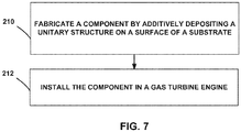
- FIG. 7 is a flow diagram illustrating an example technique for forming a component of a gas turbine engine that includes a unitary structure including a cover layer and a cooling region. While the below technique of FIG. 7 is described with respect to components 10 and 10b of FIGS. 1 and 2 , and system 110 of FIG. 6 , it will be understood from the context of the specification that the technique of FIG. 7 may be implemented using other systems, or applied to other components of a gas turbine engine including, for example, components 50, 70, and 90, flame tubes, combustor rings, combustion chambers, casings of combustion chambers, turbine blades, turbine vanes, or the like; all of which are envisioned within the scope of the technique of FIG. 7 .
- the example technique of FIG. 7 includes fabricating component 10 by additively depositing a unitary structure 12 on a surface of a substrate 30 (210).
- unitary structure 12 includes cooling region 22 opposing cover layer 18. Cooling region 22 is disposed between cover layer 18 and substrate 30.
- Component 10 is configured to separate cooling air plenum 14 from heated gas environment 16.
- Cover layer 18 defines a hot wall surface 20 configured to face heated gas environment 16.
- Cooling region 22 defines the plurality of support structures 24 extending between cover layer 18 and surface 31 of substrate 30. Cooling region 22 defines bond surface 32 bonded to substrate 30.
- additively depositing the unitary structure includes directing material stream 126 and energy stream 127 at a focal region on a surface of substrate 122, or on a surface of partially fabricated unitary structure 112.
- additively depositing the unitary structure includes moving the focal region along a predetermined path.
- controller 134 may control energy beam 127 and material stream 126 such that energy beam 127 interacts with portions, volumes, or packets of material from material stream 126, for example, by fusing, solidifying, or sintering material from material stream 126 at a series of focal regions along the tool path, to deposit volumes of material along the tool path.
- controller 134 may deposit successive layers of material that ultimately form unitary structure 12.
- controller 134 may direct material stream 126 and energy beam 127 to deposit material in layers, forming the plurality of support structures 24 defining the plurality of cooling channels 26 in cooling region 22.
- controller 134 may direct deposition of material on surface 31 of substrate 30 in a predetermined build direction, for example, a vertical direction pointing away from surface 31.
- controller 134 may direct material along the build direction, beginning with layers of material on or adjacent surface 31 and then continuing to deposit layers that are successively farther away from surface 31.
- controller 134 may first direct material stream 126 and energy beam 127 to deposit layers of material forming the plurality of support structures 24, and then continue depositing material along the tool path forming layers of material supported by the plurality of supporting structures 24, that eventually form cover layer 18.
- digital representation 112a may include a representation of plurality of cooling apertures 34.
- Controller 134 may direct material stream 126 and laser beam 128 around regions defining cooling apertures 34, for example, by depositing layers that define successive cross-sections of predetermined channels that eventually define cooling apertures 34.
- system 110 may fabricate cover layer 18 that defines plurality of cooling apertures 34.
- cover layer 18 may be fabricated without cooling apertures 34, and cooling apertures may be formed after the additive manufacturing, for example, by machining or drilling apertures through cover layer 18.
- example techniques may include additive manufacturing to form cover layer 18 that is integrated, continuous, or otherwise unitary with cooling region 22.
- component 10 may be installed in a gas turbine engine (212) and connected to the air cooling system of the engine.
- installing the unitary structure includes bonding the component to a gas turbine engine component surface.
- bonding the component includes diffusion bonding.
- installing the unitary structure includes connecting the component to an air-cooling system of the gas turbine engine.
- example technique of FIG. 7 may be used to fabricate example components described above with reference to FIGS. 1-5 and with reference to example system 110 of FIG. 6 , the example technique of FIG. 7 may be used to fabricate other example components.
Landscapes
- Engineering & Computer Science (AREA)
- Mechanical Engineering (AREA)
- General Engineering & Computer Science (AREA)
- Chemical & Material Sciences (AREA)
- Combustion & Propulsion (AREA)
- Turbine Rotor Nozzle Sealing (AREA)
Abstract
Description
- The present disclosure relates to forming a cooled component in a gas turbine engine.
- Hot section components of a gas turbine engine may be operated in high temperature environments that may approach or exceed the softening or melting points of the materials of the components. Such components may include air foils including, for example turbine blades or vanes which may have one or more surfaces exposed high temperature combustion or exhaust gases flowing across the surface of the competent. Different techniques have been developed to assist with cooling of such components including, for example, application of a thermal barrier coating to the component, construction the component as single or dual wall structure, and passing a cooling fluid, such as air, across or through a portion of the component to aid in cooling of the component. Maintaining the efficiency and operation of such cooling systems is useful to facilitate engine performance and prevent over heating of the engine.
- In some examples, the disclosure describes an example gas turbine engine component configured to separate a cooling air plenum from a heated gas environment. The gas turbine engine component includes a substrate defining a surface, and a unitary structure. The unitary structure includes a cooling region and a cover layer. The cover layer defines a hot wall surface configured to face the heated gas environment. The cooling region is disposed between the cover surface and the substrate. The cooling region includes a plurality of support structures extending between the cover layer and the surface of the substrate. At least some of the support structures define a respective bond surface bonded to the substrate at the surface of the substrate.
- In some examples, the disclosure describes an example technique for fabricating a gas turbine engine component. The technique includes additively depositing a unitary structure on a surface of a substrate. The unitary structure includes a cooling region and a cover layer. The cover layer defines a hot wall surface configured to face the heated gas environment. The cooling region is disposed between the cover layer and the substrate and includes a plurality of support structures extending between the cover layer and the surface of the substrate. At least some of the support structures define respective bond surface bonded to the substrate at the surface.
- The details of one or more examples are set forth in the accompanying drawings and the description below. Other features, objects, and advantages will be apparent from the description and drawings, and from the claims.
-
FIG. 1 is a conceptual cross-sectional view of an example component for a gas turbine engine that includes a unitary structure bonded to a surface of a substrate. -
FIG. 2 is conceptual cross-sectional view of an example component for a gas turbine engine that includes a unitary structure bonded to a surface of a substrate, where a cover layer of the unitary structure defines cooling apertures. -
FIG. 3 is a conceptual diagram of an example turbine blade for use in a gas turbine engine. -
FIG. 4 is a conceptual cross-sectional view of an example dual walled turbine blade for use in a gas turbine engine that includes a unitary structure bonded to a surface of a substrate. -
FIG. 5 is a cross-sectional view of an example combustor that includes a flame tube with a sidewall. -
FIG. 6 is a schematic and conceptual block diagram of an example system for fabricating a gas turbine engine component that includes a unitary structure bonded to a substrate. -
FIG. 7 is a conceptual flow chart of an example technique for fabricating a gas turbine engine component that includes a unitary structure bonded to a substrate. - The disclosure generally describes gas turbine engine components configured to separate a cooling air plenum from a heated gas environment, in which the gas turbine engine component includes a substrate defining a surface and a unitary structure comprising a cooling region and a cover layer. The cover layer may define a hot wall surface configured to face the heated gas environment. The cooling region may be disposed between the cover layer and the substrate and includes a plurality of support structures extending between the cover layer and the surface of the substrate. At least some of the support structures define a respective bond surface bonded to the substrate at the surface of the substrate. The surface of the substrate may include a two-dimensional collection of points (flat surface), a three-dimensional collection of points whose cross section is a curve (curved surface), the boundary of any three-dimensional solid, or a continuous boundary dividing a three-dimensional space into two regions. By disposing the bond between the unitary structure and the substrate at the interface between the support structures and the substrate, the gas turbine engine components may possess an increased working life and better mechanical stability compared to components in which the bond interface is between the cover layer and the support structures. While not wishing to be bound by any specific theory, it is believed that this is due to the bond interface potentially introducing thermal resistivity. By moving the bond interface further from the hot wall surface, more of the unitary structure is exposed to cooling air, which may lead to increased heat transfer from the unitary structure to the cooling air.
- Hot section components, such as turbine surfaces, air foils, and flame tubes of a combustor of a gas turbine engine may be operated in high temperature gaseous environments. In some examples, the temperature of the gaseous environments may approach or exceed the melting point or softening point of a material from which at least a portion of the component is formed. For example, operating temperatures in a high pressure turbine section of a gas turbine engine may exceed melting or softening points of superalloy materials used in the high pressure turbine section, e.g., to form substrates of blades or vanes.
- In some examples, to reduce or substantially prevent melting or softening of the engine components, the components may include a dual wall structure having a hot wall (e.g., coversheet), a cold wall (e.g., substrate), and a cooling region between the hot wall and the cold wall. The cooling region may include support structures between the hot wall and the cold wall. In some examples, the cooling system may function by flowing relatively cold air from the compressor section of the gas turbine engine through cooling channels in the cooling region of the dual wall structure. These cooling channels may exhaust some or all of the cooling air through cooling apertures in the surface of the hot wall. In some examples, the cooling air may help protect the component in such high temperature gaseous environments by, for example, reducing the relative temperature of the component, creating an insulating film of cooling air passing over the surface of the component exposed to the high temperature environment, or reducing the temperature of the gas within the high temperature environment. Dual wall structures may also reduce cooling airflow needs compared to a single wall structure, so that a greater volume of the airflow is available for operation of the turbine, for example, for combustion.
- Support structures may include features such as pins, fins, pedestals, or the like between the hot wall and the cold wall in the dual wall structure. In some examples, the support structures also function as cooling features, the dual wall structure may include additional cooling features (such as cooling channel) between the hot wall and the cold wall, or both. Such cooling features may improve the effectiveness of cooling, for example, by providing additional surface area for convective cooling, by increasing conduction area to draw heat away from the hot wall, by routing cooling air through the space between the hot wall and cold wall in selected flow patterns, or the like. In some examples, the effectiveness of the cooling features may increase as the cooling features are made finer due to an increase in exposed surface area to volume of the cooling features.
- While techniques such as integral casting, diffusion bonding, and machining may be used to fabricate dual wall structures, these techniques have drawbacks. For example, integral casting with ceramic cores may utilize ceramic cores with very fine features, which are difficult to reliably and repeatably form, may have low manufacturing yields, may have limitations on feature size, and may present difficulties in inspecting support structures and cooling features between the hot wall and the cold wall to check for defects, blockages, or other failures. Using refractory metal cores may present similar difficulties in inspecting the support structures and cooling features to check for defects, blockages, or other failures.
- Diffusion bonding of separate spars and coversheets may present higher costs and increased complexity because of additional machining of castings prior to diffusion bonding and the use of multiple castings. Additionally, in some examples, bonding cycles may lead to some loss in material capability. While DMLS (direct metal laser sintering) may be used to fabricate separate cover sheets on spars having cooling features, the resulting components may have reduced material properties compared to single crystal alloys used in hot section components, for example, because of geometric discontinuities or compositional differences between separately fabricated cover sheets and spars, and may exhibit potential blockage of cooling circuits if filler material used to define voids or other channels is not fully removed after DMLS is complete. Aligning cooling holes in the hot wall with the underlying cooling pattern also may be difficult when fabricating the hot wall separately from the cold wall then joining the hot wall and cold wall.
- In some examples according to the disclosure, dual wall components may be formed by additively depositing a unitary structure on a substrate. The unitary structure may include the hot wall, the support structures, and, optionally, one or more separate cooling features. The disclosed examples and techniques described herein may be used to manufacture dual wall structures with, in various examples, intricate or fine cooling features, having higher yields compared to integral casting, having lower costs than diffusion bonded constructions, and/or providing better alignment between cooling holes in the hot wall and support structures or cooling features. Example dual wall components according to the disclosure may have a bond line between the cold wall and the hot wall that is farther from the hot wall compared to dual wall components manufactured using other techniques, which may lead to an increased working life and better mechanical stability.
-
FIG. 1 is a conceptual cross-sectional view of anexample component 10 for a gas turbine engine.Component 10 includes aunitary structure 12, and is configured to separate acooling air plenum 14 from a heatedgas environment 16 such thatcomponent 10 acts as a physical separation between the two environments. - In some examples,
component 10 may include a hot section component for a gas turbine engine that receives or transfers cooling air as part of cooling system for a gas turbine engine.Component 10 may include, for example, components of a combustor such as a flame tube, combustion ring, the inner or outer casing, liner, guide vanes, or the like; components of a turbine section such as a nozzle guide vane, a turbine disc, a turbine blade, or the like; or another component associated with the air-cooling system of a gas turbine engine. In some examples,component 10 may be constructed with a ceramic matrix composite, a superalloy substrate, or other materials used, for example, in the aviation or aerospace industry. However,component 10 may be formed of suitable materials other than those mentioned above. - Cooling
air plenum 14 andheated gas environment 16 may represent different flow paths, chambers, or regions within the gas turbine engine in whichcomponent 10 is installed. For example, in some examples in whichcomponent 10 is a flame tube of a combustor of a gas turbine engine,heated gas environment 16 may comprise the combustion chamber within the flame tube and coolingair plenum 14 may be the bypass/cooling air flow path that surrounds the exterior of the flame tube. In some examples in whichcomponent 10 is a turbine blade or vane,heated gas environment 16 may represent the environment exterior to and flowing past the turbine blade or vane while coolingair plenum 14 may include one or more interior chambers within the turbine blade or vane representing part of the integral cooling system of the gas turbine engine. -
Unitary structure 12 includes acover layer 18 and acooling region 22.Unitary structure 12 is constructed of acomposition 28 that may include any suitable material discussed above with reference to the construction ofcomponent 10 that may be deposited using additive manufacturing. In some examples,composition 28 may include a superalloy, for example a nickel-based superalloy. -
Unitary structure 12 may be disposed on and attached to amajor surface 31 of asubstrate 30 ofcomponent 10.Cooling region 22 ofunitary structure 12 may be disposed betweencover layer 18 andsubstrate 30 such thatcover layer 18 facesheated gas environment 16 andsubstrate 30 faces coolingair plenum 14. As such, in some examples,substrate 30 may be referred to as a cold wall andcover layer 18 may be referred to as a hot wall. In some examples, one or both ofcover layer 18 andsubstrate 30 may define a thickness between about 0.014 inches and about 0.300 inches (e.g., about 0.36 mm to about 7.62 mm). In some examples, coolingregion 22 may have a thickness between about 0.25 mm and about 7 mm. -
Cover layer 18 defines ahot wall surface 20 configured to faceheated gas environment 16.Substrate 30 defines acold wall surface 38 configured to facecooling air plenum 14. The terms "cold wall surface" and "hot wall surface" are used merely to orient which wall is adjacent to coolingair plenum 14 and which wall is adjacent toheated gas environment 16, respectively, and are not intended to limit the relative temperatures of the different environments or wall. For example, whilecold wall surface 38 and coolingair plenum 14 may be described as "cold" sections compared tohot wall surface 20 andheated gas environment 16, the respective temperatures ofcold wall surface 38 or coolingair plenum 14 may reach temperatures between about 390 °F to about 1830 °F (e.g., about 200 °C to about 1000 °C) during routine operation. -
Cooling region 22 may include a plurality ofsupport structures 24. The plurality ofsupport structures 24 may define a network of the plurality ofcooling channels 26. For example, the plurality ofsupport structures 24 may include one or more of pedestals, columns, spires, raised features, or channel walls. The plurality ofsupport structures 24 also may function as cooling features, e.g., for conducting heat fromcover layer 18 towardsubstrate 30. In some examples, coolingregion 22 may include one or more additional cooling features, such as the plurality ofcooling channels 26. The plurality ofsupport structures 24 and, optionally, other cooling features, may take on any useful configuration, size, shape, or pattern. In some such examples, the height of plurality ofsupport structures 24 may be between about 0.25 mm and about 7 mm to define the thickness of coolingregion 22. - In some examples, the plurality of
support structures 24 may include a corrugated structure that defines the plurality ofcooling channels 26 between the respective walls of the corrugated structure. In some examples, the plurality ofsupport structures 24 may also include one or more dams that act as zone dividers within thecooling region 22 thereby separating one cooling channel of the plurality ofcooling channels 26 from another cooling channel of the plurality ofcooling channels 26. The introduction of dams within coolingregion 22 may assist with maintaining a more uniform temperature alonghot wall surface 20 by controlling flow of cooling air within the plurality ofcooling channels 26. Thus, in some examples, the plurality ofsupport structures 24 provides a conduit for heat transfer acrosshot wall surface 20 ofcover layer 18 andcooling region 22 between coolingair plenum 14 andheated gas environment 16, as part of the air-cooling system for a gas turbine engine. -
Unitary structure 12 is bonded tosubstrate 30, for example, atbond surface 32 defined by coolingregion 22, e.g., at respective bases of the plurality ofsupport structures 24 opposite ofcover layer 18. As seen inFIG. 1 ,bond surface 32 is between coolingregion 22 andsubstrate 30, such thatbond surface 32 is on the opposite side of coolingregion 22 fromcover layer 18. - The efficiency of heat transferred from
heated gas environment 16 to coolingair plenum 14 across coolingregion 22 may depend on a variety of factors including, but not limited to, the thermal conductivity ofcomposition 28 ofunitary structure 12, the total area ofhot wall surface 20 ofcover layer 18, the surface area defined by plurality ofsupport structures 24 and plurality ofcooling channels 26, the thermal conductivity ofsubstrate 30, the total area ofcold wall surface 38, the thermal conductivity atbond surface 32, and the size of cooling channels of the plurality ofcooling channels 26. For example, the thermal conductivity atbond surface 32 may be different (e.g., less) from the respective thermal conductivity of one or both ofunitary structure 12 andsubstrate 30. In some examples,bond surface 32 may act as a thermal resistor that inhibits the transfer of heat acrossbond surface 32, because of a lower thermal conductivity atbond surface 32, or because of local variations in composition or geometry. In examples wherebond surface 32 has a lower thermal conductivity or acts as a thermal resistor, positioningbond surface 32 closer tohot wall surface 20, for example betweencover layer 18 andcooling region 22, may impede the transfer of heat fromhot section part 14 topedestals 16 compared to whenbond surface 32 is positioned further fromhot wall surface 20, for example between coolingregion 22 andsubstrate 30. The net consequence of such a configuration may result in less heat being transferred to coolingair 32. In contrast, positioningbond surface 32 farther away fromhot wall surface 20, for example, between coolingregion 22 andsubstrate 30 may improve the efficiency of heat transfer. Therefore, positioningbond surface 32 between coolingregion 22 andsubstrate 30 may result in more heat being transferred fromhot wall surface 20 across coolingregion 22. - In some examples,
cover layer 18 may define a plurality ofcooling apertures 34, as shown inFIG. 2. FIG. 2 is conceptual cross-sectional view of anexample component 10b for a gas turbine engine that includes aunitary structure 12b adjacent asubstrate 30b.Unitary structure 12b may be substantially similar tounitary structure 12 discussed with reference toFIG. 1 above, while including acover layer 18b substantially similar to coverlayer 18 ofFIG. 1 . - Unlike
cover layer 18 ofFIG. 1 ,cover layer 18b defines the plurality of coolingapertures 34.Cooling apertures 34 may extend between coolingregion 22 andhot wall surface 20. In some examples,substrate 30b may be substantially similar tosubstrate 30 discussed with reference toFIG. 1 above. However, unlikesubstrate 30 ofFIG. 1 ,substrate 30b may define a plurality ofimpingement apertures 36 extending between coolingregion 22 andcold wall surface 38. In some examples, the diameter of one or both of plurality ofcooling apertures 34 andimpingement apertures 36 may be between about 0.01 inches and about 0.12 inches (e.g., about 0.25 mm to about 3 mm). Thus, in some examples,article 10b may be substantially similar toarticle 10 discussed above with reference toFIG. 1 , while further including one or both of plurality ofcooling apertures 34 or plurality ofimpingement apertures 36. - During operation of either
component 10 orcomponent 10b, the temperature of the air within coolingair plenum 14 may be less than that of thehot gas environment 16. During operation ofcomponent 10b, cooling air may pass from coolingair plenum 14 toheated gas environment 16 through one or both of the plurality ofcooling apertures 34 or the plurality ofimpingement apertures 36. The cooling air may assist in maintaining the temperature ofcomponent 10b at a level lower than that ofheated gas environment 16. For example, the cooling air may enterheated gas environment 16 creating an insulating film of relatively cool gas alonghot wall surface 20 ofcomponent 10b that allowshot wall surface 20 ofcomponent 10b to remain at a temperature less than that of the bulk temperature ofheated gas environment 16. In some examples, the cooling air may also at least partially mix with the gas ofheated gas environment 16, thereby reducing the relative temperature ofheated gas environment 16. In some examples, thecooling region 22 may create a zoned temperature gradient between the respective regions of coolingair plenum 14 andheated gas environment 16. Additionally, or alternatively, the cooling gas may act as a cooling reservoir that absorbs heat fromcomponent 10b as the gas passes throughcooling apertures 24 or along one or more of the surfaces ofcomponent 10b, thereby dissipating the heat ofcomponent 10b and allowing the relative temperature of component to be maintained at a temperature less than that ofheated gas environment 16. - In some examples, the cooling air may be supplied to
component 10b (e.g., via cooling air plenum 14) at a pressure greater than the gas path pressure withinheated gas environment 16. The pressure differential between coolingair plenum 12 andheated gas environment 16 may force coolingair 18 through the plurality of coolingapertures 34. In some examples, the plurality ofcooling apertures 34 may include film cooling holes that are shaped to reduce the use of cooling air. The plurality ofcooling apertures 34 may be positioned in any suitable configuration and position about the surface ofcomponent 10b. For example, the plurality ofcooling apertures 34 may be positioned along the leading edge of a gas turbine blade or vane. In some examples, the plurality ofcooling apertures 34 may define incidence angle less than 90 degrees, i.e., non-perpendicular, to thehot wall surface 20 of component 10a. In some examples the angle of incidence may be between about 10 degrees and about 75 degrees tohot wall surface 34 ofcomponent 10. In some such examples, adjusting the angle of incidence ofhot wall surface 34 may assist with creating a cooling film of the cooling air alonghot wall surface 20. Additionally, or alternatively, one or more of the plurality ofcooling apertures 34 may include a fanned Coanda ramp path at the point of exit fromhot wall surface 20 to help assist in the distribution or film characteristics of the cooling air as it exits a respective cooling aperture of the plurality of coolingapertures 34. - In some examples,
component 10 orcomponent 10b may be a dual wall component (e.g., as illustrated inFIGS. 1 and 2 ). For example,substrate 30 may include a spar, andcover layer 18 may include a coversheet for the spar. -
Unitary structure 12 ofcomponent 10, orunitary structure 12b ofcomponent 10b may be fabricated using example techniques and example additive manufacturing systems, as described with reference toFIGS. 6 and7 . For example, an additive manufacturing system including a controller, a material stream and an energy beam may be used to fabricateunitary structure 12. The controller may direct the material stream and the energy beam along a tool path based on a digital representation ofunitary structure 12. - The energy beam may interact with portions of the material stream, for example, by fusing, solidifying, or sintering material from the material stream at a series of focal regions along the tool path, to deposit volumes of material along the tool path. In some examples, the controller may deposit successive layers of material that ultimately form
unitary structure 12. For example, the controller may direct the material stream and the energy beam to deposit material in layers, forming the plurality ofsupport structures 24 defining the plurality ofcooling channels 26 in coolingregion 22. - In some examples, the controller may direct deposition of material on
surface 31 ofsubstrate 30 in a predetermined build direction, for example, a vertical direction pointing away fromsurface 31. Thus, the controller may direct material along the build direction, beginning with layers of material on oradjacent surface 31 and then continuing to deposit layers that are successively farther away fromsurface 31. For example, the controller may first direct the material stream and the energy beam to deposit layers of material forming the plurality ofsupport structures 24, and then continue depositing material along the tool path forming layers of material supported by the plurality of supportingstructures 24, that eventually formcover layer 18. Thus, additive manufacturing may be used to formcover layer 18 that is integrated, continuous, or otherwise unitary with coolingregion 22. - In some examples, before additively depositing material on
surface 31 ofsubstrate 30, a filler composition may be deposited in a predetermined pattern. The filler composition may be deposited using extrusion, coating, stamping, masking, templating, or other suitable technique for depositing the filler composition in the predetermined pattern. The filler composition may be in the form of a paste, a liquid, a gel, a solid, or any other form that may support additively deposited material without collapsing. In some examples, a layer of the filler composition of a predetermined thickness may be deposited onsurface 31, followed by machining or removal of filler composition from predetermined portions of the layer. The predetermined pattern of filler composition may define the plurality ofcooling channels 26, for example, by preventing the deposition of additively deposited material within a volume occupied by the filler composition. For example, the controller may direct the deposition of additive material over the predetermined pattern defined by the filler composition, such that the predetermined pattern of filler composition defines the plurality of cooling channels as layers of additively deposited material are deposited over the predetermined pattern. - The filler composition may include a filler or sacrificial material that may persist through the additive manufacturing, and be removed after the additive manufacturing is complete. For example, the filler composition may be susceptible to at least one of heat, leaching, or oxidation. The filler composition may be removable from the plurality of
cooling channels 26, for example, by subjecting the filler composition to at least one of a thermal treatment, leaching composition, or an oxidizing environment. In some examples, the filler composition includes one or more of ceramic, metal, alloys, or other suitable refractory material. Thus, in examples in which filler composition is used, at the end of additive manufacturing, the plurality ofcooling channels 26 may be occupied with the filler composition. After the additive manufacturing, part or whole ofunitary structure 12 orcomponent 10 may be subjected to one or more of heating, leaching, oxidation, or other suitable treatment for substantially removing the filler composition fromunitary structure 12. - Thus, additive manufacturing may be used to fabricate
component 10,component 10b, or other example components including unitary structures. For example, in addition to the components described with reference toFIGS. 1 and 2 , additive manufacturing may be used to fabricate turbine components described with reference toFIGS. 3-5 . -
FIG. 3 is a conceptual diagram of an example turbine airfoil component (e.g., turbine blade or vane) for use in a gas turbine engine.FIG. 3 illustrates anexample turbine airfoil 50 that includes a plurality ofcooling apertures 52 arranged on a hotsection wall surface 54 of the airfoil.Turbine airfoil 50 may be a dual or multi-walled structure as described above with respect toFIGS 1 and 2 . For example,FIG. 4 illustrates a cross-sectional view of an example dualwall turbine airfoil 70 that includes a plurality ofcooling apertures 72 along ahot section wall 84 and a plurality ofimpingement apertures 80 along acold section wall 86. In some examples, dualwall turbine airfoil 70 may have substantially the same structural configuration ascomponent 12, for example, including a cooling region including a plurality of support structures extending betweenhot section wall 84 andcold section wall 86, with the cooling region andhot section wall 84 forming a unitary structure. As shown, coolingair 78 may flow from coolingair plenum 74 throughimpingement apertures 80 intocooling channels 88 before exiting throughcooling apertures 72 intoheated gas environment 76. -
FIG. 5 illustrates a cross-sectional view of anexample combustor 90 that includes a flame tube 92 (e.g., combustion chamber) with a sidewall defining a plurality of coolingapertures 94. In some examples, the gases within the combustor post combustion, (e.g., heated gas environment 96) may exceed about 1,800 °C, which may be too hot for introduction against the vanes and blade of the turbine (e.g.,FIGS. 3 and4 ). In some examples, the combusted gases may be initially cooled prior to being introduced against the vanes and blade of the turbine by progressively introducing portions of the bypass air (e.g., cooling air 98) intoheated gas environment 96 offlame tube 92 via ingress through plurality of coolingaperture 94 strategically position aroundflame tube 94, fluidly connecting coolingair 98 within coolingair plenum 100 withheated gas environment 96. - In some examples,
combustor 90 includes a dual wall structure having substantially the same structural configuration ascomponent 12, for example, including a cooling region including a plurality of support structures extending between a surface adjacentheated gas environment 96 and a surfaceadjacent cooling air 98, with the cooling region and the layer adjacentheated gas environment 96 forming a unitary structure. In some example, coolingair 98 may intimately mix with the combusted gases to decease the resultant temperature of the volume ofheated gas environment 96. Additionally, or alternatively, coolingair 98 may form an insulating cooling air film along the interior surface (e.g., hot section surface) offlame tube 92. In some examples, the wall of flame tube may include a dual wall (e.g.,component - Example gas turbine engine components including a unitary structure and a substrate have been described above. As described above, additive manufacturing may be used to fabricate a unitary structure including an integrated or continuous unitary cover layer and cooling region. For example, example components may be fabricated using additive manufacturing, for example, using the example system of
FIG. 6 , and the example technique ofFIG. 7 , as discussed below. However, example components described with reference toFIGS. 1-5 above may be fabricated using other suitable example systems or other suitable example techniques. -
FIG. 6 is a schematic and conceptual block diagram of anexample system 110 for fabricating a gas turbine engine component that includes aunitary structure 112 disposed on asubstrate 130.Example system 110 includes acomputing device 116 that may control anadditive manufacturing tool 114 for fabricatingunitary structure 112 that includes amaterial 120. In some examples,computing device 116 may generate or store adigital representation 112a ofunitary structure 112, or of the gas turbine engine component that includesunitary structure 112. In some examples,computing device 116 may controladditive manufacturing tool 114 to fabricate the component includingunitary structure 112 based ondigital representation 112a. In some examples,additive manufacturing tool 114 may include acontroller 134 for controlling one or more of amaterial source 124, andenergy source 128, and animaging device 132. -
Computing device 116 may send control signals tocontroller 134 for controllingadditive manufacturing tool 114. For example,computing device 116 may send operational signals to and receive status signals fromcontroller 134 to control and monitor the operation ofadditive manufacturing tool 114. In some examples,computing device 116 may not controladditive manufacturing tool 114, andcontroller 134 may be configured to receive signals indicative ofdigital representation 112a from computingdevice 116 and to controladditive manufacturing tool 114 based ondigital representation 112a to fabricate the component includingunitary structure 112. - In some examples,
controller 134 may controlmaterial source 124 ofadditive manufacturing tool 114 to direct amaterial stream 126 includingmaterial 120 at a build location on partially-fabricatedcomponent 112, which is carried on abuild platform 122, or at an initial build location on a region ofsubstrate 130 onbuild platform 22. In some examples,material 120 may include metal or alloy, or any suitable material composition discussed above with reference tocomponent 10 orunitary structure 12 ofFIG. 1 . -
Controller 134 also may controlenergy source 128 to direct anenergy beam 127 at the build location.Energy beam 127 may interact withmaterial 120 frommaterial stream 126 at the build location, for example, by fusing, melting, sintering, curing, solidifying or otherwise modifyingmaterial 120 at the build location to causematerial 120 to be joined to other material ofcomponent 112 at the build location, or to material ofsubstrate 130.Energy beam 127 may include any energy, for example, ultraviolet light, electron beam, plasma, or laser, that may interact withmaterial 120 to change a state ofmaterial 120. For example,energy beam 127 may be focusable or directable towardsmaterial 120 inmaterial stream 126. In some examples, the build location at whichenergy beam 127 interacts withmaterial stream 126 is adjacent an existing surface ofunitary structure 112 such thatmaterial 120 is added tounitary structure 112. In some examples,controller 134 may controlenergy source 128 to emit a diffuse energy beam, or a patterned array of beams, for example, a light pattern. The build location may change asunitary structure 112 is fabricated, for example, along regions or surfaces of partly fabricatedunitary structure 112. In some examples,controller 134 may causeadditive manufacturing tool 114 to fabricateunitary structure 112 by depositingmaterial 120 at different build locations along a tool path, so thatmaterial 120 is ultimately deposited along a predetermined build direction, for example a vertical build direction upwards (for example, against a gravitational force) or downwards (for example, toward a gravitational force). - In some examples,
build platform 122 may remain stationary asunitary structure 112 is fabricated. In other examples,build platform 122 may be movable or rotatable, for example, along multiple axis, andcontroller 134 may control the position ofbuild platform 122. In some examples,controller 134 may successively movebuild platform 122 against the build direction, or to change the build location by changing the orientation ofbuild platform 122, and that ofunitary structure 112, relative tomaterial stream 126 andenergy beam 127. - In some examples,
controller 134 may separately controlmaterial source 124 andenergy source 128, for example, by separately controllingmaterial source 124 todirect material stream 126 to deposit a layer or volume ofmaterial 120, and then controllingenergy source 128 todirect energy beam 127 along a series of build locations within the deposited layer or volume ofmaterial 120 to energizematerial 120 at the build locations to fabricateunitary structure 112. Therefore,controller 134 may direct build location along a two-dimensional or three-dimensional tool path to fabricateunitary structure 112 based ondigital representation 112a. - In some examples,
controller 134 may controlimaging device 132 to image surfaces or regions or volumes of one or more ofunitary structure 112, the build location, orplatform 122 to generate respective build images periodically or continuously.Controller 134 may periodically or continuously compare the build images with thedigital representation 112a to verify thatunitary structure 112 substantially conforms (e.g., conforms or nearly conforms) todigital representation 112a. In some examples,controller 134 may control one or more ofmaterial source 124,energy source 128, and buildplatform 122 based on the build images and thedigital representation 112a. For example,controller 134 may be configured to controlbuild platform 122 andmaterial source 124,energy source 128, and/orimaging device 132 to translate and/or rotate along at least one axis to positionunitary structure 112 relative tomaterial stream 126,energy beam 127, and/orimaging device 132. Positioningunitary structure 112 relative tomaterial stream 126,energy beam 127, and/orimaging device 132 may include positioning a predetermined surface (e.g., a surface to which material is to be added) ofunitary structure 112 in a predetermined orientation relative tomaterial source 124,energy source 128, and/orimaging device 132, so that material is added in regions or volumes defined bydigital representation 112a. - In some examples,
additive manufacturing tool 114 may not includecontroller 134, andcomputing device 112 may control one or more ofmaterial source 124,energy source 128,imaging device 132, and buildplatform 122, instead ofcontroller 134. -
Example system 110 discussed above may be used to fabricate example components described above with reference toFIGS. 1-5 . However,example system 110 may be used to fabricate other example components according to the disclosure. -
FIG. 7 is a flow diagram illustrating an example technique for forming a component of a gas turbine engine that includes a unitary structure including a cover layer and a cooling region. While the below technique ofFIG. 7 is described with respect tocomponents FIGS. 1 and 2 , andsystem 110 ofFIG. 6 , it will be understood from the context of the specification that the technique ofFIG. 7 may be implemented using other systems, or applied to other components of a gas turbine engine including, for example,components FIG. 7 . - The example technique of
FIG. 7 includes fabricatingcomponent 10 by additively depositing aunitary structure 12 on a surface of a substrate 30 (210). As discussed with reference toFIG. 1 above,unitary structure 12 includescooling region 22 opposingcover layer 18.Cooling region 22 is disposed betweencover layer 18 andsubstrate 30.Component 10 is configured to separate coolingair plenum 14 fromheated gas environment 16.Cover layer 18 defines ahot wall surface 20 configured to faceheated gas environment 16.Cooling region 22 defines the plurality ofsupport structures 24 extending betweencover layer 18 andsurface 31 ofsubstrate 30.Cooling region 22 definesbond surface 32 bonded tosubstrate 30. - In some examples, additively depositing the unitary structure includes directing
material stream 126 andenergy stream 127 at a focal region on a surface ofsubstrate 122, or on a surface of partially fabricatedunitary structure 112. In some examples, additively depositing the unitary structure includes moving the focal region along a predetermined path. For example,controller 134 may controlenergy beam 127 andmaterial stream 126 such thatenergy beam 127 interacts with portions, volumes, or packets of material frommaterial stream 126, for example, by fusing, solidifying, or sintering material frommaterial stream 126 at a series of focal regions along the tool path, to deposit volumes of material along the tool path. In some examples,controller 134 may deposit successive layers of material that ultimately formunitary structure 12. For example,controller 134 may directmaterial stream 126 andenergy beam 127 to deposit material in layers, forming the plurality ofsupport structures 24 defining the plurality ofcooling channels 26 in coolingregion 22. - In some examples,
controller 134 may direct deposition of material onsurface 31 ofsubstrate 30 in a predetermined build direction, for example, a vertical direction pointing away fromsurface 31. Thus,controller 134 may direct material along the build direction, beginning with layers of material on oradjacent surface 31 and then continuing to deposit layers that are successively farther away fromsurface 31. For example,controller 134 may firstdirect material stream 126 andenergy beam 127 to deposit layers of material forming the plurality ofsupport structures 24, and then continue depositing material along the tool path forming layers of material supported by the plurality of supportingstructures 24, that eventually formcover layer 18. - In some examples,
digital representation 112a may include a representation of plurality of coolingapertures 34.Controller 134 may directmaterial stream 126 andlaser beam 128 around regions definingcooling apertures 34, for example, by depositing layers that define successive cross-sections of predetermined channels that eventually define coolingapertures 34. Thus, in some examples,system 110 may fabricatecover layer 18 that defines plurality of coolingapertures 34. In some examples,cover layer 18 may be fabricated without coolingapertures 34, and cooling apertures may be formed after the additive manufacturing, for example, by machining or drilling apertures throughcover layer 18. - Thus, example techniques may include additive manufacturing to form
cover layer 18 that is integrated, continuous, or otherwise unitary with coolingregion 22. - Once formed,
component 10 may be installed in a gas turbine engine (212) and connected to the air cooling system of the engine. In some examples, installing the unitary structure includes bonding the component to a gas turbine engine component surface. In some examples, bonding the component includes diffusion bonding. In some examples, installing the unitary structure includes connecting the component to an air-cooling system of the gas turbine engine. - While the example technique of
FIG. 7 may be used to fabricate example components described above with reference toFIGS. 1-5 and with reference toexample system 110 ofFIG. 6 , the example technique ofFIG. 7 may be used to fabricate other example components. - Various examples have been described. These and other examples are within the scope of the following claims.
Claims (17)
Applications Claiming Priority (1)
| Application Number | Priority Date | Filing Date | Title |
|---|---|---|---|
| US15/264,098 US20180073390A1 (en) | 2016-09-13 | 2016-09-13 | Additively deposited gas turbine engine cooling component |
Publications (2)
| Publication Number | Publication Date |
|---|---|
| EP3296510A2 true EP3296510A2 (en) | 2018-03-21 |
| EP3296510A3 EP3296510A3 (en) | 2018-04-11 |
Family
ID=59626505
Family Applications (1)
| Application Number | Title | Priority Date | Filing Date |
|---|---|---|---|
| EP17186119.8A Withdrawn EP3296510A3 (en) | 2016-09-13 | 2017-08-14 | Additively deposited gas turbine engine cooling component |
Country Status (3)
| Country | Link |
|---|---|
| US (2) | US20180073390A1 (en) |
| EP (1) | EP3296510A3 (en) |
| CA (1) | CA2977132A1 (en) |
Families Citing this family (12)
| Publication number | Priority date | Publication date | Assignee | Title |
|---|---|---|---|---|
| EP3061556B1 (en) | 2015-02-26 | 2018-08-15 | Rolls-Royce Corporation | Method for repairing a dual walled metallic component using braze material and such component obtained |
| US20180073390A1 (en) | 2016-09-13 | 2018-03-15 | Rolls-Royce Corporation | Additively deposited gas turbine engine cooling component |
| US10465526B2 (en) | 2016-11-15 | 2019-11-05 | Rolls-Royce Corporation | Dual-wall airfoil with leading edge cooling slot |
| US10648341B2 (en) | 2016-11-15 | 2020-05-12 | Rolls-Royce Corporation | Airfoil leading edge impingement cooling |
| US10450873B2 (en) * | 2017-07-31 | 2019-10-22 | Rolls-Royce Corporation | Airfoil edge cooling channels |
| US11338396B2 (en) | 2018-03-08 | 2022-05-24 | Rolls-Royce Corporation | Techniques and assemblies for joining components |
| US11090771B2 (en) | 2018-11-05 | 2021-08-17 | Rolls-Royce Corporation | Dual-walled components for a gas turbine engine |
| US11305363B2 (en) | 2019-02-11 | 2022-04-19 | Rolls-Royce Corporation | Repair of through-hole damage using braze sintered preform |
| US11680909B2 (en) | 2020-05-14 | 2023-06-20 | The Boeing Company | Automated inspection of foreign materials, cracks and other surface anomalies |
| CN112903302A (en) * | 2021-01-22 | 2021-06-04 | 南京航空航天大学 | CMC flame tube test box and test method thereof |
| US11692446B2 (en) | 2021-09-23 | 2023-07-04 | Rolls-Royce North American Technologies, Inc. | Airfoil with sintered powder components |
| US12509990B2 (en) * | 2024-06-21 | 2025-12-30 | Rolls-Royce Corporation | Dual-walled components for a gas turbine engine |
Family Cites Families (59)
| Publication number | Priority date | Publication date | Assignee | Title |
|---|---|---|---|---|
| US3706203A (en) * | 1970-10-30 | 1972-12-19 | United Aircraft Corp | Wall structure for a gas turbine engine |
| US3806276A (en) * | 1972-08-30 | 1974-04-23 | Gen Motors Corp | Cooled turbine blade |
| GB2107225A (en) * | 1981-10-16 | 1983-04-27 | Rolls Royce | Method of providing location means for gas turbine engine components |
| JPH0660740B2 (en) * | 1985-04-05 | 1994-08-10 | 工業技術院長 | Gas turbine combustor |
| US5017753A (en) | 1986-10-17 | 1991-05-21 | Board Of Regents, The University Of Texas System | Method and apparatus for producing parts by selective sintering |
| US5474227A (en) | 1993-06-24 | 1995-12-12 | The Idod Trust | Method of forming seamed metal tube |
| US5381944A (en) | 1993-11-04 | 1995-01-17 | The Regents Of The University Of California | Low temperature reactive bonding |
| AU3495595A (en) | 1994-08-25 | 1996-03-22 | Qqc, Inc. | Nanoscale particles, and uses for same |
| US6172327B1 (en) | 1998-07-14 | 2001-01-09 | General Electric Company | Method for laser twist welding of compressor blisk airfoils |
| US6199746B1 (en) | 1999-08-02 | 2001-03-13 | General Electric Company | Method for preparing superalloy castings using a metallurgically bonded tapered plug |
| US6491208B2 (en) * | 2000-12-05 | 2002-12-10 | Siemens Westinghouse Power Corporation | Cold spray repair process |
| US6602053B2 (en) * | 2001-08-02 | 2003-08-05 | Siemens Westinghouse Power Corporation | Cooling structure and method of manufacturing the same |
| US6575702B2 (en) | 2001-10-22 | 2003-06-10 | General Electric Company | Airfoils with improved strength and manufacture and repair thereof |
| US6837417B2 (en) | 2002-09-19 | 2005-01-04 | Siemens Westinghouse Power Corporation | Method of sealing a hollow cast member |
| US20040086635A1 (en) | 2002-10-30 | 2004-05-06 | Grossklaus Warren Davis | Method of repairing a stationary shroud of a gas turbine engine using laser cladding |
| US6797914B2 (en) | 2003-02-05 | 2004-09-28 | General Motors Corporation | Joining workpieces by laser welding with powder injection |
| US7146725B2 (en) | 2003-05-06 | 2006-12-12 | Siemens Power Generation, Inc. | Repair of combustion turbine components |
| US7051435B1 (en) | 2003-06-13 | 2006-05-30 | General Electric Company | Process for repairing turbine components |
| US7146815B2 (en) * | 2003-07-31 | 2006-12-12 | United Technologies Corporation | Combustor |
| US6929446B2 (en) * | 2003-10-22 | 2005-08-16 | General Electric Company | Counterbalanced flow turbine nozzle |
| US7363763B2 (en) * | 2003-10-23 | 2008-04-29 | United Technologies Corporation | Combustor |
| US20050217110A1 (en) | 2004-04-06 | 2005-10-06 | Topal Valeriy I | Deposition repair of hollow items |
| US20050235492A1 (en) | 2004-04-22 | 2005-10-27 | Arness Brian P | Turbine airfoil trailing edge repair and methods therefor |
| US7966707B2 (en) | 2005-05-06 | 2011-06-28 | United Technologies Corporation | Method for repairing superalloy components using inserts |
| US20070003416A1 (en) * | 2005-06-30 | 2007-01-04 | General Electric Company | Niobium silicide-based turbine components, and related methods for laser deposition |
| US20070044306A1 (en) | 2005-08-29 | 2007-03-01 | United Technologies Corporation | Superalloy repair methods |
| US7761989B2 (en) | 2005-11-22 | 2010-07-27 | United Technologies Corporation | Methods for repairing gas turbine engine components |
| US8703044B2 (en) | 2006-01-03 | 2014-04-22 | General Electric Company | Machine components and methods of fabricating and repairing |
| US7731809B2 (en) | 2006-01-18 | 2010-06-08 | Honeywell International Inc. | Activated diffusion brazing alloys and repair process |
| DE102006005364A1 (en) | 2006-02-07 | 2007-08-16 | Mtu Aero Engines Gmbh | Repairing hollow section components, comprises preparing the damaged area, removing the damaged material, and then replacing the material |
| DE102006026704A1 (en) | 2006-06-08 | 2007-12-13 | Mtu Aero Engines Gmbh | Process for the manufacture or repair of turbine or engine components, and component, namely turbine or engine component |
| US20080011813A1 (en) | 2006-07-17 | 2008-01-17 | David Vincent Bucci | Repair process for coated articles |
| US20100257733A1 (en) | 2006-07-20 | 2010-10-14 | Honeywell International, Inc. | High pressure single crystal turbine blade tip repair with laser cladding |
| US20100236067A1 (en) | 2006-08-01 | 2010-09-23 | Honeywell International, Inc. | Hybrid welding repair of gas turbine superalloy components |
| GB0616116D0 (en) * | 2006-08-12 | 2006-09-20 | Rolls Royce Plc | A method of forming a component on a substrate |
| DE102006049219A1 (en) | 2006-10-18 | 2008-04-30 | Mtu Aero Engines Gmbh | High pressure turbine blade and method of repairing high pressure turbine blades |
| US7975902B2 (en) | 2007-04-30 | 2011-07-12 | Airbus Operations Gmbh | Joining method for joining components |
| US20090026182A1 (en) | 2007-07-27 | 2009-01-29 | Honeywell International, Inc. | In-situ brazing methods for repairing gas turbine engine components |
| US8356409B2 (en) | 2007-11-01 | 2013-01-22 | United Technologies Corporation | Repair method for gas turbine engine components |
| US8061142B2 (en) | 2008-04-11 | 2011-11-22 | General Electric Company | Mixer for a combustor |
| US8539659B2 (en) | 2008-04-23 | 2013-09-24 | United Technologies Corporation | Method of repairing an article |
| US8087565B2 (en) | 2008-09-08 | 2012-01-03 | General Electric Company | Process of filling openings in a component |
| DE102009004661A1 (en) | 2009-01-12 | 2010-07-15 | Rolls-Royce Deutschland Ltd & Co Kg | Apparatus for repairing the blades of BLISK drums by means of laser beam welding |
| US8079821B2 (en) | 2009-05-05 | 2011-12-20 | Siemens Energy, Inc. | Turbine airfoil with dual wall formed from inner and outer layers separated by a compliant structure |
| US8800298B2 (en) * | 2009-07-17 | 2014-08-12 | United Technologies Corporation | Washer with cooling passage for a turbine engine combustor |
| US20110185739A1 (en) * | 2010-01-29 | 2011-08-04 | Honeywell International Inc. | Gas turbine combustors with dual walled liners |
| US10060264B2 (en) | 2010-12-30 | 2018-08-28 | Rolls-Royce North American Technologies Inc. | Gas turbine engine and cooled flowpath component therefor |
| US9085980B2 (en) | 2011-03-04 | 2015-07-21 | Honeywell International Inc. | Methods for repairing turbine components |
| US20130086784A1 (en) | 2011-10-06 | 2013-04-11 | General Electric Company | Repair methods for cooled components |
| US9810069B2 (en) | 2012-07-02 | 2017-11-07 | Ansaldo Energia Switzerland AG | Repair of a shrouded blade |
| US9003657B2 (en) | 2012-12-18 | 2015-04-14 | General Electric Company | Components with porous metal cooling and methods of manufacture |
| EP2772329A1 (en) | 2013-02-28 | 2014-09-03 | Alstom Technology Ltd | Method for manufacturing a hybrid component |
| US9174312B2 (en) | 2013-03-12 | 2015-11-03 | Honeywell International Inc. | Methods for the repair of gas turbine engine components using additive manufacturing techniques |
| US20160032766A1 (en) | 2013-03-14 | 2016-02-04 | General Electric Company | Components with micro cooled laser deposited material layer and methods of manufacture |
| US20140302278A1 (en) * | 2013-04-09 | 2014-10-09 | General Electric Company | Components with double sided cooling features and methods of manufacture |
| WO2015147929A2 (en) * | 2013-12-20 | 2015-10-01 | United Technologies Corporation | Cooling an aperture body of a combustor wall |
| CN105091030A (en) * | 2014-05-23 | 2015-11-25 | 中航商用航空发动机有限责任公司 | Sleeve for flame tube and flame tube |
| DE102015213090A1 (en) * | 2015-07-13 | 2017-01-19 | Siemens Aktiengesellschaft | Blade for a turbomachine and method for its production |
| US20180073390A1 (en) | 2016-09-13 | 2018-03-15 | Rolls-Royce Corporation | Additively deposited gas turbine engine cooling component |
-
2016
- 2016-09-13 US US15/264,098 patent/US20180073390A1/en not_active Abandoned
-
2017
- 2017-08-14 EP EP17186119.8A patent/EP3296510A3/en not_active Withdrawn
- 2017-08-23 CA CA2977132A patent/CA2977132A1/en not_active Abandoned
-
2019
- 2019-12-27 US US16/729,041 patent/US11248491B2/en active Active
Non-Patent Citations (1)
| Title |
|---|
| None |
Also Published As
| Publication number | Publication date |
|---|---|
| US20180073390A1 (en) | 2018-03-15 |
| CA2977132A1 (en) | 2018-03-13 |
| EP3296510A3 (en) | 2018-04-11 |
| US11248491B2 (en) | 2022-02-15 |
| US20200131931A1 (en) | 2020-04-30 |
Similar Documents
| Publication | Publication Date | Title |
|---|---|---|
| US11248491B2 (en) | Additively deposited gas turbine engine cooling component | |
| US11624320B2 (en) | Additively manufactured booster splitter with integral heating passageways | |
| CN114450473B (en) | Heat exchanger with active buffer layer | |
| US10914177B2 (en) | Dual-walled components for a gas turbine engine | |
| CN110446840B (en) | tubular array heat exchanger | |
| EP3413001B1 (en) | Additively manufactured heat exchanger | |
| US9422828B2 (en) | Bi-cast layered wall with a porous element for component cooling | |
| US10184728B2 (en) | Additively manufactured heat exchanger including flow turbulators defining internal fluid passageways | |
| EP1824629B1 (en) | Heat exchanger | |
| US20180283795A1 (en) | Tubular Array Heat Exchanger | |
| EP3081755A1 (en) | Gas turbine engine component with integrated heat pipe | |
| CN105258159A (en) | Additive manufactured surface finnish | |
| US10689984B2 (en) | Cast gas turbine engine cooling components | |
| CN112810797B (en) | System and method for cooling the leading edge of a high-speed vehicle | |
| JP7743175B2 (en) | Cooling assembly for a turbine assembly | |
| JP7094664B2 (en) | Turbine components and how to make and cool turbine components | |
| EP3255245B1 (en) | Turbine component and methods of making and cooling a turbine component | |
| US11745847B2 (en) | System and method for cooling a leading edge of a high speed vehicle | |
| CN116714756A (en) | System for cooling the leading edge of high-speed vehicles | |
| US20220185446A1 (en) | System and method for cooling a leading edge of a high speed vehicle | |
| US12188374B2 (en) | Turbine engine with component having a cooling hole with a layback surface |
Legal Events
| Date | Code | Title | Description |
|---|---|---|---|
| PUAI | Public reference made under article 153(3) epc to a published international application that has entered the european phase |
Free format text: ORIGINAL CODE: 0009012 |
|
| STAA | Information on the status of an ep patent application or granted ep patent |
Free format text: STATUS: THE APPLICATION HAS BEEN PUBLISHED |
|
| PUAL | Search report despatched |
Free format text: ORIGINAL CODE: 0009013 |
|
| AK | Designated contracting states |
Kind code of ref document: A2 Designated state(s): AL AT BE BG CH CY CZ DE DK EE ES FI FR GB GR HR HU IE IS IT LI LT LU LV MC MK MT NL NO PL PT RO RS SE SI SK SM TR |
|
| AX | Request for extension of the european patent |
Extension state: BA ME |
|
| AK | Designated contracting states |
Kind code of ref document: A3 Designated state(s): AL AT BE BG CH CY CZ DE DK EE ES FI FR GB GR HR HU IE IS IT LI LT LU LV MC MK MT NL NO PL PT RO RS SE SI SK SM TR |
|
| AX | Request for extension of the european patent |
Extension state: BA ME |
|
| RIC1 | Information provided on ipc code assigned before grant |
Ipc: F01D 5/18 20060101AFI20180303BHEP Ipc: F23R 3/00 20060101ALI20180303BHEP |
|
| STAA | Information on the status of an ep patent application or granted ep patent |
Free format text: STATUS: REQUEST FOR EXAMINATION WAS MADE |
|
| 17P | Request for examination filed |
Effective date: 20181003 |
|
| RBV | Designated contracting states (corrected) |
Designated state(s): AL AT BE BG CH CY CZ DE DK EE ES FI FR GB GR HR HU IE IS IT LI LT LU LV MC MK MT NL NO PL PT RO RS SE SI SK SM TR |
|
| STAA | Information on the status of an ep patent application or granted ep patent |
Free format text: STATUS: THE APPLICATION HAS BEEN WITHDRAWN |
|
| 18W | Application withdrawn |
Effective date: 20200825 |