EP3296491B1 - Adjustable latching hinge - Google Patents
Adjustable latching hinge Download PDFInfo
- Publication number
- EP3296491B1 EP3296491B1 EP16188882.1A EP16188882A EP3296491B1 EP 3296491 B1 EP3296491 B1 EP 3296491B1 EP 16188882 A EP16188882 A EP 16188882A EP 3296491 B1 EP3296491 B1 EP 3296491B1
- Authority
- EP
- European Patent Office
- Prior art keywords
- support plate
- distance element
- latching hinge
- hinge
- distance
- Prior art date
- Legal status (The legal status is an assumption and is not a legal conclusion. Google has not performed a legal analysis and makes no representation as to the accuracy of the status listed.)
- Active
Links
- 238000010276 construction Methods 0.000 description 4
- 230000035515 penetration Effects 0.000 description 4
- 239000000126 substance Substances 0.000 description 4
- 238000007789 sealing Methods 0.000 description 2
- 230000006835 compression Effects 0.000 description 1
- 238000007906 compression Methods 0.000 description 1
- 230000001419 dependent effect Effects 0.000 description 1
- 230000000694 effects Effects 0.000 description 1
- 238000001746 injection moulding Methods 0.000 description 1
- 239000000463 material Substances 0.000 description 1
- 239000002184 metal Substances 0.000 description 1
- 229920003023 plastic Polymers 0.000 description 1
- 239000004033 plastic Substances 0.000 description 1
- 239000000243 solution Substances 0.000 description 1
Images


Classifications
-
- E—FIXED CONSTRUCTIONS
- E05—LOCKS; KEYS; WINDOW OR DOOR FITTINGS; SAFES
- E05D—HINGES OR SUSPENSION DEVICES FOR DOORS, WINDOWS OR WINGS
- E05D7/00—Hinges or pivots of special construction
- E05D7/04—Hinges adjustable relative to the wing or the frame
-
- E—FIXED CONSTRUCTIONS
- E05—LOCKS; KEYS; WINDOW OR DOOR FITTINGS; SAFES
- E05D—HINGES OR SUSPENSION DEVICES FOR DOORS, WINDOWS OR WINGS
- E05D7/00—Hinges or pivots of special construction
- E05D7/10—Hinges or pivots of special construction to allow easy separation or connection of the parts at the hinge axis
- E05D7/1061—Hinges or pivots of special construction to allow easy separation or connection of the parts at the hinge axis in a radial direction
-
- E—FIXED CONSTRUCTIONS
- E05—LOCKS; KEYS; WINDOW OR DOOR FITTINGS; SAFES
- E05D—HINGES OR SUSPENSION DEVICES FOR DOORS, WINDOWS OR WINGS
- E05D7/00—Hinges or pivots of special construction
- E05D7/04—Hinges adjustable relative to the wing or the frame
- E05D2007/0484—Hinges adjustable relative to the wing or the frame in a radial direction
-
- E—FIXED CONSTRUCTIONS
- E05—LOCKS; KEYS; WINDOW OR DOOR FITTINGS; SAFES
- E05D—HINGES OR SUSPENSION DEVICES FOR DOORS, WINDOWS OR WINGS
- E05D5/00—Construction of single parts, e.g. the parts for attachment
- E05D5/02—Parts for attachment, e.g. flaps
- E05D5/04—Flat flaps
Definitions
- the present disclosure relates to a latching hinge, and especially to an arrangement related to the functional components of the latching hinge.
- a common configuration of the hinge comprises a hinge part fastened to a door frame and a body with a handle arrangement fastened on a door.
- WO 2006/137102 A2 discloses such a latching hinge according to the preamble of claim 1.
- a particular problem with this type of construction is the need for different latching hinges for different doors and frames with different offsets. Therefore there is a need for an improved latching hinge which can be used to minimize the penetration of air or other substance despite the offset between the door and frame.
- a latching hinge for arrangement to a door and a door frame
- the latching hinge comprising a body configured to be arranged to a door, a hinge part configured to be arranged on a door frame, wherein the body is rotatably arranged to the hinge part, a handle rotatably arranged to the body such that the body is released from the hinge part when the handle is in an unlatched position, and a support plate arranged at a door facing side of the body and configured to abut the door when the latching hinge is arranged thereto
- the latching device further comprises a distance element arranged in-between the support plate and the body and is moveable between at least a first position and a second position,wherein the distance element in the second position provides an increased offset between the body and the support plate than in the first position.
- one type latching hinge can be adapted to different types of doors with different offsets.
- the support plate may abut the door and the force with which the door is pushed against the frame may be determined by the position of the distance element setting an offset between the support plate and the body. This may provide an offset between the latching hinge's attachment to the door and its attachment to the door frame. When closing the door, such offset may provide an increased pressure and tighter sealing between the door and the door frame compared to a latching hinge without offset.
- the offset needed to achieve the desired pressure and sealing between the door and the door frame may vary and the distance element's position may be used to achieve this. As the distance element is moveable between the different portions the offset may be easily adjusted.
- the distance element may be configured to offset the support plate and the body by setting a distance between the support plate and the body.
- the distance between the body and the support plate may be adjusted by moving the distance element between the first and second position. The offset and thereby the compression of the door to the door frame may be adjusted.
- the distance element may comprise at least a first and a second portion having different thickness, wherein the thickness of the first portion may set the distance between the support plate and the body when the distance element is in the first position, and the thickness of the second portion may set said distance when the distance element is in the second position.
- a less thick portion of the distance element may be used and when a larger offset between the support plate and body is desired, a thicker portion of the distance element may be used.
- the distance element may further comprise a means for moving the distance element between the at least first and second positions.
- the moving means may protrude through the body such as to be accessible despite the distance element location in-between the support plate and the body.
- the different positions of the distance element may be used to adjust the distance between the support plate and the body.
- a thicker thickness of the distance element may push the support element away from the body towards a door and thus adjusting the latching hinge to allow it to be used on any door with different offsets between the door and door frame.
- the distance element may be movable by rotation.
- the distance element may be of a circle sectional shape and rotation of the distance element may allow for the distance element to be rotated from one position to another.
- the distance element may take rectangular shape or other shape suitable for thickness variation.
- the movement of the distance element between its different positions may be performed by moving the distance element for example by a linear movement.
- the distance element may in a further embodiment be rotatable around the means for moving. Rotation of the distance element may be around the means for moving and may facilitate the action of shifting position of the distance element. A through hole for an axis of rotation may also occupy a limited amount of space on the body.
- the means for moving may comprise an adjustment screw.
- the distance element may be rotatable around the rotational axis of the adjustment screw.
- the adjustment screw may comprise a socket head cap screw, a screw head, a nut, or other means for rotation.
- the adjustment screw may be an integrated part of the distance element.
- the distance element may be linearly moveable and the means for moving may provide such linear movement.
- the distance element may be fixed by fastening means to the body and the support plate in any of the at least first or second position. Fixation of the distance element into a position may assure that the distance element does not move out of position and thereby changes the offset of the support plate relative the body unintentionally.
- the fastening means may be loosened such as to rotate the distance element to another position, for example to adjust to a different offset between a door and door frame, and the distance element may then be fixed in the new position.
- the fastening means fixating the distance element into a first or second position may in one embodiment comprise a screw.
- the fastening means may be fixed from the body, through the distance element and into the support plate to secure the position of the distance element relative the support plate and/or the body.
- the fastening means may be fixed through the body, distance element, support plate, and into the door.
- the support plate may comprise a contacting part configured to protrude from the support plate and to abut the distance element in any of the at least first and second portions.
- the contacting part may serve as a point of contact between the support plate and the distance element to allow for a stable construction.
- the contacting part may abut the distance element in any position of the distance element.
- the contacting part may have a shape at least partly corresponding to the shape of the portions of the distance element. Such correspondence may provide a rigid contact between the two parts.
- the contacting part may be of a circle sectional shape and the angle of the sides of the shape may correspond to the angle of at least one of the sides of the portions of the distance element.
- the support plate may comprise a first area and a second area, wherein the distance element is arranged in-between the body and the support plate at the first area of the support plate, wherein the second area of the support plate is in contact with the body.
- One area of the support plate in contact with the body may allow for the body and support element to be fixed to each other to enhance stability of the construction.
- the first area of the support plate in contact with the distance element, and the distance element being located in-between the body and the support plate may allow for the support plate, the distance element, and the body to be fixed to each other by using only one means of fixation, such as a screw. Additional fixation means may be provided in the second area of the support plate.
- the first area of the support plate may be fixed to the door directly or jointly fixed to the door and the body and/or the distance element.
- the second area of the support plate may be fixed to the door directly or jointly fixed to the door and the body.
- the first area of the support plate may be located closer to a hinge portion of the latching hinge than the second area, the hinge portion configured to be arranged to a door frame.
- a protruding surface configured to maximize the contact region between the body and the second area of the support plate may be arranged on the body or on the support plate.
- a protruding surface may serve to assure contact is maintained between the support plate and the body.
- the protruding surface may be located either on the support plate facing side of the body or on the body facing side of the support plate.
- the protruding surface may be located at the second area of the support plate.
- Fastening means may be configured to be arranged through the protruding surface to attach the body to the support plate.
- the protruding surface may have a cross-sectional form of a circle segment extending above the surface of the body or the support plate.
- a circle segmental form of the protruding surface may maximize the area of contact between the support plate and the body for any offset of the support plate relative the body.
- the offset of the support plate as the thickness elements distance increases may be a rotational movement.
- the axis of rotation may be around the highest point of the circle segment of the protruding surface. Due to the protruding surface's extension above the surface of the body or the support element, the axis of rotation is moved from an end edge of the support plate to a surface of the protruding surface. The area of contact between the support plate and the body is thereby maximized regardless of the distance between the support plate and the body set by the distance element.
- the body and the support plate may be configured to be fastened by use of fastening means to each other and/or a door.
- the support plate may be fastened to the body via the distance element and additionally the body and support plate may be fastened to each other by for example screws.
- the body and/or the support plate may further be fasted to a door by for example screws to assure a fixed position on the door.
- At least one fastening means is intended to extend through the protruding surface.
- the support plate may be fixed to the body by a fastening means such as a screw to assure that these are fixed to one another and no relative movement between these affect the support element's abutment of the door.
- the location for fastening may be through the protruding surface.
- a door facing side of the body may comprises a plane A wherein the support plate comprises a lower surface placed in plane A in at least one of the positions of the distance element and wherein the lower surface of the support plate is offset from said plane in at least one other position of the distance element.
- the offset of the support plate in relation to the body may be used to adjust the latching hinge to be compatible to different doors with different offsets between the door and the door frame. As the support plate is offset and extends through the plane A, the support plate abuts the door and further presses it against the door frame to minimize the flow of air or gas through the door and door frame.
- a hinge portion of the latching hinge configured to be attached to the door frame, may be coupled to the body. An offset of the support plate relative to the body may thereby provide an offset of the support plate relative to the hinge portion and an offset of the latching hinge's attachment to the door relative to its attachment to the door frame.
- the latching hinge 1 according to the invention is illustrated in fig. 1 .
- the latching hinge is shown in latched position with the handle 2 rotated into contact with the body 3.
- a locking element 21 may be rotated to lock the handle 2 in latched position.
- the latching hinge 1 In latched position, the latching hinge 1 has the function of a hinge, wherein the body 3 and handle 2 are rotatable relative to the hinge part 4.
- the latching hinge 1 is show in unlatched position with the handle 2 rotated away from the body 3, allowing the body 3 to be released from the hinge part 4.
- the latching hinge 1 is openable as a latch for the door to a door frame.
- Fig. 3 shows a door facing side of the latching hinge 1.
- a support plate 6 is attached to the body 3 through holes 61 via fastening means such as screws.
- the body 3 and support plate 6 are configured to abut a door.
- the hinge 4 is configured to be arranged to a door frame.
- FIG. 4a An example of a body facing side of a distance element 5 according to the invention is shown in fig 4a .
- the distance element 5 is arranged between the body 3 and the support plate 6.
- the distance element 5 comprises at least one hole 51 for fastening the distance element 5 to the support plate 6 and the body 3. Fastening may be done by for example use of a screw or other fastening means.
- the thickness t varies across the distance element 5, with a first portion p1 having a thickness t1 which may be less than a thickness t2 of a second portion p2.
- the thickness t2 is further smaller than a thickness t3 of a third portion p3 of the distance element 5.
- the distance element 5 further comprises a setting screw head 52 for moving the distance element 5 between different positions of the distance element.
- the setting screw head 52 may be a socket head cap screw, a screw head, a nut, or other means for rotation.
- the setting screw head 52 protrudes through the body 3 such that the distance element 5 can be moved or rotated without exposing the body facing side of the distance element 5, as illustrated in fig 2 .
- the distance may be elected using marks 33 on the body, indicating the position or thickness of the current position of the distance element, also indicated in figure 2 .
- the different thicknesses t1, t2, t3 set the distance between the support plate 6 and the body 3.
- the distance element 5 may be moved between the positions by rotation or by a linear motion.
- the distance element is in the illustrated embodiment moved by rotation around the setting screw head 52.
- the position of the distance element may alternatively be shifted by for example linear vertical or horizontal movement of the distance element.
- the distance element 5 may further be of a circular or circle sectional shape or of any other shape, such as a rectangular shape comprising different thicknesses in different portions of the element.
- the distance element 5 comprises portions p1, p2, p3 of different thicknesses t1, t2, t3, and is moveable between different positions when arranged in the latching hinge 1. Between each portion p1, p2, p3 and an adjacent portion p1, p2, p3 there is a side edge 50, 50'.
- the side edges 50, 50' provide the change of thickness between the portions p1, p2, p3.
- the side edges 50, 50' are inclined towards the connecting portions p1, p2, p3.
- the distance element 5 further comprises a protrusion 53.
- the protruding surface 53 is at least partly circularly shaped, and has a curvature C D facing the portions p1, p2, p3.
- the protrusion 53 extends to have a thickness larger than the thickness t3 of the third portion p3.
- Fig. 5a shows the distance element 5 in a first position where the first portion p1 with thickness t1 is fixed by screws 32 via the holes 51 to the body 1 and sets the distance between the body 1 and the support plate 6 (not shown).
- Fig 5a further illustrates the protruding parts 31, which may serve as to maximize the contact area between the support plate 6 and the body 3.
- the support plate 6 and the body 3 may be fixed to each other by screws 32.
- the means 32 fastening the body 3 and the support plate 6 to each other may extend through a protruding part 31.
- the protruding part 31 has a longitudinal extension and is positioned either on the support plate 6 or as illustrated on the body 3.
- the protruding part 31 has a circle segment profile to maximize the contact area as the support plate 6 and body 3 are rotated away from each other.
- the distance element 5 is positioned in a cavity 34 of the body 3 such that when the distance element 5 is positioned in a position with the thinnest portion p1 in contact with the support plate 6, the support plate 6 is in contact with the body 3 at the area next of the distance element. In such situation, the distance element 5 has no effect on the positioning of the support plate 6 relative to the body 3.
- Fig 5b shows the distance element 5 in a third position where the third portion p3 sets the distance between the body 3 and the support plate 6 to a different distance than that of p1, illustrated in fig. 5a .
- the distance element 5 is fixed in said third position by screw 32 via the holes 51 to the body 1.
- a second portion p2 having a thickness t2 sets the distance between the body 1 and the support plate 6.
- the support plate 6 is illustrated in fig. 6 .
- the support plate 6 comprises a contacting part 62 which abuts the distance element 5 as to create an area of contact there between regardless the current position of the distance element 5.
- the contact part 62 is in contact with the portion p1, p2, p3 that currently is in a distance setting position (as p1 in fig. 5a ).
- the portions p1, p2, p3 of the distance element 5 are divided as segments of the distance element 5. At least one of the sides 50, 50' of each portion p1, p2, p3 extends in a corresponding angle as the sides 60, 60' of the contacting part 62.
- the sides 50,50' of the distance element 5 and the angle corresponding sides 60, 60' of the contacting part 62 aid in holding the distance element 5 in a fixed position relative the support plate 6 in certain of the distance element's 5 positions p1, p2, p3 when the sides of the different parts are in contact with each other.
- the distance element 5 has a protrusion 53 (see fig. 4b ) extending above the portions p1, p2, p3 and facing the support plate 6.
- the protrusion 53 has a curvature C D corresponding to the curvature C S of the contacting part such that the side of the protrusion 53 of the distance element and the side 63 of the contacting part provide an area of contact between the support plate and the distance element 5. This area of contact aids in guiding the distance element 5 in the correct position with respect to the support element 6 during rotation of the distance element 5.
- the support plate 6 comprises holes 61 screws 32 to attach to the body 3 and a hole 61' for fixation to the body 3 via the distance element 5.
- the support plate 6 comprises a first area 6a and a second area 6b.
- the first area 6a may be in contact with the body 3 for a certain thickness of the distance element 5 and tilted away from the body 3 when the thickness t of the distance element 5 increases.
- the second area 6b of the support plate 6 is always in contact with the body 3.
- a cross-section of the latching hinge 1 is illustrated in fig. 7 .
- the body 3 comprises a protruding surface 31 such as to create a contact surface to the support plate 6 when the support plate 6 is distanced from the body 3 by the distance element 5 (see fig. 8b ).
- the protruding surface 31 has a cross-sectional form of a circle segment extending above the surrounding surface of the body 3.
- FIG 8a a cross-section of the body 3, the support plate 6, and the distance element 5 of the latching hinge 1 are shown.
- the distance element 5 is shown with a portion p1 of thickness t1 setting the distance between the support plate 6 and the body 3.
- a lower surface 6c of the support plate 6 lies in a plane A suspended by a door facing side of the body 3.
- Using the means 52 for moving the distance element 5 to a position p2, p3 with a thickness t2, t3 thicker than t1, will cause the first area 6a of the support plate to tilt away from the body 3 through the plane A, as illustrated in fig. 8b , such that the lower surface 6c of the support plate 6 is offset in relation to plane A.
- the latching hinge 1 may be produced from plastics, metal, a combination of these of other suitable material and may be produced in separate parts for example by injection molding.
Description
- The present disclosure relates to a latching hinge, and especially to an arrangement related to the functional components of the latching hinge.
- In the area of latching hinges, a common configuration of the hinge comprises a hinge part fastened to a door frame and a body with a handle arrangement fastened on a door. E.g.
WO 2006/137102 A2 discloses such a latching hinge according to the preamble ofclaim 1. - In this type of construction it is sometimes desirable to minimize the penetration of air, gas, or other substance between the door and door's frame. A common way to minimize the penetration of air or other substance is by the body part abutting the door, pressing towards the door frame when the handle arrangement is in latched position.
- A particular problem with this type of construction is the need for different latching hinges for different doors and frames with different offsets. Therefore there is a need for an improved latching hinge which can be used to minimize the penetration of air or other substance despite the offset between the door and frame.
- It is an object of the present invention to provide an improved solution that alleviates the mentioned drawbacks with present devices.
- The invention is defined by the appended independent claims, with embodiments being set forth in the dependent claims, in the following description and in the attached drawings.
- According to the invention, there is provided a latching hinge for arrangement to a door and a door frame, the latching hinge comprising a body configured to be arranged to a door,a hinge part configured to be arranged on a door frame, wherein the body is rotatably arranged to the hinge part,a handle rotatably arranged to the body such that the body is released from the hinge part when the handle is in an unlatched position, and a support plate arranged at a door facing side of the body and configured to abut the door when the latching hinge is arranged thereto, The latching device further comprises a distance element arranged in-between the support plate and the body and is moveable between at least a first position and a second position,wherein the distance element in the second position provides an increased offset between the body and the support plate than in the first position.
- With this arrangement, the penetration of air or other substance can be minimized and one type latching hinge can be adapted to different types of doors with different offsets.
- The support plate may abut the door and the force with which the door is pushed against the frame may be determined by the position of the distance element setting an offset between the support plate and the body. This may provide an offset between the latching hinge's attachment to the door and its attachment to the door frame. When closing the door, such offset may provide an increased pressure and tighter sealing between the door and the door frame compared to a latching hinge without offset.
- The offset needed to achieve the desired pressure and sealing between the door and the door frame may vary and the distance element's position may be used to achieve this. As the distance element is moveable between the different portions the offset may be easily adjusted.
- In one embodiment, the distance element may be configured to offset the support plate and the body by setting a distance between the support plate and the body. The distance between the body and the support plate may be adjusted by moving the distance element between the first and second position. The offset and thereby the compression of the door to the door frame may be adjusted.
- In another embodiment, the distance element may comprise at least a first and a second portion having different thickness, wherein the thickness of the first portion may set the distance between the support plate and the body when the distance element is in the first position, and the thickness of the second portion may set said distance when the distance element is in the second position. When less offset between the support plate and body is desired, a less thick portion of the distance element may be used and when a larger offset between the support plate and body is desired, a thicker portion of the distance element may be used. By moving the distance element between the first and the second position, different portions of the distance element may affect the offset between the body and the support plate.
- In one embodiment, the distance element may further comprise a means for moving the distance element between the at least first and second positions. The moving means may protrude through the body such as to be accessible despite the distance element location in-between the support plate and the body. The different positions of the distance element may be used to adjust the distance between the support plate and the body. A thicker thickness of the distance element may push the support element away from the body towards a door and thus adjusting the latching hinge to allow it to be used on any door with different offsets between the door and door frame.
- In one embodiment, the distance element may be movable by rotation. The distance element may be of a circle sectional shape and rotation of the distance element may allow for the distance element to be rotated from one position to another. Alternatively, the distance element may take rectangular shape or other shape suitable for thickness variation. The movement of the distance element between its different positions may be performed by moving the distance element for example by a linear movement.
- The distance element may in a further embodiment be rotatable around the means for moving. Rotation of the distance element may be around the means for moving and may facilitate the action of shifting position of the distance element. A through hole for an axis of rotation may also occupy a limited amount of space on the body. The means for moving may comprise an adjustment screw. The distance element may be rotatable around the rotational axis of the adjustment screw. The adjustment screw may comprise a socket head cap screw, a screw head, a nut, or other means for rotation. The adjustment screw may be an integrated part of the distance element. Alternatively, the distance element may be linearly moveable and the means for moving may provide such linear movement.
- In one embodiment, the distance element may be fixed by fastening means to the body and the support plate in any of the at least first or second position. Fixation of the distance element into a position may assure that the distance element does not move out of position and thereby changes the offset of the support plate relative the body unintentionally. The fastening means may be loosened such as to rotate the distance element to another position, for example to adjust to a different offset between a door and door frame, and the distance element may then be fixed in the new position.
- The fastening means fixating the distance element into a first or second position may in one embodiment comprise a screw. The fastening means may be fixed from the body, through the distance element and into the support plate to secure the position of the distance element relative the support plate and/or the body. Alternatively, the fastening means may be fixed through the body, distance element, support plate, and into the door.
- In one embodiment, the support plate may comprise a contacting part configured to protrude from the support plate and to abut the distance element in any of the at least first and second portions. The contacting part may serve as a point of contact between the support plate and the distance element to allow for a stable construction. The contacting part may abut the distance element in any position of the distance element. The contacting part may have a shape at least partly corresponding to the shape of the portions of the distance element. Such correspondence may provide a rigid contact between the two parts. The contacting part may be of a circle sectional shape and the angle of the sides of the shape may correspond to the angle of at least one of the sides of the portions of the distance element.
- Further, in one embodiment, the support plate may comprise a first area and a second area, wherein the distance element is arranged in-between the body and the support plate at the first area of the support plate, wherein the second area of the support plate is in contact with the body. One area of the support plate in contact with the body may allow for the body and support element to be fixed to each other to enhance stability of the construction. The first area of the support plate in contact with the distance element, and the distance element being located in-between the body and the support plate may allow for the support plate, the distance element, and the body to be fixed to each other by using only one means of fixation, such as a screw. Additional fixation means may be provided in the second area of the support plate. The first area of the support plate may be fixed to the door directly or jointly fixed to the door and the body and/or the distance element. The second area of the support plate may be fixed to the door directly or jointly fixed to the door and the body. The first area of the support plate may be located closer to a hinge portion of the latching hinge than the second area, the hinge portion configured to be arranged to a door frame.
- In one embodiment, a protruding surface configured to maximize the contact region between the body and the second area of the support plate may be arranged on the body or on the support plate.
- As the distance element is moved to a position with a larger thickness, the support element is offset from the body, a protruding surface may serve to assure contact is maintained between the support plate and the body. The protruding surface may be located either on the support plate facing side of the body or on the body facing side of the support plate. The protruding surface may be located at the second area of the support plate. Fastening means may be configured to be arranged through the protruding surface to attach the body to the support plate.
- In one embodiment, the protruding surface may have a cross-sectional form of a circle segment extending above the surface of the body or the support plate. A circle segmental form of the protruding surface may maximize the area of contact between the support plate and the body for any offset of the support plate relative the body. The offset of the support plate as the thickness elements distance increases may be a rotational movement. The axis of rotation may be around the highest point of the circle segment of the protruding surface. Due to the protruding surface's extension above the surface of the body or the support element, the axis of rotation is moved from an end edge of the support plate to a surface of the protruding surface. The area of contact between the support plate and the body is thereby maximized regardless of the distance between the support plate and the body set by the distance element.
- In one embodiment, the body and the support plate may be configured to be fastened by use of fastening means to each other and/or a door. The support plate may be fastened to the body via the distance element and additionally the body and support plate may be fastened to each other by for example screws. The body and/or the support plate may further be fasted to a door by for example screws to assure a fixed position on the door.
- In one embodiment, at least one fastening means is intended to extend through the protruding surface. The support plate may be fixed to the body by a fastening means such as a screw to assure that these are fixed to one another and no relative movement between these affect the support element's abutment of the door. The location for fastening may be through the protruding surface.
- In one embodiment, a door facing side of the body may comprises a plane A wherein the support plate comprises a lower surface placed in plane A in at least one of the positions of the distance element and wherein the lower surface of the support plate is offset from said plane in at least one other position of the distance element. The offset of the support plate in relation to the body may be used to adjust the latching hinge to be compatible to different doors with different offsets between the door and the door frame. As the support plate is offset and extends through the plane A, the support plate abuts the door and further presses it against the door frame to minimize the flow of air or gas through the door and door frame. A hinge portion of the latching hinge, configured to be attached to the door frame, may be coupled to the body. An offset of the support plate relative to the body may thereby provide an offset of the support plate relative to the hinge portion and an offset of the latching hinge's attachment to the door relative to its attachment to the door frame.
- This and other aspects of the present invention now be described more in detail, with reference to the appended drawings showing a currently preferred embodiment of the invention.
-
Figure 1 shows a perspective view of a latching hinge according to an embodiment of the invention. -
Figure 2 shows a perspective view of a latching hinge in unlatched position according to an embodiment of the invention. -
Figure 3 shows a bottom view of a latching hinge according to an embodiment of the invention. -
Figures 4a and 4b each shows a perspective view of a distance element according to an embodiment of the invention. -
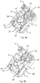
Figure 5a shows an exploded view of a latching hinge with the distance element in a first position according to an embodiment of the invention. -
Figure 5b shows an exploded view of a latching hinge with the distance element in a second position according to an embodiment of the invention. -
Figure 6 shows a perspective view of a support plate according to an embodiment of the invention. -
Figure 7 shows a cross-section of a body and support plate of a latching hinge according to an embodiment of the invention. -
Figures 8a and 8b show a cross-section of a latching hinge according to an embodiment of the invention. - The present invention will be described more fully hereinafter with reference to the accompanying drawings. In the drawings, like numbers refer to like elements.
- The latching
hinge 1 according to the invention is illustrated infig. 1 . The latching hinge is shown in latched position with thehandle 2 rotated into contact with thebody 3. A lockingelement 21 may be rotated to lock thehandle 2 in latched position. In latched position, the latchinghinge 1 has the function of a hinge, wherein thebody 3 and handle 2 are rotatable relative to thehinge part 4. - In
fig. 2 , the latchinghinge 1 is show in unlatched position with thehandle 2 rotated away from thebody 3, allowing thebody 3 to be released from thehinge part 4. In the unlatched position of thehandle 2, the latchinghinge 1 is openable as a latch for the door to a door frame. -
Fig. 3 shows a door facing side of the latchinghinge 1. Asupport plate 6 is attached to thebody 3 throughholes 61 via fastening means such as screws. Thebody 3 andsupport plate 6 are configured to abut a door. Thehinge 4 is configured to be arranged to a door frame. - An example of a body facing side of a
distance element 5 according to the invention is shown infig 4a . Thedistance element 5 is arranged between thebody 3 and thesupport plate 6. Thedistance element 5 comprises at least onehole 51 for fastening thedistance element 5 to thesupport plate 6 and thebody 3. Fastening may be done by for example use of a screw or other fastening means. - The thickness t varies across the
distance element 5, with a first portion p1 having a thickness t1 which may be less than a thickness t2 of a second portion p2. The thickness t2 is further smaller than a thickness t3 of a third portion p3 of thedistance element 5. - The
distance element 5 further comprises a settingscrew head 52 for moving thedistance element 5 between different positions of the distance element. The settingscrew head 52 may be a socket head cap screw, a screw head, a nut, or other means for rotation. The settingscrew head 52 protrudes through thebody 3 such that thedistance element 5 can be moved or rotated without exposing the body facing side of thedistance element 5, as illustrated infig 2 . The distance may be elected usingmarks 33 on the body, indicating the position or thickness of the current position of the distance element, also indicated infigure 2 . - The different thicknesses t1, t2, t3 set the distance between the
support plate 6 and thebody 3. Thedistance element 5 may be moved between the positions by rotation or by a linear motion. The distance element is in the illustrated embodiment moved by rotation around the settingscrew head 52. The position of the distance element may alternatively be shifted by for example linear vertical or horizontal movement of the distance element. - The
distance element 5 may further be of a circular or circle sectional shape or of any other shape, such as a rectangular shape comprising different thicknesses in different portions of the element. - In
fig. 4b the support plate facing side of thedistance element 5 is shown. Thedistance element 5 comprises portions p1, p2, p3 of different thicknesses t1, t2, t3, and is moveable between different positions when arranged in the latchinghinge 1. Between each portion p1, p2, p3 and an adjacent portion p1, p2, p3 there is aside edge 50, 50'. The side edges 50, 50' provide the change of thickness between the portions p1, p2, p3. The side edges 50, 50' are inclined towards the connecting portions p1, p2, p3. Thedistance element 5 further comprises aprotrusion 53. The protrudingsurface 53 is at least partly circularly shaped, and has a curvature CD facing the portions p1, p2, p3. Theprotrusion 53 extends to have a thickness larger than the thickness t3 of the third portion p3. -
Fig. 5a shows thedistance element 5 in a first position where the first portion p1 with thickness t1 is fixed byscrews 32 via theholes 51 to thebody 1 and sets the distance between thebody 1 and the support plate 6 (not shown).Fig 5a further illustrates the protrudingparts 31, which may serve as to maximize the contact area between thesupport plate 6 and thebody 3. Thesupport plate 6 and thebody 3 may be fixed to each other byscrews 32. The means 32 fastening thebody 3 and thesupport plate 6 to each other may extend through a protrudingpart 31. - The protruding
part 31 has a longitudinal extension and is positioned either on thesupport plate 6 or as illustrated on thebody 3. The protrudingpart 31 has a circle segment profile to maximize the contact area as thesupport plate 6 andbody 3 are rotated away from each other. Thedistance element 5 is positioned in acavity 34 of thebody 3 such that when thedistance element 5 is positioned in a position with the thinnest portion p1 in contact with thesupport plate 6, thesupport plate 6 is in contact with thebody 3 at the area next of the distance element. In such situation, thedistance element 5 has no effect on the positioning of thesupport plate 6 relative to thebody 3. -
Fig 5b shows thedistance element 5 in a third position where the third portion p3 sets the distance between thebody 3 and thesupport plate 6 to a different distance than that of p1, illustrated infig. 5a . Thedistance element 5 is fixed in said third position byscrew 32 via theholes 51 to thebody 1. In the same manner, in a second position, not shown, a second portion p2 having a thickness t2 sets the distance between thebody 1 and thesupport plate 6. - The
support plate 6 is illustrated infig. 6 . Thesupport plate 6 comprises a contactingpart 62 which abuts thedistance element 5 as to create an area of contact there between regardless the current position of thedistance element 5. Thecontact part 62 is in contact with the portion p1, p2, p3 that currently is in a distance setting position (as p1 infig. 5a ). The portions p1, p2, p3 of thedistance element 5 are divided as segments of thedistance element 5. At least one of thesides 50, 50' of each portion p1, p2, p3 extends in a corresponding angle as thesides 60, 60' of the contactingpart 62. Thesides 50,50' of thedistance element 5 and theangle corresponding sides 60, 60' of the contactingpart 62 aid in holding thedistance element 5 in a fixed position relative thesupport plate 6 in certain of the distance element's 5 positions p1, p2, p3 when the sides of the different parts are in contact with each other. - The
distance element 5 has a protrusion 53 (seefig. 4b ) extending above the portions p1, p2, p3 and facing thesupport plate 6. Theprotrusion 53 has a curvature CD corresponding to the curvature CS of the contacting part such that the side of theprotrusion 53 of the distance element and theside 63 of the contacting part provide an area of contact between the support plate and thedistance element 5. This area of contact aids in guiding thedistance element 5 in the correct position with respect to thesupport element 6 during rotation of thedistance element 5. - Further, the
support plate 6 comprisesholes 61screws 32 to attach to thebody 3 and a hole 61' for fixation to thebody 3 via thedistance element 5. Thesupport plate 6 comprises afirst area 6a and asecond area 6b. Thefirst area 6a may be in contact with thebody 3 for a certain thickness of thedistance element 5 and tilted away from thebody 3 when the thickness t of thedistance element 5 increases. Thesecond area 6b of thesupport plate 6 is always in contact with thebody 3. - A cross-section of the latching
hinge 1 is illustrated infig. 7 . Thebody 3 comprises a protrudingsurface 31 such as to create a contact surface to thesupport plate 6 when thesupport plate 6 is distanced from thebody 3 by the distance element 5 (seefig. 8b ). The protrudingsurface 31 has a cross-sectional form of a circle segment extending above the surrounding surface of thebody 3. When thesupport plate 6 is distanced from thebody 3 at the location of thedistance element 5, thesupport plate 6 will be rotated around a point on the protrudingsurface 31. A connection between thebody 3 and thesupport plate 5 can thereby be withheld at the same place, i.e. by means of fastening means extending through the protrudingsurface 31. - In
figure 8a a cross-section of thebody 3, thesupport plate 6, and thedistance element 5 of the latchinghinge 1 are shown. Thedistance element 5 is shown with a portion p1 of thickness t1 setting the distance between thesupport plate 6 and thebody 3. In a certain position alower surface 6c of thesupport plate 6 lies in a plane A suspended by a door facing side of thebody 3. Using themeans 52 for moving thedistance element 5 to a position p2, p3 with a thickness t2, t3 thicker than t1, will cause thefirst area 6a of the support plate to tilt away from thebody 3 through the plane A, as illustrated infig. 8b , such that thelower surface 6c of thesupport plate 6 is offset in relation to plane A. - The latching
hinge 1 may be produced from plastics, metal, a combination of these of other suitable material and may be produced in separate parts for example by injection molding. - In the drawings and specification, there have been disclosed preferred embodiments and examples of the invention and, although specific terms are employed, they are used in a generic and descriptive sense only and not for the purpose of limitation, the scope of the invention being set forth in the following claims.
Claims (15)
- A latching hinge (1) for arrangement to a door and a door frame, the latching hinge comprising
a body (3) configured to be arranged to a door,
a hinge part (4) configured to be arranged on a door frame, wherein the body is rotatably arranged to the hinge part,
a handle (2) rotatably arranged to the body such that the body is released from the hinge part when the handle is in an unlatched position, and
a support plate (6) arranged at a door facing side of the body and configured to abut the door when the latching hinge is arranged thereto,
characterized in that
the latching hinge (1) further comprises a distance element (5) arranged in-between the support plate (6) and the body (3) and is moveable between at least a first position and a second position,
wherein the distance element in the second position provides an increased offset between the body and the support plate than in the first position. - A latching hinge (1) according to claim 1, wherein the distance element (5) is configured to offset the support plate (6) and the body by setting a distance between the support plate and the body.
- A latching hinge (1) according to claim 1 or 2, wherein the distance element (5) comprises at least a first and a second portion (p) having different thickness (t),
wherein the thickness (t1) of the first portion (p1) sets the distance between the support plate (6) and the body (3) when the distance element is in the first position, and the thickness (t2) of the second portion (p2) sets said distance when the distance element is in the second position. - A latching hinge (1) according to any of the previous claims, wherein said distance element (5) further comprises a means for moving (52) the distance element between the at least first and second positions.
- A latching hinge (1) according to any of the previous claims, wherein the distance element (5) is movable by rotation.
- A latching hinge (1) according to claim 4, wherein the distance element (5) is rotatable around the means for moving (52).
- A latching hinge (1) according to any of the previous claims, wherein the distance element (5) can be fixed by fastening means (32) to the body and the support plate (6) in any of the at least first or second position.
- A latching hinge (1) according to claim 5, wherein the fastening means (32) fixating the distance element (5) into a first or second position comprises a screw.
- A latching hinge (1) according to claim 3, wherein the support plate (6) comprises a contacting part (62) configured to protrude from the support plate and to abut the distance element (5) at any of the at least first and second portions (p).
- A latching hinge (1) according to any of the preceding claims, wherein said support plate (6) comprises a first area (6a) and a second area (6b) and wherein the distance element (5) is arranged in-between the body (3) and the support plate at the first area of the support plate, wherein the second area of the support plate is in contact with the body.
- A latching hinge (1) according to claim 10, wherein a protruding surface (31) configured to maximize the contact region between the body (3) and the second area (6b) of the support plate (6) is arranged on the body or on the support plate.
- A latching hinge (1) according to claim 11, wherein the protruding surface (31) has a cross-sectional form of a circle segment extending above the surface of the body (3) or the support plate (6).
- A latching hinge (1) according to any of the preceding claims, wherein the body (3) and the support plate (6) are configured to be fastened by use of fastening means (32) to each other and/or a door.
- A latching hinge (1) according to claims 12 and 13, wherein at least one fastening means (32) is intended to extend through the protruding surface (31).
- A latching hinge (1) according to any of the previous claims, wherein a door facing side of the body (3) comprises a plane (A) and wherein the support plate (6) comprises a lower surface (6c) placed in the plane in at least one of the positions of the distance element (5) and wherein the lower surface of the support plate is offset from said plane in at least one other position of the distance element.
Priority Applications (7)
| Application Number | Priority Date | Filing Date | Title |
|---|---|---|---|
| EP16188882.1A EP3296491B1 (en) | 2016-09-15 | 2016-09-15 | Adjustable latching hinge |
| PL16188882T PL3296491T3 (en) | 2016-09-15 | 2016-09-15 | Adjustable latching hinge |
| CN201780055659.9A CN109690003B (en) | 2016-09-15 | 2017-09-14 | Adjustable fitting for a door |
| CA3036214A CA3036214A1 (en) | 2016-09-15 | 2017-09-14 | Adjustable fitting for a door |
| PCT/EP2017/073085 WO2018050727A1 (en) | 2016-09-15 | 2017-09-14 | Adjustable fitting for a door |
| BR112019004439-6A BR112019004439B1 (en) | 2016-09-15 | 2017-09-14 | FITTING AND HINGE |
| US16/331,725 US10982474B2 (en) | 2016-09-15 | 2017-09-14 | Adjustable fitting for a door |
Applications Claiming Priority (1)
| Application Number | Priority Date | Filing Date | Title |
|---|---|---|---|
| EP16188882.1A EP3296491B1 (en) | 2016-09-15 | 2016-09-15 | Adjustable latching hinge |
Publications (2)
| Publication Number | Publication Date |
|---|---|
| EP3296491A1 EP3296491A1 (en) | 2018-03-21 |
| EP3296491B1 true EP3296491B1 (en) | 2021-02-24 |
Family
ID=56936333
Family Applications (1)
| Application Number | Title | Priority Date | Filing Date |
|---|---|---|---|
| EP16188882.1A Active EP3296491B1 (en) | 2016-09-15 | 2016-09-15 | Adjustable latching hinge |
Country Status (7)
| Country | Link |
|---|---|
| US (1) | US10982474B2 (en) |
| EP (1) | EP3296491B1 (en) |
| CN (1) | CN109690003B (en) |
| BR (1) | BR112019004439B1 (en) |
| CA (1) | CA3036214A1 (en) |
| PL (1) | PL3296491T3 (en) |
| WO (1) | WO2018050727A1 (en) |
Families Citing this family (3)
| Publication number | Priority date | Publication date | Assignee | Title |
|---|---|---|---|---|
| EP3296491B1 (en) * | 2016-09-15 | 2021-02-24 | Industrilås i Nässjö Aktiebolag | Adjustable latching hinge |
| WO2018081230A1 (en) * | 2016-10-25 | 2018-05-03 | Y-Knot, Llc | Devices and methods for securing knots |
| DE202019000349U1 (en) | 2019-01-24 | 2019-02-12 | Yury Kaganov | The easily removable hinge |
Family Cites Families (20)
| Publication number | Priority date | Publication date | Assignee | Title |
|---|---|---|---|---|
| DE3729531A1 (en) * | 1987-09-04 | 1989-03-16 | Lautenschlaeger Kg Karl | SNAP HINGE FOR CORNER CABINETS |
| US5283929A (en) * | 1992-06-01 | 1994-02-08 | Lin Tsong Chi | Hinge |
| AT405432B (en) * | 1994-11-17 | 1999-08-25 | Blum Gmbh Julius | FRAME HINGE |
| DE29511756U1 (en) * | 1995-07-20 | 1995-09-28 | Ferco Int Usine Ferrures | Wing-side corner bearing fitting for tilt and turn windows |
| US5555605A (en) * | 1995-10-16 | 1996-09-17 | Mosher; Gary M. | Door hinge alignment apparatus |
| AT6963U1 (en) * | 2003-02-21 | 2004-06-25 | Blum Gmbh Julius | HINGE |
| AT6962U1 (en) * | 2003-02-21 | 2004-06-25 | Blum Gmbh Julius | HINGE |
| DE202005007087U1 (en) * | 2005-05-03 | 2006-09-14 | Liebherr-Hausgeräte Lienz Gmbh | Fridge and / or freezer |
| WO2006136939A2 (en) * | 2005-06-24 | 2006-12-28 | Aroplast S.R.L. | Disassemblable hinge and cabinet using it |
| DE102006034306A1 (en) * | 2006-07-21 | 2008-01-24 | Liberty Hardware Mfg. Corp. | hinge |
| EP2157265B1 (en) * | 2008-08-21 | 2012-06-27 | VKR Holding A/S | Window hinge assembly and method of mounting a sash in a frame |
| CN101956499B (en) * | 2009-07-15 | 2013-05-22 | 赵芬 | Adjustable hinge mechanism and adjusting method |
| CN102292511A (en) * | 2009-11-25 | 2011-12-21 | 东祐精密株式会社 | Hinge apparatus for a door |
| DE202011101342U1 (en) * | 2011-05-25 | 2012-08-27 | Prämeta GmbH & Co. KG | hinge |
| EP2923019B1 (en) * | 2012-11-26 | 2017-08-02 | Industrilås I Nässjö AB | Disassemblable hinge with a safety catch |
| CN106460424B (en) * | 2014-04-24 | 2018-06-01 | 阿普赛特技术有限公司 | For current-controlled door system |
| US9565941B2 (en) * | 2014-05-21 | 2017-02-14 | Grass America, Inc. | Hinge locking member |
| DE202015001918U1 (en) * | 2015-03-12 | 2016-06-14 | Dirak Dieter Ramsauer Konstruktionselemente Gmbh | Hinge for detachable metal doors |
| DE102015117505B3 (en) * | 2015-10-15 | 2017-02-02 | Emka Beschlagteile Gmbh & Co. Kg | hinge closure |
| EP3296491B1 (en) * | 2016-09-15 | 2021-02-24 | Industrilås i Nässjö Aktiebolag | Adjustable latching hinge |
-
2016
- 2016-09-15 EP EP16188882.1A patent/EP3296491B1/en active Active
- 2016-09-15 PL PL16188882T patent/PL3296491T3/en unknown
-
2017
- 2017-09-14 WO PCT/EP2017/073085 patent/WO2018050727A1/en active Application Filing
- 2017-09-14 CA CA3036214A patent/CA3036214A1/en not_active Abandoned
- 2017-09-14 BR BR112019004439-6A patent/BR112019004439B1/en active IP Right Grant
- 2017-09-14 US US16/331,725 patent/US10982474B2/en active Active
- 2017-09-14 CN CN201780055659.9A patent/CN109690003B/en active Active
Non-Patent Citations (1)
| Title |
|---|
| None * |
Also Published As
| Publication number | Publication date |
|---|---|
| US20190203510A1 (en) | 2019-07-04 |
| CN109690003A (en) | 2019-04-26 |
| CN109690003B (en) | 2021-07-27 |
| BR112019004439B1 (en) | 2023-05-02 |
| EP3296491A1 (en) | 2018-03-21 |
| CA3036214A1 (en) | 2018-03-22 |
| BR112019004439A2 (en) | 2019-05-28 |
| PL3296491T3 (en) | 2021-08-16 |
| US10982474B2 (en) | 2021-04-20 |
| WO2018050727A1 (en) | 2018-03-22 |
Similar Documents
| Publication | Publication Date | Title |
|---|---|---|
| EP3296491B1 (en) | Adjustable latching hinge | |
| US20170152689A1 (en) | Adjustable door hinge | |
| KR20130131284A (en) | A hooking device for hooking a drawer to a longitudinal guide | |
| RU2006130420A (en) | LOCK FOR INSTALLATION IN THIN WALL HOLES | |
| CN1761798B (en) | Gemel | |
| EP2166186B1 (en) | An adjustable door or window hinge | |
| KR20070008575A (en) | Hinge for mounting in an opening | |
| US7971319B2 (en) | Hinge for doors or windows | |
| US20080209677A1 (en) | Furniture hinge | |
| KR101968628B1 (en) | Pivot hinge apparatus | |
| CN111094681A (en) | Rotary fitting for a covered device on a window or door | |
| EP2607588B1 (en) | Hinge for a roof window with pivoting or double action sash | |
| EP2927407B1 (en) | Hinge | |
| KR102105870B1 (en) | Door hinge device for improving efficiency of door closing | |
| US6877782B2 (en) | Adjustable sliding bolt for a lock | |
| KR200414430Y1 (en) | Height adjustable hinges | |
| KR101758890B1 (en) | Lower Roller Supporting Structure for Sliding Door | |
| JP2889496B2 (en) | Hinge | |
| KR102105871B1 (en) | Door hinge device for setting elevating limit of bracket body | |
| JP2020070716A (en) | Window stay | |
| JP2006265984A (en) | Receiving seat of sickle lock | |
| CN104736785B (en) | Sliding door closing system of a piece of furniture | |
| KR20160092355A (en) | Hinge for door | |
| NL2012870B1 (en) | Curtain rail support. | |
| JP2006053355A (en) | Document pressing plate opening/closing device |
Legal Events
| Date | Code | Title | Description |
|---|---|---|---|
| PUAI | Public reference made under article 153(3) epc to a published international application that has entered the european phase |
Free format text: ORIGINAL CODE: 0009012 |
|
| STAA | Information on the status of an ep patent application or granted ep patent |
Free format text: STATUS: THE APPLICATION HAS BEEN PUBLISHED |
|
| AK | Designated contracting states |
Kind code of ref document: A1 Designated state(s): AL AT BE BG CH CY CZ DE DK EE ES FI FR GB GR HR HU IE IS IT LI LT LU LV MC MK MT NL NO PL PT RO RS SE SI SK SM TR |
|
| AX | Request for extension of the european patent |
Extension state: BA ME |
|
| STAA | Information on the status of an ep patent application or granted ep patent |
Free format text: STATUS: REQUEST FOR EXAMINATION WAS MADE |
|
| 17P | Request for examination filed |
Effective date: 20180607 |
|
| RBV | Designated contracting states (corrected) |
Designated state(s): AL AT BE BG CH CY CZ DE DK EE ES FI FR GB GR HR HU IE IS IT LI LT LU LV MC MK MT NL NO PL PT RO RS SE SI SK SM TR |
|
| GRAP | Despatch of communication of intention to grant a patent |
Free format text: ORIGINAL CODE: EPIDOSNIGR1 |
|
| STAA | Information on the status of an ep patent application or granted ep patent |
Free format text: STATUS: GRANT OF PATENT IS INTENDED |
|
| INTG | Intention to grant announced |
Effective date: 20200921 |
|
| GRAS | Grant fee paid |
Free format text: ORIGINAL CODE: EPIDOSNIGR3 |
|
| GRAA | (expected) grant |
Free format text: ORIGINAL CODE: 0009210 |
|
| STAA | Information on the status of an ep patent application or granted ep patent |
Free format text: STATUS: THE PATENT HAS BEEN GRANTED |
|
| AK | Designated contracting states |
Kind code of ref document: B1 Designated state(s): AL AT BE BG CH CY CZ DE DK EE ES FI FR GB GR HR HU IE IS IT LI LT LU LV MC MK MT NL NO PL PT RO RS SE SI SK SM TR |
|
| RAP1 | Party data changed (applicant data changed or rights of an application transferred) |
Owner name: INDUSTRILAS I NAESSJOE AKTIEBOLAG |
|
| REG | Reference to a national code |
Ref country code: CH Ref legal event code: EP |
|
| REG | Reference to a national code |
Ref country code: AT Ref legal event code: REF Ref document number: 1364630 Country of ref document: AT Kind code of ref document: T Effective date: 20210315 |
|
| REG | Reference to a national code |
Ref country code: IE Ref legal event code: FG4D |
|
| REG | Reference to a national code |
Ref country code: DE Ref legal event code: R096 Ref document number: 602016053003 Country of ref document: DE |
|
| REG | Reference to a national code |
Ref country code: SE Ref legal event code: TRGR |
|
| REG | Reference to a national code |
Ref country code: LT Ref legal event code: MG9D |
|
| REG | Reference to a national code |
Ref country code: NL Ref legal event code: MP Effective date: 20210224 |
|
| PG25 | Lapsed in a contracting state [announced via postgrant information from national office to epo] |
Ref country code: LT Free format text: LAPSE BECAUSE OF FAILURE TO SUBMIT A TRANSLATION OF THE DESCRIPTION OR TO PAY THE FEE WITHIN THE PRESCRIBED TIME-LIMIT Effective date: 20210224 Ref country code: FI Free format text: LAPSE BECAUSE OF FAILURE TO SUBMIT A TRANSLATION OF THE DESCRIPTION OR TO PAY THE FEE WITHIN THE PRESCRIBED TIME-LIMIT Effective date: 20210224 Ref country code: HR Free format text: LAPSE BECAUSE OF FAILURE TO SUBMIT A TRANSLATION OF THE DESCRIPTION OR TO PAY THE FEE WITHIN THE PRESCRIBED TIME-LIMIT Effective date: 20210224 Ref country code: GR Free format text: LAPSE BECAUSE OF FAILURE TO SUBMIT A TRANSLATION OF THE DESCRIPTION OR TO PAY THE FEE WITHIN THE PRESCRIBED TIME-LIMIT Effective date: 20210525 Ref country code: BG Free format text: LAPSE BECAUSE OF FAILURE TO SUBMIT A TRANSLATION OF THE DESCRIPTION OR TO PAY THE FEE WITHIN THE PRESCRIBED TIME-LIMIT Effective date: 20210524 Ref country code: PT Free format text: LAPSE BECAUSE OF FAILURE TO SUBMIT A TRANSLATION OF THE DESCRIPTION OR TO PAY THE FEE WITHIN THE PRESCRIBED TIME-LIMIT Effective date: 20210624 Ref country code: NO Free format text: LAPSE BECAUSE OF FAILURE TO SUBMIT A TRANSLATION OF THE DESCRIPTION OR TO PAY THE FEE WITHIN THE PRESCRIBED TIME-LIMIT Effective date: 20210524 |
|
| REG | Reference to a national code |
Ref country code: AT Ref legal event code: MK05 Ref document number: 1364630 Country of ref document: AT Kind code of ref document: T Effective date: 20210224 |
|
| PG25 | Lapsed in a contracting state [announced via postgrant information from national office to epo] |
Ref country code: LV Free format text: LAPSE BECAUSE OF FAILURE TO SUBMIT A TRANSLATION OF THE DESCRIPTION OR TO PAY THE FEE WITHIN THE PRESCRIBED TIME-LIMIT Effective date: 20210224 Ref country code: RS Free format text: LAPSE BECAUSE OF FAILURE TO SUBMIT A TRANSLATION OF THE DESCRIPTION OR TO PAY THE FEE WITHIN THE PRESCRIBED TIME-LIMIT Effective date: 20210224 Ref country code: NL Free format text: LAPSE BECAUSE OF FAILURE TO SUBMIT A TRANSLATION OF THE DESCRIPTION OR TO PAY THE FEE WITHIN THE PRESCRIBED TIME-LIMIT Effective date: 20210224 |
|
| PG25 | Lapsed in a contracting state [announced via postgrant information from national office to epo] |
Ref country code: IS Free format text: LAPSE BECAUSE OF FAILURE TO SUBMIT A TRANSLATION OF THE DESCRIPTION OR TO PAY THE FEE WITHIN THE PRESCRIBED TIME-LIMIT Effective date: 20210624 |
|
| PG25 | Lapsed in a contracting state [announced via postgrant information from national office to epo] |
Ref country code: CZ Free format text: LAPSE BECAUSE OF FAILURE TO SUBMIT A TRANSLATION OF THE DESCRIPTION OR TO PAY THE FEE WITHIN THE PRESCRIBED TIME-LIMIT Effective date: 20210224 Ref country code: EE Free format text: LAPSE BECAUSE OF FAILURE TO SUBMIT A TRANSLATION OF THE DESCRIPTION OR TO PAY THE FEE WITHIN THE PRESCRIBED TIME-LIMIT Effective date: 20210224 Ref country code: AT Free format text: LAPSE BECAUSE OF FAILURE TO SUBMIT A TRANSLATION OF THE DESCRIPTION OR TO PAY THE FEE WITHIN THE PRESCRIBED TIME-LIMIT Effective date: 20210224 Ref country code: SM Free format text: LAPSE BECAUSE OF FAILURE TO SUBMIT A TRANSLATION OF THE DESCRIPTION OR TO PAY THE FEE WITHIN THE PRESCRIBED TIME-LIMIT Effective date: 20210224 |
|
| PGFP | Annual fee paid to national office [announced via postgrant information from national office to epo] |
Ref country code: FR Payment date: 20210818 Year of fee payment: 6 |
|
| REG | Reference to a national code |
Ref country code: DE Ref legal event code: R097 Ref document number: 602016053003 Country of ref document: DE |
|
| PG25 | Lapsed in a contracting state [announced via postgrant information from national office to epo] |
Ref country code: DK Free format text: LAPSE BECAUSE OF FAILURE TO SUBMIT A TRANSLATION OF THE DESCRIPTION OR TO PAY THE FEE WITHIN THE PRESCRIBED TIME-LIMIT Effective date: 20210224 Ref country code: SK Free format text: LAPSE BECAUSE OF FAILURE TO SUBMIT A TRANSLATION OF THE DESCRIPTION OR TO PAY THE FEE WITHIN THE PRESCRIBED TIME-LIMIT Effective date: 20210224 Ref country code: RO Free format text: LAPSE BECAUSE OF FAILURE TO SUBMIT A TRANSLATION OF THE DESCRIPTION OR TO PAY THE FEE WITHIN THE PRESCRIBED TIME-LIMIT Effective date: 20210224 |
|
| PGFP | Annual fee paid to national office [announced via postgrant information from national office to epo] |
Ref country code: GB Payment date: 20210819 Year of fee payment: 6 |
|
| PLBE | No opposition filed within time limit |
Free format text: ORIGINAL CODE: 0009261 |
|
| STAA | Information on the status of an ep patent application or granted ep patent |
Free format text: STATUS: NO OPPOSITION FILED WITHIN TIME LIMIT |
|
| PG25 | Lapsed in a contracting state [announced via postgrant information from national office to epo] |
Ref country code: ES Free format text: LAPSE BECAUSE OF FAILURE TO SUBMIT A TRANSLATION OF THE DESCRIPTION OR TO PAY THE FEE WITHIN THE PRESCRIBED TIME-LIMIT Effective date: 20210224 Ref country code: AL Free format text: LAPSE BECAUSE OF FAILURE TO SUBMIT A TRANSLATION OF THE DESCRIPTION OR TO PAY THE FEE WITHIN THE PRESCRIBED TIME-LIMIT Effective date: 20210224 |
|
| 26N | No opposition filed |
Effective date: 20211125 |
|
| PG25 | Lapsed in a contracting state [announced via postgrant information from national office to epo] |
Ref country code: SI Free format text: LAPSE BECAUSE OF FAILURE TO SUBMIT A TRANSLATION OF THE DESCRIPTION OR TO PAY THE FEE WITHIN THE PRESCRIBED TIME-LIMIT Effective date: 20210224 |
|
| PG25 | Lapsed in a contracting state [announced via postgrant information from national office to epo] |
Ref country code: IT Free format text: LAPSE BECAUSE OF FAILURE TO SUBMIT A TRANSLATION OF THE DESCRIPTION OR TO PAY THE FEE WITHIN THE PRESCRIBED TIME-LIMIT Effective date: 20210224 |
|
| REG | Reference to a national code |
Ref country code: CH Ref legal event code: PL |
|
| REG | Reference to a national code |
Ref country code: BE Ref legal event code: MM Effective date: 20210930 |
|
| PG25 | Lapsed in a contracting state [announced via postgrant information from national office to epo] |
Ref country code: IS Free format text: LAPSE BECAUSE OF FAILURE TO SUBMIT A TRANSLATION OF THE DESCRIPTION OR TO PAY THE FEE WITHIN THE PRESCRIBED TIME-LIMIT Effective date: 20210624 Ref country code: MC Free format text: LAPSE BECAUSE OF FAILURE TO SUBMIT A TRANSLATION OF THE DESCRIPTION OR TO PAY THE FEE WITHIN THE PRESCRIBED TIME-LIMIT Effective date: 20210224 |
|
| PG25 | Lapsed in a contracting state [announced via postgrant information from national office to epo] |
Ref country code: LU Free format text: LAPSE BECAUSE OF NON-PAYMENT OF DUE FEES Effective date: 20210915 Ref country code: IE Free format text: LAPSE BECAUSE OF NON-PAYMENT OF DUE FEES Effective date: 20210915 Ref country code: BE Free format text: LAPSE BECAUSE OF NON-PAYMENT OF DUE FEES Effective date: 20210930 |
|
| PG25 | Lapsed in a contracting state [announced via postgrant information from national office to epo] |
Ref country code: LI Free format text: LAPSE BECAUSE OF NON-PAYMENT OF DUE FEES Effective date: 20210930 Ref country code: CH Free format text: LAPSE BECAUSE OF NON-PAYMENT OF DUE FEES Effective date: 20210930 |
|
| GBPC | Gb: european patent ceased through non-payment of renewal fee |
Effective date: 20220915 |
|
| PG25 | Lapsed in a contracting state [announced via postgrant information from national office to epo] |
Ref country code: HU Free format text: LAPSE BECAUSE OF FAILURE TO SUBMIT A TRANSLATION OF THE DESCRIPTION OR TO PAY THE FEE WITHIN THE PRESCRIBED TIME-LIMIT; INVALID AB INITIO Effective date: 20160915 |
|
| PG25 | Lapsed in a contracting state [announced via postgrant information from national office to epo] |
Ref country code: CY Free format text: LAPSE BECAUSE OF FAILURE TO SUBMIT A TRANSLATION OF THE DESCRIPTION OR TO PAY THE FEE WITHIN THE PRESCRIBED TIME-LIMIT Effective date: 20210224 |
|
| PG25 | Lapsed in a contracting state [announced via postgrant information from national office to epo] |
Ref country code: FR Free format text: LAPSE BECAUSE OF NON-PAYMENT OF DUE FEES Effective date: 20220930 |
|
| PG25 | Lapsed in a contracting state [announced via postgrant information from national office to epo] |
Ref country code: GB Free format text: LAPSE BECAUSE OF NON-PAYMENT OF DUE FEES Effective date: 20220915 |
|
| PGFP | Annual fee paid to national office [announced via postgrant information from national office to epo] |
Ref country code: TR Payment date: 20230905 Year of fee payment: 8 |
|
| PGFP | Annual fee paid to national office [announced via postgrant information from national office to epo] |
Ref country code: SE Payment date: 20230816 Year of fee payment: 8 Ref country code: PL Payment date: 20230915 Year of fee payment: 8 Ref country code: DE Payment date: 20230818 Year of fee payment: 8 |