EP3296409A1 - Method for producing steel material, apparatus for cooling steel material, and steel material - Google Patents
Method for producing steel material, apparatus for cooling steel material, and steel material Download PDFInfo
- Publication number
- EP3296409A1 EP3296409A1 EP16792616.1A EP16792616A EP3296409A1 EP 3296409 A1 EP3296409 A1 EP 3296409A1 EP 16792616 A EP16792616 A EP 16792616A EP 3296409 A1 EP3296409 A1 EP 3296409A1
- Authority
- EP
- European Patent Office
- Prior art keywords
- cooling
- steel material
- rail
- longitudinal direction
- conveyance
- Prior art date
- Legal status (The legal status is an assumption and is not a legal conclusion. Google has not performed a legal analysis and makes no representation as to the accuracy of the status listed.)
- Granted
Links
Images



Classifications
-
- C—CHEMISTRY; METALLURGY
- C21—METALLURGY OF IRON
- C21D—MODIFYING THE PHYSICAL STRUCTURE OF FERROUS METALS; GENERAL DEVICES FOR HEAT TREATMENT OF FERROUS OR NON-FERROUS METALS OR ALLOYS; MAKING METAL MALLEABLE, e.g. BY DECARBURISATION OR TEMPERING
- C21D9/00—Heat treatment, e.g. annealing, hardening, quenching or tempering, adapted for particular articles; Furnaces therefor
- C21D9/04—Heat treatment, e.g. annealing, hardening, quenching or tempering, adapted for particular articles; Furnaces therefor for rails
-
- B—PERFORMING OPERATIONS; TRANSPORTING
- B21—MECHANICAL METAL-WORKING WITHOUT ESSENTIALLY REMOVING MATERIAL; PUNCHING METAL
- B21B—ROLLING OF METAL
- B21B1/00—Metal-rolling methods or mills for making semi-finished products of solid or profiled cross-section; Sequence of operations in milling trains; Layout of rolling-mill plant, e.g. grouping of stands; Succession of passes or of sectional pass alternations
- B21B1/08—Metal-rolling methods or mills for making semi-finished products of solid or profiled cross-section; Sequence of operations in milling trains; Layout of rolling-mill plant, e.g. grouping of stands; Succession of passes or of sectional pass alternations for rolling structural sections, i.e. work of special cross-section, e.g. angle steel
- B21B1/085—Rail sections
-
- B—PERFORMING OPERATIONS; TRANSPORTING
- B21—MECHANICAL METAL-WORKING WITHOUT ESSENTIALLY REMOVING MATERIAL; PUNCHING METAL
- B21B—ROLLING OF METAL
- B21B45/00—Devices for surface or other treatment of work, specially combined with or arranged in, or specially adapted for use in connection with, metal-rolling mills
- B21B45/02—Devices for surface or other treatment of work, specially combined with or arranged in, or specially adapted for use in connection with, metal-rolling mills for lubricating, cooling, or cleaning
- B21B45/0203—Cooling
-
- C—CHEMISTRY; METALLURGY
- C21—METALLURGY OF IRON
- C21D—MODIFYING THE PHYSICAL STRUCTURE OF FERROUS METALS; GENERAL DEVICES FOR HEAT TREATMENT OF FERROUS OR NON-FERROUS METALS OR ALLOYS; MAKING METAL MALLEABLE, e.g. BY DECARBURISATION OR TEMPERING
- C21D1/00—General methods or devices for heat treatment, e.g. annealing, hardening, quenching or tempering
-
- C—CHEMISTRY; METALLURGY
- C22—METALLURGY; FERROUS OR NON-FERROUS ALLOYS; TREATMENT OF ALLOYS OR NON-FERROUS METALS
- C22C—ALLOYS
- C22C38/00—Ferrous alloys, e.g. steel alloys
- C22C38/002—Ferrous alloys, e.g. steel alloys containing In, Mg, or other elements not provided for in one single group C22C38/001 - C22C38/60
-
- C—CHEMISTRY; METALLURGY
- C22—METALLURGY; FERROUS OR NON-FERROUS ALLOYS; TREATMENT OF ALLOYS OR NON-FERROUS METALS
- C22C—ALLOYS
- C22C38/00—Ferrous alloys, e.g. steel alloys
- C22C38/02—Ferrous alloys, e.g. steel alloys containing silicon
-
- C—CHEMISTRY; METALLURGY
- C22—METALLURGY; FERROUS OR NON-FERROUS ALLOYS; TREATMENT OF ALLOYS OR NON-FERROUS METALS
- C22C—ALLOYS
- C22C38/00—Ferrous alloys, e.g. steel alloys
- C22C38/04—Ferrous alloys, e.g. steel alloys containing manganese
-
- C—CHEMISTRY; METALLURGY
- C22—METALLURGY; FERROUS OR NON-FERROUS ALLOYS; TREATMENT OF ALLOYS OR NON-FERROUS METALS
- C22C—ALLOYS
- C22C38/00—Ferrous alloys, e.g. steel alloys
- C22C38/06—Ferrous alloys, e.g. steel alloys containing aluminium
-
- C—CHEMISTRY; METALLURGY
- C22—METALLURGY; FERROUS OR NON-FERROUS ALLOYS; TREATMENT OF ALLOYS OR NON-FERROUS METALS
- C22C—ALLOYS
- C22C38/00—Ferrous alloys, e.g. steel alloys
- C22C38/14—Ferrous alloys, e.g. steel alloys containing titanium or zirconium
-
- B—PERFORMING OPERATIONS; TRANSPORTING
- B21—MECHANICAL METAL-WORKING WITHOUT ESSENTIALLY REMOVING MATERIAL; PUNCHING METAL
- B21B—ROLLING OF METAL
- B21B45/00—Devices for surface or other treatment of work, specially combined with or arranged in, or specially adapted for use in connection with, metal-rolling mills
- B21B45/02—Devices for surface or other treatment of work, specially combined with or arranged in, or specially adapted for use in connection with, metal-rolling mills for lubricating, cooling, or cleaning
- B21B45/0203—Cooling
- B21B45/0209—Cooling devices, e.g. using gaseous coolants
- B21B2045/0212—Cooling devices, e.g. using gaseous coolants using gaseous coolants
-
- B—PERFORMING OPERATIONS; TRANSPORTING
- B21—MECHANICAL METAL-WORKING WITHOUT ESSENTIALLY REMOVING MATERIAL; PUNCHING METAL
- B21B—ROLLING OF METAL
- B21B45/00—Devices for surface or other treatment of work, specially combined with or arranged in, or specially adapted for use in connection with, metal-rolling mills
- B21B45/02—Devices for surface or other treatment of work, specially combined with or arranged in, or specially adapted for use in connection with, metal-rolling mills for lubricating, cooling, or cleaning
- B21B45/0203—Cooling
- B21B45/0209—Cooling devices, e.g. using gaseous coolants
- B21B45/0215—Cooling devices, e.g. using gaseous coolants using liquid coolants, e.g. for sections, for tubes
- B21B2045/0221—Cooling devices, e.g. using gaseous coolants using liquid coolants, e.g. for sections, for tubes for structural sections, e.g. H-beams
-
- C—CHEMISTRY; METALLURGY
- C22—METALLURGY; FERROUS OR NON-FERROUS ALLOYS; TREATMENT OF ALLOYS OR NON-FERROUS METALS
- C22C—ALLOYS
- C22C38/00—Ferrous alloys, e.g. steel alloys
-
- C—CHEMISTRY; METALLURGY
- C22—METALLURGY; FERROUS OR NON-FERROUS ALLOYS; TREATMENT OF ALLOYS OR NON-FERROUS METALS
- C22C—ALLOYS
- C22C38/00—Ferrous alloys, e.g. steel alloys
- C22C38/60—Ferrous alloys, e.g. steel alloys containing lead, selenium, tellurium, or antimony, or more than 0.04% by weight of sulfur
Definitions
- the present disclosure relates to a method for producing a steel material, an apparatus for cooling a steel material, and a steel material.
- a rail for railways One of the longest steel materials is a rail for railways.
- a rail where a rail head section has a pearlite structure high in hardness is, for example, produced as follows.
- bloom cast by continuous casting is reheated to 1100°C or more, and thereafter hot rolled by rough rolling and finish rolling so as to have a predetermined rail shape.
- the rolling method in each rolling step is performed by a combination of caliber rolling and universal rolling, or by only caliber rolling, and such rough rolling is performed for a plurality of passes and such finish rolling is performed for a plurality of passes or a single pass.
- the rail here usually has a length of about 50 m to 200 m by hot rolling.
- thermoforming step an unsteady section at an end of the rail hot rolled is hot sawn (hot sawing step).
- a heat treatment apparatus is here limited with respect to the length, further sawing is performed so that a predetermined length (for example, 25 m) is achieved.
- a coolant air, water, mist, or the like
- a cooling apparatus thereby performing forced cooling (heat treatment step).
- the rail is restricted by a restraint apparatus such as a clamp, and the coolant is sprayed to a head section, a foot section, and also, if necessary, a web.
- the cooling apparatus usually performs cooling until the temperature of the head section of the rail reaches 650°C or less. After such forced cooling is completed, the rail is released from the restraint apparatus, and is further conveyed to a cooling bed and cooled to 100°C or less.
- the rail for railways is, for example, a rail for use in a severe environment where heavy goods such as coal and iron ore are transported from any mine of natural resources such as coal
- a rail is demanded to have high wear resistance and high toughness, and therefore the heat treatment step is required.
- the heat treatment is performed, thereby enabling the rail to be high in hardness and decreasing the amount of wear in use, and therefore the effects of increasing the rail replacement period and decreasing the life-time cost are achieved.
- a case where the variation in hardness is large in the longitudinal direction of the rail is not preferable because the amount of wear is larger at a low-hardness section than a high-hardness section, thereby not only increasing the vibration in train running, but also decreasing the replacement period.
- a heat treatment method which allows the rail to be small in the variation in hardness and high in hardness.
- PTL 1 discloses a method for suppressing a cooling rate to 7°C/sec or less, as a method for decreasing the variation in hardness of a rail.
- PTL 2 discloses a method for oscillating an H-shaped steel in an amount obtained by an Equation with the pitch between nozzles being adopted as a parameter in accelerated cooling of the H-shaped steel, as a method for uniformly cooling a steel material.
- PTL 3 discloses a method for oscillating a steel material at a distance 5 times to 10 times the distance in the longitudinal direction of the material of a guide roller, as a method for uniformly cooling a steel material.
- the method described in PTL 1 can decrease the influence of the variation in temperature at the start of a heat treatment in the longitudinal direction of a steel material on the variation in hardness.
- the variation in cooling rate is caused in the longitudinal direction of a steel material, uniform hardness is not achieved. Therefore, it is difficult to produce a steel material uniform in material properties in the longitudinal direction.
- the present invention has been then made in consideration of the above problems, and an object thereof is to provide a method for producing a steel material uniform in material properties in the longitudinal direction, an apparatus for cooling a steel material, and a steel material.
- One aspect of the present invention provides a method for producing a steel material, wherein, when a cooling apparatus having a plurality of cooling sections disposed side by side in the longitudinal direction of a steel material cools the steel material hot worked or cooled/reheated, the steel material is conveyed at a conveyance distance L o (m) satisfying Equation (1), in one direction along with the longitudinal direction of the steel material, in the cooling apparatus: m ⁇ 0.20 ⁇ L h ⁇ L o ⁇ m ⁇ 0.20 ⁇ L h
- One aspect of the present invention provides an apparatus for cooling a steel material hot worked or cooled/reheated, including: a plurality of cooling sections disposed side by side in the longitudinal direction of the steel material; and a conveyance section that conveys the steel material at a conveyance distance L o (m) satisfying Equation (1), in one direction along with the longitudinal direction of the steel material in the cooling apparatus, during cooling of the steel material in the cooling sections.
- One aspect of the present invention provides a steel material produced by hot working or cooling/reheating and thereafter cooling in a cooling apparatus having a plurality of cooling sections disposed side by side in a longitudinal direction, wherein, during cooling in the cooling apparatus, the steel material is produced with being conveyed at a conveyance distance L o (m) satisfying Equation (1), in one direction along with the longitudinal direction of the steel material in the cooling apparatus.
- One aspect of the present invention can provide a method for producing a steel material uniform in material properties in the longitudinal direction, an apparatus for cooling a steel material, and a steel material.
- a rail 1 is produced as a steel material in the present embodiment.
- the cooling apparatus 2 is used in a heat treatment step performed after a hot rolling step or a hot sawing step described below, and forcedly cools a rail 1 having a high temperature.
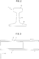
- the rail 1 when viewed cross-sectionally perpendicular to the longitudinal direction, includes a head section 11 and a foot section 13 which extend in the width direction and which are opposite to each other in the vertical direction, and a web section 12 which connects the head section 11 disposed above and the foot section 13 disposed below and which extends in the vertical direction, as illustrated in FIG. 2 .
- the cooling apparatus 2 includes head section-cooling headers 21a to 21c, a foot section-cooling header 22, a pair of clamps 23a and 23b, a thermometer 24 in the apparatus, and a conveyance section 25.
- the head section-cooling headers 21a to 21c, and the foot section-cooling header 22 serve as cooling sections for cooling the rail 1, and a plurality of the respective headers are provided continuously side by side in the y-axis direction serving as the longitudinal direction of the rail 1.
- the head section-cooling headers 21a to 21c, and the foot section-cooling header 22 are also collectively called cooling headers.
- the head section-cooling headers 21a to 21c have coolant-spraying outlets arranged at pitches of several mm to 100 mm, and the coolant-spraying outlets of each of the head section-cooling headers 21a to 21c are provided oppositely on each of the head top surface (end surface in the z-axis positive direction) and the head side surfaces (both end surfaces in the x-axis positive direction) of the head section 11.
- the head section-cooling headers 21a to 21c each spray a coolant supplied from a supply section not illustrated, to the head top surface and the head side surface of the head section 11, thereby subjecting the head section 11 to forced cooling.
- the coolant to be used is air, spray water, mist, or the like.
- Respective pressure measurement apparatuses 211a to 211c are also provided on coolant supply pathways of the head section-cooling headers 21a to 21c, and the coolant spray pressure is monitored.
- the foot section-cooling header 22 has coolant-spraying outlets arranged at pitches of several mm to 100 mm, and the coolant-spraying outlets are provided opposite to the lower surface (end surface in the z-axis negative direction) of the foot section 13.
- the foot section-cooling header 22 sprays a coolant supplied from a supply section not illustrated, to the lower surface of the foot section 13, thereby subjecting the foot section 13 to forced cooling, as in the head section-cooling headers 21a to 21c.
- the coolant to be used is air, spray water, mist, or the like, as in the head section-cooling headers 21a to 21c.
- a pressure apparatus 221 is also provided on a coolant supply pathway of the foot section-cooling header 22, and the coolant spray pressure is monitored.
- the head section-cooling headers 21a to 21c and the foot section-cooling header 22 each have the same length in the y-axis direction.
- the cooling headers are heated from the rail 1 and thus thermally deformed, thereby causing warpage (the generation mechanism of such warpage is described below) to be generated.
- the amount of warpage of the cooling headers, generated at the same curvature, increases with the square of the length of the cooling headers in the z-axis direction. Therefore, the length of the cooling headers in the z-axis direction is preferably shorter.
- an increase in the number of the cooling headers provided in the z-axis direction for a decrease in the length of the cooling headers is not preferable because there are required many feed ports of the coolant as well as many measurement devices and control devices of the amount of coolant spray (for example, a pressure gauge, a flow meter, and a flow regulator) which are mounted to the cooling headers and a pipe arrangement.
- the length of the cooling headers in the z-axis direction is needed to be a proper length, and is preferably 0.5 m or more and 4 m or less.
- the head section-cooling headers 21a to 21c and the foot section-cooling header 22 provided side by side in the y-axis direction are preferably provided as closer as possible so that any cooling irregularity is not caused.
- the pair of clamps 23a and 23b is an instrument for sandwiching each of both ends of the foot section 13 in the x-axis direction to thereby support and restrain the rail 1.
- the pair of clamps 23a and 23b is plurally provided over the entire length in the longitudinal direction of the rail 1 with being several meters apart.
- the thermometer 24 in the apparatus is a non-contact thermometer such as a radiation thermometer, and measures the surface temperature of at least one point on the head top surface of the head section 11.
- the conveyance section 25 is a conveyance mechanism connected to the pair of clamps 23a and 23b, and is an apparatus that conveys the pair of clamps 23a and 23b in the y-axis direction, thereby conveying the rail 1 in the cooling apparatus 2.
- the detail of a conveyance operation of the conveyance section 25 is described below.
- the amount of the coolant sprayed from each of the head section-cooling headers 21a to 21c and the foot section-cooling header 22 is adjusted by a control section not illustrated.
- the control section here acquires the temperature measurement result of the thermometer 24 in the apparatus, and the amount sprayed is adjusted, as needed, based on the temperature measurement result acquired.
- a carrying-in table 3 and a discharge table 4 are provided on the periphery of the cooling apparatus 2.
- the carrying-in table 3 is a table that conveys the rail 1 from a preceding step such as the hot rolling step to the cooling apparatus 2.
- the discharge table 4 is a table that conveys the rail 1 heat-treated in the cooling apparatus 2, to a next step such as a cooling bed or an examination instrument.
- An exit side thermometer 5 is a non-contact thermometer that measures the surface temperature of the head section 11 of the rail 1, as in the thermometer 24 in the apparatus, and that measures the temperature of the rail 1 discharged from the cooling apparatus 2 after the heat treatment.
- a perlite-based rail 1 is produced as a steel material.
- the rail 1 that can be used is, for example, steel including the following chemical component composition.
- Equation by "%" with respect to each chemical component means “% by mass", unless especially noted.
- C carbon
- the C content is thus preferably 0. 60% or more, more preferably 0.70% or more.
- C is excessively contained, an increase in the amount of the cementite can be achieved to result in increases in hardness and strength, but deterioration in ductility is conversely caused.
- an increase in the C content expands the temperature range of the ⁇ + ⁇ region, and promotes softening of a welded heat affected zone.
- the C content is preferably 1.05% or less, more preferably 0.97% or less.
- Si 0.1% or more and 1.5% or less
- Si silicon
- the Si content is preferably 0.1% or more, more preferably 0.2% or more.
- the Si content is preferably 1.5% or less, more preferably 1.3% or less.
- Mn 0.01% or more and 1.5% or less
- Mn manganese
- Mn has the effects of decreasing the temperature of perlite transformation and finning the perlite lamellar spacing, and therefore is an element effective for maintaining high hardness inside the rail 1. If the Mn content is less than 0.01%, however, the effects are less exerted. Therefore, the Mn content is preferably 0.01% or more, more preferably 0.3% or more. If the Mn content is more than 1.5%, the equilibrium transformation temperature (TE) of perlite is lowered, and martensitic transformation easily occurs in the structure. Therefore, the Mn content is preferably 1.5% or less, more preferably 1.3% or less.
- the P content is preferably made lower. Specifically, the P content is preferably 0.035% or less, more preferably 0.025% or less. If special refining or the like is here performed in order to decrease the P content as much as possible, cost rise is caused in smelting. Therefore, the P content is preferably 0.001% or more.
- the S content is preferably made lower. Specifically, the S content is preferably 0.030% or less, more preferably 0.015% or less. If the S content is here decreased as much as possible, cost rise in smelting is remarkably caused due to increases in smelting treatment time and the amount of a solvent. Therefore, the S content is preferably 0.0005% or more.
- Cr chromium
- TE equilibrium transformation temperature
- Cr when used in combination with Sb, is also effective for inhibiting a decarburization layer from being generated. Therefore, the Cr content is preferably 0.1% or more, more preferably 0.2% or more. If the Cr content is more than 2.0%, not only the possibility of the occurrence of welding defects is increased, but also hardenability is increased, and generation of martensite is promoted. Therefore, the Cr content is preferably 2.0% or less, more preferably 1.5% or less.
- the total content of Si and Cr is desirably 2.0% or less. The reason is because, if the total content of Si and Cr is more than 2.0%, an excessive increase in scale adhesiveness can inhibit scale peeling and promote decarburization.
- Sb antimony
- Sb has a remarkable effect of preventing decarburization during heating of a rail steel material in a heating furnace.
- Sb is added together with Cr, to thereby have the effect of reducing generation of a decarburization layer, when the Sb content is 0.005% or more. Therefore, the Sb content is preferably 0.005% or more, more preferably 0.01% or more. If the Sb content is more than 0.5%, the effect is saturated. Therefore, the Sb content is preferably 0.5% or less, more preferably 0.3% or less.
- the steel for use as the rail 1 may further contain, in addition to the chemical composition, one or more elements of Cu: 0.01% or more and 1.0% or less, Ni: 0.01% or more and 0.5% or less, Mo: 0.01% or more and 0.5% or less, V: 0.001% or more and 0.15% or less, and Nb: 0.001% or more and 0.030% or less.
- Cu copper is an element that can provide much higher hardness by solid solution strengthening. Cu also has the effect of suppressing decarburization. In order to expect such an effect, the Cu content is preferably 0.01% or more, more preferably 0.05% or more. If the Cu content is more than 1.0%, surface cracking due to embrittlement in continuous casting and/or rolling easily occurs. Therefore, the Cu content is preferably 1.0% or less, more preferably 0.6% or less.
- Ni 0.01% or more and 0.5% or less
- Ni nickel is an element effective for enhancements in toughness and ductility. Moreover, Ni is an element also effective for suppressing Cu cracking by addition as a composite with Cu. Therefore, in the case where Cu is added, Ni is desirably added, and the Ni content is more preferably 0.05% or more. If the Ni content is less than 0.1%, however, such effects are not exerted. Therefore, the Ni content is preferably 0.01% or more. If the Ni content is more than 0.5%, hardenability is increased, and generation of martensite is promoted. Therefore, the Ni content is preferably 0.5% or less, more preferably 0.3% or less.
- Mo mobdenum
- Mo is an element effective for an increase in strength, but such an effect is less exerted if the content is less than 0.01%. Therefore, the Mo content is preferably 0.01% or more, more preferably 0.05% or more. If the Mo content is more than 0.5%, an increase in hardenability causes martensite to be generated, resulting in extreme deterioration in toughness and ductility. Therefore, the Mo content is preferably 0.5% or less, more preferably 0.3% or less.
- V 0.001% or more and 0.15% or less
- V vanadium
- VN vanadium
- V vanadium
- the V content is preferably 0.001% or more, more preferably 0.005% or more. If V is added in a rate of more than 0.15%, an increase in alloy cost is remarkable relative to saturation of such effects. Therefore, the V content is preferably 0.15% or less, more preferably 0.12% or less.
- Nb 0.001% or more and 0.030% or less
- Nb niobium
- Nb is effective for allowing the unrecrystallized temperature region of austenite to be in a higher temperature region and promoting introduction of processing strain into austenite in rolling, thereby fining the sizes of perlite colony and block.
- Nb is an element effective for enhancements in ductility and toughness.
- the Nb content is preferably 0.001% or more, more preferably 0.003% or more. If the Nb content is more than 0.030%, Nb carbonitride is crystalized in the course of solidification in casting of a rail steel material such as bloom, resulting in deterioration in cleanliness. Therefore, the Nb content is preferably 0.030% or less, more preferably 0.025% or less.
- the balance other than the above components is configured from Fe (iron) and inevitable impurities.
- Fe iron
- the Al content is desirably 0.001% or less and the Ti content is desirably 0.001% or less.
- the bloom heated is rolled in each of a break-down roller, a rough roller and a finish roller for one or more passes, and finally rolled to the rail 1 having a shape illustrated in FIG. 2 (hot rolling step).
- the length in the longitudinal direction of the rail 1 rolled is here about 50 m to 200 m, and is, if necessary, hot sawn so as to have a length of, for example, 25 m (hot sawing step).
- a shorter length in the longitudinal direction of the rail 1 here causes the subsequent heat treatment step to be involuntarily affected by the coolant sprayed onto the end surface in the longitudinal direction during cooling.
- the length in the longitudinal direction of the rail 1 for use in the heat treatment step is three times or more the height from the head top surface of the head section 11 of the rail 1 to the lower surface of the foot section 13 thereof.
- the upper limit of the length in the longitudinal direction of the rail 1 for use in the heat treatment step is defined as the length of rolling (the maximum rolling length in the hot rolling step).
- the rail 1 hot rolled or hot sawn is conveyed to the cooling apparatus 2 by the carrying-in table 3, and cooled in the cooling apparatus 2 (heat treatment step).
- the temperature of the rail 1 here conveyed to the cooling apparatus 2 is desirably in the austenite temperature region.
- a rail for use in mine or a curved section is needed to have high hardness, and therefore rapid acceleration is needed in the cooling apparatus 2 after rolling. Such acceleration is for fining the perlite lamellar spacing, thereby providing a high-hardness structure, and an increase in the degree of supercooling in transformation, namely, an increase in the cooling rate in transformation can provide such a high-hardness structure. If the structure of the rail 1, however, is transformed before cooling in the cooling apparatus 2, such transformation progresses at an extremely low cooling rate in spontaneous cooling, and therefore cannot provide a high-hardness structure.
- the rail 1 when the temperature of the rail 1 is equal to or lower than the lowest temperature in the austenite temperature region at the start of cooling in the cooling apparatus 2, the rail 1 is preferably reheated to any temperature in the austenite temperature region and thereafter subjected to the heat treatment step.
- the rail 1 is conveyed to the cooling apparatus 2, and thereafter the rail 1 is restrained by the clamps 23a and 23b. Thereafter, the rail 1 is rapidly cooled by spraying the coolant from each of the head section-cooling headers 21a to 21c and the foot section-cooling header 22.
- the cooling rate in the heat treatment is preferably changed depending on the desired hardness, and furthermore, the cooling rate may be excessively increased, thereby causing martensitic transformation to occur and impairing toughness. Therefore, the control section monitors the cooling rate based on the result of the temperature measured by the thermometer 24 in the apparatus during cooling, and changes the amount of the coolant to be sprayed.
- the control section may also be here, if necessary, set so as to stop spraying of the coolant and to perform cooling by spontaneous cooling.
- the cooling headers may be close to the rail 1 in order to achieve a high cooling rate in cooling of the rail 1 having a high temperature. In such a case, the cooling headers are heated by radiation from the rail 1 and/or heat conduction of air, and therefore thermally deformed.
- the cooling headers Only surfaces of the cooling headers, the surfaces being closer to the steel material, are heated and thermally expended, and therefore, the cooling headers are usually warped so that end portions thereof are away from the rail 1. When the cooling headers are thus deformed, the end portions are away from the rail 1 against the center portion of the cooling headers, thereby resulting in a reduction in the cooling rate at the end portions as compared with the center portion. Therefore, a strong cooling section and a weak cooling section are repeatedly present in the longitudinal direction of the rail 1 at an interval where each of the cooling headers is provided, thereby causing the temperature variation in the longitudinal direction of the rail 1.
- the conveyance section 25 conveys the clamps 23a and 23b together with the rail 1 restrained, with oscillation at a predetermined amplitude, in cooling.
- Such oscillation here means an operation that conveys the rail 1 alternately in the y-axis positive direction and in the y-axis negative direction by a predetermined conveyance distance L o .
- the conveyance distance L o serving as the amplitude of oscillation corresponds to the distance (m) satisfying the following Equation (1).
- Equation (1) m represents a natural number, and L h represents the length (m) of the cooling headers, being the length of the cooling sections in the longitudinal direction of the rail 1 (y-axis direction), respectively.
- m 0.20 ⁇ L h ⁇ L o ⁇ m + 0.20 ⁇ L h
- the conveyance operation of the rail 1 by the conveyance section 25 is described with reference to FIG. 4 .
- the conveyance distance L o in the heat treatment step is a length twice the length L h of the cooling headers (head section-cooling header 21a and foot section-cooling header 22) serving as the cooling sections.
- the conveyance section 25 then conveys the rail 1 in the state illustrated in FIG. 4A at the conveyance distance L o in the y-axis negative direction.
- the rail 1 is in the state illustrated in FIG. 4B from the state illustrated in FIG. 4A .
- the conveyance section 25 conveys the rail 1 in the state illustrated in FIG. 4B at the conveyance distance L o in the y-axis positive direction.
- the rail 1 is again in the state illustrated in FIG. 4A from the state illustrated in FIG. 4B .
- Such operations are repeated to perform the conveyance operation.
- the conveyance operation of the rail 1 in the cooling apparatus 2 by the conveyance section 25 is preferably performed continuously during cooling of the rail 1.
- T (min) the cooling time of the rail 1 in the heat treatment step
- V (mm/min) of the rail 1 is set so that a relationship of Equation (2) is satisfied.
- n represents a natural number.
- a final structure made of 100% of perlite, or a final structure having 5% or less of pro-eutectoid ferrite and pro-eutectoid cementite and the balance being perlite or a final structure where perlite and bainite are mixed is obtained.
- the bainite phase and the cementite phase are impaired in toughness, therefore a structure made of 100% of the perlite phase is preferable in order not to generate any failures caused by deterioration in toughness, such as sharing, and a final structure is determined depending on the intended use.
- a high-hardness structure is obtained by allowing transformation to occur in the heat treatment, and therefore the heat treatment completion temperature is needed to be achieved after completion of transformation. While the depth necessary for such a high-hardness structure, however, varies depending on the intended use of the rail 1 and the heat treatment completion temperature cannot be thus clearly limited, cooling is needed to be performed at least until the temperature of the surface of the head section 11 reaches 650°C or less.
- the rail 1 is conveyed to the cooling bed by the discharge table 4, and is cooled thereon to a temperature ranging from room temperature to 100°C. Thereafter, the rail 1 is straightened by roller straightening in order to decrease warpage. The rail 1 then undergoes an examination and thereafter is shipped. Since a section non-straightened is generated at an end in the longitudinal direction of the rail 1 in straightening by roller straightening, cold sawing may also be performed after straightening by roller straightening, without sawing to the length of a final product in hot sawing.
- the end in the longitudinal direction of the rail 1, in cold sawing here corresponds to each of both ends in the rolling length, and therefore any section not-straightened is decreased and warpage is decreased.
- a rail 1 uniform in material properties in the longitudinal direction can be produced through the above steps.
- the rail 1 is used as the steel material in the embodiment, but the present invention is not limited to such an embodiment.
- the steel material to be produced may be any other steel material product such as a thick plate or a shaped steel.
- the chemical component composition of the steel material product, the configuration of the cooling apparatus 2, and the like are not limited to the cases of the embodiments. Even when the steel material to be produced is the rail 1, any steel having a different chemical component composition from that in the embodiment may be used.
- the minimum length in the longitudinal direction of the steel material product is three times or more the thickness of the thickest portion of a steel material such as a shaped steel, or three times or more the thickness of a plate material representative of a thick plate, and the maximum length thereof is the rolling length.
- the conveyance distance L o satisfies Equation (1) in the embodiment, the conveyance distance L o is preferably a value closer to the integral multiple of the length L of the cooling sections, and preferably satisfies the following Equation (3).
- Equation (3) m ⁇ 0.10 ⁇ L h ⁇ L o ⁇ m + 0.10 ⁇ L h
- the conveyance section 25 conveys the rail 1 with the rail 1 being oscillated in the heat treatment step in the embodiment
- the present invention is not limited to such an embodiment.
- the conveyance section 25 may be configured so as to convey the rail 1 at the conveyance distance L o in only any one direction of the y-axis positive direction and the y-axis negative direction with the rail 1 being not oscillated.
- the conveyance operation of the rail 1 in the cooling apparatus 2 by the conveyance section 25 in the heat treatment step is continuously performed during cooling of the rail 1 in the embodiment
- the present invention is not limited to such an embodiment.
- the conveyance operation of the rail 1 in the embodiment may be performed for a time more than half of the cooling time T, after cooling of the rail 1.
- the conveyance operation is here performed at the conveyance distance L o satisfying Equation (1), for a predetermined time (time more than half of the cooling time T) from the start of cooling of the rail 1. Thereafter, the conveyance operation is preferably continuously performed for the remaining time of the cooling time T, but the conveyance distance L o does not necessarily satisfy Equation (1).
- the time for which uniform cooling can be made can be at least half of the heat treatment time, thereby decreasing the variation in cooling rate.
- the conveyance velocity V does not necessarily satisfy Equation (2), and therefore application to a cooling apparatus 2 that cannot be changed in the conveyance velocity V can also be made.
- Example 1 performed by the inventors is described. First, before Example 1, a rail 1 being a steel material was produced in a different conveyance distance L o condition from the embodiment, as Conventional Examples, and the material properties thereof were evaluated.
- the bloom cast was reheated to 1100°C or more in a heating furnace, thereafter taken out from the heating furnace, and hot rolled through a break-down roller, a rough roller and a finish roller so that the cross-sectional shape was the final shape (rail shape illustrated in FIG. 2 ).
- the rail 1 was rolled at an inverted position where a head section 11 and a foot section 13 were in contact with a conveyance stage.
- the rail 1 hot rolled was conveyed to a cooling apparatus 2, and the rail 1 was cooled (heat treatment step). Since the rail 1 was here rolled at the inverted position as a rolling position, the rail 1, when carried in the cooling apparatus 2, was inverted, and was allowed to be at an erect position illustrated in FIG. 2 , where the foot section 13 was located below in the vertical direction and the head section 11 was located above in the vertical direction, and the rail 1 was restrained by clamps 23a and 23b. Cooling was then performed by spraying of a coolant from each cooling header. During such cooling, the coolant was air, and the distance between the cooling headers and the rail was 20 mm or 50 mm.
- the spray pressure of the coolant was set at 1.3 kPa to 130 kPa so that the cooling rate at 670°C to 770°C at a depth position of 5 mm from the surface layer was 3°C/sec to 7°C/sec, and cooling was performed until the surface temperature of the head section 11 reached 530°C or less, while temperature measurement was performed by a thermometer 24 in the apparatus.
- the rail 1 was taken out from the cooling apparatus 2 onto a discharge table 4, and the surface temperature of the head section 11 of the rail 1 after cooling was measured by use of an exit side thermometer 5 provided on the discharge table 4 as illustrated in FIG. 5 and FIG. 6 .
- the exit side thermometer 5 was here used to measure the temperature at a plurality of positions over the entire length in the longitudinal direction of the rail 1, and the variation in temperature after cooling was calculated from the maximum value and the minimum value of the measurement results.
- the rail 1 was conveyed to a cooling bed and cooled in the cooling bed until the temperature reached room temperature to 100°C, and thereafter straightening was performed by a roller straightening machine to produce a rail 1 being a final product. Thereafter, the rail 1 produced was cold sawn to thereby take a sample, and the hardness of the sample taken was measured.
- the sample was here taken at a pitch of 1 m relative to the total length of the rail 1, and the Vickers hardness test was performed as hardness measurement at depth positions of 1 mm and 5 mm from the surface at the center in the width direction of the head section 11 of the rail 1.
- a rail 1 was produced by the inventors in a condition where the conveyance distance L o of the embodiment was adopted, as Example 1, and the material properties thereof were evaluated.
- Example 1 bloom of each of chemical component compositions with respect to A to C represented in Table 1 was cast by using a continuous casting method.
- the balance of the chemical component composition of the bloom was substantially Fe, and specifically Fe and inevitable impurities.
- the bloom cast was reheated to 1100°C or more in a heating furnace, and thereafter taken out from the heating furnace and hot rolled through a break-down roller, a rough roller and a finish roller so that the cross-sectional shape was the final shape, in the same manner as in Conventional Examples.
- the rail 1 was rolled at an inverted position where the head section 11 and the foot section 13 were in contact with a conveyance stage.
- the rail 1 hot rolled was conveyed to the cooling apparatus 2, and the rail 1 was cooled in the same manner as in the embodiment (heat treatment step). Since the rail 1 was here rolled at the inverted position as a rolling position, the rail 1, when carried in the cooling apparatus 2, was inverted, and was allowed to be at an erect position illustrated in FIG. 2 , where the foot section 13 was located below in the vertical direction and the head section 11 was located above in the vertical direction, and the rail 1 was restrained by clamps 23a and 23b. Cooling was then performed by spraying of a coolant from each cooling header. During such cooling, the coolant was any of air, mist or spray water, and the distance between the cooling headers and the rail was 20 mm.
- the spray pressure of the coolant was 5 kPa to 50 kPa, and when the coolant was mist or spray water, 15% of a spray outlet was changed to a mist nozzle or a spray nozzle, and the coolant was sprayed through such a nozzle at a spray pressure of 500 kPa or 300 kPa.
- the coolant was mist or spray water, air was sprayed through 85% of the remaining outlet, and the pressure of air was 30 kPa. Cooling was performed with the spray pressure of the coolant being changed depending on the condition in the heat treatment step. Furthermore, cooling was performed in the heat treatment step until the surface temperature of the head section 11 reached 530°C or less, while temperature measurement was performed by the thermometer 24 in the apparatus, in the same manner as in Conventional Examples.
- cooling was performed in the heat treatment step in conditions of the length L h of the cooling headers, where the conveyance distance L o and the total conveyance distance (m) serving as the total distance of conveyance in cooling were changed within the scope of the embodiment.
- the rail 1 was taken out from the cooling apparatus 2 onto the discharge table 4, and the surface temperature of the head section 11 of the rail 1 after cooling was measured by use of the exit side thermometer 5 provided on the discharge table 4, as illustrated in FIG. 5 and FIG. 6 .
- the exit side thermometer 5 was here used to measure the temperature at a plurality of positions over the entire length in the longitudinal direction of the rail 1, and the variation in temperature after cooling was calculated from the maximum value and the minimum value of the measurement results.
- the rail 1 was conveyed to a cooling bed and cooled in the cooling bed until the temperature reached room temperature to 100°C, and thereafter straightening was performed by a roller straightening machine to produce a rail 1 being a final product. Thereafter, the rail 1 produced was cold sawn to thereby take a sample, and the hardness of the sample taken was measured.
- the sample was taken at a pitch of 1 m relative to the total length of the rail 1, and the Vickers hardness test was performed as hardness measurement at depth positions of 1 mm and 5 mm from the surface at the center in the width direction of the head section 11 of the rail 1.
- Comparative Example 1 where the condition of the conveyance distance L o was different from that of the embodiment, for comparison with Example 1, and material properties of a rail 1 produced were evaluated.
- Example 1 and Comparative Example 1 The cooling conditions and the evaluation results of material properties in Example 1 and Comparative Example 1 are represented in Table 3.
- Table 3 the pressure as the spray pressure condition of the coolant in Example 1-14 was changed from 10 to 30 at a position of 1/3 of the total conveyance distance, and the pressure as the spray pressure condition of the coolant in Example 1-15 was changed from 30 to 10 at a position of 1/3 of the total conveyance distance and the spray pressure was changed from 10 to 30 at a position of 2/3 of the total conveyance distance.
- conveyance distance L o was set to 4 m in the condition of Comparative Example 1-3, conveyance was made by only up to 3.0 m during cooling of the rail 1, and while the conveyance distance L o was set to 2 m in the condition of Comparative Example 1-4, conveyance was made by only up to 1.0 m during cooling of the rail 1.
- the variation in temperature in the entire length was within 20°C in the conditions of Examples 1-1 to 1-17, and the variation in temperature in the entire length was smaller and was within 5°C in the condition where the oscillation distance L o was n times the cooling header length L h .
- the variation in temperature was within 20°C or more in the condition where the oscillation distance L o indicated in Comparative Examples 1-1 to 1-4 was shorter than the cooling header length L h or in the condition where the total conveyance distance in the heat treatment was less than the cooling header length L h .
- the average hardness was as low as an HV of 398 at a depth position of 1 mm and as low as an HV of 379 at a depth position of 5 mm, while the variation in hardness could be reduced, in the condition where the cooling header length L h was 4 m, as compared with the condition where the cooling header length L h was shorter.
- Example 1-10 and 1-11 where the component was changed, in Examples 1-12 and 1-13 where the spray pressure was changed, and in Examples 1-14 and 1-15 where the spray pressure was changed halfway that the variations in temperature and hardness were reduced as in Examples 1-1 to 1-9.
- the average cooling rate in cooling was 4°C/sec in Example 1-12 where the spray pressure was the lowest, and the average cooling rate in cooling was 8.5°C/sec in Example 1-13 where the spray pressure was the highest. Therefore, it has been able to be confirmed that, when the coolant is air, the effects of the present invention can be exerted at least in the range from 4°C/sec to 8.5°C/sec.
- Example 2 performed by the inventors is described.
- bloom of a different chemical component composition from that in Example 1 was used to produce a rail 1 in the same manner as in Example 1 in the condition where the conveyance distance L o in the embodiment was adopted, and material properties of the rail 1 were evaluated.
- bloom of each chemical component composition of Conditions D to F represented in Table 4 was cast by using a continuous casting method.
- the balance of the chemical component composition of the bloom was here substantially Fe, specifically Fe and inevitable impurities.
- the bloom cast was reheated to 1100°C or more in a heating furnace, thereafter hot rolled, and subsequently cooled (heat treatment step) in the same manner as in Example 1 described above. Measurement of the surface temperature of the rail 1 and cooling in the cooling bed after completion of the heat treatment, and furthermore straightening with a roller straightening machine, sampling and hardness measurement were also in the same conditions as in Example 1. The same manner was also conducted in Comparative Example 2 where the condition of the conveyance distance L o was different from that of the embodiment, for comparison with Example 2, and material properties of a rail 1 produced were evaluated.
- Example 2 The cooling conditions and the evaluation results of material properties in Example 2 and Comparative Example 2 are represented in Table 5.
- Table 5 Condition Component Cooling header length L h [m] Conveyance distance L o [m] Total conveyance distance [m] Coolants Spray pressure [kPa] Variation in temperature after completion of heat treatment (Maximum - Minimum) [°C] Hardness at 1 mm depth position Hardness at 5 mm depth position Average [HV] Maximum [HV] Minimum [HV] Average [HV] Maximum [HV] Minimum [HV] Example 2-1 D 2 2 4.0 Air 30 4 479 480 478 409 410 409 Example 2-2 E 1 1 4.0 Air 30 3 406 407 405 474 475 474 Example 2-3 F 4 4 4.0 Air 30 5 415 416 414 378 379 378 Example 2-4 G 2 8 8.0 Air 30 4 430 431 429 383 384 382 Comparative Example 2-1 D 4 1 8.0 Air 30 81 481 508 455 410 430 390 Compar
- the conveyance distance L o was n times the cooling header length L h in the conditions of Examples 2-1 to 2-4, and therefore the variation in temperature in the entire length was within 5°C and was smaller. As a result, it was confirmed that the variation in hardness was an HV of 2 or less at a depth position of 1 mm from the surface and an HV of 2 at a depth position of 5 mm therefrom in the conditions of Examples 2-1 to 2-4.
Landscapes
- Chemical & Material Sciences (AREA)
- Engineering & Computer Science (AREA)
- Mechanical Engineering (AREA)
- Materials Engineering (AREA)
- Metallurgy (AREA)
- Organic Chemistry (AREA)
- Physics & Mathematics (AREA)
- Thermal Sciences (AREA)
- Crystallography & Structural Chemistry (AREA)
- Heat Treatment Of Articles (AREA)
- Heat Treatments In General, Especially Conveying And Cooling (AREA)
- Heat Treatment Of Steel (AREA)
- Metal Rolling (AREA)
Abstract
Description
- The present disclosure relates to a method for producing a steel material, an apparatus for cooling a steel material, and a steel material.
- One of the longest steel materials is a rail for railways. In particular, a rail where a rail head section has a pearlite structure high in hardness is, for example, produced as follows.
- First, bloom cast by continuous casting is reheated to 1100°C or more, and thereafter hot rolled by rough rolling and finish rolling so as to have a predetermined rail shape. The rolling method in each rolling step is performed by a combination of caliber rolling and universal rolling, or by only caliber rolling, and such rough rolling is performed for a plurality of passes and such finish rolling is performed for a plurality of passes or a single pass. The rail here usually has a length of about 50 m to 200 m by hot rolling.
- Next, an unsteady section at an end of the rail hot rolled is hot sawn (hot sawing step). In the case where a heat treatment apparatus is here limited with respect to the length, further sawing is performed so that a predetermined length (for example, 25 m) is achieved.
- After the hot sawing step, a coolant (air, water, mist, or the like) is sprayed to the rail in a cooling apparatus, thereby performing forced cooling (heat treatment step). In the heat treatment step, the rail is restricted by a restraint apparatus such as a clamp, and the coolant is sprayed to a head section, a foot section, and also, if necessary, a web. The cooling apparatus usually performs cooling until the temperature of the head section of the rail reaches 650°C or less. After such forced cooling is completed, the rail is released from the restraint apparatus, and is further conveyed to a cooling bed and cooled to 100°C or less.
- In the case where the rail for railways is, for example, a rail for use in a severe environment where heavy goods such as coal and iron ore are transported from any mine of natural resources such as coal, such a rail is demanded to have high wear resistance and high toughness, and therefore the heat treatment step is required. The heat treatment is performed, thereby enabling the rail to be high in hardness and decreasing the amount of wear in use, and therefore the effects of increasing the rail replacement period and decreasing the life-time cost are achieved. A case where the variation in hardness is large in the longitudinal direction of the rail, however, is not preferable because the amount of wear is larger at a low-hardness section than a high-hardness section, thereby not only increasing the vibration in train running, but also decreasing the replacement period. Thus, there is demanded a heat treatment method which allows the rail to be small in the variation in hardness and high in hardness.
- For example,
PTL 1 discloses a method for suppressing a cooling rate to 7°C/sec or less, as a method for decreasing the variation in hardness of a rail. - Moreover,
PTL 2 discloses a method for oscillating an H-shaped steel in an amount obtained by an Equation with the pitch between nozzles being adopted as a parameter in accelerated cooling of the H-shaped steel, as a method for uniformly cooling a steel material. Furthermore,PTL 3 discloses a method for oscillating a steel material at adistance 5 times to 10 times the distance in the longitudinal direction of the material of a guide roller, as a method for uniformly cooling a steel material. -
- PTL 1:
JP H03-166318 A - PTL 2:
JP 2003-193126 A - PTL 3:
JP 2006-55864 A - The method described in
PTL 1 can decrease the influence of the variation in temperature at the start of a heat treatment in the longitudinal direction of a steel material on the variation in hardness. In the heat treatment, however, in the case where the variation in cooling rate is caused in the longitudinal direction of a steel material, uniform hardness is not achieved. Therefore, it is difficult to produce a steel material uniform in material properties in the longitudinal direction. - While the methods described in
PTLs - The present invention has been then made in consideration of the above problems, and an object thereof is to provide a method for producing a steel material uniform in material properties in the longitudinal direction, an apparatus for cooling a steel material, and a steel material.
- One aspect of the present invention provides a method for producing a steel material, wherein, when a cooling apparatus having a plurality of cooling sections disposed side by side in the longitudinal direction of a steel material cools the steel material hot worked or cooled/reheated, the steel material is conveyed at a conveyance distance Lo (m) satisfying Equation (1), in one direction along with the longitudinal direction of the steel material, in the cooling apparatus:

- Lo: conveyance distance (m) of steel material
- m: natural number
- Lh: length (m) of cooling sections in longitudinal direction of steel material.
- One aspect of the present invention provides an apparatus for cooling a steel material hot worked or cooled/reheated, including: a plurality of cooling sections disposed side by side in the longitudinal direction of the steel material; and a conveyance section that conveys the steel material at a conveyance distance Lo (m) satisfying Equation (1), in one direction along with the longitudinal direction of the steel material in the cooling apparatus, during cooling of the steel material in the cooling sections.
- One aspect of the present invention provides a steel material produced by hot working or cooling/reheating and thereafter cooling in a cooling apparatus having a plurality of cooling sections disposed side by side in a longitudinal direction, wherein, during cooling in the cooling apparatus, the steel material is produced with being conveyed at a conveyance distance Lo (m) satisfying Equation (1), in one direction along with the longitudinal direction of the steel material in the cooling apparatus.
- One aspect of the present invention can provide a method for producing a steel material uniform in material properties in the longitudinal direction, an apparatus for cooling a steel material, and a steel material.
-
-
FIG. 1 is a schematic view illustrating a cooling apparatus according to one embodiment of the present invention; -
FIG. 2 is a cross-section view illustrating each section of a rail; -
FIG. 3 is a plan view illustrating peripheral equipment of the cooling apparatus; -
FIG. 4A and FIG. 4B are schematic views illustrating a conveyance operation of the cooling apparatus; -
FIG. 5 is a plan view illustrating peripheral equipment of a cooling apparatus in Examples; and -
FIG. 6 is a schematic view illustrating a conveyance state on a discharge table in Examples. - In the following detailed description, many particular details are described so as to provide a complete understanding of embodiments of the present invention. It, however, will be apparent that one or more aspects can be carried out even without such particular details. Additionally, well-known configurations and apparatuses are schematically illustrated in order to simplify the drawings.
- First, an
apparatus 2 for cooling a steel material according to one embodiment of the present invention is described with reference toFIG. 1 to FIG. 3 . Herein, arail 1 is produced as a steel material in the present embodiment. Thecooling apparatus 2 is used in a heat treatment step performed after a hot rolling step or a hot sawing step described below, and forcedly cools arail 1 having a high temperature. Therail 1, when viewed cross-sectionally perpendicular to the longitudinal direction, includes ahead section 11 and afoot section 13 which extend in the width direction and which are opposite to each other in the vertical direction, and aweb section 12 which connects thehead section 11 disposed above and thefoot section 13 disposed below and which extends in the vertical direction, as illustrated inFIG. 2 . - As illustrated in
FIG. 1 , thecooling apparatus 2 includes head section-cooling headers 21a to 21c, a foot section-cooling header 22, a pair ofclamps thermometer 24 in the apparatus, and aconveyance section 25. The head section-cooling headers 21a to 21c, and the foot section-cooling header 22 serve as cooling sections for cooling therail 1, and a plurality of the respective headers are provided continuously side by side in the y-axis direction serving as the longitudinal direction of therail 1. In the following description, the head section-cooling headers 21a to 21c, and the foot section-cooling header 22 are also collectively called cooling headers. - The head section-
cooling headers 21a to 21c have coolant-spraying outlets arranged at pitches of several mm to 100 mm, and the coolant-spraying outlets of each of the head section-cooling headers 21a to 21c are provided oppositely on each of the head top surface (end surface in the z-axis positive direction) and the head side surfaces (both end surfaces in the x-axis positive direction) of thehead section 11. The head section-cooling headers 21a to 21c each spray a coolant supplied from a supply section not illustrated, to the head top surface and the head side surface of thehead section 11, thereby subjecting thehead section 11 to forced cooling. The coolant to be used is air, spray water, mist, or the like. Respectivepressure measurement apparatuses 211a to 211c are also provided on coolant supply pathways of the head section-cooling headers 21a to 21c, and the coolant spray pressure is monitored. - The foot section-cooling
header 22 has coolant-spraying outlets arranged at pitches of several mm to 100 mm, and the coolant-spraying outlets are provided opposite to the lower surface (end surface in the z-axis negative direction) of thefoot section 13. The foot section-coolingheader 22 sprays a coolant supplied from a supply section not illustrated, to the lower surface of thefoot section 13, thereby subjecting thefoot section 13 to forced cooling, as in the head section-cooling headers 21a to 21c. The coolant to be used is air, spray water, mist, or the like, as in the head section-cooling headers 21a to 21c. Apressure apparatus 221 is also provided on a coolant supply pathway of the foot section-coolingheader 22, and the coolant spray pressure is monitored. - The head section-
cooling headers 21a to 21c and the foot section-coolingheader 22 each have the same length in the y-axis direction. The cooling headers are heated from therail 1 and thus thermally deformed, thereby causing warpage (the generation mechanism of such warpage is described below) to be generated. The amount of warpage of the cooling headers, generated at the same curvature, increases with the square of the length of the cooling headers in the z-axis direction. Therefore, the length of the cooling headers in the z-axis direction is preferably shorter. On the other hand, an increase in the number of the cooling headers provided in the z-axis direction for a decrease in the length of the cooling headers is not preferable because there are required many feed ports of the coolant as well as many measurement devices and control devices of the amount of coolant spray (for example, a pressure gauge, a flow meter, and a flow regulator) which are mounted to the cooling headers and a pipe arrangement. Accordingly, the length of the cooling headers in the z-axis direction is needed to be a proper length, and is preferably 0.5 m or more and 4 m or less. The head section-cooling headers 21a to 21c and the foot section-coolingheader 22 provided side by side in the y-axis direction are preferably provided as closer as possible so that any cooling irregularity is not caused. - The pair of
clamps foot section 13 in the x-axis direction to thereby support and restrain therail 1. The pair ofclamps rail 1 with being several meters apart. - The
thermometer 24 in the apparatus is a non-contact thermometer such as a radiation thermometer, and measures the surface temperature of at least one point on the head top surface of thehead section 11. - The
conveyance section 25 is a conveyance mechanism connected to the pair ofclamps clamps rail 1 in thecooling apparatus 2. The detail of a conveyance operation of theconveyance section 25 is described below. - In the
cooling apparatus 2 configured above, the amount of the coolant sprayed from each of the head section-cooling headers 21a to 21c and the foot section-coolingheader 22 is adjusted by a control section not illustrated. The control section here acquires the temperature measurement result of thethermometer 24 in the apparatus, and the amount sprayed is adjusted, as needed, based on the temperature measurement result acquired. - As illustrated in
FIG. 3 , a carrying-in table 3 and a discharge table 4 are provided on the periphery of thecooling apparatus 2. The carrying-in table 3 is a table that conveys therail 1 from a preceding step such as the hot rolling step to thecooling apparatus 2. The discharge table 4 is a table that conveys therail 1 heat-treated in thecooling apparatus 2, to a next step such as a cooling bed or an examination instrument. Anexit side thermometer 5 is a non-contact thermometer that measures the surface temperature of thehead section 11 of therail 1, as in thethermometer 24 in the apparatus, and that measures the temperature of therail 1 discharged from thecooling apparatus 2 after the heat treatment. - Next, a method for producing a steel material according to the present embodiment is described. In the present embodiment, a perlite-based
rail 1 is produced as a steel material. Therail 1 that can be used is, for example, steel including the following chemical component composition. Herein, Equation by "%" with respect to each chemical component means "% by mass", unless especially noted. - C (carbon) is an important element that forms cementite in a perlite-based rail, resulting in increases in hardness and strength and enhancement in wear resistance. If the C content is less than 0.60%, however, such effects are less exerted. The C content is thus preferably 0. 60% or more, more preferably 0.70% or more. On the other hand, if C is excessively contained, an increase in the amount of the cementite can be achieved to result in increases in hardness and strength, but deterioration in ductility is conversely caused. Moreover, an increase in the C content expands the temperature range of the γ + θ region, and promotes softening of a welded heat affected zone. In consideration of such adverse effects, the C content is preferably 1.05% or less, more preferably 0.97% or less.
- Si (silicon) is added for enhancing a deoxidizer and a pearlite structure in a rail material, but such an effect is less exerted if the content is less than 0.1%. Therefore, the Si content is preferably 0.1% or more, more preferably 0.2% or more. On the other hand, if Si is excessively contained, decarburization is promoted and generation of surface defects of the
rail 1 is promoted. Therefore, the Si content is preferably 1.5% or less, more preferably 1.3% or less. - Mn (manganese) has the effects of decreasing the temperature of perlite transformation and finning the perlite lamellar spacing, and therefore is an element effective for maintaining high hardness inside the
rail 1. If the Mn content is less than 0.01%, however, the effects are less exerted. Therefore, the Mn content is preferably 0.01% or more, more preferably 0.3% or more. If the Mn content is more than 1.5%, the equilibrium transformation temperature (TE) of perlite is lowered, and martensitic transformation easily occurs in the structure. Therefore, the Mn content is preferably 1.5% or less, more preferably 1.3% or less. - P (phosphorus) causes deterioration in toughness and ductility, if the content thereof is more than 0.035%. Therefore, the P content is preferably made lower. Specifically, the P content is preferably 0.035% or less, more preferably 0.025% or less. If special refining or the like is here performed in order to decrease the P content as much as possible, cost rise is caused in smelting. Therefore, the P content is preferably 0.001% or more.
- S (sulfur) forms coarse MnS which extends in the rolling direction and which results in deterioration in ductility and toughness. Therefore, the S content is preferably made lower. Specifically, the S content is preferably 0.030% or less, more preferably 0.015% or less. If the S content is here decreased as much as possible, cost rise in smelting is remarkably caused due to increases in smelting treatment time and the amount of a solvent. Therefore, the S content is preferably 0.0005% or more.
- Cr (chromium) increases the equilibrium transformation temperature (TE), contributes to fining of the perlite lamellar spacing, and increases hardness and strength. Cr, when used in combination with Sb, is also effective for inhibiting a decarburization layer from being generated. Therefore, the Cr content is preferably 0.1% or more, more preferably 0.2% or more. If the Cr content is more than 2.0%, not only the possibility of the occurrence of welding defects is increased, but also hardenability is increased, and generation of martensite is promoted. Therefore, the Cr content is preferably 2.0% or less, more preferably 1.5% or less.
- The total content of Si and Cr is desirably 2.0% or less. The reason is because, if the total content of Si and Cr is more than 2.0%, an excessive increase in scale adhesiveness can inhibit scale peeling and promote decarburization.
- Sb (antimony) has a remarkable effect of preventing decarburization during heating of a rail steel material in a heating furnace. In particular, Sb is added together with Cr, to thereby have the effect of reducing generation of a decarburization layer, when the Sb content is 0.005% or more. Therefore, the Sb content is preferably 0.005% or more, more preferably 0.01% or more. If the Sb content is more than 0.5%, the effect is saturated. Therefore, the Sb content is preferably 0.5% or less, more preferably 0.3% or less.
- The steel for use as the
rail 1 may further contain, in addition to the chemical composition, one or more elements of Cu: 0.01% or more and 1.0% or less, Ni: 0.01% or more and 0.5% or less, Mo: 0.01% or more and 0.5% or less, V: 0.001% or more and 0.15% or less, and Nb: 0.001% or more and 0.030% or less. - Cu (copper) is an element that can provide much higher hardness by solid solution strengthening. Cu also has the effect of suppressing decarburization. In order to expect such an effect, the Cu content is preferably 0.01% or more, more preferably 0.05% or more. If the Cu content is more than 1.0%, surface cracking due to embrittlement in continuous casting and/or rolling easily occurs. Therefore, the Cu content is preferably 1.0% or less, more preferably 0.6% or less.
- Ni (nickel) is an element effective for enhancements in toughness and ductility. Moreover, Ni is an element also effective for suppressing Cu cracking by addition as a composite with Cu. Therefore, in the case where Cu is added, Ni is desirably added, and the Ni content is more preferably 0.05% or more. If the Ni content is less than 0.1%, however, such effects are not exerted. Therefore, the Ni content is preferably 0.01% or more. If the Ni content is more than 0.5%, hardenability is increased, and generation of martensite is promoted. Therefore, the Ni content is preferably 0.5% or less, more preferably 0.3% or less.
- Mo (molybdenum) is an element effective for an increase in strength, but such an effect is less exerted if the content is less than 0.01%. Therefore, the Mo content is preferably 0.01% or more, more preferably 0.05% or more. If the Mo content is more than 0.5%, an increase in hardenability causes martensite to be generated, resulting in extreme deterioration in toughness and ductility. Therefore, the Mo content is preferably 0.5% or less, more preferably 0.3% or less.
- V (vanadium) is an element that forms VC, VN or the like and is finely precipitated in ferrite, and that contributes to an increase in strength through precipitation strengthening. V can also be expected to have the effects of serving as a trap site of hydrogen and suppressing delayed fracture. In order to exert such effects, the V content is preferably 0.001% or more, more preferably 0.005% or more. If V is added in a rate of more than 0.15%, an increase in alloy cost is remarkable relative to saturation of such effects. Therefore, the V content is preferably 0.15% or less, more preferably 0.12% or less.
- Nb (niobium) is effective for allowing the unrecrystallized temperature region of austenite to be in a higher temperature region and promoting introduction of processing strain into austenite in rolling, thereby fining the sizes of perlite colony and block. Thus, Nb is an element effective for enhancements in ductility and toughness. In order to exert such effects, the Nb content is preferably 0.001% or more, more preferably 0.003% or more. If the Nb content is more than 0.030%, Nb carbonitride is crystalized in the course of solidification in casting of a rail steel material such as bloom, resulting in deterioration in cleanliness. Therefore, the Nb content is preferably 0.030% or less, more preferably 0.025% or less.
- The balance other than the above components is configured from Fe (iron) and inevitable impurities. Up to 0.015% of N (nitrogen), up to 0.004% of O (oxygen), and up to 0.0003% of H (hydrogen) can be allowed to be incorporated as such inevitable impurities. In order to suppress deterioration in rolling fatigue characteristics due to hard AlN and TiN, the Al content is desirably 0.001% or less and the Ti content is desirably 0.001% or less.
- In a method for producing the
rail 1 according to the present embodiment, first, for example, the bloom of the chemical component composition, serving as the material of therail 1 cast by a continuous casting method, is carried in a heating furnace, and heated to 1100°C or more. - Next, the bloom heated is rolled in each of a break-down roller, a rough roller and a finish roller for one or more passes, and finally rolled to the
rail 1 having a shape illustrated inFIG. 2 (hot rolling step). The length in the longitudinal direction of therail 1 rolled is here about 50 m to 200 m, and is, if necessary, hot sawn so as to have a length of, for example, 25 m (hot sawing step). A shorter length in the longitudinal direction of therail 1 here causes the subsequent heat treatment step to be involuntarily affected by the coolant sprayed onto the end surface in the longitudinal direction during cooling. Therefore, the length in the longitudinal direction of therail 1 for use in the heat treatment step is three times or more the height from the head top surface of thehead section 11 of therail 1 to the lower surface of thefoot section 13 thereof. On the other hand, the upper limit of the length in the longitudinal direction of therail 1 for use in the heat treatment step is defined as the length of rolling (the maximum rolling length in the hot rolling step). - The
rail 1 hot rolled or hot sawn is conveyed to thecooling apparatus 2 by the carrying-in table 3, and cooled in the cooling apparatus 2 (heat treatment step). - The temperature of the
rail 1 here conveyed to thecooling apparatus 2 is desirably in the austenite temperature region. A rail for use in mine or a curved section is needed to have high hardness, and therefore rapid acceleration is needed in thecooling apparatus 2 after rolling. Such acceleration is for fining the perlite lamellar spacing, thereby providing a high-hardness structure, and an increase in the degree of supercooling in transformation, namely, an increase in the cooling rate in transformation can provide such a high-hardness structure. If the structure of therail 1, however, is transformed before cooling in thecooling apparatus 2, such transformation progresses at an extremely low cooling rate in spontaneous cooling, and therefore cannot provide a high-hardness structure. Accordingly, when the temperature of therail 1 is equal to or lower than the lowest temperature in the austenite temperature region at the start of cooling in thecooling apparatus 2, therail 1 is preferably reheated to any temperature in the austenite temperature region and thereafter subjected to the heat treatment step. - In the heat treatment step, the
rail 1 is conveyed to thecooling apparatus 2, and thereafter therail 1 is restrained by theclamps rail 1 is rapidly cooled by spraying the coolant from each of the head section-cooling headers 21a to 21c and the foot section-coolingheader 22. The cooling rate in the heat treatment is preferably changed depending on the desired hardness, and furthermore, the cooling rate may be excessively increased, thereby causing martensitic transformation to occur and impairing toughness. Therefore, the control section monitors the cooling rate based on the result of the temperature measured by thethermometer 24 in the apparatus during cooling, and changes the amount of the coolant to be sprayed. The control section may also be here, if necessary, set so as to stop spraying of the coolant and to perform cooling by spontaneous cooling. - In the heat treatment step, in the case where a plurality of the cooling headers serving as the cooling sections of the
cooling apparatus 2 have been provided in portions in the longitudinal direction of the rail, temperature variation has occurred in the longitudinal direction of therail 1 in some cases. The present inventors have investigated the cause for the occurrence of the temperature variation, and thus describe the investigation result. The cooling headers may be close to therail 1 in order to achieve a high cooling rate in cooling of therail 1 having a high temperature. In such a case, the cooling headers are heated by radiation from therail 1 and/or heat conduction of air, and therefore thermally deformed. Only surfaces of the cooling headers, the surfaces being closer to the steel material, are heated and thermally expended, and therefore, the cooling headers are usually warped so that end portions thereof are away from therail 1. When the cooling headers are thus deformed, the end portions are away from therail 1 against the center portion of the cooling headers, thereby resulting in a reduction in the cooling rate at the end portions as compared with the center portion. Therefore, a strong cooling section and a weak cooling section are repeatedly present in the longitudinal direction of therail 1 at an interval where each of the cooling headers is provided, thereby causing the temperature variation in the longitudinal direction of therail 1. - The present inventors have found that such temperature variation can be eliminated by oscillating the
rail 1 in thecooling apparatus 2 along with the longitudinal direction of therail 1 at a predetermined amplitude and conveying it. In other words, in the heat treatment step of the present embodiment, theconveyance section 25 conveys theclamps rail 1 restrained, with oscillation at a predetermined amplitude, in cooling. Such oscillation here means an operation that conveys therail 1 alternately in the y-axis positive direction and in the y-axis negative direction by a predetermined conveyance distance Lo. The conveyance distance Lo serving as the amplitude of oscillation corresponds to the distance (m) satisfying the following Equation (1). In Equation (1), m represents a natural number, and Lh represents the length (m) of the cooling headers, being the length of the cooling sections in the longitudinal direction of the rail 1 (y-axis direction), respectively.
- The conveyance operation of the
rail 1 by theconveyance section 25 is described with reference toFIG. 4 . In the example illustrated inFIG. 4 , the conveyance distance Lo in the heat treatment step is a length twice the length Lh of the cooling headers (head section-cooling header 21a and foot section-cooling header 22) serving as the cooling sections. Theconveyance section 25 then conveys therail 1 in the state illustrated inFIG. 4A at the conveyance distance Lo in the y-axis negative direction. Thus, therail 1 is in the state illustrated inFIG. 4B from the state illustrated inFIG. 4A . Next, theconveyance section 25 conveys therail 1 in the state illustrated inFIG. 4B at the conveyance distance Lo in the y-axis positive direction. Thus, therail 1 is again in the state illustrated inFIG. 4A from the state illustrated inFIG. 4B . Such operations are repeated to perform the conveyance operation. - Furthermore, the conveyance operation of the
rail 1 in thecooling apparatus 2 by theconveyance section 25 is preferably performed continuously during cooling of therail 1. In other words, when the cooling time of therail 1 in the heat treatment step is defined as T (min), the conveyance velocity V (mm/min) of therail 1 is set so that a relationship of Equation (2) is satisfied. In Equation (2), n represents a natural number.
- Furthermore, cooling is performed in the heat treatment step until a final structure made of 100% of perlite, or a final structure having 5% or less of pro-eutectoid ferrite and pro-eutectoid cementite and the balance being perlite or a final structure where perlite and bainite are mixed is obtained. The bainite phase and the cementite phase are impaired in toughness, therefore a structure made of 100% of the perlite phase is preferable in order not to generate any failures caused by deterioration in toughness, such as sharing, and a final structure is determined depending on the intended use.
- As described above, a high-hardness structure is obtained by allowing transformation to occur in the heat treatment, and therefore the heat treatment completion temperature is needed to be achieved after completion of transformation. While the depth necessary for such a high-hardness structure, however, varies depending on the intended use of the
rail 1 and the heat treatment completion temperature cannot be thus clearly limited, cooling is needed to be performed at least until the temperature of the surface of thehead section 11 reaches 650°C or less. - After the heat treatment step, the
rail 1 is conveyed to the cooling bed by the discharge table 4, and is cooled thereon to a temperature ranging from room temperature to 100°C. Thereafter, therail 1 is straightened by roller straightening in order to decrease warpage. Therail 1 then undergoes an examination and thereafter is shipped. Since a section non-straightened is generated at an end in the longitudinal direction of therail 1 in straightening by roller straightening, cold sawing may also be performed after straightening by roller straightening, without sawing to the length of a final product in hot sawing. The end in the longitudinal direction of therail 1, in cold sawing, here corresponds to each of both ends in the rolling length, and therefore any section not-straightened is decreased and warpage is decreased. - A
rail 1 uniform in material properties in the longitudinal direction can be produced through the above steps. - Although the present invention is described above with reference to particular embodiments, the present invention is not intended to be limited by such description. Not only various modifications of the embodiments disclosed, but also other embodiments of the present invention are also apparent to those skilled in the art with reference to the detailed description of the present invention. Accordingly, it is to be understood that claims also cover such modifications or embodiments encompassed in the scope and gist of the present invention.
- For example, the
rail 1 is used as the steel material in the embodiment, but the present invention is not limited to such an embodiment. For example, the steel material to be produced may be any other steel material product such as a thick plate or a shaped steel. In such a case, the chemical component composition of the steel material product, the configuration of thecooling apparatus 2, and the like are not limited to the cases of the embodiments. Even when the steel material to be produced is therail 1, any steel having a different chemical component composition from that in the embodiment may be used. As described above, an end surface is involuntarily affected by the coolant sprayed, during cooling, and therefore the minimum length in the longitudinal direction of the steel material product is three times or more the thickness of the thickest portion of a steel material such as a shaped steel, or three times or more the thickness of a plate material representative of a thick plate, and the maximum length thereof is the rolling length. - While the conveyance distance Lo satisfies Equation (1) in the embodiment, the conveyance distance Lo is preferably a value closer to the integral multiple of the length L of the cooling sections, and preferably satisfies the following Equation (3).

- Thus, the variation in cooling rate, caused in each header unit of the cooling sections, can be more decreased.
- While the
conveyance section 25 conveys therail 1 with therail 1 being oscillated in the heat treatment step in the embodiment, the present invention is not limited to such an embodiment. For example, theconveyance section 25 may be configured so as to convey therail 1 at the conveyance distance Lo in only any one direction of the y-axis positive direction and the y-axis negative direction with therail 1 being not oscillated. - While the conveyance operation of the
rail 1 in thecooling apparatus 2 by theconveyance section 25 in the heat treatment step is continuously performed during cooling of therail 1 in the embodiment, the present invention is not limited to such an embodiment. For example, the conveyance operation of therail 1 in the embodiment may be performed for a time more than half of the cooling time T, after cooling of therail 1. The conveyance operation is here performed at the conveyance distance Lo satisfying Equation (1), for a predetermined time (time more than half of the cooling time T) from the start of cooling of therail 1. Thereafter, the conveyance operation is preferably continuously performed for the remaining time of the cooling time T, but the conveyance distance Lo does not necessarily satisfy Equation (1). Thus, the time for which uniform cooling can be made can be at least half of the heat treatment time, thereby decreasing the variation in cooling rate. In such a case, the conveyance velocity V does not necessarily satisfy Equation (2), and therefore application to acooling apparatus 2 that cannot be changed in the conveyance velocity V can also be made. -
- (1) In a method for producing a steel material according to one aspect of the present invention, when a
cooling apparatus 2 having a plurality of cooling sections (head section-cooling headers 21a to 21c, and a foot section-cooling header 22) disposed side by side in the longitudinal direction of a steel material cools a steel material hot worked or cooled/reheated, the steel material is conveyed at the conveyance distance Lo (m) satisfying Equation (1), in the longitudinal direction of the steel material, in thecooling apparatus 2.
While the steel material is needed to be cooled at a high cooling rate in order to provide a high-hardness steel material, as described above, the cooling headers of thecooling apparatus 2 are needed therefor to be cooled with being closer to the steel material. The cooling headers are here heated by radiation or the like from the steel material, and the cooling headers are deformed so as to be warped in the longitudinal direction. If cooling is performed in such a state, the difference in distance from the steel material is caused in the longitudinal direction of the cooling headers, and thus the variation in the cooling rate (in a strong cooling section and a weak cooling section) is caused in each cooling header unit, resulting in the occurrence of the variation in hardness of the steel material. For example, in production of therail 1 as the steel material, therail 1 may be usually cooled with being oscillated at a lower amplitude than that in the embodiment, in the longitudinal direction. The cooling rate is here higher at a position immediately below each coolant-spraying outlet and lower at a position away from the position immediately below each coolant-spraying outlet, and therefore the rail can be at least conveyed at a distance (several mm to 100 mm) between coolant-spraying outlets, thereby uniformly passing through the position immediately below each coolant-spraying outlet, higher in the cooling rate, and the position away therefrom, lower in the cooling rate. Such conventional oscillation (conveyance operation), however, has not be able to eliminate cooling irregularity caused in each cooling header unit.
On the other hand, the above configuration can allow the steel material to be conveyed at a distance substantially integral multiple of the length Lh of the cooling headers in the longitudinal direction during cooling, thereby allowing respective times, at which the steel material passes through the strong cooling section and the weak cooling section, to be the same at each position in a region corresponding to the conveyance distance Lo in the longitudinal direction of the steel material. Therefore, the variation in cooling rate, caused in each cooling header unit, can be decreased, thereby allowing a steel material uniform in material properties such as hardness in the longitudinal direction to be obtained. Furthermore, the distance between the cooling headers and the steel material can be shorter, and therefore a high cooling rate can be achieved and the steel material can have high hardness. - (2) In conveyance of the steel material in configuration (1) above, the steel material is conveyed with being oscillated, and the amplitude of such oscillation is set at the conveyance distance Lo satisfying Equation (1).
Such a configuration can allow a long total conveyance distance to be achieved even in the case where the length of the cooling apparatus does not have sufficient margin relative to the length in the longitudinal direction of the steel material. - (3) In configuration (1) or (2), the steel material is a rail material.
Such a configuration can allow a rail material less in the variation in material properties in the longitudinal direction to be obtained as a rail material being a long steel material. For example, when the rail material is a high-hardness rail 1, the variation in cooling in the heat treatment step can be suppressed within 20°C or less, and as a result, the variation in hardness can be suppressed within an HV of 13 or less at a depth position of 1 mm from the surface and within an HV of 10 or less at a depth position of 5 mm therefrom. - (4) An
apparatus 2 for cooling a steel material according to one aspect of the present invention is acooling apparatus 2 for cooling a steel material hot worked or cooled/reheated, including a plurality of cooling sections (head section-cooling headers 21a to 21c, and a foot section-cooling header 22) disposed side by side in the longitudinal direction of the steel material, and aconveyance section 25 that conveys the steel material at the conveyance distance Lo (m) satisfying Equation (1), in the longitudinal direction of the steel material in thecooling apparatus 2, during cooling of the steel material in the cooling sections.
Such a configuration can allow the same effect as in configuration (1) above to be obtained. - (5) A steel material according to one aspect of the present invention is a steel material produced by hot working or cooling/reheating and thereafter cooling in a
cooling apparatus 2 having a plurality of cooling sections (head section-cooling headers 21a to 21c, and a foot section-cooling header 22) disposed side by side in the longitudinal direction, wherein, during cooling in thecooling apparatus 2, the steel material is produced with being conveyed at the conveyance distance Lo (m) satisfying Equation (1), in one direction along with the longitudinal direction of the steel material in thecooling apparatus 2.
Such a configuration can allow the steel material to be uniformly cooled in the longitudinal direction, thereby providing a steel material uniform in material properties in the longitudinal direction. - Next, Example 1 performed by the inventors is described. First, before Example 1, a
rail 1 being a steel material was produced in a different conveyance distance Lo condition from the embodiment, as Conventional Examples, and the material properties thereof were evaluated. - In Conventional Examples, first, bloom of a chemical component composition in Condition A represented in Table 1 was cast by using a continuous casting method. The balance of the chemical component composition of the bloom was here substantially Fe, specifically Fe and inevitable impurities.
[Table 1] Condition Chemical component composition (% by mass) C Si Mn P S Al Ti A 0.83 0.52 0.51 0.015 0.008 0.0005 0.001 B 0.83 0.52 1.11 0.015 0.008 0.0005 0.001 C 1.03 0.52 1.11 0.015 0.008 0.0005 0.001 - Next, the bloom cast was reheated to 1100°C or more in a heating furnace, thereafter taken out from the heating furnace, and hot rolled through a break-down roller, a rough roller and a finish roller so that the cross-sectional shape was the final shape (rail shape illustrated in
FIG. 2 ). In such hot rolling, therail 1 was rolled at an inverted position where ahead section 11 and afoot section 13 were in contact with a conveyance stage. - Furthermore, the
rail 1 hot rolled was conveyed to acooling apparatus 2, and therail 1 was cooled (heat treatment step). Since therail 1 was here rolled at the inverted position as a rolling position, therail 1, when carried in thecooling apparatus 2, was inverted, and was allowed to be at an erect position illustrated inFIG. 2 , where thefoot section 13 was located below in the vertical direction and thehead section 11 was located above in the vertical direction, and therail 1 was restrained byclamps PTL 1, the spray pressure of the coolant was set at 1.3 kPa to 130 kPa so that the cooling rate at 670°C to 770°C at a depth position of 5 mm from the surface layer was 3°C/sec to 7°C/sec, and cooling was performed until the surface temperature of thehead section 11 reached 530°C or less, while temperature measurement was performed by athermometer 24 in the apparatus. - During cooling in the
cooling apparatus 2, such cooling was performed in a condition where therail 1 was not conveyed at all and in a condition where therail 1 was conveyed at a conveyance distance Lo of 1 m, in Conventional Examples. The length Lh of the cooling headers was 4 m, and therail 1 was conveyed at only a total distance of 4 m with being oscillated in thecooling apparatus 2, in the condition where therail 1 was conveyed. - After completion of the heat treatment, the
rail 1 was taken out from thecooling apparatus 2 onto a discharge table 4, and the surface temperature of thehead section 11 of therail 1 after cooling was measured by use of anexit side thermometer 5 provided on the discharge table 4 as illustrated inFIG. 5 and FIG. 6 . Theexit side thermometer 5 was here used to measure the temperature at a plurality of positions over the entire length in the longitudinal direction of therail 1, and the variation in temperature after cooling was calculated from the maximum value and the minimum value of the measurement results. - Thereafter, the
rail 1 was conveyed to a cooling bed and cooled in the cooling bed until the temperature reached room temperature to 100°C, and thereafter straightening was performed by a roller straightening machine to produce arail 1 being a final product. Thereafter, therail 1 produced was cold sawn to thereby take a sample, and the hardness of the sample taken was measured. The sample was here taken at a pitch of 1 m relative to the total length of therail 1, and the Vickers hardness test was performed as hardness measurement at depth positions of 1 mm and 5 mm from the surface at the center in the width direction of thehead section 11 of therail 1. - The cooling conditions and the evaluation results of material properties in Conventional Examples are represented in Table 2. In Conventional Examples 1 to 3 where the distance between the cooling headers and the rail was 50 mm, the variation in temperature in the entire length was within 20°C and the variation in hardness at each position where the sample was taken was also within an HV of 20 at a depth of 1 mm and within an HV of 10 at a depth of 5 mm. In Conventional Examples 4 to 9 where the distance between the headers and the rail was 20 mm, the variation in temperature in the entire length was within 120°C, the variation in hardness was within an HV of 120 at a depth of 1 mm and within an HV of 60 at a depth of 5 mm, and material properties were confirmed not to be uniform. The reason for this was considered because, in the case where the distance between the cooling headers and the rail was 50 mm, the influence of radiation from the
rail 1 was smaller and therefore the amount of warpage of the cooling headers was smaller, and the variations in temperature and hardness were smaller. On the other hand, it was considered with respect to the condition where the distance between the cooling headers and the rail was 20 mm that the cooling headers were heated by radiation of therail 1 and thus the cooling headers were thermally deformed considerably, and therefore the variations in temperature and hardness were larger. - In the case where the distance between the cooling headers and the rail was 50 mm, however, a high pressure of 130 kPa exceeding 1 atm was required when the cooling rate is 7°C/sec in order to obtain a high-hardness structure. Therefore, such a case is not preferable in terms of facility cost and energy cost. It is confirmed from the foregoing that material properties uniform in the longitudinal direction were difficult to obtain, while a high cooling rate was obtained, in the conditions of Conventional Examples 1 to 9.
[Table 2] Condition Component Colling header length Lh [m] Conveyance distance [m] Coolant Distance between cooling headers and rail [mm] Spray pressure [kPa] Target cooling rate at 5 mm depth position [°C/sec] Variation in temperature after completion of heat treatment (Maximum - Minimum) [°C] Hardness at 1 mm depth position Hardness at 5 mm depth position Average Maximum Minimum Average Maximum Minimum [HV] [HV] [HV] [HV] [HV] [HV] Conventional Example 1 A 4 0 Air 50 130 7 20 393 400 387 375 380 370 Conventional Example 2 A 4 0 Air 50 30 5 15 375 380 370 356 360 353 Conventional Example 3 A 4 0 Air 50 5 3 10 357 360 353 338 340 335 Conventional Example 4 A 4 0 Air 20 30 7 120 360 400 320 350 380 320 Conventional Example 5 A 4 0 Air 20 7 5 110 343 380 307 333 360 305 Conventional Example 6 A 4 0 Air 20 1.3 3 100 327 360 293 315 340 290 Conventional Example 7 A 4 1 Air 20 30 7 80 373 400 347 360 380 340 Conventional Example 8 A 4 1 Air 20 7 5 60 360 380 340 345 360 330 Conventional Example 9 A 4 1 Air 20 1.3 3 40 347 360 333 330 340 320 - Next, a
rail 1 was produced by the inventors in a condition where the conveyance distance Lo of the embodiment was adopted, as Example 1, and the material properties thereof were evaluated. - In Example 1, first, bloom of each of chemical component compositions with respect to A to C represented in Table 1 was cast by using a continuous casting method. Herein, the balance of the chemical component composition of the bloom was substantially Fe, and specifically Fe and inevitable impurities.
- Next, the bloom cast was reheated to 1100°C or more in a heating furnace, and thereafter taken out from the heating furnace and hot rolled through a break-down roller, a rough roller and a finish roller so that the cross-sectional shape was the final shape, in the same manner as in Conventional Examples. In the hot rolling, the
rail 1 was rolled at an inverted position where thehead section 11 and thefoot section 13 were in contact with a conveyance stage. - Furthermore, the
rail 1 hot rolled was conveyed to thecooling apparatus 2, and therail 1 was cooled in the same manner as in the embodiment (heat treatment step). Since therail 1 was here rolled at the inverted position as a rolling position, therail 1, when carried in thecooling apparatus 2, was inverted, and was allowed to be at an erect position illustrated inFIG. 2 , where thefoot section 13 was located below in the vertical direction and thehead section 11 was located above in the vertical direction, and therail 1 was restrained byclamps head section 11 reached 530°C or less, while temperature measurement was performed by thethermometer 24 in the apparatus, in the same manner as in Conventional Examples. - Furthermore, cooling was performed in the heat treatment step in conditions of the length Lh of the cooling headers, where the conveyance distance Lo and the total conveyance distance (m) serving as the total distance of conveyance in cooling were changed within the scope of the embodiment.
- After completion of the heat treatment, the
rail 1 was taken out from thecooling apparatus 2 onto the discharge table 4, and the surface temperature of thehead section 11 of therail 1 after cooling was measured by use of theexit side thermometer 5 provided on the discharge table 4, as illustrated inFIG. 5 and FIG. 6 . Theexit side thermometer 5 was here used to measure the temperature at a plurality of positions over the entire length in the longitudinal direction of therail 1, and the variation in temperature after cooling was calculated from the maximum value and the minimum value of the measurement results. - Thereafter, the
rail 1 was conveyed to a cooling bed and cooled in the cooling bed until the temperature reached room temperature to 100°C, and thereafter straightening was performed by a roller straightening machine to produce arail 1 being a final product. Thereafter, therail 1 produced was cold sawn to thereby take a sample, and the hardness of the sample taken was measured. Herein, the sample was taken at a pitch of 1 m relative to the total length of therail 1, and the Vickers hardness test was performed as hardness measurement at depth positions of 1 mm and 5 mm from the surface at the center in the width direction of thehead section 11 of therail 1. - The same manner was also conducted in Comparative Example 1 where the condition of the conveyance distance Lo was different from that of the embodiment, for comparison with Example 1, and material properties of a
rail 1 produced were evaluated. - The cooling conditions and the evaluation results of material properties in Example 1 and Comparative Example 1 are represented in Table 3. In Table 3, the pressure as the spray pressure condition of the coolant in Example 1-14 was changed from 10 to 30 at a position of 1/3 of the total conveyance distance, and the pressure as the spray pressure condition of the coolant in Example 1-15 was changed from 30 to 10 at a position of 1/3 of the total conveyance distance and the spray pressure was changed from 10 to 30 at a position of 2/3 of the total conveyance distance. While the conveyance distance Lo was set to 4 m in the condition of Comparative Example 1-3, conveyance was made by only up to 3.0 m during cooling of the
rail 1, and while the conveyance distance Lo was set to 2 m in the condition of Comparative Example 1-4, conveyance was made by only up to 1.0 m during cooling of therail 1. - The variation in temperature in the entire length was within 20°C in the conditions of Examples 1-1 to 1-17, and the variation in temperature in the entire length was smaller and was within 5°C in the condition where the oscillation distance Lo was n times the cooling header length Lh. The variation in temperature, however, was within 20°C or more in the condition where the oscillation distance Lo indicated in Comparative Examples 1-1 to 1-4 was shorter than the cooling header length Lh or in the condition where the total conveyance distance in the heat treatment was less than the cooling header length Lh.
[Table 3] Condition Component Cooling header length Lh [m] Conveyance distance Lo [m] Total conveyance distance [m] Coolant Spray pressure [kPa] Variation in temperature after completion of heat treatment (Maximum - Minimum) [°C] Hardness at 1 mm depth position Hardness at 5 mm depth position Average [HV] Maximum [HV] Minimum [HV] Average [HV] Maximum [HV] Minimum [HV] Example 1-1 A 0.5 0.5 4.0 Air 30 3 405 406 404 385 386 385 Example 1-2 A 1 1 4.0 Air 30 3 400 401 399 380 381 380 Example 1-3 A 2 2 4.0 Air 30 4 390 391 388 370 371 369 Example 1-4 A 4 4 4.0 Air 30 5 360 362 359 350 351 349 Example 1-5 A 2 4 4.0 Air 30 4 390 391 388 370 371 369 Example 1-6 A 2 8 8.0 Air 30 4 390 391 388 370 371 369 Example 1-7 A 2 2 2.0 Air 30 4 390 391 388 370 371 369 Example 1-8 A 2 2 5.0 Air 30 17 385 391 380 367 371 363 Example 1-9 A 2 2 2.5 Air 30 9 388 391 385 369 371 367 Example 1-10 B 1 1 3.0 Air 30 19 434 440 427 415 420 411 Example 1-11 C 1 1 5.0 Air 30 19 444 450 437 425 430 421 Example 1-12 A 2 2 6.0 Air 5 4 370 371 368 350 351 349 Example 1-13 A 2 2 8.0 Air 50 4 410 411 408 390 391 389 Example 1-14 A 2 2 10.0 Air 10→30 4 375 376 373 370 371 369 Example 1-15 A 2 2 12.0 Air 30→10→30 4 395 396 393 390 391 389 Example 1-16 A 4 4 8.0 Mist 500 4 450 451 448 430 431 429 Example 1-17 A 4 4 8.0 Spray water 300 4 450 451 448 430 431 429 Comparative Example1-1 A 4 1 8.0 Air 30 80 344 371 318 331 351 311 Comparative Example 1-2 A 2 1 8.0 Air 30 40 378 391 364 361 371 351 Comparative Example 1-3 A 4 4 3.0 Air 30 35 359 371 348 342 351 334 Comparative Example 1-4 A 2 2 1.0 Air 30 25 383 391 374 365 371 359 - It was confirmed from the evaluation results of material properties that the variation in temperature was suppressed within 20°C or less, and the variation in hardness was an HV of 13 or less at a depth position of 1 mm from the surface and an HV of 10 or less at a depth position of 5 mm therefrom in the conditions of Examples 1-1 to 1-17. On the other hand, the variation in temperature was not suppressed within 20°C or less, and the variation in hardness was as large as an HV of 15 or more at a depth position of 1 mm from the surface and as large as an HV of 13 or more at a depth position of 5 mm therefrom in the conditions of Comparative Examples 1-1 to 1-4.
- In comparison of the conditions indicated in Examples 1-1 to 1-9 where Component A was adopted, the spray pressure was constant and 30 kPa and the coolant was air, it was confirmed that the average hardness was as very high as an HV of 391 or more at a depth position of 1 mm and was as very high as an HV of 367 or more at a depth position of 5 mm in the condition where the cooling header length Lh was 3 m or less. The average hardness, however, was as low as an HV of 398 at a depth position of 1 mm and as low as an HV of 379 at a depth position of 5 mm, while the variation in hardness could be reduced, in the condition where the cooling header length Lh was 4 m, as compared with the condition where the cooling header length Lh was shorter.
- It could also be confirmed in Examples 1-10 and 1-11 where the component was changed, in Examples 1-12 and 1-13 where the spray pressure was changed, and in Examples 1-14 and 1-15 where the spray pressure was changed halfway that the variations in temperature and hardness were reduced as in Examples 1-1 to 1-9. The average cooling rate in cooling was 4°C/sec in Example 1-12 where the spray pressure was the lowest, and the average cooling rate in cooling was 8.5°C/sec in Example 1-13 where the spray pressure was the highest. Therefore, it has been able to be confirmed that, when the coolant is air, the effects of the present invention can be exerted at least in the range from 4°C/sec to 8.5°C/sec. It was also confirmed that the variations in temperature and hardness were smaller, furthermore the average hardness at a depth position of 1 mm was an HV of 479 and the average hardness at a depth position of 5 mm was an HV of 459, and the hardness was thus very high regardless of a long cooling header length Lh of 4 m, in Examples 1-16 and 1-17 where the coolant was spray water or mist.
- Next, Example 2 performed by the inventors is described. In Example 2, bloom of a different chemical component composition from that in Example 1 was used to produce a
rail 1 in the same manner as in Example 1 in the condition where the conveyance distance Lo in the embodiment was adopted, and material properties of therail 1 were evaluated. In Example 2, first, bloom of each chemical component composition of Conditions D to F represented in Table 4 was cast by using a continuous casting method. The balance of the chemical component composition of the bloom was here substantially Fe, specifically Fe and inevitable impurities.[Table 4] Condition Chemical component composition (% by mass) C Si Mn P S Cr Sb Al Ti Others D 0.84 0.54 0.55 0.018 0.004 0.784 - - 0.002 V: 0.058 E 0.82 0.23 1.26 0.018 0.005 0.155 0.0360 0.0001 0.001 F 0.83 0.66 0.26 0.015 0.005 0.896 0.1200 0.0005 0.001 Cu: 0.11, Ni: 0.12, Mo: 0.11 G 0.82 0.55 1.13 0.012 0.002 0.224 - - - Nb: 0.009 - Next, the bloom cast was reheated to 1100°C or more in a heating furnace, thereafter hot rolled, and subsequently cooled (heat treatment step) in the same manner as in Example 1 described above. Measurement of the surface temperature of the
rail 1 and cooling in the cooling bed after completion of the heat treatment, and furthermore straightening with a roller straightening machine, sampling and hardness measurement were also in the same conditions as in Example 1. The same manner was also conducted in Comparative Example 2 where the condition of the conveyance distance Lo was different from that of the embodiment, for comparison with Example 2, and material properties of arail 1 produced were evaluated. - The cooling conditions and the evaluation results of material properties in Example 2 and Comparative Example 2 are represented in Table 5.
[Table 5] Condition Component Cooling header length Lh [m] Conveyance distance Lo [m] Total conveyance distance [m] Coolants Spray pressure [kPa] Variation in temperature after completion of heat treatment (Maximum - Minimum) [°C] Hardness at 1 mm depth position Hardness at 5 mm depth position Average [HV] Maximum [HV] Minimum [HV] Average [HV] Maximum [HV] Minimum [HV] Example 2-1 D 2 2 4.0 Air 30 4 479 480 478 409 410 409 Example 2-2 E 1 1 4.0 Air 30 3 406 407 405 474 475 474 Example 2-3 F 4 4 4.0 Air 30 5 415 416 414 378 379 378 Example 2-4 G 2 8 8.0 Air 30 4 430 431 429 383 384 382 Comparative Example 2-1 D 4 1 8.0 Air 30 81 481 508 455 410 430 390 Comparative Example 2-2 G 2 1 8.0 Air 30 39 432 455 409 382 392 372 - The conveyance distance Lo was n times the cooling header length Lh in the conditions of Examples 2-1 to 2-4, and therefore the variation in temperature in the entire length was within 5°C and was smaller. As a result, it was confirmed that the variation in hardness was an HV of 2 or less at a depth position of 1 mm from the surface and an HV of 2 at a depth position of 5 mm therefrom in the conditions of Examples 2-1 to 2-4.
- On the other hand, it was confirmed that the variation in temperature was not suppressed within 20°C or less, and the variation in hardness was as large as an HV of 40 or more at a depth position of 1 mm from the surface and as large as an HV of 20 or more at a depth position of 5 mm therefrom, in the conditions indicated in Comparative Example 2-1 to 2-2 where the oscillation distance Lo was shorter than the cooling header length Lh.
-
- 1 rail
- 11 head section
- 12 web section
- 13 foot section
- 2 cooling apparatus
- 21a to 21c head section-cooling header
- 22 foot section-cooling header
- 23a, 23b clamp
- 24 thermometer in apparatus
- 25 conveyance section
- 3 carrying-in table
- 4 discharge table
- 5 exit side thermometer
Claims (5)
- A method for producing a steel material, wherein when a cooling apparatus having a plurality of cooling sections disposed side by side in the longitudinal direction of a steel material cools the steel material hot worked or cooled/reheated,
the steel material is conveyed at a conveyance distance Lo (m) satisfying Equation (1), in one direction along with the longitudinal direction of the steel material, in the cooling apparatus, wherein Lo is defined as conveyance distance (m) of steel material, m is defined as natural number, and Lh is defined as length (m) of cooling sections in longitudinal direction of steel material.
- The method for producing a steel material according to claim 1, wherein, in conveyance of the steel material, the steel material is conveyed with being oscillated in both directions of one direction and other direction along with the longitudinal direction of the steel material, and the amplitude of the oscillation is set to the conveyance distance Lo satisfying Equation (1).
- The method for producing a steel material according to claim 1 or claim 2, wherein the steel material is a rail material.
- An apparatus for cooling a steel material apparatus for cooling a steel material hot worked or cooled/reheated, comprising:a plurality of cooling sections disposed side by side in the longitudinal direction of the steel material; anda conveyance section configured to convey the steel material at a conveyance distance Lo (m) satisfying Equation (1), in one direction along with the longitudinal direction of the steel material in the cooling apparatus, during cooling of the steel material in the cooling sections, wherein Lo is defined as conveyance distance (m) of steel material, m is defined as natural number, and Lh is defined as length (m) of cooling sections in longitudinal direction of steel material.

- A steel material produced by hot working or cooling/reheating and thereafter cooling in a cooling apparatus having a plurality of cooling sections disposed side by side in a longitudinal direction, wherein,
during cooling in the cooling apparatus,
the steel material is produced with being conveyed at a conveyance distance Lo (m) satisfying Equation (1), in one direction along with the longitudinal direction of the steel material in the cooling apparatus, wherein Lo is defined as conveyance distance (m) of steel material, m is defined as natural number, and Lh is defined as length (m) of cooling sections in longitudinal direction of steel material.
Applications Claiming Priority (2)
| Application Number | Priority Date | Filing Date | Title |
|---|---|---|---|
| JP2015099365 | 2015-05-14 | ||
| PCT/JP2016/063603 WO2016181891A1 (en) | 2015-05-14 | 2016-05-02 | Method for producing steel material, apparatus for cooling steel material, and steel material |
Publications (3)
| Publication Number | Publication Date |
|---|---|
| EP3296409A1 true EP3296409A1 (en) | 2018-03-21 |
| EP3296409A4 EP3296409A4 (en) | 2018-05-30 |
| EP3296409B1 EP3296409B1 (en) | 2021-01-13 |
Family
ID=57247940
Family Applications (1)
| Application Number | Title | Priority Date | Filing Date |
|---|---|---|---|
| EP16792616.1A Active EP3296409B1 (en) | 2015-05-14 | 2016-05-02 | Method for producing steel material, apparatus for cooling steel material, and steel material |
Country Status (7)
| Country | Link |
|---|---|
| US (2) | US20180327880A1 (en) |
| EP (1) | EP3296409B1 (en) |
| JP (1) | JP6380669B2 (en) |
| CN (1) | CN107614708A (en) |
| AU (1) | AU2016260101B9 (en) |
| BR (1) | BR112017023115B1 (en) |
| WO (1) | WO2016181891A1 (en) |
Families Citing this family (3)
| Publication number | Priority date | Publication date | Assignee | Title |
|---|---|---|---|---|
| EP3604563B1 (en) * | 2017-03-21 | 2022-06-08 | JFE Steel Corporation | Method for producing rail |
| AU2018240809B2 (en) * | 2017-03-21 | 2020-10-15 | Jfe Steel Corporation | Rail and method for producing same |
| CN113977211A (en) * | 2021-10-28 | 2022-01-28 | 攀钢集团攀枝花钢铁研究院有限公司 | Medium-strength steel rail and production method thereof |
Family Cites Families (6)
| Publication number | Priority date | Publication date | Assignee | Title |
|---|---|---|---|---|
| EP0186373B1 (en) * | 1984-12-24 | 1990-09-12 | Nippon Steel Corporation | Method of and apparatus for heat treating rails |
| JPH01104721A (en) * | 1987-10-19 | 1989-04-21 | Nippon Steel Corp | Method for cooling high-temperature rail |
| JPH08260058A (en) * | 1995-03-27 | 1996-10-08 | Daido Steel Co Ltd | Steel material cooling method |
| JP3945545B2 (en) * | 1996-02-27 | 2007-07-18 | Jfeスチール株式会社 | Rail heat treatment method |
| JP4126908B2 (en) * | 2001-12-28 | 2008-07-30 | Jfeスチール株式会社 | Steel cooling method |
| BR112014019017B1 (en) * | 2012-02-06 | 2019-02-12 | Jfe Steel Corporation | RAIL HEAT TREATMENT DEVICE AND RAIL THERMAL TREATMENT METHOD |
-
2016
- 2016-05-02 WO PCT/JP2016/063603 patent/WO2016181891A1/en not_active Ceased
- 2016-05-02 BR BR112017023115-8A patent/BR112017023115B1/en active IP Right Grant
- 2016-05-02 AU AU2016260101A patent/AU2016260101B9/en active Active
- 2016-05-02 JP JP2017517907A patent/JP6380669B2/en active Active
- 2016-05-02 EP EP16792616.1A patent/EP3296409B1/en active Active
- 2016-05-02 US US15/573,885 patent/US20180327880A1/en not_active Abandoned
- 2016-05-02 CN CN201680027844.2A patent/CN107614708A/en active Pending
-
2021
- 2021-12-15 US US17/552,058 patent/US20220112571A1/en not_active Abandoned
Also Published As
| Publication number | Publication date |
|---|---|
| AU2016260101A1 (en) | 2017-11-16 |
| AU2016260101B2 (en) | 2019-03-07 |
| CN107614708A (en) | 2018-01-19 |
| BR112017023115A2 (en) | 2018-07-10 |
| JPWO2016181891A1 (en) | 2017-09-07 |
| BR112017023115B1 (en) | 2022-04-12 |
| US20220112571A1 (en) | 2022-04-14 |
| EP3296409A4 (en) | 2018-05-30 |
| WO2016181891A1 (en) | 2016-11-17 |
| EP3296409B1 (en) | 2021-01-13 |
| JP6380669B2 (en) | 2018-08-29 |
| AU2016260101B9 (en) | 2019-03-28 |
| US20180327880A1 (en) | 2018-11-15 |
Similar Documents
| Publication | Publication Date | Title |
|---|---|---|
| JP6658895B2 (en) | Rail cooling device and manufacturing method | |
| JP6150008B2 (en) | Rail and manufacturing method thereof | |
| US20220112571A1 (en) | Method of producing steel material, apparatus that cools steel material, and steel material | |
| JP6233525B2 (en) | Rail manufacturing method and manufacturing apparatus | |
| EP3988677A1 (en) | Rail and manufacturing method therefor | |
| US10563278B2 (en) | Rail manufacturing method and manufacturing equipment | |
| EP3184654B1 (en) | Manufacturing method of a head hardened rail | |
| US20140311632A1 (en) | Method for producing steel tube for air bag | |
| EP2264194B1 (en) | Air-cooling facility for heat treatment process of martensite based stainless steel pipe | |
| BR112017005296B1 (en) | RAIL MANUFACTURING METHOD |
Legal Events
| Date | Code | Title | Description |
|---|---|---|---|
| STAA | Information on the status of an ep patent application or granted ep patent |
Free format text: STATUS: THE INTERNATIONAL PUBLICATION HAS BEEN MADE |
|
| PUAI | Public reference made under article 153(3) epc to a published international application that has entered the european phase |
Free format text: ORIGINAL CODE: 0009012 |
|
| STAA | Information on the status of an ep patent application or granted ep patent |
Free format text: STATUS: REQUEST FOR EXAMINATION WAS MADE |
|
| 17P | Request for examination filed |
Effective date: 20171107 |
|
| AK | Designated contracting states |
Kind code of ref document: A1 Designated state(s): AL AT BE BG CH CY CZ DE DK EE ES FI FR GB GR HR HU IE IS IT LI LT LU LV MC MK MT NL NO PL PT RO RS SE SI SK SM TR |
|
| AX | Request for extension of the european patent |
Extension state: BA ME |
|
| A4 | Supplementary search report drawn up and despatched |
Effective date: 20180426 |
|
| RIC1 | Information provided on ipc code assigned before grant |
Ipc: C22C 38/00 20060101ALI20180420BHEP Ipc: B21B 1/085 20060101ALI20180420BHEP Ipc: B21B 45/02 20060101ALI20180420BHEP Ipc: C21D 9/04 20060101ALI20180420BHEP Ipc: C22C 38/60 20060101ALI20180420BHEP Ipc: C21D 1/00 20060101AFI20180420BHEP |
|
| DAV | Request for validation of the european patent (deleted) | ||
| DAX | Request for extension of the european patent (deleted) | ||
| STAA | Information on the status of an ep patent application or granted ep patent |
Free format text: STATUS: EXAMINATION IS IN PROGRESS |
|
| 17Q | First examination report despatched |
Effective date: 20190429 |
|
| GRAP | Despatch of communication of intention to grant a patent |
Free format text: ORIGINAL CODE: EPIDOSNIGR1 |
|
| STAA | Information on the status of an ep patent application or granted ep patent |
Free format text: STATUS: GRANT OF PATENT IS INTENDED |
|
| INTG | Intention to grant announced |
Effective date: 20201020 |
|
| GRAS | Grant fee paid |
Free format text: ORIGINAL CODE: EPIDOSNIGR3 |
|
| GRAA | (expected) grant |
Free format text: ORIGINAL CODE: 0009210 |
|
| STAA | Information on the status of an ep patent application or granted ep patent |
Free format text: STATUS: THE PATENT HAS BEEN GRANTED |
|
| AK | Designated contracting states |
Kind code of ref document: B1 Designated state(s): AL AT BE BG CH CY CZ DE DK EE ES FI FR GB GR HR HU IE IS IT LI LT LU LV MC MK MT NL NO PL PT RO RS SE SI SK SM TR |
|
| REG | Reference to a national code |
Ref country code: GB Ref legal event code: FG4D |
|
| REG | Reference to a national code |
Ref country code: CH Ref legal event code: EP |
|
| REG | Reference to a national code |
Ref country code: DE Ref legal event code: R096 Ref document number: 602016051448 Country of ref document: DE |
|
| REG | Reference to a national code |
Ref country code: IE Ref legal event code: FG4D |
|
| REG | Reference to a national code |
Ref country code: AT Ref legal event code: REF Ref document number: 1354601 Country of ref document: AT Kind code of ref document: T Effective date: 20210215 |
|
| REG | Reference to a national code |
Ref country code: NL Ref legal event code: MP Effective date: 20210113 |
|
| REG | Reference to a national code |
Ref country code: LT Ref legal event code: MG9D |
|
| PG25 | Lapsed in a contracting state [announced via postgrant information from national office to epo] |
Ref country code: HR Free format text: LAPSE BECAUSE OF FAILURE TO SUBMIT A TRANSLATION OF THE DESCRIPTION OR TO PAY THE FEE WITHIN THE PRESCRIBED TIME-LIMIT Effective date: 20210113 Ref country code: FI Free format text: LAPSE BECAUSE OF FAILURE TO SUBMIT A TRANSLATION OF THE DESCRIPTION OR TO PAY THE FEE WITHIN THE PRESCRIBED TIME-LIMIT Effective date: 20210113 Ref country code: GR Free format text: LAPSE BECAUSE OF FAILURE TO SUBMIT A TRANSLATION OF THE DESCRIPTION OR TO PAY THE FEE WITHIN THE PRESCRIBED TIME-LIMIT Effective date: 20210414 Ref country code: NO Free format text: LAPSE BECAUSE OF FAILURE TO SUBMIT A TRANSLATION OF THE DESCRIPTION OR TO PAY THE FEE WITHIN THE PRESCRIBED TIME-LIMIT Effective date: 20210413 Ref country code: PT Free format text: LAPSE BECAUSE OF FAILURE TO SUBMIT A TRANSLATION OF THE DESCRIPTION OR TO PAY THE FEE WITHIN THE PRESCRIBED TIME-LIMIT Effective date: 20210513 Ref country code: LT Free format text: LAPSE BECAUSE OF FAILURE TO SUBMIT A TRANSLATION OF THE DESCRIPTION OR TO PAY THE FEE WITHIN THE PRESCRIBED TIME-LIMIT Effective date: 20210113 Ref country code: BG Free format text: LAPSE BECAUSE OF FAILURE TO SUBMIT A TRANSLATION OF THE DESCRIPTION OR TO PAY THE FEE WITHIN THE PRESCRIBED TIME-LIMIT Effective date: 20210413 |
|
| PG25 | Lapsed in a contracting state [announced via postgrant information from national office to epo] |
Ref country code: SE Free format text: LAPSE BECAUSE OF FAILURE TO SUBMIT A TRANSLATION OF THE DESCRIPTION OR TO PAY THE FEE WITHIN THE PRESCRIBED TIME-LIMIT Effective date: 20210113 Ref country code: LV Free format text: LAPSE BECAUSE OF FAILURE TO SUBMIT A TRANSLATION OF THE DESCRIPTION OR TO PAY THE FEE WITHIN THE PRESCRIBED TIME-LIMIT Effective date: 20210113 Ref country code: RS Free format text: LAPSE BECAUSE OF FAILURE TO SUBMIT A TRANSLATION OF THE DESCRIPTION OR TO PAY THE FEE WITHIN THE PRESCRIBED TIME-LIMIT Effective date: 20210113 Ref country code: PL Free format text: LAPSE BECAUSE OF FAILURE TO SUBMIT A TRANSLATION OF THE DESCRIPTION OR TO PAY THE FEE WITHIN THE PRESCRIBED TIME-LIMIT Effective date: 20210113 |
|
| PG25 | Lapsed in a contracting state [announced via postgrant information from national office to epo] |
Ref country code: IS Free format text: LAPSE BECAUSE OF FAILURE TO SUBMIT A TRANSLATION OF THE DESCRIPTION OR TO PAY THE FEE WITHIN THE PRESCRIBED TIME-LIMIT Effective date: 20210513 |
|
| REG | Reference to a national code |
Ref country code: DE Ref legal event code: R097 Ref document number: 602016051448 Country of ref document: DE |
|
| PG25 | Lapsed in a contracting state [announced via postgrant information from national office to epo] |
Ref country code: SM Free format text: LAPSE BECAUSE OF FAILURE TO SUBMIT A TRANSLATION OF THE DESCRIPTION OR TO PAY THE FEE WITHIN THE PRESCRIBED TIME-LIMIT Effective date: 20210113 Ref country code: EE Free format text: LAPSE BECAUSE OF FAILURE TO SUBMIT A TRANSLATION OF THE DESCRIPTION OR TO PAY THE FEE WITHIN THE PRESCRIBED TIME-LIMIT Effective date: 20210113 Ref country code: CZ Free format text: LAPSE BECAUSE OF FAILURE TO SUBMIT A TRANSLATION OF THE DESCRIPTION OR TO PAY THE FEE WITHIN THE PRESCRIBED TIME-LIMIT Effective date: 20210113 |
|
| PLBE | No opposition filed within time limit |
Free format text: ORIGINAL CODE: 0009261 |
|
| STAA | Information on the status of an ep patent application or granted ep patent |
Free format text: STATUS: NO OPPOSITION FILED WITHIN TIME LIMIT |
|
| PG25 | Lapsed in a contracting state [announced via postgrant information from national office to epo] |
Ref country code: DK Free format text: LAPSE BECAUSE OF FAILURE TO SUBMIT A TRANSLATION OF THE DESCRIPTION OR TO PAY THE FEE WITHIN THE PRESCRIBED TIME-LIMIT Effective date: 20210113 Ref country code: RO Free format text: LAPSE BECAUSE OF FAILURE TO SUBMIT A TRANSLATION OF THE DESCRIPTION OR TO PAY THE FEE WITHIN THE PRESCRIBED TIME-LIMIT Effective date: 20210113 Ref country code: SK Free format text: LAPSE BECAUSE OF FAILURE TO SUBMIT A TRANSLATION OF THE DESCRIPTION OR TO PAY THE FEE WITHIN THE PRESCRIBED TIME-LIMIT Effective date: 20210113 |
|
| REG | Reference to a national code |
Ref country code: DE Ref legal event code: R119 Ref document number: 602016051448 Country of ref document: DE |
|
| 26N | No opposition filed |
Effective date: 20211014 |
|
| REG | Reference to a national code |
Ref country code: CH Ref legal event code: PL |
|
| GBPC | Gb: european patent ceased through non-payment of renewal fee |
Effective date: 20210502 |
|
| PG25 | Lapsed in a contracting state [announced via postgrant information from national office to epo] |
Ref country code: MC Free format text: LAPSE BECAUSE OF FAILURE TO SUBMIT A TRANSLATION OF THE DESCRIPTION OR TO PAY THE FEE WITHIN THE PRESCRIBED TIME-LIMIT Effective date: 20210113 Ref country code: LU Free format text: LAPSE BECAUSE OF NON-PAYMENT OF DUE FEES Effective date: 20210502 Ref country code: LI Free format text: LAPSE BECAUSE OF NON-PAYMENT OF DUE FEES Effective date: 20210531 Ref country code: CH Free format text: LAPSE BECAUSE OF NON-PAYMENT OF DUE FEES Effective date: 20210531 Ref country code: AL Free format text: LAPSE BECAUSE OF FAILURE TO SUBMIT A TRANSLATION OF THE DESCRIPTION OR TO PAY THE FEE WITHIN THE PRESCRIBED TIME-LIMIT Effective date: 20210113 Ref country code: ES Free format text: LAPSE BECAUSE OF FAILURE TO SUBMIT A TRANSLATION OF THE DESCRIPTION OR TO PAY THE FEE WITHIN THE PRESCRIBED TIME-LIMIT Effective date: 20210113 |
|
| REG | Reference to a national code |
Ref country code: BE Ref legal event code: MM Effective date: 20210531 |
|
| PG25 | Lapsed in a contracting state [announced via postgrant information from national office to epo] |
Ref country code: SI Free format text: LAPSE BECAUSE OF FAILURE TO SUBMIT A TRANSLATION OF THE DESCRIPTION OR TO PAY THE FEE WITHIN THE PRESCRIBED TIME-LIMIT Effective date: 20210113 |
|
| PG25 | Lapsed in a contracting state [announced via postgrant information from national office to epo] |
Ref country code: IE Free format text: LAPSE BECAUSE OF NON-PAYMENT OF DUE FEES Effective date: 20210502 Ref country code: GB Free format text: LAPSE BECAUSE OF NON-PAYMENT OF DUE FEES Effective date: 20210502 Ref country code: DE Free format text: LAPSE BECAUSE OF NON-PAYMENT OF DUE FEES Effective date: 20211201 |
|
| PG25 | Lapsed in a contracting state [announced via postgrant information from national office to epo] |
Ref country code: IS Free format text: LAPSE BECAUSE OF FAILURE TO SUBMIT A TRANSLATION OF THE DESCRIPTION OR TO PAY THE FEE WITHIN THE PRESCRIBED TIME-LIMIT Effective date: 20210513 |
|
| PG25 | Lapsed in a contracting state [announced via postgrant information from national office to epo] |
Ref country code: BE Free format text: LAPSE BECAUSE OF NON-PAYMENT OF DUE FEES Effective date: 20210531 |
|
| REG | Reference to a national code |
Ref country code: AT Ref legal event code: UEP Ref document number: 1354601 Country of ref document: AT Kind code of ref document: T Effective date: 20210113 |
|
| PG25 | Lapsed in a contracting state [announced via postgrant information from national office to epo] |
Ref country code: HU Free format text: LAPSE BECAUSE OF FAILURE TO SUBMIT A TRANSLATION OF THE DESCRIPTION OR TO PAY THE FEE WITHIN THE PRESCRIBED TIME-LIMIT; INVALID AB INITIO Effective date: 20160502 |
|
| PG25 | Lapsed in a contracting state [announced via postgrant information from national office to epo] |
Ref country code: NL Free format text: LAPSE BECAUSE OF NON-PAYMENT OF DUE FEES Effective date: 20210113 Ref country code: CY Free format text: LAPSE BECAUSE OF FAILURE TO SUBMIT A TRANSLATION OF THE DESCRIPTION OR TO PAY THE FEE WITHIN THE PRESCRIBED TIME-LIMIT Effective date: 20210113 |
|
| PG25 | Lapsed in a contracting state [announced via postgrant information from national office to epo] |
Ref country code: MK Free format text: LAPSE BECAUSE OF FAILURE TO SUBMIT A TRANSLATION OF THE DESCRIPTION OR TO PAY THE FEE WITHIN THE PRESCRIBED TIME-LIMIT Effective date: 20210113 |
|
| PG25 | Lapsed in a contracting state [announced via postgrant information from national office to epo] |
Ref country code: TR Free format text: LAPSE BECAUSE OF FAILURE TO SUBMIT A TRANSLATION OF THE DESCRIPTION OR TO PAY THE FEE WITHIN THE PRESCRIBED TIME-LIMIT Effective date: 20210113 |
|
| PG25 | Lapsed in a contracting state [announced via postgrant information from national office to epo] |
Ref country code: MT Free format text: LAPSE BECAUSE OF FAILURE TO SUBMIT A TRANSLATION OF THE DESCRIPTION OR TO PAY THE FEE WITHIN THE PRESCRIBED TIME-LIMIT Effective date: 20210113 |
|
| PGFP | Annual fee paid to national office [announced via postgrant information from national office to epo] |
Ref country code: IT Payment date: 20250422 Year of fee payment: 10 |
|
| PGFP | Annual fee paid to national office [announced via postgrant information from national office to epo] |
Ref country code: FR Payment date: 20250401 Year of fee payment: 10 |
|
| PGFP | Annual fee paid to national office [announced via postgrant information from national office to epo] |
Ref country code: AT Payment date: 20250425 Year of fee payment: 10 |