EP3296231A1 - Recycling bin - Google Patents
Recycling bin Download PDFInfo
- Publication number
- EP3296231A1 EP3296231A1 EP16791952.1A EP16791952A EP3296231A1 EP 3296231 A1 EP3296231 A1 EP 3296231A1 EP 16791952 A EP16791952 A EP 16791952A EP 3296231 A1 EP3296231 A1 EP 3296231A1
- Authority
- EP
- European Patent Office
- Prior art keywords
- banknote
- guiding
- recycle
- vertical surface
- plate
- Prior art date
- Legal status (The legal status is an assumption and is not a legal conclusion. Google has not performed a legal analysis and makes no representation as to the accuracy of the status listed.)
- Granted
Links
- 238000004064 recycling Methods 0.000 title abstract 6
- 230000003247 decreasing effect Effects 0.000 claims description 4
- 230000007246 mechanism Effects 0.000 description 3
- 238000000034 method Methods 0.000 description 3
- 230000008569 process Effects 0.000 description 3
- 238000001514 detection method Methods 0.000 description 2
- 230000009471 action Effects 0.000 description 1
- 230000009286 beneficial effect Effects 0.000 description 1
- 230000008901 benefit Effects 0.000 description 1
- 230000000694 effects Effects 0.000 description 1
- 238000003780 insertion Methods 0.000 description 1
- 230000037431 insertion Effects 0.000 description 1
- 230000007306 turnover Effects 0.000 description 1
Images


Classifications
-
- B—PERFORMING OPERATIONS; TRANSPORTING
- B65—CONVEYING; PACKING; STORING; HANDLING THIN OR FILAMENTARY MATERIAL
- B65H—HANDLING THIN OR FILAMENTARY MATERIAL, e.g. SHEETS, WEBS, CABLES
- B65H29/00—Delivering or advancing articles from machines; Advancing articles to or into piles
- B65H29/38—Delivering or advancing articles from machines; Advancing articles to or into piles by movable piling or advancing arms, frames, plates, or like members with which the articles are maintained in face contact
- B65H29/40—Members rotated about an axis perpendicular to direction of article movement, e.g. star-wheels formed by S-shaped members
-
- B—PERFORMING OPERATIONS; TRANSPORTING
- B65—CONVEYING; PACKING; STORING; HANDLING THIN OR FILAMENTARY MATERIAL
- B65D—CONTAINERS FOR STORAGE OR TRANSPORT OF ARTICLES OR MATERIALS, e.g. BAGS, BARRELS, BOTTLES, BOXES, CANS, CARTONS, CRATES, DRUMS, JARS, TANKS, HOPPERS, FORWARDING CONTAINERS; ACCESSORIES, CLOSURES, OR FITTINGS THEREFOR; PACKAGING ELEMENTS; PACKAGES
- B65D25/00—Details of other kinds or types of rigid or semi-rigid containers
- B65D25/02—Internal fittings
- B65D25/10—Devices to locate articles in containers
-
- B—PERFORMING OPERATIONS; TRANSPORTING
- B65—CONVEYING; PACKING; STORING; HANDLING THIN OR FILAMENTARY MATERIAL
- B65D—CONTAINERS FOR STORAGE OR TRANSPORT OF ARTICLES OR MATERIALS, e.g. BAGS, BARRELS, BOTTLES, BOXES, CANS, CARTONS, CRATES, DRUMS, JARS, TANKS, HOPPERS, FORWARDING CONTAINERS; ACCESSORIES, CLOSURES, OR FITTINGS THEREFOR; PACKAGING ELEMENTS; PACKAGES
- B65D85/00—Containers, packaging elements or packages, specially adapted for particular articles or materials
- B65D85/62—Containers, packaging elements or packages, specially adapted for particular articles or materials for stacks of articles; for special arrangements of groups of articles
-
- B—PERFORMING OPERATIONS; TRANSPORTING
- B65—CONVEYING; PACKING; STORING; HANDLING THIN OR FILAMENTARY MATERIAL
- B65H—HANDLING THIN OR FILAMENTARY MATERIAL, e.g. SHEETS, WEBS, CABLES
- B65H29/00—Delivering or advancing articles from machines; Advancing articles to or into piles
- B65H29/52—Stationary guides or smoothers
-
- B—PERFORMING OPERATIONS; TRANSPORTING
- B65—CONVEYING; PACKING; STORING; HANDLING THIN OR FILAMENTARY MATERIAL
- B65H—HANDLING THIN OR FILAMENTARY MATERIAL, e.g. SHEETS, WEBS, CABLES
- B65H31/00—Pile receivers
- B65H31/04—Pile receivers with movable end support arranged to recede as pile accumulates
- B65H31/08—Pile receivers with movable end support arranged to recede as pile accumulates the articles being piled one above another
- B65H31/10—Pile receivers with movable end support arranged to recede as pile accumulates the articles being piled one above another and applied at the top of the pile
-
- G—PHYSICS
- G07—CHECKING-DEVICES
- G07D—HANDLING OF COINS OR VALUABLE PAPERS, e.g. TESTING, SORTING BY DENOMINATIONS, COUNTING, DISPENSING, CHANGING OR DEPOSITING
- G07D11/00—Devices accepting coins; Devices accepting, dispensing, sorting or counting valuable papers
- G07D11/10—Mechanical details
- G07D11/12—Containers for valuable papers
- G07D11/13—Containers for valuable papers with internal means for handling valuable papers
-
- G—PHYSICS
- G07—CHECKING-DEVICES
- G07D—HANDLING OF COINS OR VALUABLE PAPERS, e.g. TESTING, SORTING BY DENOMINATIONS, COUNTING, DISPENSING, CHANGING OR DEPOSITING
- G07D11/00—Devices accepting coins; Devices accepting, dispensing, sorting or counting valuable papers
- G07D11/10—Mechanical details
- G07D11/14—Inlet or outlet ports
-
- G—PHYSICS
- G07—CHECKING-DEVICES
- G07D—HANDLING OF COINS OR VALUABLE PAPERS, e.g. TESTING, SORTING BY DENOMINATIONS, COUNTING, DISPENSING, CHANGING OR DEPOSITING
- G07D11/00—Devices accepting coins; Devices accepting, dispensing, sorting or counting valuable papers
- G07D11/10—Mechanical details
- G07D11/16—Handling of valuable papers
-
- B—PERFORMING OPERATIONS; TRANSPORTING
- B65—CONVEYING; PACKING; STORING; HANDLING THIN OR FILAMENTARY MATERIAL
- B65H—HANDLING THIN OR FILAMENTARY MATERIAL, e.g. SHEETS, WEBS, CABLES
- B65H2301/00—Handling processes for sheets or webs
- B65H2301/30—Orientation, displacement, position of the handled material
- B65H2301/33—Modifying, selecting, changing orientation
- B65H2301/332—Turning, overturning
- B65H2301/3321—Turning, overturning kinetic therefor
- B65H2301/33214—Turning, overturning kinetic therefor about an axis perpendicular to the direction of displacement and parallel to the surface of material
-
- B—PERFORMING OPERATIONS; TRANSPORTING
- B65—CONVEYING; PACKING; STORING; HANDLING THIN OR FILAMENTARY MATERIAL
- B65H—HANDLING THIN OR FILAMENTARY MATERIAL, e.g. SHEETS, WEBS, CABLES
- B65H2301/00—Handling processes for sheets or webs
- B65H2301/30—Orientation, displacement, position of the handled material
- B65H2301/33—Modifying, selecting, changing orientation
- B65H2301/332—Turning, overturning
- B65H2301/3322—Turning, overturning according to a determined angle
- B65H2301/33222—90°
-
- B—PERFORMING OPERATIONS; TRANSPORTING
- B65—CONVEYING; PACKING; STORING; HANDLING THIN OR FILAMENTARY MATERIAL
- B65H—HANDLING THIN OR FILAMENTARY MATERIAL, e.g. SHEETS, WEBS, CABLES
- B65H2404/00—Parts for transporting or guiding the handled material
- B65H2404/10—Rollers
- B65H2404/11—Details of cross-section or profile
- B65H2404/111—Details of cross-section or profile shape
- B65H2404/1114—Paddle wheel
-
- B—PERFORMING OPERATIONS; TRANSPORTING
- B65—CONVEYING; PACKING; STORING; HANDLING THIN OR FILAMENTARY MATERIAL
- B65H—HANDLING THIN OR FILAMENTARY MATERIAL, e.g. SHEETS, WEBS, CABLES
- B65H2404/00—Parts for transporting or guiding the handled material
- B65H2404/20—Belts
- B65H2404/23—Belts with auxiliary handling means
- B65H2404/231—Belts with auxiliary handling means pocket or gripper type
-
- B—PERFORMING OPERATIONS; TRANSPORTING
- B65—CONVEYING; PACKING; STORING; HANDLING THIN OR FILAMENTARY MATERIAL
- B65H—HANDLING THIN OR FILAMENTARY MATERIAL, e.g. SHEETS, WEBS, CABLES
- B65H2404/00—Parts for transporting or guiding the handled material
- B65H2404/60—Other elements in face contact with handled material
- B65H2404/61—Longitudinally-extending strips, tubes, plates, or wires
- B65H2404/611—Longitudinally-extending strips, tubes, plates, or wires arranged to form a channel
-
- B—PERFORMING OPERATIONS; TRANSPORTING
- B65—CONVEYING; PACKING; STORING; HANDLING THIN OR FILAMENTARY MATERIAL
- B65H—HANDLING THIN OR FILAMENTARY MATERIAL, e.g. SHEETS, WEBS, CABLES
- B65H2404/00—Parts for transporting or guiding the handled material
- B65H2404/70—Other elements in edge contact with handled material, e.g. registering, orientating, guiding devices
- B65H2404/72—Stops, gauge pins, e.g. stationary
-
- B—PERFORMING OPERATIONS; TRANSPORTING
- B65—CONVEYING; PACKING; STORING; HANDLING THIN OR FILAMENTARY MATERIAL
- B65H—HANDLING THIN OR FILAMENTARY MATERIAL, e.g. SHEETS, WEBS, CABLES
- B65H2405/00—Parts for holding the handled material
- B65H2405/10—Cassettes, holders, bins, decks, trays, supports or magazines for sheets stacked substantially horizontally
- B65H2405/11—Parts and details thereof
- B65H2405/111—Bottom
- B65H2405/1115—Bottom with surface inclined, e.g. in width-wise direction
-
- B—PERFORMING OPERATIONS; TRANSPORTING
- B65—CONVEYING; PACKING; STORING; HANDLING THIN OR FILAMENTARY MATERIAL
- B65H—HANDLING THIN OR FILAMENTARY MATERIAL, e.g. SHEETS, WEBS, CABLES
- B65H2701/00—Handled material; Storage means
- B65H2701/10—Handled articles or webs
- B65H2701/19—Specific article or web
- B65H2701/1912—Banknotes, bills and cheques or the like
Definitions
- the embodiments of the present application relate to a paper-type article collecting device for collecting paper-type articles such as banknotes, checks, securities and the like inside the device, and particularly relate to a recycle box.
- Recycle boxes are widely used in the financial equipment, and are core mechanisms prepared for functions such as storage, arranging, conveying, bundling and transportation.
- the recycle box after being assembled with components such as a housing member (for example, a box body), forms a recycle box, a circulation box, and a temporary storage module.
- the impeller In order to ensure the insertion of the paper-type articles, the impeller should have a relatively large diameter in a depth direction, the minimum diameter is about 83mm, and the maximum diameter is about 160mm, or to avoid using an impeller having a large diameter, the mechanical structure and electrical control need to be updated.
- the recycle box in the conventional technology has drawbacks that the impeller has a large diameter and thus is not adapted to a narrow space, and the recycle box has a large volume.
- a recycle box is provided according to the embodiments of the present application, which employs an impeller having flexible blades to enable the impeller to be still usable normally in a narrow space, and the impeller has a small diameter and the recycle box may have a reduced volume accordingly.
- a recycle box in the technical solution according to an embodiment of the present application includes: a box door and a box bottom housing.
- a recycle inlet is provided at a top of the box bottom housing, a guide elastic strip, a banknote guiding plate, an impeller, and a banknote stacking plate configured to stack recycled media are fixed inside the box bottom housing.
- the impeller has a plurality of flexible blades.
- the guide elastic strip and the banknote guiding plate are arranged vertically and face to face, and there is a gap between the guide elastic strip and the banknote guiding plate, and the gap is a recycle passage.
- the banknote guiding plate is provided with a first stopper for placing the recycled media and an opening for the flexible blade to pass through, and the recycled media are placed on the first stopper after passing through the recycle inlet and the recycle passage.
- the flexible blade conveys the recycled media on the first stopper onto the banknote stacking plate when the flexible blades are rotated out of the opening.
- the banknote guiding plate includes a first banknote guiding vertical surface, a banknote guiding toothed surface, a banknote guiding circular-arc surface, an banknote guiding inclined surface and a second banknote guiding vertical surface which are connected in the listed sequence.
- the banknote guiding toothed surface is the first stopper and is configured to temporarily store the recycled media passing through the recycle inlet and the recycle passage sequentially.
- the guide elastic strip includes an guiding inclined surface and a guiding vertical surface connected to a lower end of the guiding inclined surface, the distance between the guiding inclined surface and the first banknote guiding vertical surface is decreased gradually, and a distance between the guiding vertical surface and the first banknote guiding vertical surface is equal to a minimum distance between the guiding inclined surface and the first banknote guiding vertical surface.
- the recycle inlet is enclosed by a left guide tooth and a right guide tooth.
- the number of the impeller is at least two, and the guide elastic strip is positioned between each adjacent impellers.
- a maximum distance between the guiding inclined surface and the first banknote guiding vertical surface is equal to a distance between the left guide tooth and the right guide tooth or is greater than the distance between the left guide tooth and the right guide tooth by 1mm to 3mm.
- the distance between the guiding vertical surface and the first banknote guiding vertical surface ranges from 2mm to 5mm.
- the banknote stacking plate is a flat surface or an inclined surface.
- a banknote guiding circular-arc fillet and a third banknote guiding vertical surface are provided inside the box door, and the banknote stacking plate is located between the third banknote guiding vertical surface and the second banknote guiding vertical surface.
- an elastic component is connected between the banknote stacking plate and a bottom portion of the box bottom housing, and the elastic component is compressed by the banknote stacking plate when the recycled media are stacked on the banknote stacking plate.
- the present application has beneficial effects as follows. Since the guide elastic strip, the banknote guiding plate, the impeller and the banknote stacking plate are fixed inside the box bottom housing of the recycle box, and the guide elastic strip and the banknote guiding plate are vertically and oppositely arranged, and a gap, i.e. the recycle passage is formed between the guide elastic strip and the banknote guiding plate, and the recycle passage is used for allowing the falling of the recycled media.
- the flexible blade of the impeller passes through the opening of the banknote guiding plate and is rotated out of the opening of the banknote guiding plate, and the flexible blade conveys the recycled media on the first stopper onto the banknote stacking plate.
- the flexible blade comes into contact with the banknote stacking plate as the recycled media increase in the process of rotation, it will be deformed to a certain extent and not be restored to the original shape.
- the impeller since the flexible blade may be continually deformed, the impeller may have a reduced diameter, and thus the volume of the recycle box will be reduced accordingly.
- a recycle box is provided according to an embodiment of the present application which can be configured to recycle media such as banknotes (paper currencies), checks or securities.
- the structure and connecting relationship of the components of the recycle box are explained by taking banknotes (paper currencies) as the recycled media of the recycle box 100.
- the type of the media to be recycled can be paper-type articles such as banknotes (paper currencies), checks or securities, and is not specifically limited in practical application.
- a recycle box 100 includes a box door 8 and a box bottom housing 1 connected to the box door 8.
- the box door 8 may be opened to allow the banknotes inside the box bottom housing 1 to be taken out.
- a recycle inlet is provided at the top of the box bottom housing 1.
- a guide elastic strip 2, a banknote guiding plate 3, an impeller 4 and a banknote stacking plate 6 are fixed inside the box bottom housing 1.
- An elastic component 5 is connected between the banknote stacking plate 6 and a bottom portion of the box bottom housing 1.
- the guide elastic strip 2 and the banknote guiding plate 3 are arranged vertically and arranged face to face, and a gap is included between the guide elastic strip and the banknote guiding plate and defines a recycle passage.
- the banknote guiding plate 3 is provided with a first stopper and the banknotes fall onto the stopper after passing through the recycle inlet and the recycle passage.
- the banknote guiding plate 3 is provided with an opening for a flexible blade 4a of the impeller 4 to pass through, and the flexible blade 4a may rotate by 360 degrees about an impeller shaft.
- the flexible blade 4a conveys the banknotes on the first stopper of the banknote guiding plate 3 onto the banknote stacking plate 6 and the banknote stacking plate 6 is configured to stack banknotes.
- the guide elastic strip, the banknote guiding plate, the impeller and the banknote stacking plate are fixed inside the box bottom housing of the recycle box, and the guide elastic strip and the banknote guiding plate are arranged vertically and arranged face to face, and a gap, i.e.
- the recycle passage is formed between the guide elastic strip and the banknote guiding plate, and the recycle passage is used for receiving the fallen recycled media, when the recycled media fall onto the first stopper of the banknote guiding plate configured to temporarily store the recycled media after passing through the recycle inlet and the recycle passage, the flexible blade of the impeller passes through the opening of the banknote guiding plate and is rotated out of the opening of the banknote guiding plate, and the flexible blade conveys the recycled media on the first stopper onto the banknote stacking plate.
- the flexible blade may be deformed to a certain extent when coming into contact with the banknote stacking plate and may not be restored to the original shape.
- the impeller since the flexible blade may be continually deformed, the impeller may have a small diameter, and thus the volume of the recycle box may be reduced accordingly.
- the banknote guiding plate 3 includes a first banknote guiding vertical surface 3a, a banknote guiding toothed surface 3c, a banknote guiding circular-arc surface 3d, a banknote guiding inclined surface 3e, and a second banknote guiding vertical surface 3b which are connected in the listed sequence.
- the first stopper described above is the banknote guiding toothed surface 3c.
- the banknote guiding circular-arc surface 3d is transitionally connected to the first banknote guiding vertical surface 3a through the banknote guiding toothed surface 3c with saw teeth.
- the first banknote guiding vertical surface 3a extends upward from a tip end on a right side of the banknote guiding toothed surface 3c.
- the second banknote guiding vertical surface 3b is located below the banknote guiding circular-arc surface 3d which is coplanar with the first banknote guiding vertical surface 3a.
- the second banknote guiding vertical surface 3b is transitionally connected to the banknote guiding circular-arc surface 3d through the banknote guiding inclined surface 3e.
- the toothed saw teeth of the banknote guiding toothed surface 3c function as a cushion when a banknote falls onto the banknote guiding toothed surface 3c, and allows several banknotes 200 to be vertically arranged on the banknote guiding toothed surface 3c at the same time.
- the uppermost banknote may be conveyed toward the second banknote guiding vertical surface 3b of the banknote guiding plate 3 when the blade of the impeller 4 slides toward the top surface of the banknote stacking plate 6, which is advantageous for order stacking of the collected banknotes.
- the impeller 4 may be mounted at an axis position of the banknote guiding circular-arc surface 3d of the banknote guiding plate 3.
- the impeller 4 is provided with uniformly distributed blades 4a, each of the blades 4a has flexibility functioning to allow the size of the housing to be reduced, and has a certain rigidity functioning to stabilize a rotational conveying of the banknotes.
- the guide elastic strip 2 includes an guiding inclined surface 2a and a guiding vertical surface 2b connected to a lower end of the banknote guiding inclined surface.
- a distance between the guiding inclined surface 2a and the first banknote guiding vertical surface 3a of the banknote guiding plate 3 is decreased gradually.
- the distance between the guiding vertical surface 2b and the first banknote guiding vertical surface 3a is the same as a minimum distance between the guiding inclined surface 2a and the first banknote guiding vertical surface 3a.
- the recycle box 100 as a module required to be frequently removed so as to be opened for counting of banknotes, is required to hand over banknotes with an original passage opening of the machine core.
- a box body inlet passage of the recycle box should be wider; the gap between the guiding vertical surface 2b and the first banknote guiding vertical surface 3a of the banknote guiding plate 3 is equal to the minimum gap between the guiding inclined surface 2a and the first banknote guiding vertical surface 3 a of the banknote guiding plate 3 to ensure the banknotes to be reliably and stably transferred to the passage with a normal width from the wider passage.
- the recycle inlet is formed by a left guide tooth 1a and a right guide tooth 1b, which is convenient for handing over the banknotes entering from other modules.
- the distance from the banknote guiding toothed surface 3c to the left guide tooth 1a and the right guide tooth 1b of the recycle inlet of the box bottom housing 1 should be greater than a maximum width of the banknotes to be collected.
- the guide elastic strip 2 may be mounted at an inner side of a lower portion of the left guide tooth 1a of the box bottom housing 1. There is a gap between the guiding inclined surface 2a and the first banknote guiding vertical surface 3a of the banknote guiding plate 3, and the gap defines a recycle passage.
- a maximum width of the gap between the guiding inclined surface 2a and the first banknote guiding vertical surface 3a of the banknote guiding plate 3 is equal to a width of a gap between the left guide tooth 1a and the right guide tooth 1b or is greater than the width of the gap between the left guide tooth 1a and the right guide tooth 1b by 1mm to 3mm.
- the guiding vertical surface 2b and the first banknote guiding vertical surface 3a face to face with a gap therebetween ranging from 2mm to 5mm.
- the banknote guiding plate 3 is mounted at an inner side of a lower portion of the right guide tooth 1b of the box bottom housing 1, and the first banknote guiding vertical surface 3a is coplanar with a banknote-passing surface of the right guide tooth 1b or slightly deviates rightwards with respect to the banknote-passing surface.
- the box door 8 is hinged to the box bottom housing 1, and is capable of rotating about a door shaft 8c to be opened for counting the banknotes.
- a circular-arc-shaped guiding fillet 8a is provided at an inner side of an upper part of the box door 8.
- a stacking space for the banknotes is defined by the second banknote guiding vertical surface 3b of the banknote guiding plate 3 and the third banknote guiding vertical surface 8b of the box door 8 together.
- the banknote stacking plate 6 is located between the third banknote guiding vertical surface 8b and the second banknote guiding vertical surface 3b.
- the space is slightly greater than the width of the banknotes to be collected, for example the space is greater than the width of the banknotes to be collected by 3mm to 5mm.
- the elastic component may be a banknote stacking plate restoring spring 5, the shape of which is not limited to a tapered or cylindrical shape.
- the banknote stacking plate 6 is mounted at a central top of the banknote stacking plate restoring spring 5. Whether or not the banknote stacking plate 6 is equipped with a shaft having a guide effect does not affect the realization of the functions of the mechanism.
- the impeller 4 has at least one blade, and the number of the blades is not limited to four as illustrated.
- the orderliness degree of the banknotes 200 being stacked by the impeller 4 depends on the number of the blades, a rotational speed of the impeller and a banknote feeding speed.
- the manner in which the banknotes are conveyed is determined by the number of the blades when the rotational speed of the blades and the speed of advancement of the banknotes are constant.
- the time during which the impeller 4a as shown in Figure 1 (horizontally arranged) is switched to the impeller 4b as shown in Figure 7 is just sufficient for one banknote 200 to enter.
- the number of the blades is less than four, more than one banknote 200 is allowed to be temporarily stacked on the banknote guiding toothed surface 3c of the banknote guiding plate 3.
- the banknotes are forced to rotate by the blade 4b when being conveyed, and the blade 4b is not spaced apart from the banknote stacking plate 6.
- the banknotes 200 are pressed by the blades to slide over the banknote guiding circular-arc fillet 8a on the box door 1, and the blades 4b, 4c are respectively located at a front side and a rear side of the banknote, which is advantageous for the turnover conveying of the banknotes, i.e., the banknotes 200 are spaced apart from the banknote stacking plate 6 by the blade 4c. If the banknotes are not spaced apart from the banknote stacking plate 6 by the blade 4c, the banknotes 200 may fall onto the banknote stacking plate 6 freely when the impeller 4 is stopped due to a failure, which is disadvantageous for the order stacking of the banknotes. The spaced design can effectively avoid this issue.
- the number of the impellers 4 is at least two, and the guide elastic strip may be more than one.
- the guide elastic strip 2 is located between adjacent impellers 4, and the impellers 4 and the guide elastic strips 2 are alternately arranged.
- the shape of the top surface of the banknote stacking plate 6 may be changed into various forms, such as an inclined plane 61 or a cambered surface 62, to reduce a driving force required when the blade slides, which may not affect the function of the present application.
- a control section issues an instruction such that the impeller 4 rotates counterclockwise, and the banknotes, after entering via the space between the left guide tooth 1a and the right guide tooth 1b, fall along the guiding inclined surface 2a of the guide elastic strip 2, and the recycle passage defined by the guiding vertical surface 2b and the first banknote guiding vertical surface 3a of the banknote guiding plate 3 in sequence onto the banknote guiding toothed surface 3c of the banknote guiding plate.
- the banknotes 200 may be pressed against a lower portion of the impeller 4b in the rotational direction while being conveyed to the banknote stacking plate 6 along the banknote guiding plate 3.
- the banknote stacking plate restoring spring 5 is compressed under the deadweight of the banknote stacking plate 6, the weight of the banknotes stacked and a pressing component force generated by the flexible blades of the impeller 4 sliding across the top of the banknotes stacked, thus vacating an upper part space for collecting banknotes, as shown in Figure 6 , till the banknote stacking plate restoring spring 5 is pressed to a maximum degree and it is detected that the capacity of the recycle box 100 reaches the limit (the detection system is not shown).
- a control system may control the operation timing of the impeller 4, and the impeller 4 may always rotate counterclockwise, which will not affect the functions described in this application.
Landscapes
- Engineering & Computer Science (AREA)
- Mechanical Engineering (AREA)
- Physics & Mathematics (AREA)
- General Physics & Mathematics (AREA)
- Pile Receivers (AREA)
- Discharge By Other Means (AREA)
- Collation Of Sheets And Webs (AREA)
Abstract
Description
- This application claims the benefit of priority to Chinese patent application No.
201510242885.0 - The embodiments of the present application relate to a paper-type article collecting device for collecting paper-type articles such as banknotes, checks, securities and the like inside the device, and particularly relate to a recycle box.
- Recycle boxes are widely used in the financial equipment, and are core mechanisms prepared for functions such as storage, arranging, conveying, bundling and transportation. The recycle box, after being assembled with components such as a housing member (for example, a box body), forms a recycle box, a circulation box, and a temporary storage module.
- The currently described mechanism employing an impeller to stack banknotes is just a typical and common recycle box. In order to ensure the insertion of the paper-type articles, the impeller should have a relatively large diameter in a depth direction, the minimum diameter is about 83mm, and the maximum diameter is about 160mm, or to avoid using an impeller having a large diameter, the mechanical structure and electrical control need to be updated.
- The recycle box in the conventional technology has drawbacks that the impeller has a large diameter and thus is not adapted to a narrow space, and the recycle box has a large volume.
- A recycle box is provided according to the embodiments of the present application, which employs an impeller having flexible blades to enable the impeller to be still usable normally in a narrow space, and the impeller has a small diameter and the recycle box may have a reduced volume accordingly.
- A recycle box in the technical solution according to an embodiment of the present application includes: a box door and a box bottom housing. A recycle inlet is provided at a top of the box bottom housing, a guide elastic strip, a banknote guiding plate, an impeller, and a banknote stacking plate configured to stack recycled media are fixed inside the box bottom housing. The impeller has a plurality of flexible blades. The guide elastic strip and the banknote guiding plate are arranged vertically and face to face, and there is a gap between the guide elastic strip and the banknote guiding plate, and the gap is a recycle passage. The banknote guiding plate is provided with a first stopper for placing the recycled media and an opening for the flexible blade to pass through, and the recycled media are placed on the first stopper after passing through the recycle inlet and the recycle passage. The flexible blade conveys the recycled media on the first stopper onto the banknote stacking plate when the flexible blades are rotated out of the opening.
- Preferably, the banknote guiding plate includes a first banknote guiding vertical surface, a banknote guiding toothed surface, a banknote guiding circular-arc surface, an banknote guiding inclined surface and a second banknote guiding vertical surface which are connected in the listed sequence. There is a gap between the guide elastic strip and the first banknote guiding vertical surface, and the banknote guiding toothed surface is the first stopper and is configured to temporarily store the recycled media passing through the recycle inlet and the recycle passage sequentially.
- Preferably, the guide elastic strip includes an guiding inclined surface and a guiding vertical surface connected to a lower end of the guiding inclined surface, the distance between the guiding inclined surface and the first banknote guiding vertical surface is decreased gradually, and a distance between the guiding vertical surface and the first banknote guiding vertical surface is equal to a minimum distance between the guiding inclined surface and the first banknote guiding vertical surface.
- Preferably, the recycle inlet is enclosed by a left guide tooth and a right guide tooth.
- Preferably, the number of the impeller is at least two, and the guide elastic strip is positioned between each adjacent impellers.
- Preferably, a maximum distance between the guiding inclined surface and the first banknote guiding vertical surface is equal to a distance between the left guide tooth and the right guide tooth or is greater than the distance between the left guide tooth and the right guide tooth by 1mm to 3mm.
- Preferably, the distance between the guiding vertical surface and the first banknote guiding vertical surface ranges from 2mm to 5mm.
- Preferably, the banknote stacking plate is a flat surface or an inclined surface.
- Preferably, a banknote guiding circular-arc fillet and a third banknote guiding vertical surface are provided inside the box door, and the banknote stacking plate is located between the third banknote guiding vertical surface and the second banknote guiding vertical surface.
- Preferably, an elastic component is connected between the banknote stacking plate and a bottom portion of the box bottom housing, and the elastic component is compressed by the banknote stacking plate when the recycled media are stacked on the banknote stacking plate.
- The present application has beneficial effects as follows. Since the guide elastic strip, the banknote guiding plate, the impeller and the banknote stacking plate are fixed inside the box bottom housing of the recycle box, and the guide elastic strip and the banknote guiding plate are vertically and oppositely arranged, and a gap, i.e. the recycle passage is formed between the guide elastic strip and the banknote guiding plate, and the recycle passage is used for allowing the falling of the recycled media. When the recycled media fall onto the first stopper of the banknote guiding plate which is configured to temporarily store the recycled media after passing through the recycle inlet and the recycle passage, the flexible blade of the impeller passes through the opening of the banknote guiding plate and is rotated out of the opening of the banknote guiding plate, and the flexible blade conveys the recycled media on the first stopper onto the banknote stacking plate. When the flexible blade comes into contact with the banknote stacking plate as the recycled media increase in the process of rotation, it will be deformed to a certain extent and not be restored to the original shape. With the technical solution, since the flexible blade may be continually deformed, the impeller may have a reduced diameter, and thus the volume of the recycle box will be reduced accordingly.
- For more clearly illustrating embodiments of the present application or the technical solutions in the conventional technology, drawings referred to describe the embodiments or the conventional technology will be briefly described hereinafter. Apparently, the drawings in the following description are only examples of the present application, and for those skilled in the art, other drawings may be obtained based on the provided drawings without any creative efforts.
-
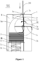
Figure 1 is an overall layout view of a recycle box according to an embodiment of the present application; -
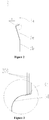
Figure 2 is a sectional view of abanknote guiding plate 3 inFigure 1 ; -
Figure 3 is a partially enlarged view showing an area I of thebanknote guiding plate 3 inFigure 2 ; -
Figure 4 is a schematic view of the recycle box inFigure 1 in a banknote-feeding state; -
Figure 5 is a schematic view of the recycle box inFigure 1 showing that its impeller conveys banknotes; -
Figure 6 is a schematic view of a banknote stacking plate of the recycle box inFigure 1 when stacking banknotes; -
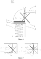
Figure 7 is a schematic view of the recycle box inFigure 1 showing the number of blades and banknote conveying manner; -
Figure 8 is a schematic view of impellers and banknote guiding elastic strips of the recycle box inFigure 1 being alternately arranged; and -
Figure 9 is a schematic view of variations of a top surface for stacking banknotes of thebanknote stacking plate 6 of the recycle box inFigure 1 . - A recycle box is provided according to an embodiment of the present application which can be configured to recycle media such as banknotes (paper currencies), checks or securities. In this embodiment, the structure and connecting relationship of the components of the recycle box are explained by taking banknotes (paper currencies) as the recycled media of the
recycle box 100. It is to be noted that, the type of the media to be recycled can be paper-type articles such as banknotes (paper currencies), checks or securities, and is not specifically limited in practical application. - The technical solutions in the embodiments of the present application will be described clearly and completely hereinafter in conjunction with the drawings in the embodiments of the present application. Apparently, the described embodiments are only a part of the embodiments of the present application, rather than all embodiments. Based on the embodiments in the present application, all of other embodiments, made by those skilled in the art without any creative efforts, fall into the scope of the present application.
- As shown in
Figure 1 , arecycle box 100 includes a box door 8 and abox bottom housing 1 connected to the box door 8. The box door 8 may be opened to allow the banknotes inside thebox bottom housing 1 to be taken out. - A recycle inlet is provided at the top of the
box bottom housing 1. A guideelastic strip 2, abanknote guiding plate 3, animpeller 4 and abanknote stacking plate 6 are fixed inside thebox bottom housing 1. Anelastic component 5 is connected between thebanknote stacking plate 6 and a bottom portion of thebox bottom housing 1. The guideelastic strip 2 and thebanknote guiding plate 3 are arranged vertically and arranged face to face, and a gap is included between the guide elastic strip and the banknote guiding plate and defines a recycle passage. Thebanknote guiding plate 3 is provided with a first stopper and the banknotes fall onto the stopper after passing through the recycle inlet and the recycle passage. Thebanknote guiding plate 3 is provided with an opening for aflexible blade 4a of theimpeller 4 to pass through, and theflexible blade 4a may rotate by 360 degrees about an impeller shaft. When being rotated out of the opening of thebanknote guiding plate 3, theflexible blade 4a conveys the banknotes on the first stopper of thebanknote guiding plate 3 onto thebanknote stacking plate 6 and thebanknote stacking plate 6 is configured to stack banknotes. - With the technical solution described above, since the guide elastic strip, the banknote guiding plate, the impeller and the banknote stacking plate are fixed inside the box bottom housing of the recycle box, and the guide elastic strip and the banknote guiding plate are arranged vertically and arranged face to face, and a gap, i.e. the recycle passage is formed between the guide elastic strip and the banknote guiding plate, and the recycle passage is used for receiving the fallen recycled media, when the recycled media fall onto the first stopper of the banknote guiding plate configured to temporarily store the recycled media after passing through the recycle inlet and the recycle passage, the flexible blade of the impeller passes through the opening of the banknote guiding plate and is rotated out of the opening of the banknote guiding plate, and the flexible blade conveys the recycled media on the first stopper onto the banknote stacking plate. In the rotation process, as the recycled media increase, the flexible blade may be deformed to a certain extent when coming into contact with the banknote stacking plate and may not be restored to the original shape. With the technical solution, since the flexible blade may be continually deformed, the impeller may have a small diameter, and thus the volume of the recycle box may be reduced accordingly.
- Preferably, as shown in
Figures 2 and 3 , thebanknote guiding plate 3 includes a first banknote guiding vertical surface 3a, a banknote guiding toothed surface 3c, a banknote guiding circular-arc surface 3d, a banknote guiding inclined surface 3e, and a second banknote guidingvertical surface 3b which are connected in the listed sequence. The first stopper described above is the banknote guiding toothed surface 3c. The banknote guiding circular-arc surface 3d is transitionally connected to the first banknote guiding vertical surface 3a through the banknote guiding toothed surface 3c with saw teeth. The first banknote guiding vertical surface 3a extends upward from a tip end on a right side of the banknote guiding toothed surface 3c. The second banknote guidingvertical surface 3b is located below the banknote guiding circular-arc surface 3d which is coplanar with the first banknote guiding vertical surface 3a. The second banknote guidingvertical surface 3b is transitionally connected to the banknote guiding circular-arc surface 3d through the banknote guiding inclined surface 3e. - The toothed saw teeth of the banknote guiding toothed surface 3c function as a cushion when a banknote falls onto the banknote guiding toothed surface 3c, and allows
several banknotes 200 to be vertically arranged on the banknote guiding toothed surface 3c at the same time. The uppermost banknote may be conveyed toward the second banknote guidingvertical surface 3b of thebanknote guiding plate 3 when the blade of theimpeller 4 slides toward the top surface of thebanknote stacking plate 6, which is advantageous for order stacking of the collected banknotes. - The
impeller 4 may be mounted at an axis position of the banknote guiding circular-arc surface 3d of thebanknote guiding plate 3. Theimpeller 4 is provided with uniformly distributedblades 4a, each of theblades 4a has flexibility functioning to allow the size of the housing to be reduced, and has a certain rigidity functioning to stabilize a rotational conveying of the banknotes. - Preferably, as shown in
Figure 1 , the guideelastic strip 2 includes an guidinginclined surface 2a and a guidingvertical surface 2b connected to a lower end of the banknote guiding inclined surface. A distance between the guidinginclined surface 2a and the first banknote guiding vertical surface 3a of thebanknote guiding plate 3 is decreased gradually. The distance between the guidingvertical surface 2b and the first banknote guiding vertical surface 3a is the same as a minimum distance between the guidinginclined surface 2a and the first banknote guiding vertical surface 3a. - The reason why the distance between the guiding
inclined surface 2a and the first banknote guiding vertical surface 3a of thebanknote guiding plate 3 is gradually decreased is that: therecycle box 100, as a module required to be frequently removed so as to be opened for counting of banknotes, is required to hand over banknotes with an original passage opening of the machine core. In order to enable the banknotes to enter he recyclebox 100 so as to realize a reliable banknote-passing, a box body inlet passage of the recycle box should be wider; the gap between the guidingvertical surface 2b and the first banknote guiding vertical surface 3a of thebanknote guiding plate 3 is equal to the minimum gap between the guidinginclined surface 2a and the first banknote guiding vertical surface 3 a of thebanknote guiding plate 3 to ensure the banknotes to be reliably and stably transferred to the passage with a normal width from the wider passage. - Preferably, as shown in
Figure 1 , the recycle inlet is formed by aleft guide tooth 1a and aright guide tooth 1b, which is convenient for handing over the banknotes entering from other modules. The distance from the banknote guiding toothed surface 3c to theleft guide tooth 1a and theright guide tooth 1b of the recycle inlet of the boxbottom housing 1 should be greater than a maximum width of the banknotes to be collected. The guideelastic strip 2 may be mounted at an inner side of a lower portion of theleft guide tooth 1a of the boxbottom housing 1. There is a gap between the guidinginclined surface 2a and the first banknote guiding vertical surface 3a of thebanknote guiding plate 3, and the gap defines a recycle passage. A maximum width of the gap between the guidinginclined surface 2a and the first banknote guiding vertical surface 3a of thebanknote guiding plate 3 is equal to a width of a gap between theleft guide tooth 1a and theright guide tooth 1b or is greater than the width of the gap between theleft guide tooth 1a and theright guide tooth 1b by 1mm to 3mm. The guidingvertical surface 2b and the first banknote guiding vertical surface 3a face to face with a gap therebetween ranging from 2mm to 5mm. Thebanknote guiding plate 3 is mounted at an inner side of a lower portion of theright guide tooth 1b of the boxbottom housing 1, and the first banknote guiding vertical surface 3a is coplanar with a banknote-passing surface of theright guide tooth 1b or slightly deviates rightwards with respect to the banknote-passing surface. - Preferably, the box door 8 is hinged to the box
bottom housing 1, and is capable of rotating about a door shaft 8c to be opened for counting the banknotes. A circular-arc-shaped guidingfillet 8a is provided at an inner side of an upper part of the box door 8. A stacking space for the banknotes is defined by the second banknote guidingvertical surface 3b of thebanknote guiding plate 3 and the third banknote guidingvertical surface 8b of the box door 8 together. Thebanknote stacking plate 6 is located between the third banknote guidingvertical surface 8b and the second banknote guidingvertical surface 3b. The space is slightly greater than the width of the banknotes to be collected, for example the space is greater than the width of the banknotes to be collected by 3mm to 5mm. - Preferably, the elastic component may be a banknote stacking
plate restoring spring 5, the shape of which is not limited to a tapered or cylindrical shape. Thebanknote stacking plate 6 is mounted at a central top of the banknote stackingplate restoring spring 5. Whether or not thebanknote stacking plate 6 is equipped with a shaft having a guide effect does not affect the realization of the functions of the mechanism. - Preferably, as shown in
Figures 1 and7 , theimpeller 4 has at least one blade, and the number of the blades is not limited to four as illustrated. The orderliness degree of thebanknotes 200 being stacked by theimpeller 4 depends on the number of the blades, a rotational speed of the impeller and a banknote feeding speed. The manner in which the banknotes are conveyed is determined by the number of the blades when the rotational speed of the blades and the speed of advancement of the banknotes are constant. As shown inFigure 7a , the time during which theimpeller 4a as shown inFigure 1 (horizontally arranged) is switched to theimpeller 4b as shown inFigure 7 is just sufficient for onebanknote 200 to enter. In this case, if the number of the blades is less than four, more than onebanknote 200 is allowed to be temporarily stacked on the banknote guiding toothed surface 3c of thebanknote guiding plate 3. The banknotes are forced to rotate by theblade 4b when being conveyed, and theblade 4b is not spaced apart from thebanknote stacking plate 6. As shown inFigure 7b , if the number of the blades is greater than four, thebanknotes 200 are pressed by the blades to slide over the banknote guiding circular-arc fillet 8a on thebox door 1, and theblades 4b, 4c are respectively located at a front side and a rear side of the banknote, which is advantageous for the turnover conveying of the banknotes, i.e., thebanknotes 200 are spaced apart from thebanknote stacking plate 6 by the blade 4c. If the banknotes are not spaced apart from thebanknote stacking plate 6 by the blade 4c, thebanknotes 200 may fall onto thebanknote stacking plate 6 freely when theimpeller 4 is stopped due to a failure, which is disadvantageous for the order stacking of the banknotes. The spaced design can effectively avoid this issue. - Preferably, as shown in
Figure 8 , the number of theimpellers 4 is at least two, and the guide elastic strip may be more than one. The guideelastic strip 2 is located betweenadjacent impellers 4, and theimpellers 4 and the guideelastic strips 2 are alternately arranged. - Preferably, as shown in
Figure 9 , the shape of the top surface of thebanknote stacking plate 6 may be changed into various forms, such as aninclined plane 61 or acambered surface 62, to reduce a driving force required when the blade slides, which may not affect the function of the present application. - The operation process of the recycle box will be explained in conjunction with
Figures 3 to 6 , the drive and detection systems of theimpeller 4 are not illustrated and theimpeller 4 is unidirectionally rotated counterclockwise. - As shown in
Figure 4 , when there is no banknote on thebanknote stacking plate 6, the banknote stacking plate is located at an upper limit position under the action of the banknote stackingplate restoring spring 5. - When the banknotes are required to enter the
recycle box 100, a control section issues an instruction such that theimpeller 4 rotates counterclockwise, and the banknotes, after entering via the space between theleft guide tooth 1a and theright guide tooth 1b, fall along the guidinginclined surface 2a of the guideelastic strip 2, and the recycle passage defined by the guidingvertical surface 2b and the first banknote guiding vertical surface 3a of thebanknote guiding plate 3 in sequence onto the banknote guiding toothed surface 3c of the banknote guiding plate. - As shown in
Figures 4 and5 , when one of the blades of theimpellers 4, such as theblade 4b, is rotated out of the opening of thebanknote guiding plate 3, thebanknotes 200 may be pressed against a lower portion of theimpeller 4b in the rotational direction while being conveyed to thebanknote stacking plate 6 along thebanknote guiding plate 3. - After the banknotes enter continuously, the banknote stacking
plate restoring spring 5 is compressed under the deadweight of thebanknote stacking plate 6, the weight of the banknotes stacked and a pressing component force generated by the flexible blades of theimpeller 4 sliding across the top of the banknotes stacked, thus vacating an upper part space for collecting banknotes, as shown inFigure 6 , till the banknote stackingplate restoring spring 5 is pressed to a maximum degree and it is detected that the capacity of therecycle box 100 reaches the limit (the detection system is not shown). - A control system may control the operation timing of the
impeller 4, and theimpeller 4 may always rotate counterclockwise, which will not affect the functions described in this application.
Claims (10)
- A recycle box, comprising a box door and a box bottom housing, wherein:a recycle inlet is provided at a top of the box bottom housing, a guide elastic strip, a banknote guiding plate, an impeller and a banknote stacking plate configured to stack recycled media are fixed inside the box bottom housing;the impeller has a plurality of flexible blades, the guide elastic strip and the banknote guiding plate are arranged vertically and arranged face to face, there is a gap between the guide elastic strip and the banknote guiding plate, and the gap is a recycle passage;the banknote guiding plate is provided with a first stopper configured to place the recycled media and is provided with an opening configured to allow the flexible blades to pass through, the recycled media are placed on the first stopper after passing through the recycle inlet and the recycle passage, the flexible blades convey the recycled media on the first stopper onto the banknote stacking plate when the flexible blades are rotated out of the opening.
- The recycle box according to claim 1, wherein the banknote guiding plate comprises a first banknote guiding vertical surface, a banknote guiding toothed surface, a banknote guiding circular-arc surface, an banknote guiding inclined surface and a second banknote guiding vertical surface which are connected in the listed sequence, a gap is provided between the guide elastic strip and the first banknote guiding vertical surface, and the banknote guiding toothed surface is the first stopper and is configured to temporarily store the recycled media passing through the recycle inlet and the recycle passage sequentially.
- The recycle box according to claim 2, wherein the guide elastic strip comprises an guiding inclined surface and a guiding vertical surface connected to a lower end of the guiding inclined surface, a distance between the guiding inclined surface and the first banknote guiding vertical surface is decreased gradually, and a distance between the guiding vertical surface and the first banknote guiding vertical surface is equal to a minimum distance between the guiding inclined surface and the first banknote guiding vertical surface.
- The recycle box according to claim 3, wherein the recycle inlet is enclosed by a left guide tooth and a right guide tooth.
- The recycle box according to any one of claims 1 to 4, wherein the number of the impeller is at least two, and the guide elastic strip is positioned between each adjacent impellers.
- The recycle box according to claim 4, wherein a maximum distance between the guiding inclined surface and the first banknote guiding vertical surface is equal to a distance between the left guide tooth and the right guide tooth or is greater than the distance between the left guide tooth and the right guide tooth by 1mm to 3mm.
- The recycle box according to claim 3 or 4, wherein the distance between the guiding vertical surface and the first banknote guiding vertical surface ranges from 2mm to 5mm.
- The recycle box according to claim 1, wherein the banknote stacking plate is a flat surface or an inclined surface.
- The recycle box according to claim 2, wherein a banknote guiding circular-arc fillet and a third banknote guiding vertical surface are provided inside the box door, and the banknote stacking plate is located between the third banknote guiding vertical surface and the second banknote guiding vertical surface.
- The recycle box according to claim 1, wherein an elastic component is connected between the banknote stacking plate and a bottom portion of the box bottom housing, and the elastic component is compressed by the banknote stacking plate when the recycled media are stacked on the banknote stacking plate.
Applications Claiming Priority (2)
| Application Number | Priority Date | Filing Date | Title |
|---|---|---|---|
| CN201510242885.0A CN104943948B (en) | 2015-05-13 | 2015-05-13 | Recycling bin |
| PCT/CN2016/078535 WO2016180102A1 (en) | 2015-05-13 | 2016-04-06 | Recycling bin |
Publications (3)
| Publication Number | Publication Date |
|---|---|
| EP3296231A1 true EP3296231A1 (en) | 2018-03-21 |
| EP3296231A4 EP3296231A4 (en) | 2018-05-30 |
| EP3296231B1 EP3296231B1 (en) | 2019-07-17 |
Family
ID=54159115
Family Applications (1)
| Application Number | Title | Priority Date | Filing Date |
|---|---|---|---|
| EP16791952.1A Active EP3296231B1 (en) | 2015-05-13 | 2016-04-06 | Recycling bin |
Country Status (8)
| Country | Link |
|---|---|
| US (1) | US10287126B2 (en) |
| EP (1) | EP3296231B1 (en) |
| CN (1) | CN104943948B (en) |
| HK (1) | HK1250974A1 (en) |
| RU (1) | RU2669160C1 (en) |
| TR (1) | TR201911191T4 (en) |
| WO (1) | WO2016180102A1 (en) |
| ZA (1) | ZA201707629B (en) |
Families Citing this family (8)
| Publication number | Priority date | Publication date | Assignee | Title |
|---|---|---|---|---|
| CN104943948B (en) | 2015-05-13 | 2017-04-26 | 广州广电运通金融电子股份有限公司 | Recycling bin |
| CN106296986B (en) * | 2016-08-05 | 2023-02-28 | 深圳怡化电脑股份有限公司 | Paper money input/output device and automatic paper money transaction device |
| CN106710068A (en) * | 2017-02-10 | 2017-05-24 | 深圳怡化电脑股份有限公司 | Paper money temporary storage module and automatic teller machine |
| CN106780986A (en) * | 2017-02-10 | 2017-05-31 | 深圳怡化电脑股份有限公司 | The banknote stack apparatus of cash box and cash box mechanism |
| CN109132154B (en) * | 2018-08-27 | 2021-05-28 | 东方通信股份有限公司 | Thin slice class medium containing box |
| CN109592452A (en) * | 2018-12-26 | 2019-04-09 | 前海拉斯曼智能系统(深圳)有限公司 | Inhale paper anti-dual sheet sawtooth feeding distribution mechanism |
| US11600150B2 (en) * | 2019-10-25 | 2023-03-07 | Hyosung TNS Inc. | Medium stacking sheet and medium separating and stacking apparatus including the same |
| CN113636150A (en) * | 2021-06-29 | 2021-11-12 | 浙江水墨江南新材料科技有限公司 | Special interval upset machine of floor processing production |
Family Cites Families (16)
| Publication number | Priority date | Publication date | Assignee | Title |
|---|---|---|---|---|
| US3166313A (en) * | 1960-08-27 | 1965-01-19 | Telefunken Patent | Article handling device |
| US4275874A (en) * | 1979-02-21 | 1981-06-30 | Brandt-Pra, Inc. | Extended stacker |
| JP4791631B2 (en) * | 2000-12-26 | 2011-10-12 | 株式会社東芝 | Paper sheet processing equipment |
| JP3880503B2 (en) | 2002-10-16 | 2007-02-14 | 日立オムロンターミナルソリューションズ株式会社 | Paper sheet stacking and feeding device |
| JP2005263446A (en) * | 2004-03-19 | 2005-09-29 | Hitachi Omron Terminal Solutions Corp | Sheet handling device, and runner used therein |
| JP2007323130A (en) * | 2006-05-30 | 2007-12-13 | Laurel Seiki Kk | Bill processor |
| JP4998105B2 (en) * | 2007-06-18 | 2012-08-15 | 沖電気工業株式会社 | Medium stacking and feeding device |
| JP4966117B2 (en) * | 2007-07-09 | 2012-07-04 | 日立オムロンターミナルソリューションズ株式会社 | Paper sheet stacking device |
| DE102008018961A1 (en) | 2008-04-15 | 2009-10-29 | Wincor Nixdorf International Gmbh | Single-sheet handling device for entering rectangular single sheets into a container |
| JP5141577B2 (en) * | 2009-01-27 | 2013-02-13 | 沖電気工業株式会社 | Paper sheet separation and accumulation mechanism |
| JP5482283B2 (en) * | 2010-02-19 | 2014-05-07 | 沖電気工業株式会社 | Banknote storage and banknote depositing and dispensing machine equipped with the same |
| JP6478442B2 (en) * | 2013-02-12 | 2019-03-06 | 沖電気工業株式会社 | Medium stacking apparatus and medium processing apparatus |
| JP6064786B2 (en) * | 2013-05-24 | 2017-01-25 | 沖電気工業株式会社 | Medium stacking apparatus and medium processing apparatus |
| JP6127752B2 (en) * | 2013-06-12 | 2017-05-17 | 沖電気工業株式会社 | Medium protection device and medium separation / integration device |
| JP6290563B2 (en) * | 2013-09-13 | 2018-03-07 | グローリー株式会社 | Paper sheet stacking and feeding device |
| CN104943948B (en) * | 2015-05-13 | 2017-04-26 | 广州广电运通金融电子股份有限公司 | Recycling bin |
-
2015
- 2015-05-13 CN CN201510242885.0A patent/CN104943948B/en active Active
-
2016
- 2016-04-06 TR TR2019/11191T patent/TR201911191T4/en unknown
- 2016-04-06 US US15/571,815 patent/US10287126B2/en not_active Expired - Fee Related
- 2016-04-06 EP EP16791952.1A patent/EP3296231B1/en active Active
- 2016-04-06 WO PCT/CN2016/078535 patent/WO2016180102A1/en active Application Filing
- 2016-04-06 RU RU2017141724A patent/RU2669160C1/en not_active IP Right Cessation
-
2017
- 2017-11-10 ZA ZA2017/07629A patent/ZA201707629B/en unknown
-
2018
- 2018-08-13 HK HK18110316.6A patent/HK1250974A1/en unknown
Also Published As
| Publication number | Publication date |
|---|---|
| CN104943948A (en) | 2015-09-30 |
| HK1250974A1 (en) | 2019-01-18 |
| CN104943948B (en) | 2017-04-26 |
| TR201911191T4 (en) | 2019-08-21 |
| EP3296231A4 (en) | 2018-05-30 |
| US10287126B2 (en) | 2019-05-14 |
| EP3296231B1 (en) | 2019-07-17 |
| ZA201707629B (en) | 2018-11-28 |
| US20180346198A1 (en) | 2018-12-06 |
| RU2669160C1 (en) | 2018-10-08 |
| WO2016180102A1 (en) | 2016-11-17 |
Similar Documents
| Publication | Publication Date | Title |
|---|---|---|
| EP3296231A1 (en) | Recycling bin | |
| US10071869B2 (en) | Medium feeder and image reading apparatus | |
| EP3275819B1 (en) | Paper money stacking apparatus and paper money processing device | |
| EP2980763A1 (en) | Banknote processing device and cash-out and cash-in mechanism thereof | |
| JP5771894B2 (en) | Paper sheet stacking device | |
| US9592978B2 (en) | Medium protection device and medium separating and stacking device | |
| RU2637897C1 (en) | Device for laying carriers and device of transactions with carriers | |
| JP5983334B2 (en) | Position adjusting device and paper sheet processing device | |
| EP2919207A1 (en) | Paper sheet type medium stacking device | |
| US2991075A (en) | Bed plate for a card feed | |
| JP5286295B2 (en) | Paper sheet storage device | |
| JP6064786B2 (en) | Medium stacking apparatus and medium processing apparatus | |
| US11113920B2 (en) | Banknote stacking and separating apparatus and banknote processing device | |
| JP2010013221A (en) | Paper sheet handling device | |
| JP5913610B2 (en) | Paper sheet stacking device | |
| JP2012027545A (en) | Paper sheet transaction device | |
| KR101414754B1 (en) | Paper sheet feeding device and paper sheet processing apparatus | |
| JP2017043479A (en) | Paper sheet stacking mechanism and paper sheet handling apparatus | |
| EP2227792B1 (en) | Apparatus for transferring paper media and automatic teller machine having the same | |
| US20200369482A1 (en) | Paper sheet separation device and paper sheet separation method | |
| JP2018122954A (en) | Sheet conveying device | |
| JPWO2014054146A1 (en) | Paper sheet handling equipment | |
| US8888095B1 (en) | Processing apparatus of cards and sheets | |
| JP2010052884A (en) | Paper sheet handling device | |
| CN211545433U (en) | Sheet-like medium collecting and separating device and depositing and dispensing machine |
Legal Events
| Date | Code | Title | Description |
|---|---|---|---|
| STAA | Information on the status of an ep patent application or granted ep patent |
Free format text: STATUS: THE INTERNATIONAL PUBLICATION HAS BEEN MADE |
|
| PUAI | Public reference made under article 153(3) epc to a published international application that has entered the european phase |
Free format text: ORIGINAL CODE: 0009012 |
|
| STAA | Information on the status of an ep patent application or granted ep patent |
Free format text: STATUS: REQUEST FOR EXAMINATION WAS MADE |
|
| 17P | Request for examination filed |
Effective date: 20171024 |
|
| AK | Designated contracting states |
Kind code of ref document: A1 Designated state(s): AL AT BE BG CH CY CZ DE DK EE ES FI FR GB GR HR HU IE IS IT LI LT LU LV MC MK MT NL NO PL PT RO RS SE SI SK SM TR |
|
| AX | Request for extension of the european patent |
Extension state: BA ME |
|
| RIC1 | Information provided on ipc code assigned before grant |
Ipc: G07D 11/00 20060101ALI20180419BHEP Ipc: B65D 25/10 20060101ALI20180419BHEP Ipc: B65H 29/52 20060101ALI20180419BHEP Ipc: B65D 85/62 20060101AFI20180419BHEP |
|
| A4 | Supplementary search report drawn up and despatched |
Effective date: 20180430 |
|
| DAV | Request for validation of the european patent (deleted) | ||
| DAX | Request for extension of the european patent (deleted) | ||
| RIC1 | Information provided on ipc code assigned before grant |
Ipc: B65H 31/10 20060101ALI20181031BHEP Ipc: B65D 25/10 20060101ALI20181031BHEP Ipc: B65H 29/52 20060101ALI20181031BHEP Ipc: B65D 85/62 20060101AFI20181031BHEP Ipc: G07D 11/00 20060101ALI20181031BHEP Ipc: B65H 29/40 20060101ALI20181031BHEP |
|
| GRAP | Despatch of communication of intention to grant a patent |
Free format text: ORIGINAL CODE: EPIDOSNIGR1 |
|
| STAA | Information on the status of an ep patent application or granted ep patent |
Free format text: STATUS: GRANT OF PATENT IS INTENDED |
|
| INTG | Intention to grant announced |
Effective date: 20181219 |
|
| REG | Reference to a national code |
Ref country code: HK Ref legal event code: DE Ref document number: 1250974 Country of ref document: HK |
|
| GRAS | Grant fee paid |
Free format text: ORIGINAL CODE: EPIDOSNIGR3 |
|
| GRAA | (expected) grant |
Free format text: ORIGINAL CODE: 0009210 |
|
| STAA | Information on the status of an ep patent application or granted ep patent |
Free format text: STATUS: THE PATENT HAS BEEN GRANTED |
|
| AK | Designated contracting states |
Kind code of ref document: B1 Designated state(s): AL AT BE BG CH CY CZ DE DK EE ES FI FR GB GR HR HU IE IS IT LI LT LU LV MC MK MT NL NO PL PT RO RS SE SI SK SM TR |
|
| REG | Reference to a national code |
Ref country code: GB Ref legal event code: FG4D |
|
| REG | Reference to a national code |
Ref country code: CH Ref legal event code: EP |
|
| REG | Reference to a national code |
Ref country code: IE Ref legal event code: FG4D |
|
| REG | Reference to a national code |
Ref country code: DE Ref legal event code: R096 Ref document number: 602016017111 Country of ref document: DE |
|
| REG | Reference to a national code |
Ref country code: AT Ref legal event code: REF Ref document number: 1155662 Country of ref document: AT Kind code of ref document: T Effective date: 20190815 |
|
| REG | Reference to a national code |
Ref country code: NL Ref legal event code: MP Effective date: 20190717 |
|
| REG | Reference to a national code |
Ref country code: LT Ref legal event code: MG4D |
|
| PG25 | Lapsed in a contracting state [announced via postgrant information from national office to epo] |
Ref country code: SE Free format text: LAPSE BECAUSE OF FAILURE TO SUBMIT A TRANSLATION OF THE DESCRIPTION OR TO PAY THE FEE WITHIN THE PRESCRIBED TIME-LIMIT Effective date: 20190717 Ref country code: LT Free format text: LAPSE BECAUSE OF FAILURE TO SUBMIT A TRANSLATION OF THE DESCRIPTION OR TO PAY THE FEE WITHIN THE PRESCRIBED TIME-LIMIT Effective date: 20190717 Ref country code: BG Free format text: LAPSE BECAUSE OF FAILURE TO SUBMIT A TRANSLATION OF THE DESCRIPTION OR TO PAY THE FEE WITHIN THE PRESCRIBED TIME-LIMIT Effective date: 20191017 Ref country code: PT Free format text: LAPSE BECAUSE OF FAILURE TO SUBMIT A TRANSLATION OF THE DESCRIPTION OR TO PAY THE FEE WITHIN THE PRESCRIBED TIME-LIMIT Effective date: 20191118 Ref country code: NL Free format text: LAPSE BECAUSE OF FAILURE TO SUBMIT A TRANSLATION OF THE DESCRIPTION OR TO PAY THE FEE WITHIN THE PRESCRIBED TIME-LIMIT Effective date: 20190717 Ref country code: NO Free format text: LAPSE BECAUSE OF FAILURE TO SUBMIT A TRANSLATION OF THE DESCRIPTION OR TO PAY THE FEE WITHIN THE PRESCRIBED TIME-LIMIT Effective date: 20191017 Ref country code: FI Free format text: LAPSE BECAUSE OF FAILURE TO SUBMIT A TRANSLATION OF THE DESCRIPTION OR TO PAY THE FEE WITHIN THE PRESCRIBED TIME-LIMIT Effective date: 20190717 Ref country code: HR Free format text: LAPSE BECAUSE OF FAILURE TO SUBMIT A TRANSLATION OF THE DESCRIPTION OR TO PAY THE FEE WITHIN THE PRESCRIBED TIME-LIMIT Effective date: 20190717 |
|
| PG25 | Lapsed in a contracting state [announced via postgrant information from national office to epo] |
Ref country code: LV Free format text: LAPSE BECAUSE OF FAILURE TO SUBMIT A TRANSLATION OF THE DESCRIPTION OR TO PAY THE FEE WITHIN THE PRESCRIBED TIME-LIMIT Effective date: 20190717 Ref country code: GR Free format text: LAPSE BECAUSE OF FAILURE TO SUBMIT A TRANSLATION OF THE DESCRIPTION OR TO PAY THE FEE WITHIN THE PRESCRIBED TIME-LIMIT Effective date: 20191018 Ref country code: IS Free format text: LAPSE BECAUSE OF FAILURE TO SUBMIT A TRANSLATION OF THE DESCRIPTION OR TO PAY THE FEE WITHIN THE PRESCRIBED TIME-LIMIT Effective date: 20191117 Ref country code: AL Free format text: LAPSE BECAUSE OF FAILURE TO SUBMIT A TRANSLATION OF THE DESCRIPTION OR TO PAY THE FEE WITHIN THE PRESCRIBED TIME-LIMIT Effective date: 20190717 Ref country code: RS Free format text: LAPSE BECAUSE OF FAILURE TO SUBMIT A TRANSLATION OF THE DESCRIPTION OR TO PAY THE FEE WITHIN THE PRESCRIBED TIME-LIMIT Effective date: 20190717 Ref country code: ES Free format text: LAPSE BECAUSE OF FAILURE TO SUBMIT A TRANSLATION OF THE DESCRIPTION OR TO PAY THE FEE WITHIN THE PRESCRIBED TIME-LIMIT Effective date: 20190717 |
|
| PG25 | Lapsed in a contracting state [announced via postgrant information from national office to epo] |
Ref country code: DK Free format text: LAPSE BECAUSE OF FAILURE TO SUBMIT A TRANSLATION OF THE DESCRIPTION OR TO PAY THE FEE WITHIN THE PRESCRIBED TIME-LIMIT Effective date: 20190717 Ref country code: PL Free format text: LAPSE BECAUSE OF FAILURE TO SUBMIT A TRANSLATION OF THE DESCRIPTION OR TO PAY THE FEE WITHIN THE PRESCRIBED TIME-LIMIT Effective date: 20190717 Ref country code: EE Free format text: LAPSE BECAUSE OF FAILURE TO SUBMIT A TRANSLATION OF THE DESCRIPTION OR TO PAY THE FEE WITHIN THE PRESCRIBED TIME-LIMIT Effective date: 20190717 Ref country code: RO Free format text: LAPSE BECAUSE OF FAILURE TO SUBMIT A TRANSLATION OF THE DESCRIPTION OR TO PAY THE FEE WITHIN THE PRESCRIBED TIME-LIMIT Effective date: 20190717 |
|
| PG25 | Lapsed in a contracting state [announced via postgrant information from national office to epo] |
Ref country code: CZ Free format text: LAPSE BECAUSE OF FAILURE TO SUBMIT A TRANSLATION OF THE DESCRIPTION OR TO PAY THE FEE WITHIN THE PRESCRIBED TIME-LIMIT Effective date: 20190717 Ref country code: SK Free format text: LAPSE BECAUSE OF FAILURE TO SUBMIT A TRANSLATION OF THE DESCRIPTION OR TO PAY THE FEE WITHIN THE PRESCRIBED TIME-LIMIT Effective date: 20190717 Ref country code: IS Free format text: LAPSE BECAUSE OF FAILURE TO SUBMIT A TRANSLATION OF THE DESCRIPTION OR TO PAY THE FEE WITHIN THE PRESCRIBED TIME-LIMIT Effective date: 20200224 Ref country code: SM Free format text: LAPSE BECAUSE OF FAILURE TO SUBMIT A TRANSLATION OF THE DESCRIPTION OR TO PAY THE FEE WITHIN THE PRESCRIBED TIME-LIMIT Effective date: 20190717 |
|
| REG | Reference to a national code |
Ref country code: DE Ref legal event code: R097 Ref document number: 602016017111 Country of ref document: DE |
|
| PLBE | No opposition filed within time limit |
Free format text: ORIGINAL CODE: 0009261 |
|
| STAA | Information on the status of an ep patent application or granted ep patent |
Free format text: STATUS: NO OPPOSITION FILED WITHIN TIME LIMIT |
|
| PG2D | Information on lapse in contracting state deleted |
Ref country code: IS |
|
| 26N | No opposition filed |
Effective date: 20200603 |
|
| PG25 | Lapsed in a contracting state [announced via postgrant information from national office to epo] |
Ref country code: SI Free format text: LAPSE BECAUSE OF FAILURE TO SUBMIT A TRANSLATION OF THE DESCRIPTION OR TO PAY THE FEE WITHIN THE PRESCRIBED TIME-LIMIT Effective date: 20190717 |
|
| REG | Reference to a national code |
Ref country code: DE Ref legal event code: R119 Ref document number: 602016017111 Country of ref document: DE |
|
| PG25 | Lapsed in a contracting state [announced via postgrant information from national office to epo] |
Ref country code: MC Free format text: LAPSE BECAUSE OF FAILURE TO SUBMIT A TRANSLATION OF THE DESCRIPTION OR TO PAY THE FEE WITHIN THE PRESCRIBED TIME-LIMIT Effective date: 20190717 |
|
| REG | Reference to a national code |
Ref country code: CH Ref legal event code: PL |
|
| PG25 | Lapsed in a contracting state [announced via postgrant information from national office to epo] |
Ref country code: LI Free format text: LAPSE BECAUSE OF NON-PAYMENT OF DUE FEES Effective date: 20200430 Ref country code: LU Free format text: LAPSE BECAUSE OF NON-PAYMENT OF DUE FEES Effective date: 20200406 Ref country code: DE Free format text: LAPSE BECAUSE OF NON-PAYMENT OF DUE FEES Effective date: 20201103 Ref country code: CH Free format text: LAPSE BECAUSE OF NON-PAYMENT OF DUE FEES Effective date: 20200430 Ref country code: FR Free format text: LAPSE BECAUSE OF NON-PAYMENT OF DUE FEES Effective date: 20200430 |
|
| REG | Reference to a national code |
Ref country code: BE Ref legal event code: MM Effective date: 20200430 |
|
| REG | Reference to a national code |
Ref country code: AT Ref legal event code: UEP Ref document number: 1155662 Country of ref document: AT Kind code of ref document: T Effective date: 20190717 |
|
| PG25 | Lapsed in a contracting state [announced via postgrant information from national office to epo] |
Ref country code: BE Free format text: LAPSE BECAUSE OF NON-PAYMENT OF DUE FEES Effective date: 20200430 |
|
| GBPC | Gb: european patent ceased through non-payment of renewal fee |
Effective date: 20200406 |
|
| PG25 | Lapsed in a contracting state [announced via postgrant information from national office to epo] |
Ref country code: IE Free format text: LAPSE BECAUSE OF NON-PAYMENT OF DUE FEES Effective date: 20200406 Ref country code: GB Free format text: LAPSE BECAUSE OF NON-PAYMENT OF DUE FEES Effective date: 20200406 |
|
| PG25 | Lapsed in a contracting state [announced via postgrant information from national office to epo] |
Ref country code: IT Free format text: LAPSE BECAUSE OF NON-PAYMENT OF DUE FEES Effective date: 20200406 |
|
| PG25 | Lapsed in a contracting state [announced via postgrant information from national office to epo] |
Ref country code: MT Free format text: LAPSE BECAUSE OF FAILURE TO SUBMIT A TRANSLATION OF THE DESCRIPTION OR TO PAY THE FEE WITHIN THE PRESCRIBED TIME-LIMIT Effective date: 20190717 Ref country code: CY Free format text: LAPSE BECAUSE OF FAILURE TO SUBMIT A TRANSLATION OF THE DESCRIPTION OR TO PAY THE FEE WITHIN THE PRESCRIBED TIME-LIMIT Effective date: 20190717 |
|
| REG | Reference to a national code |
Ref country code: AT Ref legal event code: MM01 Ref document number: 1155662 Country of ref document: AT Kind code of ref document: T Effective date: 20210406 |
|
| PG25 | Lapsed in a contracting state [announced via postgrant information from national office to epo] |
Ref country code: MK Free format text: LAPSE BECAUSE OF FAILURE TO SUBMIT A TRANSLATION OF THE DESCRIPTION OR TO PAY THE FEE WITHIN THE PRESCRIBED TIME-LIMIT Effective date: 20190717 |
|
| PG25 | Lapsed in a contracting state [announced via postgrant information from national office to epo] |
Ref country code: AT Free format text: LAPSE BECAUSE OF NON-PAYMENT OF DUE FEES Effective date: 20210406 |