EP3296215A1 - Mount mechanism for accessory gearbox - Google Patents
Mount mechanism for accessory gearbox Download PDFInfo
- Publication number
- EP3296215A1 EP3296215A1 EP15891748.4A EP15891748A EP3296215A1 EP 3296215 A1 EP3296215 A1 EP 3296215A1 EP 15891748 A EP15891748 A EP 15891748A EP 3296215 A1 EP3296215 A1 EP 3296215A1
- Authority
- EP
- European Patent Office
- Prior art keywords
- pair
- brackets
- link
- gear box
- accessory gear
- Prior art date
- Legal status (The legal status is an assumption and is not a legal conclusion. Google has not performed a legal analysis and makes no representation as to the accuracy of the status listed.)
- Granted
Links
Images


Classifications
-
- B—PERFORMING OPERATIONS; TRANSPORTING
- B64—AIRCRAFT; AVIATION; COSMONAUTICS
- B64D—EQUIPMENT FOR FITTING IN OR TO AIRCRAFT; FLIGHT SUITS; PARACHUTES; ARRANGEMENT OR MOUNTING OF POWER PLANTS OR PROPULSION TRANSMISSIONS IN AIRCRAFT
- B64D33/00—Arrangement in aircraft of power plant parts or auxiliaries not otherwise provided for
-
- B—PERFORMING OPERATIONS; TRANSPORTING
- B64—AIRCRAFT; AVIATION; COSMONAUTICS
- B64D—EQUIPMENT FOR FITTING IN OR TO AIRCRAFT; FLIGHT SUITS; PARACHUTES; ARRANGEMENT OR MOUNTING OF POWER PLANTS OR PROPULSION TRANSMISSIONS IN AIRCRAFT
- B64D27/00—Arrangement or mounting of power plants in aircraft; Aircraft characterised by the type or position of power plants
- B64D27/40—Arrangements for mounting power plants in aircraft
- B64D27/402—Arrangements for mounting power plants in aircraft comprising box like supporting frames, e.g. pylons or arrangements for embracing the power plant
-
- B—PERFORMING OPERATIONS; TRANSPORTING
- B64—AIRCRAFT; AVIATION; COSMONAUTICS
- B64D—EQUIPMENT FOR FITTING IN OR TO AIRCRAFT; FLIGHT SUITS; PARACHUTES; ARRANGEMENT OR MOUNTING OF POWER PLANTS OR PROPULSION TRANSMISSIONS IN AIRCRAFT
- B64D41/00—Power installations for auxiliary purposes
-
- F—MECHANICAL ENGINEERING; LIGHTING; HEATING; WEAPONS; BLASTING
- F02—COMBUSTION ENGINES; HOT-GAS OR COMBUSTION-PRODUCT ENGINE PLANTS
- F02C—GAS-TURBINE PLANTS; AIR INTAKES FOR JET-PROPULSION PLANTS; CONTROLLING FUEL SUPPLY IN AIR-BREATHING JET-PROPULSION PLANTS
- F02C7/00—Features, components parts, details or accessories, not provided for in, or of interest apart form groups F02C1/00 - F02C6/00; Air intakes for jet-propulsion plants
- F02C7/32—Arrangement, mounting, or driving, of auxiliaries
-
- F—MECHANICAL ENGINEERING; LIGHTING; HEATING; WEAPONS; BLASTING
- F16—ENGINEERING ELEMENTS AND UNITS; GENERAL MEASURES FOR PRODUCING AND MAINTAINING EFFECTIVE FUNCTIONING OF MACHINES OR INSTALLATIONS; THERMAL INSULATION IN GENERAL
- F16F—SPRINGS; SHOCK-ABSORBERS; MEANS FOR DAMPING VIBRATION
- F16F1/00—Springs
- F16F1/36—Springs made of rubber or other material having high internal friction, e.g. thermoplastic elastomers
- F16F1/373—Springs made of rubber or other material having high internal friction, e.g. thermoplastic elastomers characterised by having a particular shape
- F16F1/3732—Springs made of rubber or other material having high internal friction, e.g. thermoplastic elastomers characterised by having a particular shape having an annular or the like shape, e.g. grommet-type resilient mountings
-
- F—MECHANICAL ENGINEERING; LIGHTING; HEATING; WEAPONS; BLASTING
- F16—ENGINEERING ELEMENTS AND UNITS; GENERAL MEASURES FOR PRODUCING AND MAINTAINING EFFECTIVE FUNCTIONING OF MACHINES OR INSTALLATIONS; THERMAL INSULATION IN GENERAL
- F16F—SPRINGS; SHOCK-ABSORBERS; MEANS FOR DAMPING VIBRATION
- F16F15/00—Suppression of vibrations in systems; Means or arrangements for avoiding or reducing out-of-balance forces, e.g. due to motion
- F16F15/02—Suppression of vibrations of non-rotating, e.g. reciprocating systems; Suppression of vibrations of rotating systems by use of members not moving with the rotating systems
- F16F15/04—Suppression of vibrations of non-rotating, e.g. reciprocating systems; Suppression of vibrations of rotating systems by use of members not moving with the rotating systems using elastic means
- F16F15/08—Suppression of vibrations of non-rotating, e.g. reciprocating systems; Suppression of vibrations of rotating systems by use of members not moving with the rotating systems using elastic means with rubber springs ; with springs made of rubber and metal
-
- F—MECHANICAL ENGINEERING; LIGHTING; HEATING; WEAPONS; BLASTING
- F05—INDEXING SCHEMES RELATING TO ENGINES OR PUMPS IN VARIOUS SUBCLASSES OF CLASSES F01-F04
- F05D—INDEXING SCHEME FOR ASPECTS RELATING TO NON-POSITIVE-DISPLACEMENT MACHINES OR ENGINES, GAS-TURBINES OR JET-PROPULSION PLANTS
- F05D2260/00—Function
- F05D2260/30—Retaining components in desired mutual position
-
- F—MECHANICAL ENGINEERING; LIGHTING; HEATING; WEAPONS; BLASTING
- F05—INDEXING SCHEMES RELATING TO ENGINES OR PUMPS IN VARIOUS SUBCLASSES OF CLASSES F01-F04
- F05D—INDEXING SCHEME FOR ASPECTS RELATING TO NON-POSITIVE-DISPLACEMENT MACHINES OR ENGINES, GAS-TURBINES OR JET-PROPULSION PLANTS
- F05D2260/00—Function
- F05D2260/30—Retaining components in desired mutual position
- F05D2260/31—Retaining bolts or nuts
-
- F—MECHANICAL ENGINEERING; LIGHTING; HEATING; WEAPONS; BLASTING
- F05—INDEXING SCHEMES RELATING TO ENGINES OR PUMPS IN VARIOUS SUBCLASSES OF CLASSES F01-F04
- F05D—INDEXING SCHEME FOR ASPECTS RELATING TO NON-POSITIVE-DISPLACEMENT MACHINES OR ENGINES, GAS-TURBINES OR JET-PROPULSION PLANTS
- F05D2260/00—Function
- F05D2260/40—Transmission of power
- F05D2260/403—Transmission of power through the shape of the drive components
- F05D2260/4031—Transmission of power through the shape of the drive components as in toothed gearing
-
- F—MECHANICAL ENGINEERING; LIGHTING; HEATING; WEAPONS; BLASTING
- F05—INDEXING SCHEMES RELATING TO ENGINES OR PUMPS IN VARIOUS SUBCLASSES OF CLASSES F01-F04
- F05D—INDEXING SCHEME FOR ASPECTS RELATING TO NON-POSITIVE-DISPLACEMENT MACHINES OR ENGINES, GAS-TURBINES OR JET-PROPULSION PLANTS
- F05D2260/00—Function
- F05D2260/96—Preventing, counteracting or reducing vibration or noise
-
- Y—GENERAL TAGGING OF NEW TECHNOLOGICAL DEVELOPMENTS; GENERAL TAGGING OF CROSS-SECTIONAL TECHNOLOGIES SPANNING OVER SEVERAL SECTIONS OF THE IPC; TECHNICAL SUBJECTS COVERED BY FORMER USPC CROSS-REFERENCE ART COLLECTIONS [XRACs] AND DIGESTS
- Y02—TECHNOLOGIES OR APPLICATIONS FOR MITIGATION OR ADAPTATION AGAINST CLIMATE CHANGE
- Y02T—CLIMATE CHANGE MITIGATION TECHNOLOGIES RELATED TO TRANSPORTATION
- Y02T50/00—Aeronautics or air transport
- Y02T50/40—Weight reduction
Definitions
- the present invention relates to a mount mechanism used to mount an accessory gear box on an engine case in an aircraft engine.
- An accessory gear box of an aircraft engine is mounted on an engine case.
- the accessory gear box serves to distribute a driving force taken out of an engine core to various auxiliary devices.
- the accessory gear box extends in the circumferential direction of the engine case and is mounted on the engine case by a plurality of mount mechanisms arranged at multiple points in the circumferential direction of the engine case.
- Patent Literature 1 discloses a pair of mount mechanisms (namely, side hangers) disposed at both end portions of an accessory gear box.
- Each of the mount mechanisms incudes a first bracket fastened to an engine case, a second bracket fastened to the accessory gear box, and a link whose both end portions are coupled to the first bracket and to the second bracket by pins.
- Patent Literature 1 Japanese-Laid Open Patent Application Publication No. 2000-177697
- metal bushes are disposed between the first and second brackets and the pins and between the link and the pins.
- consideration should be given to a situation in which a fan blade or a compressor blade is disengaged from a rotor assembly inside an engine case. In a case where the blade is disengaged in this way, an engine core is stopped. However, due to an unbalanced state of the rotor assembly or a collision of the disengaged blade against the engine case, a great vibration is generated in the engine core before the engine core is stopped.
- the accessory gear box is required to be designed to have a high strength.
- annular anti-vibration (vibration-proof) elements e.g., rubber bushes
- annular anti-vibration elements may be used in the mount mechanisms instead of the metal bushes.
- the anti-vibration elements with a very large size make the accessory gear box distant from the engine case.
- the accessory gear box interferes with a nacelle (cowling) accommodating the aircraft engine.
- an object of the present invention is to provide a mount mechanism of an accessory gear box which can include anti-vibration elements with a relatively small size.
- the present invention provides a mount mechanism used to mount an accessory gear box on an engine case in an aircraft engine, the mount mechanism of the accessory gear box comprising: a pair of first brackets fastened to one of the engine case and the accessory gear box, the pair of first brackets being apart from each other in a circumferential direction of the engine case; a link extending in such a manner that the pair of first brackets are connected to each other via the link, both end portions of the link being coupled to the pair of first brackets by a pair of first pins, respectively; an annular anti-vibration element penetrated by each of the pair of first pins, the annular anti-vibration element being retained by at least one of each of the pair of first brackets and the end portion of the link; and a second bracket fastened to the other of the engine case and the accessory gear box, the second bracket box being coupled to the link by a second pin at a location between the pair of first brackets.
- a load and a vibration which are transmitted from the engine case to the mount mechanism are distributed to the pair of first brackets in a state in which a blade is disengaged.
- the anti-vibration elements with a relatively small size can be used for the pair of first pins used to couple the first brackets to the both end portions of the link. This makes it possible to suppress a load and a vibration which are transmitted to the accessory gear box and reduce the size and weight of the accessory gear box. Since the anti-vibration element is retained by at least one of each of the first brackets and the end portion of the link (at least either each of the first brackets or the end portion of the link), the mount mechanism can be flexibly designed depending on a load and a vibration.
- Figs. 1 and 2 show an aircraft engine 1 to which mount mechanisms 3 of an accessory gear box according to one embodiment of the present invention are applied.
- the aircraft engine 1 is accommodated in a nacelle (cowling) 10.
- the aircraft engine 1 includes an engine core 2 and an accessory gear box 11.
- the engine core 2 includes an engine case 21 accommodating a rotary assembly. As shown in Fig. 2 , the engine case 21 includes a fan case 22, a compressor case 23, a combustion chamber case 24, and a turbine case 25.
- the accessory gear box 11 extends in the circumferential direction of the engine case 21.
- the accessory gear box 11 is mounted on the engine case 21 of the engine core 2 by the pair of mount mechanisms 3 disposed at both end portions of the accessory gear box 11.
- the accessory gear box 11 is mounted on the fan case 22.
- the accessory gear box 11 may be mounted on the compressor case 23.
- a plurality of auxiliary devices 12 are mounted on the accessory gearbox 11.
- the accessory gear box 11 may be mounted on the compressor case 23 as described above. Therefore, in that case, the fan case 22 (described later) may be replaced by the compressor case 23, as a matter of course.
- Each of the mount mechanisms 3 incudes a pair of first brackets 4 fastened to the fan case 22, and a second bracket 8 fastened to the accessory gear box 11.
- the first brackets 4 are fastened to the fan case 22 by, for example, fastening members (e.g., bolts) which are not shown.
- the first brackets 4 may be integrated with the fan case 22.
- each of the first brackets 4 may include only a pair of first lugs 41 (described later), without including lands 42 (described later).
- the second bracket 8 is fastened to the accessory gear box 11 in such a manner that the second bracket 8 is integrated with a housing of the accessory gear box 11, for example.
- the second bracket 8 may be fastened to the accessory gear box 11 by fastening members such as bolts.
- the pair of first brackets 4 are connected to the second bracket 8 via a link 5.
- the link 5 is a linear (straight-line) member with a constant width.
- the pair of first brackets 4 are apart from each other in the circumferential direction of the fan case 22.
- Each of the pair of first brackets 4 includes the pair of first lugs 41 between which the end portion of the link 5 is interposed, and the land 42 with a plate shape which is in surface contact with the fan case 22. In other words, the lands 42 are bent to conform in shape to the fan case 22.
- each of the lands 42 has a U-shape in which the land 42 opens toward the other of the pair of first brackets 4.
- each of the lands 42 includes a pair of arm portions 42a which are parallel to each other on both sides of an opening of the land 42.
- the pair of first lugs 41 protrude from the arm portions 42a, respectively.
- a pair of connectors 43 connect the arm portions 42a of the land 42 of one of the pair of first brackets 4 to the arm portions 42a of the land 42 of the other first bracket 4.
- the pair of first brackets 4 and the pair of connectors 43 constitute a bracket unit having an elongated hole 45 in a center region.
- the elongated hole 45 serves to avoid interference between the bracket unit and the link 5.
- the size of each of the mount mechanisms 3 in the radial direction of the fan case 22 can be reduced.
- the configuration of each of the mount mechanisms 3 may be suitably changed so that the mount mechanism 3 is not formed with the elongated hole 45.
- the connectors 43 are plate-shaped members which have a thickness equal to that of the lands 42 and are bent to conform in shape to the fan case 22 for surface contact with the fan case 22.
- the link 5 extends in such a manner that the pair of first brackets 4 are connected to each other via the link 5.
- the link 5 may be bent to conform in shape to the fan case 22.
- the both end portions of the link 5 are coupled to the pair of first brackets 4 by a pair of first pins 6, respectively.
- first lugs 41 are provided with retaining holes 41a, respectively, in which the rubber bushes 7 are accommodated, while the end portion of the link 5 is provided with a retaining hole 51 in which the rubber bush 7 is accommodated.
- Outer sleeves 65 are fitted to the retaining holes 41, 51a, respectively.
- three inner sleeves 63 are fitted to each of the first pins 6.
- Each of the rubber bushes 7 is joined to corresponding one of the inner sleeves 63 and corresponding one of the outer sleeves 65, by, for example, an adhesive.
- the material of the rubber bushes 7 is not particularly limited. Various materials may be used as the material of the rubber bushes 7.
- Each of the rubber bushes 7 has a configuration in which a spring constant in the radial direction of the first pin 6 is higher than that in the axial direction of the first pin 6.
- Such anisotropy of the spring constant can be realized by, for example, orientation of an additive agent to be added in manufacturing of the rubber bushes 7.
- the anisotropy of the spring constant makes it possible to adjust the spring constant and a damping rate into desired ones.
- the spring constant of each of the rubber bushes 7 in the radial direction of the first pin 6 has, for example, a non-linear characteristic in which the spring constant increases exponentially with respect to a distortion.
- each of the first pins 6 is a bolt including a shaft portion 61 formed with a thread 61a in at least a tip end thereof, and a head portion 62.
- a nut 64 is engaged with the thread 61a.
- the nut 64 and the head portion 62 serve to sandwich the three inner sleeves 63 between them. Note that the configuration of each of the first pins 6 is not limited to this and can be suitably changed.
- the second bracket 8 is coupled to the link 5 by a second pin 9, at a location between the pair of first brackets 4.
- the second bracket 8 includes a pair of second lugs 81 between which the center portion of the link 5 is interposed.
- metal bushes 91 penetrated by the second pin 9 are retained by the second bracket 8 and the link 5.
- the second bracket 8 and the link 5 are provided with fitting holes 82, 52, respectively to which the metal bushes 91 are fitted.
- a load and a vibration which are transmitted from the fan case 22 to each of the mount mechanism 3 is distributed to the pair of first brackets 4 in a state in which a blade is disengaged.
- the rubber bushes 7 with a relatively small size can be used for the pair of first pins 6 used to couple the first brackets 4 to the both end portions of the link 5. This makes it possible to suppress a load and a vibration which are transmitted to the accessory gear box 11 and reduce the size and weight of the accessory gear box 11.
- the pair of first brackets 4 may be independent of each other. Nonetheless, in a case where the pair of first brackets 4 and the pair of connectors 43 constitute the single bracket unit, the pair of first brackets 4 can be handled as an integrated member. Since the elongated hole 45 is formed by the openings of the lands 42 and a gap between the connectors 43, the link 5 can be formed in a linear (straight-line) shape even when the bracket unit is bent to conform in shape to the fan case 22. Therefore, manufacturing cost of the link 5 can be reduced.
- the metal bushes 91 are retained by the second bracket 8 and the link 5, respectively. In this configuration, cost can be reduced, compared to a case where the rubber bushes 71 are also used for the second bracket 5.
- each of the mount mechanisms 3 can be easily assembled.
- each of the first brackets 4 may not always include the pair of first lugs 41, and may include only one first lug 41.
- each of the both end portions of the link 5 may have two forked portions between which the first lug 41 is interposed.
- the link 5 may include two pieces between which the first lug 41 and the second lug 81 are interposed.
- the link 5 can be configured as a single member with a simple shape. This can reduce cost.
- the rubber bushes 7 may not always be retained by the pair of first lugs 41 and the end portion of the link 5 so long as the rubber bushes 7 are retained by at least one of each of the first brackets 4 and the end portion of the link 5 (at least either each of the first brackets 4 or the end portion of the link 5). In a case where the rubber bushes 7 are retained by at least one of the first bracket 4 and the end portion of the link 5 in this way, each of the mount mechanisms 3 can be flexibly designed depending on a load and a vibration.
- annular anti-vibration elements of the present embodiment are not limited to the rubber bushes 7.
- members of a damper type which utilizes a liquid or metal-made springs may be used.
- first brackets 4 are fastened to the engine case 21 and the second bracket 8 is fastened to the accessory gear box 11
- first brackets 4 may be fastened to the accessory gear box 11 and the second bracket 8 may be fastened to the engine case 21 in an alternative configuration.
- the rubber bushes 7 may be retained by the second bracket 8 and the link, depending on a load and a vibration generated in a state in which the blade is disengaged (except a case where the first brackets 4 are fastened to the accessory gear box 11 and the second bracket 8 is fastened to the engine case 21).
Landscapes
- Engineering & Computer Science (AREA)
- General Engineering & Computer Science (AREA)
- Aviation & Aerospace Engineering (AREA)
- Chemical & Material Sciences (AREA)
- Combustion & Propulsion (AREA)
- Mechanical Engineering (AREA)
- Physics & Mathematics (AREA)
- Acoustics & Sound (AREA)
- Vibration Prevention Devices (AREA)
- Springs (AREA)
- General Details Of Gearings (AREA)
Abstract
Description
- The present invention relates to a mount mechanism used to mount an accessory gear box on an engine case in an aircraft engine.
- An accessory gear box of an aircraft engine is mounted on an engine case. The accessory gear box serves to distribute a driving force taken out of an engine core to various auxiliary devices. In general, the accessory gear box extends in the circumferential direction of the engine case and is mounted on the engine case by a plurality of mount mechanisms arranged at multiple points in the circumferential direction of the engine case.
- For example,
Patent Literature 1 discloses a pair of mount mechanisms (namely, side hangers) disposed at both end portions of an accessory gear box. Each of the mount mechanisms incudes a first bracket fastened to an engine case, a second bracket fastened to the accessory gear box, and a link whose both end portions are coupled to the first bracket and to the second bracket by pins. - Patent Literature 1: Japanese-Laid Open Patent Application Publication No.
2000-177697 - Typically, in the above-described mount mechanisms, metal bushes are disposed between the first and second brackets and the pins and between the link and the pins. Regarding the aircraft engine, consideration should be given to a situation in which a fan blade or a compressor blade is disengaged from a rotor assembly inside an engine case.
In a case where the blade is disengaged in this way, an engine core is stopped. However, due to an unbalanced state of the rotor assembly or a collision of the disengaged blade against the engine case, a great vibration is generated in the engine core before the engine core is stopped. - In the above-described mount mechanisms including the metal bushes, in a case where a great vibration is generated in the engine core in a state in which the blade is disengaged, a great load and a great vibration are transmitted from the engine case to the accessory gear box. In view of this, the accessory gear box is required to be designed to have a high strength.
- In order to suppress a load and a vibration which are transmitted to the accessory gear box in a state in which the blade is disengaged, and reduce the size and weight of the accessory gear box, annular anti-vibration (vibration-proof) elements (e.g., rubber bushes) may be used in the mount mechanisms instead of the metal bushes. However, in this case, it is necessary to use the anti-vibration elements with a very large size to absorb a great load and a great vibration in a state in which the blade is disengaged. The anti-vibration elements with a very large size make the accessory gear box distant from the engine case. As a result, the accessory gear box interferes with a nacelle (cowling) accommodating the aircraft engine.
- In view of the above-described circumstances, an object of the present invention is to provide a mount mechanism of an accessory gear box which can include anti-vibration elements with a relatively small size.
- To solve the above-described problem, the present invention provides a mount mechanism used to mount an accessory gear box on an engine case in an aircraft engine, the mount mechanism of the accessory gear box comprising: a pair of first brackets fastened to one of the engine case and the accessory gear box, the pair of first brackets being apart from each other in a circumferential direction of the engine case; a link extending in such a manner that the pair of first brackets are connected to each other via the link, both end portions of the link being coupled to the pair of first brackets by a pair of first pins, respectively; an annular anti-vibration element penetrated by each of the pair of first pins, the annular anti-vibration element being retained by at least one of each of the pair of first brackets and the end portion of the link; and a second bracket fastened to the other of the engine case and the accessory gear box, the second bracket box being coupled to the link by a second pin at a location between the pair of first brackets.
- In accordance with this configuration, a load and a vibration which are transmitted from the engine case to the mount mechanism are distributed to the pair of first brackets in a state in which a blade is disengaged. For this reason, the anti-vibration elements with a relatively small size can be used for the pair of first pins used to couple the first brackets to the both end portions of the link. This makes it possible to suppress a load and a vibration which are transmitted to the accessory gear box and reduce the size and weight of the accessory gear box. Since the anti-vibration element is retained by at least one of each of the first brackets and the end portion of the link (at least either each of the first brackets or the end portion of the link), the mount mechanism can be flexibly designed depending on a load and a vibration.
- In accordance with the present invention, it is possible to provide a mount mechanism of an accessory gear box which can include anti-vibration elements with a relatively small size.
-
-
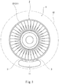
Fig. 1 is a front view of an aircraft engine to which mount mechanisms of an accessory gear box according to one embodiment of the present invention are applied. -
Fig. 2 is a side view of the aircraft engine ofFig. 1 . -
Fig. 3 is a side view of an aircraft engine according to a modified example. -
Fig. 4 is a front view of the mount mechanism. -
Fig. 5 is a cross-sectional view taken along line V-V ofFig. 4 -
Fig. 6 is an exploded perspective view of a pair of first brackets and a link. -
Figs. 1 and2 show anaircraft engine 1 to whichmount mechanisms 3 of an accessory gear box according to one embodiment of the present invention are applied. Theaircraft engine 1 is accommodated in a nacelle (cowling) 10. Theaircraft engine 1 includes anengine core 2 and anaccessory gear box 11. - The
engine core 2 includes anengine case 21 accommodating a rotary assembly. As shown inFig. 2 , theengine case 21 includes afan case 22, acompressor case 23, acombustion chamber case 24, and aturbine case 25. - The
accessory gear box 11 extends in the circumferential direction of theengine case 21. Theaccessory gear box 11 is mounted on theengine case 21 of theengine core 2 by the pair ofmount mechanisms 3 disposed at both end portions of theaccessory gear box 11. In the present embodiment, theaccessory gear box 11 is mounted on thefan case 22. Alternatively, as shown inFig. 3 , theaccessory gear box 11 may be mounted on thecompressor case 23. A plurality ofauxiliary devices 12 are mounted on theaccessory gearbox 11. - Next, each of the
mount mechanisms 3 will be described in detail with reference toFigs. 4 to 6 . Note that theaccessory gear box 11 may be mounted on thecompressor case 23 as described above. Therefore, in that case, the fan case 22 (described later) may be replaced by thecompressor case 23, as a matter of course. - Each of the
mount mechanisms 3 incudes a pair offirst brackets 4 fastened to thefan case 22, and asecond bracket 8 fastened to theaccessory gear box 11. Thefirst brackets 4 are fastened to thefan case 22 by, for example, fastening members (e.g., bolts) which are not shown. Alternatively, thefirst brackets 4 may be integrated with thefan case 22. In this case, each of thefirst brackets 4 may include only a pair of first lugs 41 (described later), without including lands 42 (described later). Thesecond bracket 8 is fastened to theaccessory gear box 11 in such a manner that thesecond bracket 8 is integrated with a housing of theaccessory gear box 11, for example. Alternatively, thesecond bracket 8 may be fastened to theaccessory gear box 11 by fastening members such as bolts. The pair offirst brackets 4 are connected to thesecond bracket 8 via alink 5. In the present embodiment, thelink 5 is a linear (straight-line) member with a constant width. - The pair of
first brackets 4 are apart from each other in the circumferential direction of thefan case 22. Each of the pair offirst brackets 4 includes the pair offirst lugs 41 between which the end portion of thelink 5 is interposed, and theland 42 with a plate shape which is in surface contact with thefan case 22. In other words, thelands 42 are bent to conform in shape to thefan case 22. - The
land 42 of each of the pair offirst brackets 4 has a U-shape in which theland 42 opens toward the other of the pair offirst brackets 4. In other words, each of thelands 42 includes a pair ofarm portions 42a which are parallel to each other on both sides of an opening of theland 42. The pair offirst lugs 41 protrude from thearm portions 42a, respectively. - A pair of
connectors 43 connect thearm portions 42a of theland 42 of one of the pair offirst brackets 4 to thearm portions 42a of theland 42 of the otherfirst bracket 4. In other words, the pair offirst brackets 4 and the pair ofconnectors 43 constitute a bracket unit having anelongated hole 45 in a center region. Theelongated hole 45 serves to avoid interference between the bracket unit and thelink 5. In this configuration, the size of each of themount mechanisms 3 in the radial direction of thefan case 22 can be reduced. Note that the configuration of each of themount mechanisms 3 may be suitably changed so that themount mechanism 3 is not formed with theelongated hole 45. Theconnectors 43 are plate-shaped members which have a thickness equal to that of thelands 42 and are bent to conform in shape to thefan case 22 for surface contact with thefan case 22. - The
link 5 extends in such a manner that the pair offirst brackets 4 are connected to each other via thelink 5. Thelink 5 may be bent to conform in shape to thefan case 22. The both end portions of thelink 5 are coupled to the pair offirst brackets 4 by a pair offirst pins 6, respectively. - In the present embodiment, as shown in
Fig. 5 , threerubber bushes 7 are penetrated by each of thefirst pins 6, as annular anti-vibration elements. Theserubber bushes 7 are retained by the pair offirst lugs 41 of each of thefirst brackets 4 and the end portion of thelink 5, respectively. - More specifically, the
first lugs 41 are provided with retainingholes 41a, respectively, in which therubber bushes 7 are accommodated, while the end portion of thelink 5 is provided with a retaininghole 51 in which therubber bush 7 is accommodated.Outer sleeves 65 are fitted to the retaining holes 41, 51a, respectively. In contrast, threeinner sleeves 63 are fitted to each of the first pins 6. Each of therubber bushes 7 is joined to corresponding one of theinner sleeves 63 and corresponding one of theouter sleeves 65, by, for example, an adhesive. - The material of the
rubber bushes 7 is not particularly limited. Various materials may be used as the material of therubber bushes 7. Each of therubber bushes 7 has a configuration in which a spring constant in the radial direction of thefirst pin 6 is higher than that in the axial direction of thefirst pin 6. Such anisotropy of the spring constant can be realized by, for example, orientation of an additive agent to be added in manufacturing of therubber bushes 7. The anisotropy of the spring constant makes it possible to adjust the spring constant and a damping rate into desired ones. - The spring constant of each of the
rubber bushes 7 in the radial direction of thefirst pin 6 has, for example, a non-linear characteristic in which the spring constant increases exponentially with respect to a distortion. - In the present embodiment, each of the
first pins 6 is a bolt including ashaft portion 61 formed with athread 61a in at least a tip end thereof, and ahead portion 62. Anut 64 is engaged with thethread 61a. Thenut 64 and thehead portion 62 serve to sandwich the threeinner sleeves 63 between them. Note that the configuration of each of thefirst pins 6 is not limited to this and can be suitably changed. - The
second bracket 8 is coupled to thelink 5 by a second pin 9, at a location between the pair offirst brackets 4. Thesecond bracket 8 includes a pair of second lugs 81 between which the center portion of thelink 5 is interposed. In the present embodiment, metal bushes 91 penetrated by the second pin 9 are retained by thesecond bracket 8 and thelink 5. Specifically, thesecond bracket 8 and thelink 5 are provided withfitting holes 82, 52, respectively to which the metal bushes 91 are fitted. - As should be appreciated from the above, in the
mount mechanisms 3 of the present embodiment, a load and a vibration which are transmitted from thefan case 22 to each of themount mechanism 3 is distributed to the pair offirst brackets 4 in a state in which a blade is disengaged. For this reason, therubber bushes 7 with a relatively small size can be used for the pair offirst pins 6 used to couple thefirst brackets 4 to the both end portions of thelink 5. This makes it possible to suppress a load and a vibration which are transmitted to theaccessory gear box 11 and reduce the size and weight of theaccessory gear box 11. - The pair of
first brackets 4 may be independent of each other. Nonetheless, in a case where the pair offirst brackets 4 and the pair ofconnectors 43 constitute the single bracket unit, the pair offirst brackets 4 can be handled as an integrated member. Since theelongated hole 45 is formed by the openings of thelands 42 and a gap between theconnectors 43, thelink 5 can be formed in a linear (straight-line) shape even when the bracket unit is bent to conform in shape to thefan case 22. Therefore, manufacturing cost of thelink 5 can be reduced. - In addition, in the present embodiment, the metal bushes 91 are retained by the
second bracket 8 and thelink 5, respectively. In this configuration, cost can be reduced, compared to a case where the rubber bushes 71 are also used for thesecond bracket 5. - Further, in the present embodiment, since the three
inner sleeves 63 are sandwiched between thehead portion 62 of the bolt which is thefirst pin 6, and thenut 64, each of themount mechanisms 3 can be easily assembled. - The present invention is not limited to the above-described embodiment, and can be modified in various ways within the scope of the invention.
- For example, each of the
first brackets 4 may not always include the pair offirst lugs 41, and may include only onefirst lug 41. In this case, each of the both end portions of thelink 5 may have two forked portions between which thefirst lug 41 is interposed. Or, in a case where thesecond bracket 8 includes only one second lug 81 in this configuration, thelink 5 may include two pieces between which thefirst lug 41 and the second lug 81 are interposed. Nonetheless, in a case where each of thefirst brackets 4 includes the pair offirst lugs 41 and thesecond bracket 8 includes the pair of second lugs 81 like the configuration of the present embodiment, thelink 5 can be configured as a single member with a simple shape. This can reduce cost. - In addition, the
rubber bushes 7 may not always be retained by the pair offirst lugs 41 and the end portion of thelink 5 so long as therubber bushes 7 are retained by at least one of each of thefirst brackets 4 and the end portion of the link 5 (at least either each of thefirst brackets 4 or the end portion of the link 5). In a case where therubber bushes 7 are retained by at least one of thefirst bracket 4 and the end portion of thelink 5 in this way, each of themount mechanisms 3 can be flexibly designed depending on a load and a vibration. - Further, the annular anti-vibration elements of the present embodiment are not limited to the
rubber bushes 7. For example, as the annular anti-vibration elements, members of a damper type which utilizes a liquid or metal-made springs may be used. - Although in the above-described embodiment, the
first brackets 4 are fastened to theengine case 21 and thesecond bracket 8 is fastened to theaccessory gear box 11, thefirst brackets 4 may be fastened to theaccessory gear box 11 and thesecond bracket 8 may be fastened to theengine case 21 in an alternative configuration. - Instead of the metal bushes 91, the
rubber bushes 7 may be retained by thesecond bracket 8 and the link, depending on a load and a vibration generated in a state in which the blade is disengaged (except a case where thefirst brackets 4 are fastened to theaccessory gear box 11 and thesecond bracket 8 is fastened to the engine case 21). -
- 1 aircraft engine
- 11 accessory gear box
- 21 engine case
- 3 mount mechanism
- 4 first bracket
- 41 first lug
- 41a retaining hole
- 42 land
- 42a arm portion
- 43 connector
- 5 link
- 51 retaining hole
- 6 first pin
- 61 shaft portion
- 61a thread
- 62 head portion
- 63 inner sleeve
- 64 nut
- 65 outer sleeve
- 7 rubber bush (anti-vibration element)
- 8 second bracket
- 81 second lug
- 9 second pin
- 91 metal bush
Claims (7)
- A mount mechanism used to mount an accessory gear box on an engine case in an aircraft engine, the mount mechanism of the accessory gear box comprising:a pair of first brackets fastened to one of the engine case and the accessory gear box, the pair of first brackets being apart from each other in a circumferential direction of the engine case;a link extending in such a manner that the pair of first brackets are connected to each other via the link, both end portions of the link being coupled to the pair of first brackets by a pair of first pins, respectively;an annular anti-vibration element penetrated by each of the pair of first pins, the annular anti-vibration element being retained by at least one of each of the pair of first brackets and the end portion of the link; anda second bracket fastened to the other of the engine case and the accessory gear box, the second bracket box being coupled to the link by a second pin at a location between the pair of first brackets.
- The mount mechanism of the accessory gear box according to claim 1,
wherein the annular anti-vibration element is a rubber bush, and
wherein the rubber bush has a configuration in which a spring constant in a radial direction of each of the pair of first pins is higher than a spring constant in an axial direction of each of the pair of first pins. - The mount mechanism of the accessory gear box according to claim 1 or 2,
wherein each of the pair of first brackets includes a pair of first lugs between which the end portion of the link is interposed, and
wherein the second bracket includes a pair of second lugs between which a center portion of the link is interposed. - The mount structure of the accessory gear box according to claim 3,
wherein the annular anti-vibration element is one of annular anti-vibration elements retained by the pair of first lugs and the end portion of the link, respectively, and
wherein each of the annular anti-vibration elements is joined to an inner sleeve fitted to each of the pair of first pins and to an outer sleeve fitted to a retaining hole provided in the first lugs or the link. - The mount structure of the accessory gear box according to claim 4,
wherein each of the first pins is a bolt including a shaft portion formed with a thread in at least a tip end thereof, and a head portion, and
wherein the inner sleeve is one of a plurality of inner sleeves, and a nut is engaged with the thread in such a manner that the plurality of inner sleeves are sandwiched between the nut and the head portion. - The mount mechanism of the accessory gear box according to any one of claims 3 to 5,
wherein each of the pair of first brackets includes a land with a U-shape in which the land opens toward the other of the pair of first brackets, and the pair of first lugs protrude from arm portions of the land which are parallel to each other, the mount mechanism of the accessory gear box further comprising:a pair of connectors that connect the arm portions of the land of one of the pair of first brackets to the arm portions of the land of the other of the pair of first brackets. - The mount mechanism of the accessory gear box according to any one of claims 1 to 6,
wherein a metal bush is penetrated by the second pin and retained by each of the second bracket and the link.
Applications Claiming Priority (1)
| Application Number | Priority Date | Filing Date | Title |
|---|---|---|---|
| PCT/JP2015/002350 WO2016181420A1 (en) | 2015-05-08 | 2015-05-08 | Mount mechanism for accessory gearbox |
Publications (3)
| Publication Number | Publication Date |
|---|---|
| EP3296215A1 true EP3296215A1 (en) | 2018-03-21 |
| EP3296215A4 EP3296215A4 (en) | 2018-10-03 |
| EP3296215B1 EP3296215B1 (en) | 2020-02-26 |
Family
ID=57247984
Family Applications (1)
| Application Number | Title | Priority Date | Filing Date |
|---|---|---|---|
| EP15891748.4A Active EP3296215B1 (en) | 2015-05-08 | 2015-05-08 | Mount mechanism for accessory gearbox |
Country Status (4)
| Country | Link |
|---|---|
| US (1) | US10266274B2 (en) |
| EP (1) | EP3296215B1 (en) |
| JP (1) | JP6564455B2 (en) |
| WO (1) | WO2016181420A1 (en) |
Cited By (2)
| Publication number | Priority date | Publication date | Assignee | Title |
|---|---|---|---|---|
| EP4403750A1 (en) * | 2023-01-20 | 2024-07-24 | Honeywell International Inc. | Mounting system for gearbox including corrugated bushing |
| US12116936B2 (en) | 2023-01-20 | 2024-10-15 | Honeywell International Inc. | Mounting system for gearbox including corrugated bushing |
Families Citing this family (8)
| Publication number | Priority date | Publication date | Assignee | Title |
|---|---|---|---|---|
| CN109027424A (en) * | 2017-06-12 | 2018-12-18 | 中国船舶重工集团公司第七研究院 | A Cylindrical Pipeline Vibration Isolator and Its Stiffness Calculation Method |
| US11261795B2 (en) * | 2018-10-18 | 2022-03-01 | Rolls-Royce North American Technologies, Inc. | Dual mode starter generator |
| US11008945B2 (en) * | 2018-10-18 | 2021-05-18 | Rolls-Royce North American Technologies, Inc. | Accessory gearbox with oppositely disposed starter/generator and air turbine starter |
| GB202307055D0 (en) * | 2023-05-12 | 2023-06-28 | Rolls Royce Plc | An accessory power module |
| FR3150505A1 (en) * | 2023-06-28 | 2025-01-03 | Airbus Operations | FRONT ENGINE MOUNTING SYSTEM FOR AN AIRCRAFT ENGINE HAVING A COMPACT STRUCTURE |
| CN117366205B (en) * | 2023-12-08 | 2024-02-20 | 南京传仕重工科技有限公司 | Gear box for cooling water tower |
| FR3162471B1 (en) * | 2024-05-21 | 2026-04-24 | Safran Aircraft Engines | Suspension of a turbomachine component to the turbomachine structure |
| CN121088782B (en) * | 2025-09-24 | 2026-05-01 | 陕西宏野联纵航天技术有限公司 | Vibration damping structure for aeroengine |
Family Cites Families (14)
| Publication number | Priority date | Publication date | Assignee | Title |
|---|---|---|---|---|
| US6260351B1 (en) * | 1998-12-10 | 2001-07-17 | United Technologies Corporation | Controlled spring rate gearbox mount |
| JP2002127996A (en) * | 2000-10-25 | 2002-05-09 | Ishikawajima Harima Heavy Ind Co Ltd | Gearbox support for aircraft engines |
| JP2007069820A (en) * | 2005-09-08 | 2007-03-22 | Sumitomo Metal Ind Ltd | Railcar bogie |
| FR2917711B1 (en) * | 2007-06-25 | 2010-01-15 | Snecma | SUSPENSION OF A TURBOMOTEUR TO THE STRUCTURE OF AN AIRCRAFT |
| FR2923542B1 (en) * | 2007-11-13 | 2014-02-07 | Snecma | CARTER FERRULE, CARTER PROVIDED WITH SUCH A BRACKET, DEVICE FOR FASTENING AN ACCESSORY HOUSING ON A SUCH CARTER AND TURBOMACHINE COMPRISING SUCH A CARTER |
| US8950702B2 (en) * | 2008-01-18 | 2015-02-10 | United Technologies Corporation | Pylon and engine mount configuration |
| GB0810585D0 (en) * | 2008-06-11 | 2008-07-16 | Rolls Royce Plc | Engine mounting arrangement |
| JP2012167714A (en) * | 2011-02-10 | 2012-09-06 | Toyo Tire & Rubber Co Ltd | Rotation transmission coupling |
| EP2522832B1 (en) * | 2011-05-09 | 2014-08-06 | United Technologies Corporation | Axial accessory gearbox |
| US8561501B2 (en) * | 2011-05-31 | 2013-10-22 | United Technologies Corporation | Gearbox mount bracket |
| US20130042630A1 (en) * | 2011-08-19 | 2013-02-21 | United Technologies Corporation | Gas turbine engine accessory mount |
| US9777639B2 (en) * | 2012-12-23 | 2017-10-03 | United Technologies Corporation | Turbine engine gearbox mount with multiple fuse joints |
| EP2964936A4 (en) * | 2013-03-08 | 2016-11-02 | United Technologies Corp | Gearbox mounting assembly |
| US9605562B2 (en) * | 2015-02-09 | 2017-03-28 | United Techologies Corporation | Turbomachine accessory gearbox alignment pin |
-
2015
- 2015-05-08 EP EP15891748.4A patent/EP3296215B1/en active Active
- 2015-05-08 US US15/572,337 patent/US10266274B2/en active Active
- 2015-05-08 JP JP2017517449A patent/JP6564455B2/en active Active
- 2015-05-08 WO PCT/JP2015/002350 patent/WO2016181420A1/en not_active Ceased
Cited By (2)
| Publication number | Priority date | Publication date | Assignee | Title |
|---|---|---|---|---|
| EP4403750A1 (en) * | 2023-01-20 | 2024-07-24 | Honeywell International Inc. | Mounting system for gearbox including corrugated bushing |
| US12116936B2 (en) | 2023-01-20 | 2024-10-15 | Honeywell International Inc. | Mounting system for gearbox including corrugated bushing |
Also Published As
| Publication number | Publication date |
|---|---|
| EP3296215B1 (en) | 2020-02-26 |
| JP6564455B2 (en) | 2019-08-21 |
| EP3296215A4 (en) | 2018-10-03 |
| WO2016181420A1 (en) | 2016-11-17 |
| JPWO2016181420A1 (en) | 2018-02-22 |
| US10266274B2 (en) | 2019-04-23 |
| US20180118357A1 (en) | 2018-05-03 |
Similar Documents
| Publication | Publication Date | Title |
|---|---|---|
| US10266274B2 (en) | Mount mechanism of accessory gearbox | |
| EP2559883B1 (en) | Gas turbine engine gearbox mount | |
| US10066552B2 (en) | One degree-of-constraint semi-fusible gearbox mounting link | |
| US6212974B1 (en) | Variable stiffness positioning link for a gearbox | |
| US9707838B2 (en) | Powertrain housing assembly | |
| KR101686206B1 (en) | Electric power steering apparatus for vehicle and method of assembling the same | |
| WO2009112777A3 (en) | Aircraft engine assembly comprising downwardly offset engine mounts on the fan casing | |
| US10926885B2 (en) | Hybrid motion mount system | |
| JPWO2019198393A1 (en) | Anti-vibration device for unmanned aerial vehicles | |
| EP2893172A1 (en) | Assembly for mounting a turbine engine to a pylon | |
| US8556577B2 (en) | Lube pump retention method | |
| US20070188026A1 (en) | Damping structure for a rotor assembly of a motor | |
| CN104852501B (en) | The shell structure of drive device | |
| US10132245B2 (en) | Fusible link with coulomb damping | |
| US10100914B2 (en) | Gear | |
| JP6581000B2 (en) | Transmission case | |
| EP3726064B1 (en) | Holding device and heat shield for a holding device | |
| EP2450592A2 (en) | Dampening device | |
| CN105508851B (en) | A kind of airborne equipment fixing mounting support | |
| JP6612077B2 (en) | Diaphragm coupling | |
| EP3103725A1 (en) | Aircraft with an auxiliary power unit attached to the aircraft fuselage by means of an attachment system | |
| KR20160025322A (en) | Common Use type Trailing Arm Bush Unit | |
| US20060183558A1 (en) | Driveshaft coupling | |
| EP3572252A1 (en) | Support beam | |
| KR102383478B1 (en) | Transmission mount |
Legal Events
| Date | Code | Title | Description |
|---|---|---|---|
| STAA | Information on the status of an ep patent application or granted ep patent |
Free format text: STATUS: THE INTERNATIONAL PUBLICATION HAS BEEN MADE |
|
| PUAI | Public reference made under article 153(3) epc to a published international application that has entered the european phase |
Free format text: ORIGINAL CODE: 0009012 |
|
| STAA | Information on the status of an ep patent application or granted ep patent |
Free format text: STATUS: REQUEST FOR EXAMINATION WAS MADE |
|
| 17P | Request for examination filed |
Effective date: 20171130 |
|
| AK | Designated contracting states |
Kind code of ref document: A1 Designated state(s): AL AT BE BG CH CY CZ DE DK EE ES FI FR GB GR HR HU IE IS IT LI LT LU LV MC MK MT NL NO PL PT RO RS SE SI SK SM TR |
|
| AX | Request for extension of the european patent |
Extension state: BA ME |
|
| DAV | Request for validation of the european patent (deleted) | ||
| DAX | Request for extension of the european patent (deleted) | ||
| A4 | Supplementary search report drawn up and despatched |
Effective date: 20180903 |
|
| RIC1 | Information provided on ipc code assigned before grant |
Ipc: B64D 41/00 20060101AFI20180828BHEP Ipc: B64D 27/26 20060101ALI20180828BHEP Ipc: F02C 7/32 20060101ALI20180828BHEP |
|
| GRAP | Despatch of communication of intention to grant a patent |
Free format text: ORIGINAL CODE: EPIDOSNIGR1 |
|
| STAA | Information on the status of an ep patent application or granted ep patent |
Free format text: STATUS: GRANT OF PATENT IS INTENDED |
|
| INTG | Intention to grant announced |
Effective date: 20190919 |
|
| GRAS | Grant fee paid |
Free format text: ORIGINAL CODE: EPIDOSNIGR3 |
|
| GRAA | (expected) grant |
Free format text: ORIGINAL CODE: 0009210 |
|
| STAA | Information on the status of an ep patent application or granted ep patent |
Free format text: STATUS: THE PATENT HAS BEEN GRANTED |
|
| AK | Designated contracting states |
Kind code of ref document: B1 Designated state(s): AL AT BE BG CH CY CZ DE DK EE ES FI FR GB GR HR HU IE IS IT LI LT LU LV MC MK MT NL NO PL PT RO RS SE SI SK SM TR |
|
| REG | Reference to a national code |
Ref country code: GB Ref legal event code: FG4D |
|
| REG | Reference to a national code |
Ref country code: CH Ref legal event code: EP |
|
| REG | Reference to a national code |
Ref country code: AT Ref legal event code: REF Ref document number: 1237345 Country of ref document: AT Kind code of ref document: T Effective date: 20200315 |
|
| REG | Reference to a national code |
Ref country code: IE Ref legal event code: FG4D |
|
| REG | Reference to a national code |
Ref country code: DE Ref legal event code: R096 Ref document number: 602015047968 Country of ref document: DE |
|
| PG25 | Lapsed in a contracting state [announced via postgrant information from national office to epo] |
Ref country code: NO Free format text: LAPSE BECAUSE OF FAILURE TO SUBMIT A TRANSLATION OF THE DESCRIPTION OR TO PAY THE FEE WITHIN THE PRESCRIBED TIME-LIMIT Effective date: 20200526 Ref country code: FI Free format text: LAPSE BECAUSE OF FAILURE TO SUBMIT A TRANSLATION OF THE DESCRIPTION OR TO PAY THE FEE WITHIN THE PRESCRIBED TIME-LIMIT Effective date: 20200226 Ref country code: RS Free format text: LAPSE BECAUSE OF FAILURE TO SUBMIT A TRANSLATION OF THE DESCRIPTION OR TO PAY THE FEE WITHIN THE PRESCRIBED TIME-LIMIT Effective date: 20200226 |
|
| REG | Reference to a national code |
Ref country code: NL Ref legal event code: MP Effective date: 20200226 |
|
| REG | Reference to a national code |
Ref country code: LT Ref legal event code: MG4D |
|
| PG25 | Lapsed in a contracting state [announced via postgrant information from national office to epo] |
Ref country code: BG Free format text: LAPSE BECAUSE OF FAILURE TO SUBMIT A TRANSLATION OF THE DESCRIPTION OR TO PAY THE FEE WITHIN THE PRESCRIBED TIME-LIMIT Effective date: 20200526 Ref country code: GR Free format text: LAPSE BECAUSE OF FAILURE TO SUBMIT A TRANSLATION OF THE DESCRIPTION OR TO PAY THE FEE WITHIN THE PRESCRIBED TIME-LIMIT Effective date: 20200527 Ref country code: LV Free format text: LAPSE BECAUSE OF FAILURE TO SUBMIT A TRANSLATION OF THE DESCRIPTION OR TO PAY THE FEE WITHIN THE PRESCRIBED TIME-LIMIT Effective date: 20200226 Ref country code: IS Free format text: LAPSE BECAUSE OF FAILURE TO SUBMIT A TRANSLATION OF THE DESCRIPTION OR TO PAY THE FEE WITHIN THE PRESCRIBED TIME-LIMIT Effective date: 20200626 Ref country code: SE Free format text: LAPSE BECAUSE OF FAILURE TO SUBMIT A TRANSLATION OF THE DESCRIPTION OR TO PAY THE FEE WITHIN THE PRESCRIBED TIME-LIMIT Effective date: 20200226 Ref country code: HR Free format text: LAPSE BECAUSE OF FAILURE TO SUBMIT A TRANSLATION OF THE DESCRIPTION OR TO PAY THE FEE WITHIN THE PRESCRIBED TIME-LIMIT Effective date: 20200226 |
|
| PG25 | Lapsed in a contracting state [announced via postgrant information from national office to epo] |
Ref country code: NL Free format text: LAPSE BECAUSE OF FAILURE TO SUBMIT A TRANSLATION OF THE DESCRIPTION OR TO PAY THE FEE WITHIN THE PRESCRIBED TIME-LIMIT Effective date: 20200226 |
|
| PG25 | Lapsed in a contracting state [announced via postgrant information from national office to epo] |
Ref country code: DK Free format text: LAPSE BECAUSE OF FAILURE TO SUBMIT A TRANSLATION OF THE DESCRIPTION OR TO PAY THE FEE WITHIN THE PRESCRIBED TIME-LIMIT Effective date: 20200226 Ref country code: LT Free format text: LAPSE BECAUSE OF FAILURE TO SUBMIT A TRANSLATION OF THE DESCRIPTION OR TO PAY THE FEE WITHIN THE PRESCRIBED TIME-LIMIT Effective date: 20200226 Ref country code: ES Free format text: LAPSE BECAUSE OF FAILURE TO SUBMIT A TRANSLATION OF THE DESCRIPTION OR TO PAY THE FEE WITHIN THE PRESCRIBED TIME-LIMIT Effective date: 20200226 Ref country code: PT Free format text: LAPSE BECAUSE OF FAILURE TO SUBMIT A TRANSLATION OF THE DESCRIPTION OR TO PAY THE FEE WITHIN THE PRESCRIBED TIME-LIMIT Effective date: 20200719 Ref country code: RO Free format text: LAPSE BECAUSE OF FAILURE TO SUBMIT A TRANSLATION OF THE DESCRIPTION OR TO PAY THE FEE WITHIN THE PRESCRIBED TIME-LIMIT Effective date: 20200226 Ref country code: SK Free format text: LAPSE BECAUSE OF FAILURE TO SUBMIT A TRANSLATION OF THE DESCRIPTION OR TO PAY THE FEE WITHIN THE PRESCRIBED TIME-LIMIT Effective date: 20200226 Ref country code: CZ Free format text: LAPSE BECAUSE OF FAILURE TO SUBMIT A TRANSLATION OF THE DESCRIPTION OR TO PAY THE FEE WITHIN THE PRESCRIBED TIME-LIMIT Effective date: 20200226 Ref country code: SM Free format text: LAPSE BECAUSE OF FAILURE TO SUBMIT A TRANSLATION OF THE DESCRIPTION OR TO PAY THE FEE WITHIN THE PRESCRIBED TIME-LIMIT Effective date: 20200226 Ref country code: EE Free format text: LAPSE BECAUSE OF FAILURE TO SUBMIT A TRANSLATION OF THE DESCRIPTION OR TO PAY THE FEE WITHIN THE PRESCRIBED TIME-LIMIT Effective date: 20200226 |
|
| REG | Reference to a national code |
Ref country code: AT Ref legal event code: MK05 Ref document number: 1237345 Country of ref document: AT Kind code of ref document: T Effective date: 20200226 |
|
| REG | Reference to a national code |
Ref country code: DE Ref legal event code: R097 Ref document number: 602015047968 Country of ref document: DE |
|
| PLBE | No opposition filed within time limit |
Free format text: ORIGINAL CODE: 0009261 |
|
| STAA | Information on the status of an ep patent application or granted ep patent |
Free format text: STATUS: NO OPPOSITION FILED WITHIN TIME LIMIT |
|
| PG25 | Lapsed in a contracting state [announced via postgrant information from national office to epo] |
Ref country code: LI Free format text: LAPSE BECAUSE OF NON-PAYMENT OF DUE FEES Effective date: 20200531 Ref country code: CH Free format text: LAPSE BECAUSE OF NON-PAYMENT OF DUE FEES Effective date: 20200531 Ref country code: MC Free format text: LAPSE BECAUSE OF FAILURE TO SUBMIT A TRANSLATION OF THE DESCRIPTION OR TO PAY THE FEE WITHIN THE PRESCRIBED TIME-LIMIT Effective date: 20200226 Ref country code: IT Free format text: LAPSE BECAUSE OF FAILURE TO SUBMIT A TRANSLATION OF THE DESCRIPTION OR TO PAY THE FEE WITHIN THE PRESCRIBED TIME-LIMIT Effective date: 20200226 Ref country code: AT Free format text: LAPSE BECAUSE OF FAILURE TO SUBMIT A TRANSLATION OF THE DESCRIPTION OR TO PAY THE FEE WITHIN THE PRESCRIBED TIME-LIMIT Effective date: 20200226 |
|
| 26N | No opposition filed |
Effective date: 20201127 |
|
| PG25 | Lapsed in a contracting state [announced via postgrant information from national office to epo] |
Ref country code: SI Free format text: LAPSE BECAUSE OF FAILURE TO SUBMIT A TRANSLATION OF THE DESCRIPTION OR TO PAY THE FEE WITHIN THE PRESCRIBED TIME-LIMIT Effective date: 20200226 Ref country code: PL Free format text: LAPSE BECAUSE OF FAILURE TO SUBMIT A TRANSLATION OF THE DESCRIPTION OR TO PAY THE FEE WITHIN THE PRESCRIBED TIME-LIMIT Effective date: 20200226 |
|
| REG | Reference to a national code |
Ref country code: BE Ref legal event code: MM Effective date: 20200531 |
|
| PG25 | Lapsed in a contracting state [announced via postgrant information from national office to epo] |
Ref country code: LU Free format text: LAPSE BECAUSE OF NON-PAYMENT OF DUE FEES Effective date: 20200508 |
|
| PG25 | Lapsed in a contracting state [announced via postgrant information from national office to epo] |
Ref country code: IE Free format text: LAPSE BECAUSE OF NON-PAYMENT OF DUE FEES Effective date: 20200508 |
|
| PG25 | Lapsed in a contracting state [announced via postgrant information from national office to epo] |
Ref country code: BE Free format text: LAPSE BECAUSE OF NON-PAYMENT OF DUE FEES Effective date: 20200531 |
|
| PG25 | Lapsed in a contracting state [announced via postgrant information from national office to epo] |
Ref country code: TR Free format text: LAPSE BECAUSE OF FAILURE TO SUBMIT A TRANSLATION OF THE DESCRIPTION OR TO PAY THE FEE WITHIN THE PRESCRIBED TIME-LIMIT Effective date: 20200226 Ref country code: MT Free format text: LAPSE BECAUSE OF FAILURE TO SUBMIT A TRANSLATION OF THE DESCRIPTION OR TO PAY THE FEE WITHIN THE PRESCRIBED TIME-LIMIT Effective date: 20200226 Ref country code: CY Free format text: LAPSE BECAUSE OF FAILURE TO SUBMIT A TRANSLATION OF THE DESCRIPTION OR TO PAY THE FEE WITHIN THE PRESCRIBED TIME-LIMIT Effective date: 20200226 |
|
| PG25 | Lapsed in a contracting state [announced via postgrant information from national office to epo] |
Ref country code: MK Free format text: LAPSE BECAUSE OF FAILURE TO SUBMIT A TRANSLATION OF THE DESCRIPTION OR TO PAY THE FEE WITHIN THE PRESCRIBED TIME-LIMIT Effective date: 20200226 Ref country code: AL Free format text: LAPSE BECAUSE OF FAILURE TO SUBMIT A TRANSLATION OF THE DESCRIPTION OR TO PAY THE FEE WITHIN THE PRESCRIBED TIME-LIMIT Effective date: 20200226 |
|
| PGFP | Annual fee paid to national office [announced via postgrant information from national office to epo] |
Ref country code: GB Payment date: 20260323 Year of fee payment: 12 |
|
| PGFP | Annual fee paid to national office [announced via postgrant information from national office to epo] |
Ref country code: DE Payment date: 20260402 Year of fee payment: 12 |
|
| PGFP | Annual fee paid to national office [announced via postgrant information from national office to epo] |
Ref country code: FR Payment date: 20260401 Year of fee payment: 12 |