EP3296169A1 - Manual brake release for a cleaning machine - Google Patents
Manual brake release for a cleaning machine Download PDFInfo
- Publication number
- EP3296169A1 EP3296169A1 EP17179347.4A EP17179347A EP3296169A1 EP 3296169 A1 EP3296169 A1 EP 3296169A1 EP 17179347 A EP17179347 A EP 17179347A EP 3296169 A1 EP3296169 A1 EP 3296169A1
- Authority
- EP
- European Patent Office
- Prior art keywords
- brake
- cleaning device
- key
- drive
- mobile cleaning
- Prior art date
- Legal status (The legal status is an assumption and is not a legal conclusion. Google has not performed a legal analysis and makes no representation as to the accuracy of the status listed.)
- Withdrawn
Links
Images


Classifications
-
- A—HUMAN NECESSITIES
- A47—FURNITURE; DOMESTIC ARTICLES OR APPLIANCES; COFFEE MILLS; SPICE MILLS; SUCTION CLEANERS IN GENERAL
- A47L—DOMESTIC WASHING OR CLEANING; SUCTION CLEANERS IN GENERAL
- A47L11/00—Machines for cleaning floors, carpets, furniture, walls, or wall coverings
- A47L11/40—Parts or details of machines not provided for in groups A47L11/02 - A47L11/38, or not restricted to one of these groups, e.g. handles, arrangements of switches, skirts, buffers, levers
- A47L11/4011—Regulation of the cleaning machine by electric means; Control systems and remote control systems therefor
-
- A—HUMAN NECESSITIES
- A47—FURNITURE; DOMESTIC ARTICLES OR APPLIANCES; COFFEE MILLS; SPICE MILLS; SUCTION CLEANERS IN GENERAL
- A47L—DOMESTIC WASHING OR CLEANING; SUCTION CLEANERS IN GENERAL
- A47L11/00—Machines for cleaning floors, carpets, furniture, walls, or wall coverings
- A47L11/40—Parts or details of machines not provided for in groups A47L11/02 - A47L11/38, or not restricted to one of these groups, e.g. handles, arrangements of switches, skirts, buffers, levers
- A47L11/4091—Storing or parking devices, arrangements therefor; Means allowing transport of the machine when it is not being used
-
- B—PERFORMING OPERATIONS; TRANSPORTING
- B60—VEHICLES IN GENERAL
- B60T—VEHICLE BRAKE CONTROL SYSTEMS OR PARTS THEREOF; BRAKE CONTROL SYSTEMS OR PARTS THEREOF, IN GENERAL; ARRANGEMENT OF BRAKING ELEMENTS ON VEHICLES IN GENERAL; PORTABLE DEVICES FOR PREVENTING UNWANTED MOVEMENT OF VEHICLES; VEHICLE MODIFICATIONS TO FACILITATE COOLING OF BRAKES
- B60T17/00—Component parts, details, or accessories of power brake systems not covered by groups B60T8/00, B60T13/00 or B60T15/00, or presenting other characteristic features
- B60T17/18—Safety devices; Monitoring
-
- B—PERFORMING OPERATIONS; TRANSPORTING
- B60—VEHICLES IN GENERAL
- B60T—VEHICLE BRAKE CONTROL SYSTEMS OR PARTS THEREOF; BRAKE CONTROL SYSTEMS OR PARTS THEREOF, IN GENERAL; ARRANGEMENT OF BRAKING ELEMENTS ON VEHICLES IN GENERAL; PORTABLE DEVICES FOR PREVENTING UNWANTED MOVEMENT OF VEHICLES; VEHICLE MODIFICATIONS TO FACILITATE COOLING OF BRAKES
- B60T7/00—Brake-action initiating means
- B60T7/02—Brake-action initiating means for personal initiation
- B60T7/08—Brake-action initiating means for personal initiation hand actuated
-
- B—PERFORMING OPERATIONS; TRANSPORTING
- B60—VEHICLES IN GENERAL
- B60T—VEHICLE BRAKE CONTROL SYSTEMS OR PARTS THEREOF; BRAKE CONTROL SYSTEMS OR PARTS THEREOF, IN GENERAL; ARRANGEMENT OF BRAKING ELEMENTS ON VEHICLES IN GENERAL; PORTABLE DEVICES FOR PREVENTING UNWANTED MOVEMENT OF VEHICLES; VEHICLE MODIFICATIONS TO FACILITATE COOLING OF BRAKES
- B60T1/00—Arrangements of braking elements, i.e. of those parts where braking effect occurs specially for vehicles
- B60T1/005—Arrangements of braking elements, i.e. of those parts where braking effect occurs specially for vehicles by locking of wheel or transmission rotation
Definitions
- the invention relates to a mobile cleaning device, in particular floor cleaning machine, with a chassis, a drive, a battery and a self-locking brake, which acts on the drive or a drive axle.
- Such cleaning devices are powered by an electric motor and include an unlockable brake. To drive the cleaning device, it is necessary that the cleaning device is started with an ignition key. As a result, the brake is unlocked electromagnetically and controlled driving. When cleaning is complete, the cleaning device is switched off and the brake is automatically locked.
- the brake of the drive can be unlocked manually.
- the invention has for its object to provide a mobile cleaning device, in particular a floor cleaning machine, in which the operating safety is increased.
- the cleaning device comprises a key for putting an electric driving operation of the cleaning device and a Bremsentriegelungselement for manually unlocking a brake of the cleaning device, wherein the key and the brake release element are connected together as a manageable unit, so that by means of the key in a Ignition lock when switching on the vehicle operation, the brake can be unlocked and arranged the brake release element separately to the brake is.
- the brake with the brake release element can be unlocked and the key removed from the ignition.
- the key To start the driving operation, the key must be in the ignition. Since the key forms a unit with the brake release element and there is a physical separation between the ignition lock and the brake, it is not possible that the brake with the brake release element is unlocked and the drive can be started. The reliability is thus increased because the cleaning device can either be only in manual mode or only while driving.
- the key and the brake release element are preferably connected to a detachable connection element, in particular a ring.
- the ring can be made of spring steel or any other suitable material.
- the key and the brake release member are interconnected such that in normal use the key does not come off the brake release member.
- the key and the brake release member are in one piece. This allows the manufacture of the unit without costly assembly of the components.
- the key and the brake release element can also be permanently connected to each other. Nevertheless, these can be mutually movable.
- the key is connected to the brake release element to each other movable or flexible. As a result, a compact design can be created without the locking element protruding bulky on the key.
- a handle of the key may preferably be formed in one embodiment as a brake release element or as part of the brake release element. This also gives a simple structure.
- the brake comprises a locking element which locks the drive in a rest position. This prevents the cleaning device from unintentionally changing its position.
- the rest position is the state that occurs after the ignition is switched off.
- driving preferably carried out an electrically controlled unlocking the brake.
- the release of the brake is preferably done manually.
- the locking element is designed as an electromagnetic locking element. This represents a simple and small-sized embodiment.
- the drive is mechanically locked.
- the locking element preferably locks the drive in the rest position by means of a spring.
- the spring ensures that the locking element locks the drive latching as soon as the brake is no longer energized. As a result, the cleaning device is braked independently of a power supply.
- the locking element which is provided with the drive in a drive housing, is preferably transferred by a manual brake lock in an unlocked position, wherein the brake lock is arranged outside of the drive housing.
- the brake lock In situations where the battery is dead, in which may not be installed a battery or in which, for example, the cleaning device without electric drive must be pushed onto a trailer, the brake lock is thus accessible from the outside, without the time-consuming opening a housing. The operator can thus easily operate the brake lock to unlock the brake and manually move the cleaner.
- the brake release element in the unlocked position of the brake, the brake release element between the drive housing and the Brake lock positioned.
- the brake release member is slid between the drive housing and the brake lock.
- the locking element unlocks the drive.
- the spring acting on the locking element is tensioned.
- the tensioned spring additionally allows the brake release element between the drive housing and the brake lock to be preferably clamped in the unlocked position of the brake. As a result, the key with the brake release element can not fall out and lock the brake unintentionally.
- a preferred embodiment of the invention provides that the locking element of the brake is electromagnetically unlocked while driving. Once the ignition is turned off with the key, the electromagnetic field collapses and the spring causes the locking element to return to the locking position. As a result, great reliability is achieved and prevents accidental displacement of the cleaning device.
- a further preferred embodiment of the invention provides that one end of the brake release element, which lies opposite the connection to the key, is wedge-shaped. As a result, the brake release element can be pushed between the drive housing and the brake lock without great effort and without getting caught, even if these are hardly spaced apart from each other.
- the brake release element is made of plastic, but it can also be made of other sufficiently hard materials.
- FIG. 1 a schematic view of a cleaning device 10 is shown.
- This is, for example, a ride-floor cleaning machine, which comprises driven wheels 12, in particular a pair of wheels, and a steerable wheel 14 on a housing 17.
- the wheels 12 are driven by a drive 33 (FIG. FIG. 3 ), which is provided within a housing 17.
- a cleaning device 29 On a lower side of the cleaning device 10 is a cleaning device 29 through which a wet and / or dry cleaning of a floor is possible.
- the housing 17 further includes a seat 18 for an operator and a steering wheel 19 for driving the steerable wheel 14.
- a lateral to the seat 18 lying side member 11 includes a control panel 13, in which there is an ignition lock 20 and other controls.
- the cleaning device 10 In order to record the electrical operation of the cleaning device 10, the cleaning device 10 must be started with a key 21 inserted in the ignition lock 20. With the key 21, the cleaning device 10 can be turned on and off.
- FIG. 2 illustrated side member 11 includes a control panel 13, in which the ignition lock 20 is mounted. To put the cleaning device 10 in the driving operation, the key 21 is inserted into the ignition 20 and rotated. In the side member 11 is a battery 16, which supplies the drive 33 and the controls with power.
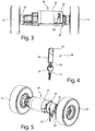
- FIG. 3 shows a side view of a drive axle 32 with the driven wheels 12, a fixed to the drive shaft 32 drive housing 31, in which the drive 33, in particular an electric motor, is arranged.
- the drive housing 31 comprises a brake 34 and a locking element 35, which can be arranged by a restoring element, in particular spring element in a locking position.
- the brake 34 is locked.
- the brake 34 is in particular an electromagnetic brake which is unlocked by current supply.
- driving the locking member 31 is electromagnetically transferred to an unlocked position and the brake 34 unlocked.
- the locking element 35 acting on the spring is tensioned. If the driving operation is interrupted or terminated, the electromagnetic field collapses and the spring pushes the locking element 35 into the locking position and the brake 34 locks the drive 33.
- a brake lock 30 On the outside of the drive housing 31 is a brake lock 30, which may be formed as a bracket. In FIG. 3 the brake lock is applied to the drive housing 31. In such a starting position, the brake 34 is locked. This brake lock 30 engages on the locking element 35 or can be converted by the brake lock 30, the locking element 35 in an unlocked position.
- a first embodiment of a handleable unit 26 consisting of a key 21 and a brake release member 23.
- the brake release element 23 is tapered wedge-shaped.
- the brake release element 23 is provided by means of a connecting element 22, which may be formed as a ring, movably connected to the key 21, preferably to a handle 25 of the key 21.
- the brake release element 23 is connected to the key 21 in such a way that it can not come loose from the key 21 during normal use.
- FIG. 5 shows a perspective view of the drive axle 32 from FIG. 3 .
- the brake release member 23, which is connected to the key 21 is pushed with the free end 24 between the brake lock 30 and the drive housing 31.
- the brake lock 30 is spaced from the drive housing 31.
- the locking element 35 is thereby forcibly transferred to the unlocking position and the brake 34 is unlocked.
- the brake 34 acts neither on the drive 33 nor on the drive shaft 32. In this state, the cleaning device 10 can be moved manually, for example pushed, become.
- FIG. 6 shows a side view and the FIG. 7 a top view of a further embodiment of the manageable unit 26.
- the key 21 and the brake release element 23 are integrally formed, wherein the handle 25 of the key 21 to the brake release element 23 is reorganized.
- the end 24 is also preferably tapered wedge-shaped here.
- FIG. 8 shows a further embodiment of the manageable unit 26.
- the entire handle 25 is wedge-shaped.
- the handle 25, which has been converted to the brake-unlocking element 23, can for example be attached to the key 21 or molded directly onto the key 21 during manufacture.
Abstract
Die Erfindung betrifft ein fahrbares Reinigungsgerät (10), insbesondere Boden-Reinigungsmaschine, mit einem Fahrgestell (15), einem Antrieb (33), einer Batterie (16) und einer selbstverriegelnden Bremse (34), die auf den Antrieb (33) oder eine Antriebsachse (32) wirkt, wobei ein Schlüssel (21) zur Inbetriebnahme eines elektrischen Fahrbetriebes des Reinigungsgerätes (10) und ein Bremsentriegelungselement (23) zur manuellen Entriegelung der Bremse (34) des Reinigungsgerätes (10) miteinander als eine handhabbare Einheit (26) verbunden sind, so dass mittels des Schlüssels (21) im Zündschloss (20) beim Einschalten des Fahrbetriebes die Bremse (34) entriegelbar ist und das Bremsentriegelungselement (23) getrennt zur Bremse (34) angeordnet ist oder in einem manuellen Betrieb die Bremse (34) mit dem Bremsentriegelungselement (23) entriegelbar ist und der Schlüssel (21) aus dem Zündschloss (20) abgezogen ist.

Description
Die Erfindung betrifft ein fahrbares Reinigungsgerät, insbesondere Boden-Reinigungsmaschine, mit einem Fahrgestell, einem Antrieb, einer Batterie und einer selbstverriegelnden Bremse, die auf den Antrieb oder eine Antriebsachse wirkt.The invention relates to a mobile cleaning device, in particular floor cleaning machine, with a chassis, a drive, a battery and a self-locking brake, which acts on the drive or a drive axle.
Solche Reinigungsgeräte werden durch einen Elektromotor angetrieben und umfassen eine entriegelbare Bremse. Zum Fahren des Reinigungsgerätes ist es erforderlich, dass das Reinigungsgerät mit einem Zündschlüssel gestartet wird. Dadurch wird die Bremse elektromagnetisch entriegelt und der Fahrbetrieb angesteuert. Nach Beendigung der Reinigung wird das Reinigungsgerät abgeschaltet und die Bremse automatisch verriegelt.Such cleaning devices are powered by an electric motor and include an unlockable brake. To drive the cleaning device, it is necessary that the cleaning device is started with an ignition key. As a result, the brake is unlocked electromagnetically and controlled driving. When cleaning is complete, the cleaning device is switched off and the brake is automatically locked.
Es treten Situationen ein, in denen die Batterie des Reinigungsgeräts leer ist, in denen keine Batterie eingebaut ist oder in denen beispielsweise das Reinigungsgerät ohne elektrischen Antrieb auf einen Anhänger für einen Transport geschoben werden muss.There are situations in which the battery of the cleaning device is empty, in which no battery is installed or in which, for example, the cleaning device without electric drive must be pushed onto a trailer for transport.
Um dies zu ermöglichen, kann die Bremse des Antriebs manuell entriegelt werden.To make this possible, the brake of the drive can be unlocked manually.
Allerdings kann der Fall eintreten, dass die Bedienperson nach dem Abschluss der manuellen Handhabung des Reinigungsgeräts vergisst, die manuelle Entriegelung der Bremse wieder rückgängig zu machen.However, the case may occur when the operator forgets to manually cancel the manual release of the brake after completing the manual handling of the cleaner.
Der Erfindung liegt die Aufgabe zugrunde, ein fahrbares Reinigungs-gerät, insbesondere eine Boden-Reinigungsmaschine bereitzustellen, bei dem die Bediensicherheit erhöht ist.The invention has for its object to provide a mobile cleaning device, in particular a floor cleaning machine, in which the operating safety is increased.
Zur Lösung dieser Aufgabe umfasst das Reinigungs-gerät einen Schlüssel zur Inbetriebnahme eines elektrischen Fahrbetriebes des Reinigungsgerätes und ein Bremsentriegelungselement zur manuellen Entriegelung einer Bremse des Reinigungsgerätes, wobei der Schlüssel und das Bremsentriegelungselement miteinander als eine handhabbare Einheit verbunden sind, so dass mittels des Schlüssels in einem Zündschloss beim Einschalten des Fahrbetriebes die Bremse entriegelbar ist und das Bremsentriegelungselement getrennt zur Bremse angeordnet ist. In einem manuellen Betrieb des Reinigungsgeräts ist die Bremse mit dem Bremsentriegelungselement entriegelbar und der Schlüssel aus dem Zündschloss abgezogen. Sobald die Bedienperson das Reinigungsgerät wieder motorgetrieben fortbewegen möchte, ist er gezwungen die manuelle Entriegelung wieder aufzuheben, da er den Schlüssel benötigt und somit zuvor das Bremsentriegelungselement von der Bremse abzieht. Gleiches gilt, wenn der manuelle Betrieb beendet wird, da die Bedienperson für den Schlüssel verantwortlich ist und diesen von dem Reinigungsgerät entfernt. Zum Starten des Fahrbetriebes muss sich der Schlüssel in dem Zündschloss befinden. Da der Schlüssel mit dem Bremsentriegelungselement eine Einheit bildet und eine räumliche Trennung zwischen Zündschloss und Bremse existiert, ist es nicht möglich, dass die Bremse mit dem Bremsentriegelungselement entriegelt ist und der Antrieb gestartet werden kann. Die Betriebssicherheit wird somit erhöht, da sich das Reinigungsgerät entweder nur im manuellen Betrieb oder nur im Fahrbetrieb befinden kann.To solve this problem, the cleaning device comprises a key for putting an electric driving operation of the cleaning device and a Bremsentriegelungselement for manually unlocking a brake of the cleaning device, wherein the key and the brake release element are connected together as a manageable unit, so that by means of the key in a Ignition lock when switching on the vehicle operation, the brake can be unlocked and arranged the brake release element separately to the brake is. In a manual operation of the cleaning device, the brake with the brake release element can be unlocked and the key removed from the ignition. As soon as the operator wants to move the cleaning device again motor-driven, he is forced to release the manual unlocking again, since he needs the key and thus previously deducts the brake release element of the brake. The same applies if the manual operation is terminated because the operator is responsible for the key and removes it from the cleaning device. To start the driving operation, the key must be in the ignition. Since the key forms a unit with the brake release element and there is a physical separation between the ignition lock and the brake, it is not possible that the brake with the brake release element is unlocked and the drive can be started. The reliability is thus increased because the cleaning device can either be only in manual mode or only while driving.
Bevorzugt sind der Schlüssel und das Bremsentriegelungselement mit einem lösbaren Verbindungselement, insbesondere einem Ring, verbunden. Der Ring kann aus Federstahl oder auch aus jedem anderen geeignetem Material bestehen. Der Schlüssel und das Bremsentriegelungselement sind derart miteinander verbunden, dass sich bei normalem Gebrauch der Schlüssel nicht von dem Bremsentriegelungselement löst.The key and the brake release element are preferably connected to a detachable connection element, in particular a ring. The ring can be made of spring steel or any other suitable material. The key and the brake release member are interconnected such that in normal use the key does not come off the brake release member.
In einer alternativen Ausführungsform sind der Schlüssel und das Bremsentriegelungselement einteilig. Dadurch kann die Herstellung der Einheit ohne kostspieliges Zusammensetzen der Komponenten erfolgen.In an alternative embodiment, the key and the brake release member are in one piece. This allows the manufacture of the unit without costly assembly of the components.
Alternativ können der Schlüssel und das Bremsentriegelungselement auch unlösbar miteinander verbunden sein. Dennoch können diese zueinander beweglich sein.Alternatively, the key and the brake release element can also be permanently connected to each other. Nevertheless, these can be mutually movable.
Des Weiteren ist bevorzugt, dass der Schlüssel mit dem Bremsentriegelungselement zueinander beweglich oder flexibel verbunden ist. Dadurch kann eine kompakte Bauform geschaffen werden ohne dass das Verriegelungselement sperrig am Schlüssel hervorsteht.Furthermore, it is preferred that the key is connected to the brake release element to each other movable or flexible. As a result, a compact design can be created without the locking element protruding bulky on the key.
Ein Griff des Schlüssels kann bevorzugt in einer Ausführungsform als Bremsentriegelungselement oder als Teil des Bremsentriegelungselements ausgebildet sein. Dadurch ist ebenfalls ein einfacher Aufbau gegeben.A handle of the key may preferably be formed in one embodiment as a brake release element or as part of the brake release element. This also gives a simple structure.
Vorzugsweise umfasst die Bremse ein Verriegelungselement, das in einer Ruheposition den Antrieb verriegelt. Dadurch wird verhindert, dass das Reinigungsgerät ungewollt seine Position verändert. Als Ruheposition wird der Zustand verstanden, der nach Ausschalten der Zündung eintritt. Im Fahrbetrieb hingegen erfolgt bevorzugt eine elektrisch angesteuerte Entriegelung der Bremse. Zum manuellen Fahrbetrieb erfolgt das Lösen der Bremse bevorzugt manuell.Preferably, the brake comprises a locking element which locks the drive in a rest position. This prevents the cleaning device from unintentionally changing its position. The rest position is the state that occurs after the ignition is switched off. When driving, however, preferably carried out an electrically controlled unlocking the brake. For manual driving, the release of the brake is preferably done manually.
Bevorzugt ist das Verriegelungselement als elektromagnetisches Verriegelungselement ausgebildet. Dies stellt eine einfache und kleinbauende Ausführungsform dar. Bevorzugt wird dabei der Antrieb mechanisch verriegelt.Preferably, the locking element is designed as an electromagnetic locking element. This represents a simple and small-sized embodiment. Preferably, the drive is mechanically locked.
Bevorzugt verriegelt mittels einer Feder das Verriegelungselement in der Ruheposition den Antrieb. Durch die Feder ist sichergestellt, dass das Verriegelungselement den Antrieb selbsthaltend verriegelt, sobald die Bremse nicht mehr bestromt wird. Dadurch wird unabhängig von einer Stromzufuhr das Reinigungsgerät gebremst.The locking element preferably locks the drive in the rest position by means of a spring. The spring ensures that the locking element locks the drive latching as soon as the brake is no longer energized. As a result, the cleaning device is braked independently of a power supply.
Das Verriegelungselement, welches mit dem Antrieb in einem Antriebsgehäuse vorgesehen ist, ist bevorzugt durch eine manuelle Bremsverriegelung in eine Entriegelungsposition überführbar, wobei die Bremsverriegelung außerhalb des Antriebsgehäuses angeordnet ist. In Situationen, in denen die Batterie leer ist, in denen möglicherweise keine Batterie eingebaut ist oder in denen beispielsweise das Reinigungsgerät ohne elektrischen Antrieb auf einen Anhänger geschoben werden muss, ist die Bremsverriegelung dadurch von außen zugänglich, ohne dass zeitaufwändig ein Gehäuse geöffnet werden muss. Die Bedienperson kann somit leicht die Bremsverriegelung betätigen, um die Bremse zu entriegeln und das Reinigungsgerät manuell fortbewegen.The locking element, which is provided with the drive in a drive housing, is preferably transferred by a manual brake lock in an unlocked position, wherein the brake lock is arranged outside of the drive housing. In situations where the battery is dead, in which may not be installed a battery or in which, for example, the cleaning device without electric drive must be pushed onto a trailer, the brake lock is thus accessible from the outside, without the time-consuming opening a housing. The operator can thus easily operate the brake lock to unlock the brake and manually move the cleaner.
Vorteilhafterweise ist in der Entriegelungsposition der Bremse das Bremsentriegelungselement zwischen dem Antriebsgehäuse und der Bremsverriegelung positioniert. Um die Bremse in die Entriegelungsposition zu überführen, wird das Bremsentriegelungselement zwischen das Antriebsgehäuse und die Bremsverriegelung geschoben. Dadurch entriegelt das Verriegelungselement den Antrieb. Gleichzeitig wird die auf das Verriegelungselement wirkende Feder gespannt.Advantageously, in the unlocked position of the brake, the brake release element between the drive housing and the Brake lock positioned. To transfer the brake to the unlocked position, the brake release member is slid between the drive housing and the brake lock. As a result, the locking element unlocks the drive. At the same time, the spring acting on the locking element is tensioned.
Die gespannte Feder ermöglicht zusätzlich, dass in der Entriegelungsposition der Bremse das Bremsentriegelungselement zwischen dem Antriebsgehäuse und der Bremsverriegelung vorzugsweise geklemmt gehalten ist. Dadurch kann der Schlüssel mit dem Bremsentriegelungselement nicht herausfallen und die Bremse ungewollt verriegeln.The tensioned spring additionally allows the brake release element between the drive housing and the brake lock to be preferably clamped in the unlocked position of the brake. As a result, the key with the brake release element can not fall out and lock the brake unintentionally.
Eine bevorzugte Ausgestaltung der Erfindung sieht vor, dass das Verriegelungselement der Bremse im Fahrbetrieb elektromagnetisch entriegelt ist. Sobald die Zündung mit dem Schlüssel abgeschaltet wird, fällt das elektromagnetische Feld zusammen und die Feder lässt das Verriegelungselement in die Verriegelungsposition zurückführen. Dadurch wird große Betriebssicherheit erreicht und ein ungewolltes Verschieben des Reinigungsgeräts verhindert.A preferred embodiment of the invention provides that the locking element of the brake is electromagnetically unlocked while driving. Once the ignition is turned off with the key, the electromagnetic field collapses and the spring causes the locking element to return to the locking position. As a result, great reliability is achieved and prevents accidental displacement of the cleaning device.
Eine weitere bevorzugte Ausgestaltung der Erfindung sieht vor, dass ein Ende des Bremsentriegelungselements, welches der Verbindung zum Schlüssel gegenüber liegt, keilförmig ausgebildet ist. Dadurch kann das Bremsentriegelungselement ohne große Kraftaufwendung und ohne sich zu verhaken zwischen das Antriebsgehäuse und die Bremsverriegelung geschoben werden, selbst wenn diese kaum voneinander beabstandet sind.A further preferred embodiment of the invention provides that one end of the brake release element, which lies opposite the connection to the key, is wedge-shaped. As a result, the brake release element can be pushed between the drive housing and the brake lock without great effort and without getting caught, even if these are hardly spaced apart from each other.
Bevorzugt ist das Bremsentriegelungselement aus Kunststoff hergestellt, es kann aber auch aus anderen ausreichend harten Materialien hergestellt sein.Preferably, the brake release element is made of plastic, but it can also be made of other sufficiently hard materials.
Die Erfindung sowie weitere vorteilhafte Ausführungsformen und Weiterbildungen derselben werden im Folgenden anhand der in den Zeichnungen dargestellten Beispiele näher beschrieben und erläutert. Die der Beschreibung und den Zeichnungen zu entnehmenden Merkmale können einzeln für sich oder zu mehreren in beliebiger Kombination erfindungsgemäß angewandt werden. Es zeigen:
-
Figur 1 eine schematische Seitenansicht eines Reinigungsgeräts, -
Figur 2 eine schematische, perspektivische Ansicht eines Seitenelements mit Bedienkonsole, -
Figur 3 eine schematische Ansicht einer Achse mit Antrieb, Bremse und Bremsverriegelung, -
Figur 4 eine Ausführungsform einer handhabbaren Einheit eines Schlüssels und eines Bremsverriegelungselements, -
Figur 5 eine schematische, perspektivische Ansicht der Achse inFigur 3 mit der Bremse im entriegelten Zustand, -
Figur 6 eine seitliche schematische Darstellung einer alternativen Ausführungsform der manuellen Einheit zuFigur 3 , -
Figur 7 eine Draufsicht auf die manuelle Einheit gemäßFigur 6 , und -
Figur 8 eine Draufsicht auf eine alternative Ausführungsform der manuellen Einheit zuFigur 6 .
-
FIG. 1 a schematic side view of a cleaning device, -
FIG. 2 a schematic, perspective view of a side element with control panel, -
FIG. 3 a schematic view of an axle with drive, brake and brake lock, -
FIG. 4 an embodiment of a handleable unit of a key and a brake locking element, -
FIG. 5 a schematic, perspective view of the axis inFIG. 3 with the brake in the unlocked state, -
FIG. 6 a schematic side view of an alternative embodiment of the manual unit toFIG. 3 . -
FIG. 7 a plan view of the manual unit according toFIG. 6 , and -
FIG. 8 a plan view of an alternative embodiment of the manual unit toFIG. 6 ,
In
Das in
Außenliegend am Antriebsgehäuse 31 befindet sich eine Bremsverriegelung 30, die als Bügel ausgebildet sein kann. In
In
Wird der manuelle Betrieb beendet oder möchte die Bedienperson wieder in den Fahrbetrieb wechseln, entfernt die Bedienperson das Bremsentriegelungselement 23, um den damit verbundenen Schlüssel 21 in das Zündschloss 20 zu stecken. Dies führt dazu, dass die Bremsverriegelung 30 zurückfedert und das Verriegelungselement 35 die Bremse 34 wieder verriegelt.If manual operation is terminated or if the operator wishes to switch back to driving, the operator removes the
Die
Die
Der zum Bremsentriegelungselement 23 umgebildete Griff 25 kann beispielsweise auf den Schlüssel 21 aufgesteckt sein oder bei der Herstellung direkt an den Schlüssel 21 angespritzt werden.The
Claims (13)
Applications Claiming Priority (1)
| Application Number | Priority Date | Filing Date | Title |
|---|---|---|---|
| DE202016104869.9U DE202016104869U1 (en) | 2016-09-05 | 2016-09-05 | Mobile cleaning device |
Publications (1)
| Publication Number | Publication Date |
|---|---|
| EP3296169A1 true EP3296169A1 (en) | 2018-03-21 |
Family
ID=59276599
Family Applications (1)
| Application Number | Title | Priority Date | Filing Date |
|---|---|---|---|
| EP17179347.4A Withdrawn EP3296169A1 (en) | 2016-09-05 | 2017-07-03 | Manual brake release for a cleaning machine |
Country Status (2)
| Country | Link |
|---|---|
| EP (1) | EP3296169A1 (en) |
| DE (1) | DE202016104869U1 (en) |
Citations (6)
| Publication number | Priority date | Publication date | Assignee | Title |
|---|---|---|---|---|
| US5623863A (en) * | 1995-12-29 | 1997-04-29 | Indian Head Industries, Inc. | Dual-thread release bolt for spring brake actuator |
| US5740887A (en) * | 1996-01-18 | 1998-04-21 | Jlg Industries, Inc. | Drive system for vertical mast personnel lift |
| JP3144702B2 (en) * | 1992-01-22 | 2001-03-12 | ヤマハ発動機株式会社 | Unmanned traveling vehicle |
| WO2003051707A2 (en) * | 2001-12-14 | 2003-06-26 | Hogesta Effi | Disk-brake lock for a motorcycle |
| EP2308730A1 (en) * | 2009-10-09 | 2011-04-13 | STILL GmbH | Control method for an electrically actuated parking brake of a mobile work device |
| US20160249779A1 (en) * | 2014-11-18 | 2016-09-01 | Nss Enterprises, Inc. | Floor cleaning or burnishing machine pivot suspension |
-
2016
- 2016-09-05 DE DE202016104869.9U patent/DE202016104869U1/en not_active Expired - Lifetime
-
2017
- 2017-07-03 EP EP17179347.4A patent/EP3296169A1/en not_active Withdrawn
Patent Citations (6)
| Publication number | Priority date | Publication date | Assignee | Title |
|---|---|---|---|---|
| JP3144702B2 (en) * | 1992-01-22 | 2001-03-12 | ヤマハ発動機株式会社 | Unmanned traveling vehicle |
| US5623863A (en) * | 1995-12-29 | 1997-04-29 | Indian Head Industries, Inc. | Dual-thread release bolt for spring brake actuator |
| US5740887A (en) * | 1996-01-18 | 1998-04-21 | Jlg Industries, Inc. | Drive system for vertical mast personnel lift |
| WO2003051707A2 (en) * | 2001-12-14 | 2003-06-26 | Hogesta Effi | Disk-brake lock for a motorcycle |
| EP2308730A1 (en) * | 2009-10-09 | 2011-04-13 | STILL GmbH | Control method for an electrically actuated parking brake of a mobile work device |
| US20160249779A1 (en) * | 2014-11-18 | 2016-09-01 | Nss Enterprises, Inc. | Floor cleaning or burnishing machine pivot suspension |
Also Published As
| Publication number | Publication date |
|---|---|
| DE202016104869U1 (en) | 2017-12-07 |
Similar Documents
| Publication | Publication Date | Title |
|---|---|---|
| EP0153663B1 (en) | Drive motor powered from an energy source for disc-like or wheeled engines with a control unit | |
| EP2710688B1 (en) | Electrical plug connector | |
| DE102010044138A1 (en) | Charging plug with lock detection | |
| DE102011116514A1 (en) | Charging port lock assembly for a vehicle | |
| DE102013112991A1 (en) | Charging plug for charging an electric vehicle | |
| DE19650751C1 (en) | Device for actuating at least one locking-clamp in vehicle steering system | |
| EP2669156B1 (en) | Trailer manoeuvring drive with coaxial arrangement of drive components | |
| DE3149071A1 (en) | "CENTRAL LOCKING WITH TWO DOOR CONTROL FOR VEHICLES" | |
| DE102011013957A1 (en) | Electrically assisted power steering with immobilizer | |
| DE2901429A1 (en) | DEVICE ON A VEHICLE ANTI-THEFT DEVICE | |
| EP1878416A2 (en) | Auxiliary drive device for manual wheelchairs | |
| WO2019166464A1 (en) | Gripper device for an object, charging robot having a gripper device | |
| DE112018004506T5 (en) | Connection locking actuator device for vehicle input connection | |
| DE102008037813A1 (en) | Vehicle e.g. car, has control and/or drive unit controlled by control element e.g. radiator mascot, which is arranged outside vehicle, and vehicle operating and controlling device operating and controlling vehicle | |
| DE102011078803A1 (en) | System for automated pulling up of mobile stretcher in ambulance, comprises linear guide, which is mounted to carrier accommodating platform in ambulance, where stretcher with folded chassis is manually slidable | |
| EP3821865A1 (en) | Castor swivel lock for electric wheelchair | |
| WO2014125065A1 (en) | Locking device for a plug-in connection | |
| EP3296169A1 (en) | Manual brake release for a cleaning machine | |
| WO2017211785A1 (en) | Handlebars with a base | |
| DE3440494A1 (en) | DEVICE FOR TRANSPORTING A UNIT LOAD | |
| DE2948390A1 (en) | Centralised lock system with motorised components - esp. for automobile, having cam switch controlling motor current circuit | |
| DE202014100202U1 (en) | Device for transporting container treatment units | |
| DE202009018844U1 (en) | Industrial transport vehicle | |
| DE19949408C1 (en) | Wheelchair drive wheel has a safety system where the electromotor cannot be operated until the drive wheel is locked properly in place | |
| DE10035261A1 (en) | Securing element for the positive locking of a rotor with a stator of a motor vehicle steering system |
Legal Events
| Date | Code | Title | Description |
|---|---|---|---|
| PUAI | Public reference made under article 153(3) epc to a published international application that has entered the european phase |
Free format text: ORIGINAL CODE: 0009012 |
|
| STAA | Information on the status of an ep patent application or granted ep patent |
Free format text: STATUS: THE APPLICATION HAS BEEN PUBLISHED |
|
| AK | Designated contracting states |
Kind code of ref document: A1 Designated state(s): AL AT BE BG CH CY CZ DE DK EE ES FI FR GB GR HR HU IE IS IT LI LT LU LV MC MK MT NL NO PL PT RO RS SE SI SK SM TR |
|
| AX | Request for extension of the european patent |
Extension state: BA ME |
|
| STAA | Information on the status of an ep patent application or granted ep patent |
Free format text: STATUS: THE APPLICATION IS DEEMED TO BE WITHDRAWN |
|
| 18D | Application deemed to be withdrawn |
Effective date: 20180922 |