EP3296140A1 - Battery access system and method - Google Patents
Battery access system and method Download PDFInfo
- Publication number
- EP3296140A1 EP3296140A1 EP16873198.2A EP16873198A EP3296140A1 EP 3296140 A1 EP3296140 A1 EP 3296140A1 EP 16873198 A EP16873198 A EP 16873198A EP 3296140 A1 EP3296140 A1 EP 3296140A1
- Authority
- EP
- European Patent Office
- Prior art keywords
- unit
- battery
- current
- resistor
- force
- Prior art date
- Legal status (The legal status is an assumption and is not a legal conclusion. Google has not performed a legal analysis and makes no representation as to the accuracy of the status listed.)
- Granted
Links
Images



Classifications
-
- B—PERFORMING OPERATIONS; TRANSPORTING
- B60—VEHICLES IN GENERAL
- B60L—PROPULSION OF ELECTRICALLY-PROPELLED VEHICLES; SUPPLYING ELECTRIC POWER FOR AUXILIARY EQUIPMENT OF ELECTRICALLY-PROPELLED VEHICLES; ELECTRODYNAMIC BRAKE SYSTEMS FOR VEHICLES IN GENERAL; MAGNETIC SUSPENSION OR LEVITATION FOR VEHICLES; MONITORING OPERATING VARIABLES OF ELECTRICALLY-PROPELLED VEHICLES; ELECTRIC SAFETY DEVICES FOR ELECTRICALLY-PROPELLED VEHICLES
- B60L3/00—Electric devices on electrically-propelled vehicles for safety purposes; Monitoring operating variables, e.g. speed, deceleration or energy consumption
- B60L3/04—Cutting off the power supply under fault conditions
-
- B—PERFORMING OPERATIONS; TRANSPORTING
- B60—VEHICLES IN GENERAL
- B60L—PROPULSION OF ELECTRICALLY-PROPELLED VEHICLES; SUPPLYING ELECTRIC POWER FOR AUXILIARY EQUIPMENT OF ELECTRICALLY-PROPELLED VEHICLES; ELECTRODYNAMIC BRAKE SYSTEMS FOR VEHICLES IN GENERAL; MAGNETIC SUSPENSION OR LEVITATION FOR VEHICLES; MONITORING OPERATING VARIABLES OF ELECTRICALLY-PROPELLED VEHICLES; ELECTRIC SAFETY DEVICES FOR ELECTRICALLY-PROPELLED VEHICLES
- B60L15/00—Methods, circuits, or devices for controlling the traction-motor speed of electrically-propelled vehicles
- B60L15/20—Methods, circuits, or devices for controlling the traction-motor speed of electrically-propelled vehicles for control of the vehicle or its driving motor to achieve a desired performance, e.g. speed, torque, programmed variation of speed
-
- B—PERFORMING OPERATIONS; TRANSPORTING
- B60—VEHICLES IN GENERAL
- B60L—PROPULSION OF ELECTRICALLY-PROPELLED VEHICLES; SUPPLYING ELECTRIC POWER FOR AUXILIARY EQUIPMENT OF ELECTRICALLY-PROPELLED VEHICLES; ELECTRODYNAMIC BRAKE SYSTEMS FOR VEHICLES IN GENERAL; MAGNETIC SUSPENSION OR LEVITATION FOR VEHICLES; MONITORING OPERATING VARIABLES OF ELECTRICALLY-PROPELLED VEHICLES; ELECTRIC SAFETY DEVICES FOR ELECTRICALLY-PROPELLED VEHICLES
- B60L15/00—Methods, circuits, or devices for controlling the traction-motor speed of electrically-propelled vehicles
- B60L15/20—Methods, circuits, or devices for controlling the traction-motor speed of electrically-propelled vehicles for control of the vehicle or its driving motor to achieve a desired performance, e.g. speed, torque, programmed variation of speed
- B60L15/22—Methods, circuits, or devices for controlling the traction-motor speed of electrically-propelled vehicles for control of the vehicle or its driving motor to achieve a desired performance, e.g. speed, torque, programmed variation of speed with sequential operation of interdependent switches, e.g. relays, contactors or program drum
-
- B—PERFORMING OPERATIONS; TRANSPORTING
- B60—VEHICLES IN GENERAL
- B60L—PROPULSION OF ELECTRICALLY-PROPELLED VEHICLES; SUPPLYING ELECTRIC POWER FOR AUXILIARY EQUIPMENT OF ELECTRICALLY-PROPELLED VEHICLES; ELECTRODYNAMIC BRAKE SYSTEMS FOR VEHICLES IN GENERAL; MAGNETIC SUSPENSION OR LEVITATION FOR VEHICLES; MONITORING OPERATING VARIABLES OF ELECTRICALLY-PROPELLED VEHICLES; ELECTRIC SAFETY DEVICES FOR ELECTRICALLY-PROPELLED VEHICLES
- B60L3/00—Electric devices on electrically-propelled vehicles for safety purposes; Monitoring operating variables, e.g. speed, deceleration or energy consumption
- B60L3/0023—Detecting, eliminating, remedying or compensating for drive train abnormalities, e.g. failures within the drive train
- B60L3/0046—Detecting, eliminating, remedying or compensating for drive train abnormalities, e.g. failures within the drive train relating to electric energy storage systems, e.g. batteries or capacitors
-
- B—PERFORMING OPERATIONS; TRANSPORTING
- B60—VEHICLES IN GENERAL
- B60L—PROPULSION OF ELECTRICALLY-PROPELLED VEHICLES; SUPPLYING ELECTRIC POWER FOR AUXILIARY EQUIPMENT OF ELECTRICALLY-PROPELLED VEHICLES; ELECTRODYNAMIC BRAKE SYSTEMS FOR VEHICLES IN GENERAL; MAGNETIC SUSPENSION OR LEVITATION FOR VEHICLES; MONITORING OPERATING VARIABLES OF ELECTRICALLY-PROPELLED VEHICLES; ELECTRIC SAFETY DEVICES FOR ELECTRICALLY-PROPELLED VEHICLES
- B60L50/00—Electric propulsion with power supplied within the vehicle
- B60L50/50—Electric propulsion with power supplied within the vehicle using propulsion power supplied by batteries or fuel cells
- B60L50/60—Electric propulsion with power supplied within the vehicle using propulsion power supplied by batteries or fuel cells using power supplied by batteries
-
- B—PERFORMING OPERATIONS; TRANSPORTING
- B60—VEHICLES IN GENERAL
- B60L—PROPULSION OF ELECTRICALLY-PROPELLED VEHICLES; SUPPLYING ELECTRIC POWER FOR AUXILIARY EQUIPMENT OF ELECTRICALLY-PROPELLED VEHICLES; ELECTRODYNAMIC BRAKE SYSTEMS FOR VEHICLES IN GENERAL; MAGNETIC SUSPENSION OR LEVITATION FOR VEHICLES; MONITORING OPERATING VARIABLES OF ELECTRICALLY-PROPELLED VEHICLES; ELECTRIC SAFETY DEVICES FOR ELECTRICALLY-PROPELLED VEHICLES
- B60L53/00—Methods of charging batteries, specially adapted for electric vehicles; Charging stations or on-board charging equipment therefor; Exchange of energy storage elements in electric vehicles
- B60L53/10—Methods of charging batteries, specially adapted for electric vehicles; Charging stations or on-board charging equipment therefor; Exchange of energy storage elements in electric vehicles characterised by the energy transfer between the charging station and the vehicle
-
- B—PERFORMING OPERATIONS; TRANSPORTING
- B60—VEHICLES IN GENERAL
- B60L—PROPULSION OF ELECTRICALLY-PROPELLED VEHICLES; SUPPLYING ELECTRIC POWER FOR AUXILIARY EQUIPMENT OF ELECTRICALLY-PROPELLED VEHICLES; ELECTRODYNAMIC BRAKE SYSTEMS FOR VEHICLES IN GENERAL; MAGNETIC SUSPENSION OR LEVITATION FOR VEHICLES; MONITORING OPERATING VARIABLES OF ELECTRICALLY-PROPELLED VEHICLES; ELECTRIC SAFETY DEVICES FOR ELECTRICALLY-PROPELLED VEHICLES
- B60L58/00—Methods or circuit arrangements for monitoring or controlling batteries or fuel cells, specially adapted for electric vehicles
- B60L58/10—Methods or circuit arrangements for monitoring or controlling batteries or fuel cells, specially adapted for electric vehicles for monitoring or controlling batteries
-
- B—PERFORMING OPERATIONS; TRANSPORTING
- B60—VEHICLES IN GENERAL
- B60L—PROPULSION OF ELECTRICALLY-PROPELLED VEHICLES; SUPPLYING ELECTRIC POWER FOR AUXILIARY EQUIPMENT OF ELECTRICALLY-PROPELLED VEHICLES; ELECTRODYNAMIC BRAKE SYSTEMS FOR VEHICLES IN GENERAL; MAGNETIC SUSPENSION OR LEVITATION FOR VEHICLES; MONITORING OPERATING VARIABLES OF ELECTRICALLY-PROPELLED VEHICLES; ELECTRIC SAFETY DEVICES FOR ELECTRICALLY-PROPELLED VEHICLES
- B60L58/00—Methods or circuit arrangements for monitoring or controlling batteries or fuel cells, specially adapted for electric vehicles
- B60L58/10—Methods or circuit arrangements for monitoring or controlling batteries or fuel cells, specially adapted for electric vehicles for monitoring or controlling batteries
- B60L58/12—Methods or circuit arrangements for monitoring or controlling batteries or fuel cells, specially adapted for electric vehicles for monitoring or controlling batteries responding to state of charge [SoC]
-
- B—PERFORMING OPERATIONS; TRANSPORTING
- B60—VEHICLES IN GENERAL
- B60L—PROPULSION OF ELECTRICALLY-PROPELLED VEHICLES; SUPPLYING ELECTRIC POWER FOR AUXILIARY EQUIPMENT OF ELECTRICALLY-PROPELLED VEHICLES; ELECTRODYNAMIC BRAKE SYSTEMS FOR VEHICLES IN GENERAL; MAGNETIC SUSPENSION OR LEVITATION FOR VEHICLES; MONITORING OPERATING VARIABLES OF ELECTRICALLY-PROPELLED VEHICLES; ELECTRIC SAFETY DEVICES FOR ELECTRICALLY-PROPELLED VEHICLES
- B60L58/00—Methods or circuit arrangements for monitoring or controlling batteries or fuel cells, specially adapted for electric vehicles
- B60L58/10—Methods or circuit arrangements for monitoring or controlling batteries or fuel cells, specially adapted for electric vehicles for monitoring or controlling batteries
- B60L58/16—Methods or circuit arrangements for monitoring or controlling batteries or fuel cells, specially adapted for electric vehicles for monitoring or controlling batteries responding to battery ageing, e.g. to the number of charging cycles or the state of health [SoH]
-
- H—ELECTRICITY
- H01—ELECTRIC ELEMENTS
- H01M—PROCESSES OR MEANS, e.g. BATTERIES, FOR THE DIRECT CONVERSION OF CHEMICAL ENERGY INTO ELECTRICAL ENERGY
- H01M50/00—Constructional details or processes of manufacture of the non-active parts of electrochemical cells other than fuel cells, e.g. hybrid cells
- H01M50/50—Current conducting connections for cells or batteries
- H01M50/572—Means for preventing undesired use or discharge
- H01M50/574—Devices or arrangements for the interruption of current
- H01M50/579—Devices or arrangements for the interruption of current in response to shock
-
- H—ELECTRICITY
- H02—GENERATION; CONVERSION OR DISTRIBUTION OF ELECTRIC POWER
- H02J—ELECTRIC POWER NETWORKS; CIRCUIT ARRANGEMENTS OR SYSTEMS FOR SUPPLYING OR DISTRIBUTING ELECTRIC POWER; SYSTEMS FOR STORING ELECTRIC ENERGY
- H02J7/00—Circuit arrangements for charging or discharging batteries or for supplying loads from batteries
-
- H—ELECTRICITY
- H02—GENERATION; CONVERSION OR DISTRIBUTION OF ELECTRIC POWER
- H02J—ELECTRIC POWER NETWORKS; CIRCUIT ARRANGEMENTS OR SYSTEMS FOR SUPPLYING OR DISTRIBUTING ELECTRIC POWER; SYSTEMS FOR STORING ELECTRIC ENERGY
- H02J7/00—Circuit arrangements for charging or discharging batteries or for supplying loads from batteries
- H02J7/14—Circuit arrangements for charging or discharging batteries or for supplying loads from batteries for charging batteries from dynamo-electric generators driven at varying speed, e.g. on vehicle
- H02J7/1423—Circuit arrangements for charging or discharging batteries or for supplying loads from batteries for charging batteries from dynamo-electric generators driven at varying speed, e.g. on vehicle with multiple batteries
-
- H—ELECTRICITY
- H02—GENERATION; CONVERSION OR DISTRIBUTION OF ELECTRIC POWER
- H02J—ELECTRIC POWER NETWORKS; CIRCUIT ARRANGEMENTS OR SYSTEMS FOR SUPPLYING OR DISTRIBUTING ELECTRIC POWER; SYSTEMS FOR STORING ELECTRIC ENERGY
- H02J7/00—Circuit arrangements for charging or discharging batteries or for supplying loads from batteries
- H02J7/14—Circuit arrangements for charging or discharging batteries or for supplying loads from batteries for charging batteries from dynamo-electric generators driven at varying speed, e.g. on vehicle
- H02J7/1446—Circuit arrangements for charging or discharging batteries or for supplying loads from batteries for charging batteries from dynamo-electric generators driven at varying speed, e.g. on vehicle in response to parameters of a vehicle
-
- H—ELECTRICITY
- H02—GENERATION; CONVERSION OR DISTRIBUTION OF ELECTRIC POWER
- H02J—ELECTRIC POWER NETWORKS; CIRCUIT ARRANGEMENTS OR SYSTEMS FOR SUPPLYING OR DISTRIBUTING ELECTRIC POWER; SYSTEMS FOR STORING ELECTRIC ENERGY
- H02J7/00—Circuit arrangements for charging or discharging batteries or for supplying loads from batteries
- H02J7/60—Circuit arrangements for charging or discharging batteries or for supplying loads from batteries including safety or protection arrangements
- H02J7/62—Circuit arrangements for charging or discharging batteries or for supplying loads from batteries including safety or protection arrangements against overcurrent
-
- H—ELECTRICITY
- H02—GENERATION; CONVERSION OR DISTRIBUTION OF ELECTRIC POWER
- H02J—ELECTRIC POWER NETWORKS; CIRCUIT ARRANGEMENTS OR SYSTEMS FOR SUPPLYING OR DISTRIBUTING ELECTRIC POWER; SYSTEMS FOR STORING ELECTRIC ENERGY
- H02J7/00—Circuit arrangements for charging or discharging batteries or for supplying loads from batteries
- H02J7/80—Circuit arrangements for charging or discharging batteries or for supplying loads from batteries including monitoring or indicating arrangements
- H02J7/84—Control of state of health [SOH]
-
- H—ELECTRICITY
- H02—GENERATION; CONVERSION OR DISTRIBUTION OF ELECTRIC POWER
- H02J—ELECTRIC POWER NETWORKS; CIRCUIT ARRANGEMENTS OR SYSTEMS FOR SUPPLYING OR DISTRIBUTING ELECTRIC POWER; SYSTEMS FOR STORING ELECTRIC ENERGY
- H02J7/00—Circuit arrangements for charging or discharging batteries or for supplying loads from batteries
- H02J7/14—Circuit arrangements for charging or discharging batteries or for supplying loads from batteries for charging batteries from dynamo-electric generators driven at varying speed, e.g. on vehicle
- H02J7/143—Circuit arrangements for charging or discharging batteries or for supplying loads from batteries for charging batteries from dynamo-electric generators driven at varying speed, e.g. on vehicle with multiple generators
-
- H—ELECTRICITY
- H02—GENERATION; CONVERSION OR DISTRIBUTION OF ELECTRIC POWER
- H02J—ELECTRIC POWER NETWORKS; CIRCUIT ARRANGEMENTS OR SYSTEMS FOR SUPPLYING OR DISTRIBUTING ELECTRIC POWER; SYSTEMS FOR STORING ELECTRIC ENERGY
- H02J7/00—Circuit arrangements for charging or discharging batteries or for supplying loads from batteries
- H02J7/80—Circuit arrangements for charging or discharging batteries or for supplying loads from batteries including monitoring or indicating arrangements
- H02J7/82—Control of state of charge [SOC]
-
- Y—GENERAL TAGGING OF NEW TECHNOLOGICAL DEVELOPMENTS; GENERAL TAGGING OF CROSS-SECTIONAL TECHNOLOGIES SPANNING OVER SEVERAL SECTIONS OF THE IPC; TECHNICAL SUBJECTS COVERED BY FORMER USPC CROSS-REFERENCE ART COLLECTIONS [XRACs] AND DIGESTS
- Y02—TECHNOLOGIES OR APPLICATIONS FOR MITIGATION OR ADAPTATION AGAINST CLIMATE CHANGE
- Y02E—REDUCTION OF GREENHOUSE GAS [GHG] EMISSIONS, RELATED TO ENERGY GENERATION, TRANSMISSION OR DISTRIBUTION
- Y02E60/00—Enabling technologies; Technologies with a potential or indirect contribution to GHG emissions mitigation
- Y02E60/10—Energy storage using batteries
-
- Y—GENERAL TAGGING OF NEW TECHNOLOGICAL DEVELOPMENTS; GENERAL TAGGING OF CROSS-SECTIONAL TECHNOLOGIES SPANNING OVER SEVERAL SECTIONS OF THE IPC; TECHNICAL SUBJECTS COVERED BY FORMER USPC CROSS-REFERENCE ART COLLECTIONS [XRACs] AND DIGESTS
- Y02—TECHNOLOGIES OR APPLICATIONS FOR MITIGATION OR ADAPTATION AGAINST CLIMATE CHANGE
- Y02T—CLIMATE CHANGE MITIGATION TECHNOLOGIES RELATED TO TRANSPORTATION
- Y02T10/00—Road transport of goods or passengers
- Y02T10/60—Other road transportation technologies with climate change mitigation effect
- Y02T10/70—Energy storage systems for electromobility, e.g. batteries
-
- Y—GENERAL TAGGING OF NEW TECHNOLOGICAL DEVELOPMENTS; GENERAL TAGGING OF CROSS-SECTIONAL TECHNOLOGIES SPANNING OVER SEVERAL SECTIONS OF THE IPC; TECHNICAL SUBJECTS COVERED BY FORMER USPC CROSS-REFERENCE ART COLLECTIONS [XRACs] AND DIGESTS
- Y02—TECHNOLOGIES OR APPLICATIONS FOR MITIGATION OR ADAPTATION AGAINST CLIMATE CHANGE
- Y02T—CLIMATE CHANGE MITIGATION TECHNOLOGIES RELATED TO TRANSPORTATION
- Y02T10/00—Road transport of goods or passengers
- Y02T10/60—Other road transportation technologies with climate change mitigation effect
- Y02T10/7072—Electromobility specific charging systems or methods for batteries, ultracapacitors, supercapacitors or double-layer capacitors
-
- Y—GENERAL TAGGING OF NEW TECHNOLOGICAL DEVELOPMENTS; GENERAL TAGGING OF CROSS-SECTIONAL TECHNOLOGIES SPANNING OVER SEVERAL SECTIONS OF THE IPC; TECHNICAL SUBJECTS COVERED BY FORMER USPC CROSS-REFERENCE ART COLLECTIONS [XRACs] AND DIGESTS
- Y02—TECHNOLOGIES OR APPLICATIONS FOR MITIGATION OR ADAPTATION AGAINST CLIMATE CHANGE
- Y02T—CLIMATE CHANGE MITIGATION TECHNOLOGIES RELATED TO TRANSPORTATION
- Y02T10/00—Road transport of goods or passengers
- Y02T10/60—Other road transportation technologies with climate change mitigation effect
- Y02T10/72—Electric energy management in electromobility
-
- Y—GENERAL TAGGING OF NEW TECHNOLOGICAL DEVELOPMENTS; GENERAL TAGGING OF CROSS-SECTIONAL TECHNOLOGIES SPANNING OVER SEVERAL SECTIONS OF THE IPC; TECHNICAL SUBJECTS COVERED BY FORMER USPC CROSS-REFERENCE ART COLLECTIONS [XRACs] AND DIGESTS
- Y02—TECHNOLOGIES OR APPLICATIONS FOR MITIGATION OR ADAPTATION AGAINST CLIMATE CHANGE
- Y02T—CLIMATE CHANGE MITIGATION TECHNOLOGIES RELATED TO TRANSPORTATION
- Y02T10/00—Road transport of goods or passengers
- Y02T10/80—Technologies aiming to reduce greenhouse gasses emissions common to all road transportation technologies
- Y02T10/92—Energy efficient charging or discharging systems for batteries, ultracapacitors, supercapacitors or double-layer capacitors specially adapted for vehicles
-
- Y—GENERAL TAGGING OF NEW TECHNOLOGICAL DEVELOPMENTS; GENERAL TAGGING OF CROSS-SECTIONAL TECHNOLOGIES SPANNING OVER SEVERAL SECTIONS OF THE IPC; TECHNICAL SUBJECTS COVERED BY FORMER USPC CROSS-REFERENCE ART COLLECTIONS [XRACs] AND DIGESTS
- Y02—TECHNOLOGIES OR APPLICATIONS FOR MITIGATION OR ADAPTATION AGAINST CLIMATE CHANGE
- Y02T—CLIMATE CHANGE MITIGATION TECHNOLOGIES RELATED TO TRANSPORTATION
- Y02T90/00—Enabling technologies or technologies with a potential or indirect contribution to GHG emissions mitigation
- Y02T90/10—Technologies relating to charging of electric vehicles
- Y02T90/14—Plug-in electric vehicles
Definitions
- the present invention relates to a system and a method of connecting a battery, and a system and a method of connecting a battery, which include a relay unit connected to a battery by a current, and allow a current with a different intensity to flow in the relay unit according to whether force applied to a circuit from the outside is detected and a size of the detected force, thereby maintaining or blocking the connection of the relay unit to the battery in consideration of the detection of the force and the degree of danger of the detected force.
- a battery which is called a storage battery or a secondary battery, has a characteristic in an easy application according to a product group, excellent preservability, a high energy density, and the like.
- the battery attracts attention as an energy supply source for improving an environmentally-friendly characteristic and energy efficiency in that a by-product according to the use of energy is not generated, as well as a primary advantage in that it is possible to decrease the use of fossil fuel.
- the battery is universally applied to an electric vehicle, an energy storage system, an uninterruptible power supply system, and the like, as well as a portable device.
- the electric vehicle has a technical characteristic in that a power source for driving the vehicle is provided from electric energy stored in a battery, and because of this, the battery within the electric vehicle is considered as a core element influencing a determination on a travelling speed and a travelling distance, as well as a stable operation of the vehicle.
- an accident of disconnecting an electric circuit and the battery within the vehicle may be generated due to an impact, a vibration, and the like transferred to a vehicle body, which causes a sudden stop of the operation of the electric vehicle to lead to a secondary accident, and contains a risk in that an electrical short is generated from the battery, so that a body of a person in the vehicle may get an electric shock.
- the present invention is conceived to solve the aforementioned problem, and an object of the present invention is to provide a system and a method of connecting a battery, which detect force applied to a circuit from the outside and maintain or block a connection between a relay unit of the circuit and a battery in consideration of the degree of danger of the detected force.
- another object of the present invention is to provide a system and a method of connecting a battery, which minimize a current quantity for maintaining a connection between a relay unit of a circuit and a battery when force from the outside is not detected, thereby improving a residual capacity of the battery that is a current supply source.
- a system for connecting a battery includes: a relay unit connected to a battery by a current; a first resistor and a second resistor which are connected to the relay unit and are positioned in parallel; a first driving unit provided in a connection path of the relay unit and the first resistor and a second driving unit provided in a connection path of the relay unit and the second resistor; a detecting unit which detects force applied to a circuit from the outside; and a control unit which controls driving of the first driving unit and the second driving unit based on a result of the detection by the detecting unit.
- An entire resistance value by the first resistor and the second resistor may be determined according to whether the first driving unit and the second driving unit are driven, and an intensity of a current flowing in the relay unit may be different according to the entire resistance value, so that a connection of the relay unit to the battery may be maintained or blocked.
- the first resistor may have a larger resistance value than that of the second resistor.
- the first resistor may have a resistance value having a size corresponding to the current having the minimum intensity.
- control unit may drive only the first driving unit, so that the current having the minimum intensity may flow in the relay unit and the connection of the relay unit to the battery may be maintained by the current having the minimum intensity.
- the control unit may drive both the first driving unit and the second driving unit, so that a current larger than the current having the minimum intensity may flow in the relay unit by a parallel resistance value of the first resistor and the second resistor which are connected in parallel, and the connection of the relay unit to the battery may be maintained by the larger current than the current having the minimum intensity.
- the control unit may not drive both the first driving unit and the second driving unit, so that a current may not flow in the relay unit and the connection of the relay unit to the battery may be blocked.
- the relay unit may be an electromagnetic relay which is energized when a current flows and of which contact points are closed.
- the detecting unit may include one or more sensors for detecting the force.
- the force may correspond to one or more of vibration, pitching, and impact.
- a method of connecting a battery includes: serially connecting a first driving unit and a first resistor and serially connecting a second driving unit and a second resistor; positioning the serially connected first driving unit and first resistor and the serially connected second driving unit and second resistor in parallel to connect the resistors to a relay unit connected to a battery by a current; detecting force applied to a circuit from the outside; controlling driving of the first driving unit and the second driving unit based on a result of the detection in the detecting of the force; and determining an entire resistance value by the first resistor and the second resistor according to whether the first driving unit and the second driving unit are driven, and maintaining or blocking a connection of the relay unit to the battery based on a difference in an intensity of a current flowing in the relay unit according to the entire resistance value.
- the first resistor may have a larger resistance value than that of the second resistor.
- the first resistor may have a resistance value having a size corresponding to the current having the minimum intensity.
- the controlling may include driving only the first driving unit when the force is not detected in the detecting of the force.
- the maintaining or blocking of the connection of the relay unit to the battery may include making the current having the minimum intensity flow in the relay unit and maintaining the connection of the relay unit to the battery by the current having the minimum intensity.
- the controlling may further include, when the force is detected in the detecting of the force and the detected force is equal to or smaller than a predetermined reference value, driving both the first driving unit and the second driving unit.
- the maintaining or blocking of the connection of the relay unit to the battery may further include making a current larger than the current having the minimum intensity flow in the relay unit by a parallel resistance value of the first resistor and the second resistor which are connected in parallel, and maintaining the connection of the relay unit to the battery by the larger current than the current having the minimum intensity.
- the controlling may further include, when the force is detected in the detecting of the force and the detected force exceeds the predetermined reference value, not driving both the first driving unit and the second driving unit.
- the maintaining or blocking of the connection of the relay unit to the battery may further include making a current not flow in the relay unit and blocking the connection of the relay unit to the battery.
- the relay unit may be an electromagnetic relay which is energized when a current flows and of which contact points are closed.
- the detecting of the force may use one or more sensors for detecting the force.
- the force may correspond to one or more of vibration, pitching, and impact.
- ... unit described in the specification means a unit for processing one or more functions or operations and may be implemented by hardware or software and a combination of hardware and software.
- FIG. 1 is a diagram schematically illustrating an electric vehicle 1, to which a system and a method of connecting a battery according to an exemplary embodiment of the present invention are applicable.
- the system and the method of connecting the battery according to the exemplary embodiment of the present invention may be applied to various technical fields, to which a battery is applied and simultaneously, in which force, such as impact and vibration, may accompany in an operation or driving, as well as the electric vehicle 1.
- the electric vehicle 1 may include a battery 10, a battery management system (BMS) 20, an electronic control unit (ECU) 30, an inverter 40, and a motor 50.
- BMS battery management system
- ECU electronice control unit
- the battery 10 is an electric energy source providing driving force to the motor 50 and driving the electric vehicle 1, and may be charged or discharged by the inverter 40 according to the driving of the motor 50 and/or an internal combustion engine (not illustrated).
- the kind of battery 10 is not particularly limited, and examples of the battery 10 may include a lithium ion battery, a lithium polymer battery, a nickel cadmium battery, a nickel hydrogen battery, a nickel zinc battery, and the like.
- the BMS 20 may estimate state information, such as a state of charging (SOC), a state of health (SOH), the amount of maximum input/output allowance power, and an output voltage, of the battery 10 and control charging and discharging of the battery 10 by using the state information.
- state information such as a state of charging (SOC), a state of health (SOH), the amount of maximum input/output allowance power, and an output voltage
- the BMS 20 may include a battery connecting system 100 (see FIG. 2 ) according to the present invention, and may be connected with the battery 10 or a connection between the BMS 20 and the battery 10 may be blocked based on the driving of the battery connecting system.
- the ECU 30 is an electronic control apparatus controlling a state of the electric vehicle 1, and for example, the ECU 30 may determine the degree of torque based on information about an accelerator, a break, a speed, and the like, and control an output of the motor 50 to correspond to the torque information.
- the inverter 40 may receive a charging/discharging control signal of the battery 10 from the ECU 30 and make the battery 10 be charged or discharged based on the charging/discharging control signal of the ECU 30, and the motor 50 may drive the electric vehicle 1 based on electric energy of the battery 10 and the control information transmitted from the ECU 30.
- a current having a different potential difference from a micro-current to a high current may flow in the circuit, and in order to protect the constituent elements from the current, a circuit protecting device, such as a relay, needs to be provided within the circuit.
- the system and the method of connecting the battery according to the present invention aim to stably connect the circuit and the battery 10 through an appropriate connection of the relay to the battery 10, and particularly, aim to enable the battery 10 to be normally operated by appropriately maintaining the connection of the relay to the battery 10 from force, such as impact and vibration, transmitted to the electric vehicle, and protect the battery 10 by blocking the connection depending on a situation.
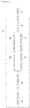
- FIG. 2 is a circuit diagram of a battery connecting system 100 according to an exemplary embodiment of the present invention.
- the battery connecting system 100 may include a relay unit 110, a detecting unit 120, a control unit 130, a first driving unit 140, a second driving unit 150, a first resistor 160, and a second resistor 170.
- the battery connecting system 100 illustrated in FIG. 2 is an exemplary embodiment, and it is noted that constituent elements thereof are not limited to the exemplary embodiment illustrated in FIG. 2 , and some constituent elements may be added, changed, or removed as necessary.
- the battery connecting system 100 may be implemented with the BMS 20 (see FIG. 1 ) itself, or may also be separately included in the BMS 20 (see FIG. 1 ).
- the relay unit 110 may be positioned at a distal end of a circuit, in which the constituent elements 120 to 170 are provided, and be connected to the battery 10 to serve to electrically connect the constituent elements 120 to 170 with the battery 10.
- the relay unit 110 may be implemented with an electromagnetic relay which has an energized characteristic when a current flows, and may include a solenoid 111, an iron piece 112, springs 113, and contact points 114 as the configuration.
- the solenoid 111 is not energized and does not exert magnetic force to the iron piece 112, and thus, the contact points 114 are not closed toward terminals connected with the battery 10.
- the electromagnetic relay implemented as the relay unit 110 may be formed in a temporary type in which opening/closing of the contact point 114 is immediately performed.
- the contact point 114 is operated according to the inflow of the current, so that the relay unit 110 may be connected to the battery 10 or the connection between the relay unit 110 and the battery 10 may be blocked, and in the exemplary embodiment, it is noted that the driving of the battery connecting system 100 according to the present invention is initiated in the state where the relay unit 110 is connected to the battery 10.
- the detecting unit 120 may serve to detect force applied to the circuit from the outside, and serve to provide a result of the detection to the control unit 130 which is to be described below.
- the force is a concept including vibration, pitching, impact, and the like
- the detecting unit 120 may include one or more of, for example, an impact detecting sensor, a vibration detecting sensor, and a motion detecting sensor detecting pitching of the circuit according to impact and vibration.
- the control unit 130 may determine whether force is applied based on the result of the detection provided from the detecting unit 120, compare detected force with a predetermined reference value when the force is detected, and determine whether the detected force exceeds the reference value. Further, the control unit 130 may control driving of the first driving unit 140 and the second driving unit 150 based on the determination.
- the first driving unit 140 and the second driving unit 150 may be implemented in a form of a switch, and the driving of the driving units 140 and 150 may mean the case where the driving units 140 and 150 are operated to be on to close the circuit. On the contrary, the circuit is opened when the driving units 140 and 150 are not driven.
- first driving unit 140 and the second driving unit 150 are positioned in parallel to be connected to the relay unit 110, and the first resistor 160 may be connected to the first driving unit 140 and the second resistor 170 may be connected to the second driving unit 150.
- first resistor 160 is serially connected to the first driving unit 140 and the second resistor 170 is serially connected to the second driving unit 150, and the first driving unit 140 and the first resistor 160, and the second driving unit 150 and the second resistor 170 may be positioned in parallel to be connected to the relay unit 110.
- control unit 130 may control only the first driving unit 140 to be driven.
- a path in the circuit, in which the first driving unit 140 is positioned, is closed, a path in the circuit, in which the second driving unit 150 is positioned, is opened, and an entire resistance value of the circuit may be determined by the first resistor 160.
- the first resistor 160 may be formed to have a larger resistance value than that of the second resistor 170. Further, in order to allow a current having a minimum intensity for maintaining the existing connection between the relay unit 110 and the battery 10, that is, a current having a minimum required intensity, by which the solenoid 111 (see FIG. 3 ) of the relay unit 110 is energized to make the contact point 114 (see FIG. 3 ) be closed to the terminals connected with the battery 10, to flow to the relay unit 110 when only the first driving unit 140 is driven, the resistance value of the first resistor 160 may be formed to have a size corresponding to the current.
- the connection of the relay unit 110 with the battery 10 may be maintained with the foregoing minimum intensity by the first resistor 160.
- control unit 130 may control both the first driving unit 140 and the second driving unit 150 to be driven.
- an entire resistance value of the circuit when both the first driving unit 140 and the second driving unit 150 are driven is smaller than an entire resistance value of the circuit when only the first driving unit 140 is driven, and this may mean that an intensity of a current flowing into the relay unit 110 when force is detected is larger than an intensity of a current flowing into the relay unit 110 when force is not detected.
- connection of the relay unit 110 to the battery 10 may be maintained with a larger current than the current having the foregoing minimum intensity by a parallel resistance value of the first resistor 160 and the second resistor 170.
- control unit 130 may control both the first driving unit 140 and the second driving unit 150 not to be driven.
- FIG. 4 is a flowchart for describing a battery connecting method according to an exemplary embodiment of the present invention.
- the detecting unit detects force applied to a circuit from the outside, and the control unit determines whether the force is detected based on a result of the detection (S410).
- the control unit drives only the first driving unit (S420), so that a path in the circuit, in which the first driving unit is positioned, is closed, and a path in the circuit, in which the second driving unit is positioned, is opened.
- an entire resistance value of the circuit is determined by the first resistor that is serially connected to the first driving unit (S421), and in this case, in order to allow a current having a minimum intensity for maintaining the connection of the relay unit to the battery to flow to the relay unit when only the first driving unit is driven, the first resistance value is set with a size corresponding to the current having the minimum intensity, so that the current having the minimum intensity flows in the relay unit (S422) and the existing connection of the battery is maintained (S423).
- control unit determines whether the detected force exceeds a predetermined reference value (S430).
- control unit controls both the first driving unit and the second driving unit to be driven (S431), and the paths in the circuit, in which the first driving unit and the second driving unit are positioned, respectively, are closed.
- an entire resistance value of the circuit is determined by the first resistor and the second resistor which are connected to each other in parallel (S432), and the entire resistance value of the circuit is smaller than an entire resistance value when only the first driving unit is driven by the parallel resistance value of the first resistor and the second resistor.
- control unit controls both the first driving unit and the second driving unit not to driven (S435).
Landscapes
- Engineering & Computer Science (AREA)
- Power Engineering (AREA)
- Transportation (AREA)
- Mechanical Engineering (AREA)
- Sustainable Development (AREA)
- Sustainable Energy (AREA)
- Life Sciences & Earth Sciences (AREA)
- Chemical & Material Sciences (AREA)
- Chemical Kinetics & Catalysis (AREA)
- Electrochemistry (AREA)
- General Chemical & Material Sciences (AREA)
- Charge And Discharge Circuits For Batteries Or The Like (AREA)
- Electric Propulsion And Braking For Vehicles (AREA)
Abstract
Description
- This application claims priority to and the benefit of Korean Patent Application No.
10-2015-0175773 - The present invention relates to a system and a method of connecting a battery, and a system and a method of connecting a battery, which include a relay unit connected to a battery by a current, and allow a current with a different intensity to flow in the relay unit according to whether force applied to a circuit from the outside is detected and a size of the detected force, thereby maintaining or blocking the connection of the relay unit to the battery in consideration of the detection of the force and the degree of danger of the detected force.
- A battery, which is called a storage battery or a secondary battery, has a characteristic in an easy application according to a product group, excellent preservability, a high energy density, and the like.
- Further, the battery attracts attention as an energy supply source for improving an environmentally-friendly characteristic and energy efficiency in that a by-product according to the use of energy is not generated, as well as a primary advantage in that it is possible to decrease the use of fossil fuel.
- Accordingly, the battery is universally applied to an electric vehicle, an energy storage system, an uninterruptible power supply system, and the like, as well as a portable device.
- Particularly, in the case of the electric vehicle industry, the battery is on the rise as an efficient alternative in an era in which a pollution problem become serious day by day and oil price is high, and in Korea, various businesses have been pushed forward to enter the four world powers in an electric vehicle field by the year of 2020.
- Unlike an existing vehicle which obtains driving energy by combusting fossil fuel, the electric vehicle has a technical characteristic in that a power source for driving the vehicle is provided from electric energy stored in a battery, and because of this, the battery within the electric vehicle is considered as a core element influencing a determination on a travelling speed and a travelling distance, as well as a stable operation of the vehicle.
- Accordingly, various devices and systems are developed for efficiently operating and appropriately protecting the battery of the electric vehicle, and for example, voltage balancing between cells of the battery, overcharging and overdischarging control, a detection of a swelling phenomenon, and an estimation of a residual capacity have been suggested.
- However, like the foregoing technologies, most of the related arts about the battery of the electric vehicle consider only a problem in an electric aspect, accidents that occur in the battery and the electric vehicle due to a physical factor are ignored.
- For example, when a minor accident is generated during an operation of the electric vehicle or the electric vehicle travels on the ground having severe unevenness, an accident of disconnecting an electric circuit and the battery within the vehicle may be generated due to an impact, a vibration, and the like transferred to a vehicle body, which causes a sudden stop of the operation of the electric vehicle to lead to a secondary accident, and contains a risk in that an electrical short is generated from the battery, so that a body of a person in the vehicle may get an electric shock.
- The present invention is conceived to solve the aforementioned problem, and an object of the present invention is to provide a system and a method of connecting a battery, which detect force applied to a circuit from the outside and maintain or block a connection between a relay unit of the circuit and a battery in consideration of the degree of danger of the detected force.
- In addition, another object of the present invention is to provide a system and a method of connecting a battery, which minimize a current quantity for maintaining a connection between a relay unit of a circuit and a battery when force from the outside is not detected, thereby improving a residual capacity of the battery that is a current supply source.
- A system for connecting a battery according to an exemplary embodiment of the present invention includes: a relay unit connected to a battery by a current; a first resistor and a second resistor which are connected to the relay unit and are positioned in parallel; a first driving unit provided in a connection path of the relay unit and the first resistor and a second driving unit provided in a connection path of the relay unit and the second resistor; a detecting unit which detects force applied to a circuit from the outside; and a control unit which controls driving of the first driving unit and the second driving unit based on a result of the detection by the detecting unit.
- An entire resistance value by the first resistor and the second resistor may be determined according to whether the first driving unit and the second driving unit are driven, and an intensity of a current flowing in the relay unit may be different according to the entire resistance value, so that a connection of the relay unit to the battery may be maintained or blocked.
- The first resistor may have a larger resistance value than that of the second resistor.
- In order to allow a current having a minimum intensity for maintaining the connection of the relay unit to the battery to flow in the relay unit when only the first driving unit is driven, the first resistor may have a resistance value having a size corresponding to the current having the minimum intensity.
- When the detecting unit does not detect the force, the control unit may drive only the first driving unit, so that the current having the minimum intensity may flow in the relay unit and the connection of the relay unit to the battery may be maintained by the current having the minimum intensity.
- When the detecting unit detects the force and the detected force is equal to or smaller than a predetermined reference value, the control unit may drive both the first driving unit and the second driving unit, so that a current larger than the current having the minimum intensity may flow in the relay unit by a parallel resistance value of the first resistor and the second resistor which are connected in parallel, and the connection of the relay unit to the battery may be maintained by the larger current than the current having the minimum intensity.
- When the detecting unit detects the force and the detected force exceeds the predetermined reference value, the control unit may not drive both the first driving unit and the second driving unit, so that a current may not flow in the relay unit and the connection of the relay unit to the battery may be blocked.
- The relay unit may be an electromagnetic relay which is energized when a current flows and of which contact points are closed.
- The detecting unit may include one or more sensors for detecting the force.
- The force may correspond to one or more of vibration, pitching, and impact.
- A method of connecting a battery according to an exemplary embodiment of the present invention includes: serially connecting a first driving unit and a first resistor and serially connecting a second driving unit and a second resistor; positioning the serially connected first driving unit and first resistor and the serially connected second driving unit and second resistor in parallel to connect the resistors to a relay unit connected to a battery by a current; detecting force applied to a circuit from the outside; controlling driving of the first driving unit and the second driving unit based on a result of the detection in the detecting of the force; and determining an entire resistance value by the first resistor and the second resistor according to whether the first driving unit and the second driving unit are driven, and maintaining or blocking a connection of the relay unit to the battery based on a difference in an intensity of a current flowing in the relay unit according to the entire resistance value.
- The first resistor may have a larger resistance value than that of the second resistor.
- In order to allow a current having a minimum intensity for maintaining the connection of the relay unit to the battery to flow in the relay unit when only the first driving unit is driven, the first resistor may have a resistance value having a size corresponding to the current having the minimum intensity.
- The controlling may include driving only the first driving unit when the force is not detected in the detecting of the force.
- The maintaining or blocking of the connection of the relay unit to the battery may include making the current having the minimum intensity flow in the relay unit and maintaining the connection of the relay unit to the battery by the current having the minimum intensity.
- The controlling may further include, when the force is detected in the detecting of the force and the detected force is equal to or smaller than a predetermined reference value, driving both the first driving unit and the second driving unit.
- The maintaining or blocking of the connection of the relay unit to the battery may further include making a current larger than the current having the minimum intensity flow in the relay unit by a parallel resistance value of the first resistor and the second resistor which are connected in parallel, and maintaining the connection of the relay unit to the battery by the larger current than the current having the minimum intensity.
- The controlling may further include, when the force is detected in the detecting of the force and the detected force exceeds the predetermined reference value, not driving both the first driving unit and the second driving unit.
- The maintaining or blocking of the connection of the relay unit to the battery may further include making a current not flow in the relay unit and blocking the connection of the relay unit to the battery.
- The relay unit may be an electromagnetic relay which is energized when a current flows and of which contact points are closed.
- The detecting of the force may use one or more sensors for detecting the force.
- The force may correspond to one or more of vibration, pitching, and impact.
- In the system and the method of connecting a battery according to the exemplary embodiment of the present invention, when force applied to a circuit from the outside is not detected, a connection between the relay unit and the battery is maintained by a current having a minimum intensity, thereby decreasing a discharged quantity of the battery that is a current supply source, and increasing an available residual capacity.
- In contrast to this, when force which is applied to the circuit from the outside and has a predetermined reference value or smaller is detected, a connection of the relay unit to the battery is maintained by a larger current than the current having the minimum intensity, so that it is possible to prevent the connection of the relay unit to the battery from being released due to slight vibration, pitching, impact, and the like, and when the force exceeding the reference value is detected, the connection of the relay unit to the battery is blocked, thereby protecting the battery from excessive vibration, pitching, impact, and the like.
-
-
FIG. 1 is a diagram schematically illustrating an electric vehicle, to which a system and a method of connecting a battery according to an exemplary embodiment of the present invention are applicable. -
FIG. 2 is a circuit diagram of a battery connecting system according to an exemplary embodiment of the present invention. -
FIG. 3 is a diagram schematically illustrating a characteristic of a relay unit that is a constituent element of the battery connecting system according to the exemplary embodiment of the present invention. -
FIG. 4 is a flowchart for describing a battery connecting method according to an exemplary embodiment of the present invention. - The present invention will be described in detail below with reference to the accompanying drawings. Herein, a repeated description, and the detailed description of a known function and configuration that may make the purpose of the present invention unnecessarily ambiguous will be omitted. Exemplary embodiments of the present invention are provided so as to more completely explain the present invention to those skilled in the art. Accordingly, the shape, the size, etc., of elements in the drawings may be exaggerated for a more clear description.
- Throughout the specification, unless explicitly described to the contrary, when it is said that a specific part "comprises" a specific constituent element, it means that other constituent elements may be further included, not that other constituent elements are excluded.
- In addition, the term "... unit" described in the specification means a unit for processing one or more functions or operations and may be implemented by hardware or software and a combination of hardware and software.
-
FIG. 1 is a diagram schematically illustrating anelectric vehicle 1, to which a system and a method of connecting a battery according to an exemplary embodiment of the present invention are applicable. - However, the system and the method of connecting the battery according to the exemplary embodiment of the present invention may be applied to various technical fields, to which a battery is applied and simultaneously, in which force, such as impact and vibration, may accompany in an operation or driving, as well as the
electric vehicle 1. - Referring to
FIG. 1 , theelectric vehicle 1 may include abattery 10, a battery management system (BMS) 20, an electronic control unit (ECU) 30, aninverter 40, and amotor 50. - The
battery 10 is an electric energy source providing driving force to themotor 50 and driving theelectric vehicle 1, and may be charged or discharged by theinverter 40 according to the driving of themotor 50 and/or an internal combustion engine (not illustrated). - Herein, the kind of
battery 10 is not particularly limited, and examples of thebattery 10 may include a lithium ion battery, a lithium polymer battery, a nickel cadmium battery, a nickel hydrogen battery, a nickel zinc battery, and the like. - For example, the
BMS 20 may estimate state information, such as a state of charging (SOC), a state of health (SOH), the amount of maximum input/output allowance power, and an output voltage, of thebattery 10 and control charging and discharging of thebattery 10 by using the state information. - Further, in the exemplary embodiment, the
BMS 20 may include a battery connecting system 100 (seeFIG. 2 ) according to the present invention, and may be connected with thebattery 10 or a connection between theBMS 20 and thebattery 10 may be blocked based on the driving of the battery connecting system. - The ECU 30 is an electronic control apparatus controlling a state of the
electric vehicle 1, and for example, theECU 30 may determine the degree of torque based on information about an accelerator, a break, a speed, and the like, and control an output of themotor 50 to correspond to the torque information. - The
inverter 40 may receive a charging/discharging control signal of thebattery 10 from theECU 30 and make thebattery 10 be charged or discharged based on the charging/discharging control signal of theECU 30, and themotor 50 may drive theelectric vehicle 1 based on electric energy of thebattery 10 and the control information transmitted from theECU 30. - As described above, in order to promote the
electric vehicle 1, driving force needs to be provided to wheels of the vehicle through an interconnecting operation of constituent elements, and to this end, the constituent elements need to be electrically connected through various circuits. - In this case, a current having a different potential difference from a micro-current to a high current may flow in the circuit, and in order to protect the constituent elements from the current, a circuit protecting device, such as a relay, needs to be provided within the circuit.
- The system and the method of connecting the battery according to the present invention aim to stably connect the circuit and the
battery 10 through an appropriate connection of the relay to thebattery 10, and particularly, aim to enable thebattery 10 to be normally operated by appropriately maintaining the connection of the relay to thebattery 10 from force, such as impact and vibration, transmitted to the electric vehicle, and protect thebattery 10 by blocking the connection depending on a situation. - Hereinafter, the system and the method of connecting the battery according to the present invention will be described with reference to
FIGS. 2 to 4 . -
FIG. 2 is a circuit diagram of abattery connecting system 100 according to an exemplary embodiment of the present invention. - Referring to
FIG. 2 , thebattery connecting system 100 according to the exemplary embodiment of the present invention may include arelay unit 110, a detectingunit 120, acontrol unit 130, afirst driving unit 140, asecond driving unit 150, afirst resistor 160, and asecond resistor 170. - However, the
battery connecting system 100 illustrated inFIG. 2 is an exemplary embodiment, and it is noted that constituent elements thereof are not limited to the exemplary embodiment illustrated inFIG. 2 , and some constituent elements may be added, changed, or removed as necessary. - Further, in the exemplary embodiment, it is noted that the
battery connecting system 100 may be implemented with the BMS 20 (seeFIG. 1 ) itself, or may also be separately included in the BMS 20 (seeFIG. 1 ). - First, the
relay unit 110 may be positioned at a distal end of a circuit, in which theconstituent elements 120 to 170 are provided, and be connected to thebattery 10 to serve to electrically connect theconstituent elements 120 to 170 with thebattery 10. - Herein, a configuration and a characteristic of the
relay unit 110 will be described with reference toFIG. 3 . Therelay unit 110 may be implemented with an electromagnetic relay which has an energized characteristic when a current flows, and may include asolenoid 111, aniron piece 112, springs 113, andcontact points 114 as the configuration. - Particularly, when a current does not flow into the
relay unit 110 as illustrated inFIG. 3A , thesolenoid 111 is not energized and does not exert magnetic force to theiron piece 112, and thus, the contact points 114 are not closed toward terminals connected with thebattery 10. - In the meantime, when a current flows into the
relay unit 110 as illustrated inFIG. 3B , thesolenoid 111 is energized by the current, and thesolenoid 111 is magnetized and theiron piece 112 moves down while compressing thesprints 113, so that the contact points 114 are closed toward the terminals connected with thebattery 10. - In this case, the electromagnetic relay implemented as the
relay unit 110 may be formed in a temporary type in which opening/closing of thecontact point 114 is immediately performed. - As described above, the
contact point 114 is operated according to the inflow of the current, so that therelay unit 110 may be connected to thebattery 10 or the connection between therelay unit 110 and thebattery 10 may be blocked, and in the exemplary embodiment, it is noted that the driving of thebattery connecting system 100 according to the present invention is initiated in the state where therelay unit 110 is connected to thebattery 10. - Referring back to
FIG. 2 , the detectingunit 120 may serve to detect force applied to the circuit from the outside, and serve to provide a result of the detection to thecontrol unit 130 which is to be described below. - Herein, the force is a concept including vibration, pitching, impact, and the like, and in order to detect the force, the detecting
unit 120 may include one or more of, for example, an impact detecting sensor, a vibration detecting sensor, and a motion detecting sensor detecting pitching of the circuit according to impact and vibration. - The
control unit 130 may determine whether force is applied based on the result of the detection provided from the detectingunit 120, compare detected force with a predetermined reference value when the force is detected, and determine whether the detected force exceeds the reference value. Further, thecontrol unit 130 may control driving of thefirst driving unit 140 and thesecond driving unit 150 based on the determination. - In the exemplary embodiment, the
first driving unit 140 and thesecond driving unit 150 may be implemented in a form of a switch, and the driving of the drivingunits units units - More particularly, the
first driving unit 140 and thesecond driving unit 150 are positioned in parallel to be connected to therelay unit 110, and thefirst resistor 160 may be connected to thefirst driving unit 140 and thesecond resistor 170 may be connected to thesecond driving unit 150. - That is, the
first resistor 160 is serially connected to thefirst driving unit 140 and thesecond resistor 170 is serially connected to thesecond driving unit 150, and thefirst driving unit 140 and thefirst resistor 160, and thesecond driving unit 150 and thesecond resistor 170 may be positioned in parallel to be connected to therelay unit 110. - In the meantime, when the detecting
unit 120 determines that the force is not detected, thecontrol unit 130 may control only thefirst driving unit 140 to be driven. - Accordingly, a path in the circuit, in which the
first driving unit 140 is positioned, is closed, a path in the circuit, in which thesecond driving unit 150 is positioned, is opened, and an entire resistance value of the circuit may be determined by thefirst resistor 160. - In this case, the
first resistor 160 may be formed to have a larger resistance value than that of thesecond resistor 170. Further, in order to allow a current having a minimum intensity for maintaining the existing connection between therelay unit 110 and thebattery 10, that is, a current having a minimum required intensity, by which the solenoid 111 (seeFIG. 3 ) of therelay unit 110 is energized to make the contact point 114 (seeFIG. 3 ) be closed to the terminals connected with thebattery 10, to flow to therelay unit 110 when only thefirst driving unit 140 is driven, the resistance value of thefirst resistor 160 may be formed to have a size corresponding to the current. - Accordingly, when only the
first driving unit 140 is driven, the connection of therelay unit 110 with thebattery 10 may be maintained with the foregoing minimum intensity by thefirst resistor 160. - In the meantime, when the detecting
unit 120 determines that the force is detected and the detected force is determined to be equal to or smaller than the predetermined reference value, thecontrol unit 130 may control both thefirst driving unit 140 and thesecond driving unit 150 to be driven. - In this case, all of the paths in the circuits, in which the
first driving unit 140 and thesecond driving unit 150 are positioned, respectively, are closed, and an entire resistance value of the circuit may be determined by thefirst resistor 160 and thesecond resistor 170. - In this case, the
first resistor 160 and thesecond resistor 170 are positioned in parallel, so that an entire resistance value of the circuit may be determined by an equation below which calculates an entire resistance value of the parallel circuit.
- Herein, RT is the entire resistors
- R1 is the first resistor
- R2 is the second resistor
- That is, an entire resistance value of the circuit when both the
first driving unit 140 and thesecond driving unit 150 are driven is smaller than an entire resistance value of the circuit when only thefirst driving unit 140 is driven, and this may mean that an intensity of a current flowing into therelay unit 110 when force is detected is larger than an intensity of a current flowing into therelay unit 110 when force is not detected. - Accordingly, when the force having the value that is equal to or smaller than the reference value is detected and both the
first driving unit 140 and thesecond driving unit 150 are driven, the connection of therelay unit 110 to thebattery 10 may be maintained with a larger current than the current having the foregoing minimum intensity by a parallel resistance value of thefirst resistor 160 and thesecond resistor 170. - Last, when the detecting
unit 120 determines that the force is detected and the detected force is determined to exceed the reference value, thecontrol unit 130 may control both thefirst driving unit 140 and thesecond driving unit 150 not to be driven. - In this case, all of the paths on the circuit, in which of the
first driving unit 140 and thesecond driving unit 150 are positioned, respectively, are opened, so that the current does not flow in therelay unit 110 and therelay unit 110 is not energized, so that the contact points 114 (seeFIG. 3 ) may be opened. - Accordingly, the existing connection of the
relay unit 110 to thebattery 10 is blocked, so that it is possible to prevent an abnormal problem of the circuit of thebattery 100 generable due to the force exceeding the reference value. -
FIG. 4 is a flowchart for describing a battery connecting method according to an exemplary embodiment of the present invention. - When the battery connecting method according to the exemplary embodiment of the present invention starts, the detecting unit detects force applied to a circuit from the outside, and the control unit determines whether the force is detected based on a result of the detection (S410).
- When it is determined that the force is not detected, the control unit drives only the first driving unit (S420), so that a path in the circuit, in which the first driving unit is positioned, is closed, and a path in the circuit, in which the second driving unit is positioned, is opened.
- Accordingly, an entire resistance value of the circuit is determined by the first resistor that is serially connected to the first driving unit (S421), and in this case, in order to allow a current having a minimum intensity for maintaining the connection of the relay unit to the battery to flow to the relay unit when only the first driving unit is driven, the first resistance value is set with a size corresponding to the current having the minimum intensity, so that the current having the minimum intensity flows in the relay unit (S422) and the existing connection of the battery is maintained (S423).
- In the meantime, when it is determined that the force is detected, the control unit determines whether the detected force exceeds a predetermined reference value (S430).
- When it is determined that the detected force is equal to or smaller than the reference value, the control unit controls both the first driving unit and the second driving unit to be driven (S431), and the paths in the circuit, in which the first driving unit and the second driving unit are positioned, respectively, are closed.
- In this case, an entire resistance value of the circuit is determined by the first resistor and the second resistor which are connected to each other in parallel (S432), and the entire resistance value of the circuit is smaller than an entire resistance value when only the first driving unit is driven by the parallel resistance value of the first resistor and the second resistor.
- Accordingly, a larger current than the current having the minimum intensity flows in the relay unit (S433), so that the existing connection of the relay unit to the battery is maintained from the force having the reference value or less (S434).
- When the detected force exceeds the reference value, the control unit controls both the first driving unit and the second driving unit not to driven (S435).
- Accordingly, all of the paths in the circuit, in which the first driving unit and the second driving unit are positioned, respectively, are opened, so that the current does not flow into the relay unit (S436).
- According to the characteristic of the relay unit which is energized by a current and is connected to the battery, when the current does not flow into the relay unit as described above, the existing connection with the battery is blocked (S437), so that an abnormal problem of the circuit of the battery generable from the force exceeding the reference value is prevented.
- In the forgoing, the specific exemplary embodiment of the present invention has been illustrated and described, but it is apparent to those skilled in the art that the technical spirit of the present invention is not limited by the accompanying drawings and the described contents, and may be modified in various forms without departing from the spirit of the present invention, and the modifications are considered to belong to the claims of the present invention without departing from the spirit of the present invention.
Claims (16)
- A system for connecting a battery, the system comprising:a relay unit connected to a battery by a current;a first resistor and a second resistor which are connected to the relay unit and are positioned in parallel;a first driving unit provided in a connection path of the relay unit and the first resistor and a second driving unit provided in a connection path of the relay unit and the second resistor;a detecting unit which detects force applied to a circuit from the outside; anda control unit which controls driving of the first driving unit and the second driving unit based on a result of the detection by the detecting unit,wherein an entire resistance value by the first resistor and the second resistor is determined according to whether the first driving unit and the second driving unit are driven, and an intensity of a current flowing in the relay unit is different according to the entire resistance value, so that a connection of the relay unit to the battery is maintained or blocked.
- The system of claim 1, wherein the first resistor has a larger resistance value than that of the second resistor, and
in order to allow a current having a minimum intensity for maintaining the connection of the relay unit to the battery to flow in the relay unit when only the first driving unit is driven, the first resistor has a resistance value having a size corresponding to the current having the minimum intensity. - The system of claim 2, wherein when the detecting unit does not detect the force, the control unit drives only the first driving unit, so that the current having the minimum intensity flows in the relay unit and the connection of the relay unit to the battery is maintained by the current having the minimum intensity.
- The system of claim 3, wherein when the detecting unit detects the force and the detected force is equal to or smaller than a predetermined reference value, the control unit drives both the first driving unit and the second driving unit, so that a current larger than the current having the minimum intensity flows in the relay unit by a parallel resistance value of the first resistor and the second resistor which are connected in parallel, and the connection of the relay unit to the battery is maintained by the larger current than the current having the minimum intensity.
- The system of claim 4, wherein when the detecting unit detects the force and the detected force exceeds the predetermined reference value, the control unit does not drive both the first driving unit and the second driving unit, so that a current does not flow in the relay unit and the connection of the relay unit to the battery is blocked.
- The system of claim 1, wherein the relay unit is an electromagnetic relay which is energized when a current flows and of which contact points are closed.
- The system of claim 1, wherein the detecting unit includes one or more sensors for detecting the force.
- The system of claim 1, wherein the force corresponds to one or more of vibration, pitching, and impact.
- A method of connecting a battery, the method comprising:serially connecting a first driving unit and a first resistor and serially connecting a second driving unit and a second resistor;positioning the serially connected first driving unit and first resistor and the serially connected second driving unit and second resistor in parallel to connect the resistors to a relay unit connected to a battery by a current;detecting force applied to a circuit from the outside;controlling driving of the first driving unit and the second driving unit based on a result of the detection in the detecting of the force; anddetermining an entire resistance value by the first resistor and the second resistor according to whether the first driving unit and the second driving unit are driven, and maintaining or blocking a connection of the relay unit to the battery based on a difference in an intensity of a current flowing in the relay unit according to the entire resistance value.
- The method of claim 9, wherein the first resistor has a larger resistance value than that of the second resistor, and
in order to allow a current having a minimum intensity for maintaining the connection of the relay unit to the battery to flow in the relay unit when only the first driving unit is driven, the first resistor has a resistance value having a size corresponding to the current having the minimum intensity. - The method of claim 10, wherein the controlling includes driving only the first driving unit when the force is not detected in the detecting of the force, and
the maintaining or blocking of the connection of the relay unit to the battery includes making the current having the minimum intensity flow in the relay unit and maintaining the connection of the relay unit to the battery by the current having the minimum intensity. - The method of claim 11, wherein the controlling further includes, when the force is detected in the detecting of the force and the detected force is equal to or smaller than a predetermined reference value, driving both the first driving unit and the second driving unit, and
the maintaining or blocking of the connection of the relay unit to the battery further includes making a current larger than the current having the minimum intensity flow in the relay unit by a parallel resistance value of the first resistor and the second resistor which are connected in parallel, and maintaining the connection of the relay unit to the battery by the larger current than the current having the minimum intensity. - The method of claim 12, wherein the controlling further includes, when the force is detected in the detecting of the force and the detected force exceeds the predetermined reference value, not driving both the first driving unit and the second driving unit, and
the maintaining or blocking of the connection of the relay unit to the battery further includes making a current not flow in the relay unit and blocking the connection of the relay unit to the battery. - The method of claim 9, wherein the relay unit is an electromagnetic relay which is energized when a current flows and of which contact points are closed.
- The method of claim 9, wherein the detecting of the force uses one or more sensors for detecting the force.
- The method of claim 9, wherein the force corresponds to one or more of vibration, pitching, and impact.
Priority Applications (1)
| Application Number | Priority Date | Filing Date | Title |
|---|---|---|---|
| PL16873198T PL3296140T3 (en) | 2015-12-10 | 2016-08-30 | MATERIAL FOR REPAIRING THE BLAST FURNACE |
Applications Claiming Priority (2)
| Application Number | Priority Date | Filing Date | Title |
|---|---|---|---|
| KR1020150175773A KR20170068826A (en) | 2015-12-10 | 2015-12-10 | System and method for connecting battery |
| PCT/KR2016/009624 WO2017099332A1 (en) | 2015-12-10 | 2016-08-30 | Battery access system and method |
Publications (3)
| Publication Number | Publication Date |
|---|---|
| EP3296140A1 true EP3296140A1 (en) | 2018-03-21 |
| EP3296140A4 EP3296140A4 (en) | 2018-10-03 |
| EP3296140B1 EP3296140B1 (en) | 2021-07-21 |
Family
ID=59013336
Family Applications (1)
| Application Number | Title | Priority Date | Filing Date |
|---|---|---|---|
| EP16873198.2A Active EP3296140B1 (en) | 2015-12-10 | 2016-08-30 | Battery access system and method |
Country Status (6)
| Country | Link |
|---|---|
| US (1) | US10266056B2 (en) |
| EP (1) | EP3296140B1 (en) |
| KR (1) | KR20170068826A (en) |
| CN (1) | CN107709081B (en) |
| PL (1) | PL3296140T3 (en) |
| WO (1) | WO2017099332A1 (en) |
Families Citing this family (1)
| Publication number | Priority date | Publication date | Assignee | Title |
|---|---|---|---|---|
| CN111591169B (en) * | 2020-05-29 | 2022-11-04 | 重庆长安新能源汽车科技有限公司 | Power battery high-voltage loop, control method and electric automobile |
Family Cites Families (17)
| Publication number | Priority date | Publication date | Assignee | Title |
|---|---|---|---|---|
| JP2002270075A (en) | 2001-03-07 | 2002-09-20 | Matsushita Electric Ind Co Ltd | Relay drive |
| JP2004007919A (en) | 2002-05-31 | 2004-01-08 | Fuji Heavy Ind Ltd | Battery circuit breaker for vehicle with high voltage battery |
| KR100758540B1 (en) | 2004-06-07 | 2007-09-14 | 주식회사 만도 | Solenoid valve drive |
| JP4513577B2 (en) * | 2005-01-17 | 2010-07-28 | トヨタ自動車株式会社 | Vehicle control device |
| JP2008199807A (en) | 2007-02-14 | 2008-08-28 | Toyota Motor Corp | Power supply circuit control device |
| JP5317188B2 (en) * | 2009-02-20 | 2013-10-16 | 株式会社安川電機 | Inverter device for electric vehicle and protection method thereof |
| KR101449083B1 (en) * | 2010-05-06 | 2014-10-13 | 엘에스산전 주식회사 | Switching Gate Drive |
| US8977416B2 (en) | 2010-07-09 | 2015-03-10 | Lg Electronics Inc. | Electric vehicle and method for controlling emergency thereof |
| KR20120012662A (en) | 2010-08-02 | 2012-02-10 | (주)브이이엔에스 | Electric Vehicles and Emergency Control Methods |
| KR101262524B1 (en) * | 2011-08-04 | 2013-05-08 | 주식회사 엘지화학 | Overcurrent protection apparatus for secondary bettery, protection method and battery pack |
| KR101353953B1 (en) * | 2012-02-20 | 2014-01-23 | 계명대학교 산학협력단 | A relay device and drive control method for power supply of electrical vehicle its |
| JP2014087081A (en) * | 2012-10-19 | 2014-05-12 | Toyota Motor Corp | Power storage system |
| JP2014207054A (en) * | 2013-04-10 | 2014-10-30 | トヨタ自動車株式会社 | Battery system |
| KR101644217B1 (en) * | 2013-07-02 | 2016-07-29 | 주식회사 엘지화학 | Apparatus and method for battery protection |
| CN203496695U (en) * | 2013-08-29 | 2014-03-26 | 海马商务汽车有限公司 | Automobile power supply control device and system |
| KR20150068845A (en) * | 2013-12-12 | 2015-06-22 | 현대자동차주식회사 | Battery assembly and hybrid vehicle comprsing the same |
| CN103802676B (en) * | 2014-02-18 | 2016-08-24 | 安徽江淮汽车股份有限公司 | A kind of car load power control system |
-
2015
- 2015-12-10 KR KR1020150175773A patent/KR20170068826A/en not_active Ceased
-
2016
- 2016-08-30 PL PL16873198T patent/PL3296140T3/en unknown
- 2016-08-30 WO PCT/KR2016/009624 patent/WO2017099332A1/en not_active Ceased
- 2016-08-30 US US15/576,957 patent/US10266056B2/en active Active
- 2016-08-30 CN CN201680034262.7A patent/CN107709081B/en active Active
- 2016-08-30 EP EP16873198.2A patent/EP3296140B1/en active Active
Also Published As
| Publication number | Publication date |
|---|---|
| WO2017099332A1 (en) | 2017-06-15 |
| US20180154795A1 (en) | 2018-06-07 |
| EP3296140B1 (en) | 2021-07-21 |
| CN107709081B (en) | 2020-06-02 |
| US10266056B2 (en) | 2019-04-23 |
| KR20170068826A (en) | 2017-06-20 |
| EP3296140A4 (en) | 2018-10-03 |
| PL3296140T3 (en) | 2021-12-27 |
| CN107709081A (en) | 2018-02-16 |
Similar Documents
| Publication | Publication Date | Title |
|---|---|---|
| JP5731543B2 (en) | Battery control apparatus and method | |
| KR101262524B1 (en) | Overcurrent protection apparatus for secondary bettery, protection method and battery pack | |
| CN106233562B (en) | System and method for equalizing charge of multiple energy storage modules | |
| KR101847685B1 (en) | Apparatus and Method for estimating state of battery | |
| EP3232502A1 (en) | System and method for sensing battery cell swelling | |
| KR20200041711A (en) | Apparatus and method for battery management | |
| CN102343831B (en) | System and method for rebalancing a vehicle battery | |
| KR20130049880A (en) | A battery pack and method for controlling the battery pack | |
| EP2869074A1 (en) | Device and method for calculating pre-charge resistance of battery pack | |
| CN106707146A (en) | Apparatus and method for detecting relay fusion of eco-friendly vehicle | |
| TW201240276A (en) | High voltage battery system for vehicle applications | |
| EP3240096A1 (en) | Battery pack protecting system and method | |
| KR101644217B1 (en) | Apparatus and method for battery protection | |
| CN110568366A (en) | An insulating circuit, battery pack leakage detection method and hardware detection method | |
| KR20150083739A (en) | Apparatus and method for preventing damage of precharge resistance and relay | |
| EP3296140B1 (en) | Battery access system and method | |
| KR20170097424A (en) | Contactor stuck-close detection system and method | |
| KR101712258B1 (en) | Apparatus and method for detecting welding of relay | |
| KR101602530B1 (en) | Battery pack leak diagnosis method and apparatus | |
| KR20180008215A (en) | Battery cell temperature control system and method | |
| JP6848775B2 (en) | Lithium ion secondary battery system | |
| EP3779482B1 (en) | Switch control apparatus and method | |
| JP4069720B2 (en) | Overcharge / discharge monitoring device for battery pack | |
| KR20140128626A (en) | Device for managing the battery of vehicle and method thereof | |
| EP4303600B1 (en) | Voltage determination circuit |
Legal Events
| Date | Code | Title | Description |
|---|---|---|---|
| STAA | Information on the status of an ep patent application or granted ep patent |
Free format text: STATUS: THE INTERNATIONAL PUBLICATION HAS BEEN MADE |
|
| PUAI | Public reference made under article 153(3) epc to a published international application that has entered the european phase |
Free format text: ORIGINAL CODE: 0009012 |
|
| STAA | Information on the status of an ep patent application or granted ep patent |
Free format text: STATUS: REQUEST FOR EXAMINATION WAS MADE |
|
| 17P | Request for examination filed |
Effective date: 20171212 |
|
| AK | Designated contracting states |
Kind code of ref document: A1 Designated state(s): AL AT BE BG CH CY CZ DE DK EE ES FI FR GB GR HR HU IE IS IT LI LT LU LV MC MK MT NL NO PL PT RO RS SE SI SK SM TR |
|
| AX | Request for extension of the european patent |
Extension state: BA ME |
|
| A4 | Supplementary search report drawn up and despatched |
Effective date: 20180904 |
|
| RIC1 | Information provided on ipc code assigned before grant |
Ipc: B60L 15/22 20060101ALI20180829BHEP Ipc: B60L 15/20 20060101ALI20180829BHEP Ipc: B60L 3/04 20060101AFI20180829BHEP Ipc: H01M 2/34 20060101ALI20180829BHEP Ipc: B60L 11/18 20060101ALI20180829BHEP |
|
| DAV | Request for validation of the european patent (deleted) | ||
| DAX | Request for extension of the european patent (deleted) | ||
| REG | Reference to a national code |
Ref country code: DE Ref legal event code: R079 Ref document number: 602016061101 Country of ref document: DE Free format text: PREVIOUS MAIN CLASS: B60L0003040000 Ipc: B60L0050500000 |
|
| GRAP | Despatch of communication of intention to grant a patent |
Free format text: ORIGINAL CODE: EPIDOSNIGR1 |
|
| STAA | Information on the status of an ep patent application or granted ep patent |
Free format text: STATUS: GRANT OF PATENT IS INTENDED |
|
| RIC1 | Information provided on ipc code assigned before grant |
Ipc: B60L 50/50 20190101AFI20210310BHEP |
|
| INTG | Intention to grant announced |
Effective date: 20210406 |
|
| GRAS | Grant fee paid |
Free format text: ORIGINAL CODE: EPIDOSNIGR3 |
|
| GRAA | (expected) grant |
Free format text: ORIGINAL CODE: 0009210 |
|
| STAA | Information on the status of an ep patent application or granted ep patent |
Free format text: STATUS: THE PATENT HAS BEEN GRANTED |
|
| AK | Designated contracting states |
Kind code of ref document: B1 Designated state(s): AL AT BE BG CH CY CZ DE DK EE ES FI FR GB GR HR HU IE IS IT LI LT LU LV MC MK MT NL NO PL PT RO RS SE SI SK SM TR |
|
| REG | Reference to a national code |
Ref country code: GB Ref legal event code: FG4D |
|
| REG | Reference to a national code |
Ref country code: CH Ref legal event code: EP |
|
| REG | Reference to a national code |
Ref country code: DE Ref legal event code: R096 Ref document number: 602016061101 Country of ref document: DE |
|
| REG | Reference to a national code |
Ref country code: AT Ref legal event code: REF Ref document number: 1412305 Country of ref document: AT Kind code of ref document: T Effective date: 20210815 |
|
| REG | Reference to a national code |
Ref country code: IE Ref legal event code: FG4D |
|
| REG | Reference to a national code |
Ref country code: SE Ref legal event code: TRGR |
|
| REG | Reference to a national code |
Ref country code: LT Ref legal event code: MG9D |
|
| REG | Reference to a national code |
Ref country code: NL Ref legal event code: MP Effective date: 20210721 |
|
| REG | Reference to a national code |
Ref country code: AT Ref legal event code: MK05 Ref document number: 1412305 Country of ref document: AT Kind code of ref document: T Effective date: 20210721 |
|
| RAP2 | Party data changed (patent owner data changed or rights of a patent transferred) |
Owner name: LG ENERGY SOLUTION LTD. |
|
| PG25 | Lapsed in a contracting state [announced via postgrant information from national office to epo] |
Ref country code: FI Free format text: LAPSE BECAUSE OF FAILURE TO SUBMIT A TRANSLATION OF THE DESCRIPTION OR TO PAY THE FEE WITHIN THE PRESCRIBED TIME-LIMIT Effective date: 20210721 Ref country code: ES Free format text: LAPSE BECAUSE OF FAILURE TO SUBMIT A TRANSLATION OF THE DESCRIPTION OR TO PAY THE FEE WITHIN THE PRESCRIBED TIME-LIMIT Effective date: 20210721 Ref country code: HR Free format text: LAPSE BECAUSE OF FAILURE TO SUBMIT A TRANSLATION OF THE DESCRIPTION OR TO PAY THE FEE WITHIN THE PRESCRIBED TIME-LIMIT Effective date: 20210721 Ref country code: PT Free format text: LAPSE BECAUSE OF FAILURE TO SUBMIT A TRANSLATION OF THE DESCRIPTION OR TO PAY THE FEE WITHIN THE PRESCRIBED TIME-LIMIT Effective date: 20211122 Ref country code: NL Free format text: LAPSE BECAUSE OF FAILURE TO SUBMIT A TRANSLATION OF THE DESCRIPTION OR TO PAY THE FEE WITHIN THE PRESCRIBED TIME-LIMIT Effective date: 20210721 Ref country code: NO Free format text: LAPSE BECAUSE OF FAILURE TO SUBMIT A TRANSLATION OF THE DESCRIPTION OR TO PAY THE FEE WITHIN THE PRESCRIBED TIME-LIMIT Effective date: 20211021 Ref country code: LT Free format text: LAPSE BECAUSE OF FAILURE TO SUBMIT A TRANSLATION OF THE DESCRIPTION OR TO PAY THE FEE WITHIN THE PRESCRIBED TIME-LIMIT Effective date: 20210721 Ref country code: AT Free format text: LAPSE BECAUSE OF FAILURE TO SUBMIT A TRANSLATION OF THE DESCRIPTION OR TO PAY THE FEE WITHIN THE PRESCRIBED TIME-LIMIT Effective date: 20210721 Ref country code: BG Free format text: LAPSE BECAUSE OF FAILURE TO SUBMIT A TRANSLATION OF THE DESCRIPTION OR TO PAY THE FEE WITHIN THE PRESCRIBED TIME-LIMIT Effective date: 20211021 Ref country code: RS Free format text: LAPSE BECAUSE OF FAILURE TO SUBMIT A TRANSLATION OF THE DESCRIPTION OR TO PAY THE FEE WITHIN THE PRESCRIBED TIME-LIMIT Effective date: 20210721 |
|
| PG25 | Lapsed in a contracting state [announced via postgrant information from national office to epo] |
Ref country code: LV Free format text: LAPSE BECAUSE OF FAILURE TO SUBMIT A TRANSLATION OF THE DESCRIPTION OR TO PAY THE FEE WITHIN THE PRESCRIBED TIME-LIMIT Effective date: 20210721 Ref country code: GR Free format text: LAPSE BECAUSE OF FAILURE TO SUBMIT A TRANSLATION OF THE DESCRIPTION OR TO PAY THE FEE WITHIN THE PRESCRIBED TIME-LIMIT Effective date: 20211022 |
|
| RAP4 | Party data changed (patent owner data changed or rights of a patent transferred) |
Owner name: LG ENERGY SOLUTION, LTD. |
|
| REG | Reference to a national code |
Ref country code: CH Ref legal event code: PL |
|
| REG | Reference to a national code |
Ref country code: DE Ref legal event code: R097 Ref document number: 602016061101 Country of ref document: DE Ref country code: BE Ref legal event code: MM Effective date: 20210831 |
|
| PG25 | Lapsed in a contracting state [announced via postgrant information from national office to epo] |
Ref country code: LI Free format text: LAPSE BECAUSE OF NON-PAYMENT OF DUE FEES Effective date: 20210831 Ref country code: DK Free format text: LAPSE BECAUSE OF FAILURE TO SUBMIT A TRANSLATION OF THE DESCRIPTION OR TO PAY THE FEE WITHIN THE PRESCRIBED TIME-LIMIT Effective date: 20210721 Ref country code: CH Free format text: LAPSE BECAUSE OF NON-PAYMENT OF DUE FEES Effective date: 20210831 |
|
| PLBE | No opposition filed within time limit |
Free format text: ORIGINAL CODE: 0009261 |
|
| STAA | Information on the status of an ep patent application or granted ep patent |
Free format text: STATUS: NO OPPOSITION FILED WITHIN TIME LIMIT |
|
| PG25 | Lapsed in a contracting state [announced via postgrant information from national office to epo] |
Ref country code: SM Free format text: LAPSE BECAUSE OF FAILURE TO SUBMIT A TRANSLATION OF THE DESCRIPTION OR TO PAY THE FEE WITHIN THE PRESCRIBED TIME-LIMIT Effective date: 20210721 Ref country code: SK Free format text: LAPSE BECAUSE OF FAILURE TO SUBMIT A TRANSLATION OF THE DESCRIPTION OR TO PAY THE FEE WITHIN THE PRESCRIBED TIME-LIMIT Effective date: 20210721 Ref country code: RO Free format text: LAPSE BECAUSE OF FAILURE TO SUBMIT A TRANSLATION OF THE DESCRIPTION OR TO PAY THE FEE WITHIN THE PRESCRIBED TIME-LIMIT Effective date: 20210721 Ref country code: MC Free format text: LAPSE BECAUSE OF FAILURE TO SUBMIT A TRANSLATION OF THE DESCRIPTION OR TO PAY THE FEE WITHIN THE PRESCRIBED TIME-LIMIT Effective date: 20210721 Ref country code: LU Free format text: LAPSE BECAUSE OF NON-PAYMENT OF DUE FEES Effective date: 20210830 Ref country code: EE Free format text: LAPSE BECAUSE OF FAILURE TO SUBMIT A TRANSLATION OF THE DESCRIPTION OR TO PAY THE FEE WITHIN THE PRESCRIBED TIME-LIMIT Effective date: 20210721 Ref country code: CZ Free format text: LAPSE BECAUSE OF FAILURE TO SUBMIT A TRANSLATION OF THE DESCRIPTION OR TO PAY THE FEE WITHIN THE PRESCRIBED TIME-LIMIT Effective date: 20210721 Ref country code: AL Free format text: LAPSE BECAUSE OF FAILURE TO SUBMIT A TRANSLATION OF THE DESCRIPTION OR TO PAY THE FEE WITHIN THE PRESCRIBED TIME-LIMIT Effective date: 20210721 |
|
| 26N | No opposition filed |
Effective date: 20220422 |
|
| PG25 | Lapsed in a contracting state [announced via postgrant information from national office to epo] |
Ref country code: IT Free format text: LAPSE BECAUSE OF FAILURE TO SUBMIT A TRANSLATION OF THE DESCRIPTION OR TO PAY THE FEE WITHIN THE PRESCRIBED TIME-LIMIT Effective date: 20210721 Ref country code: IE Free format text: LAPSE BECAUSE OF NON-PAYMENT OF DUE FEES Effective date: 20210830 Ref country code: BE Free format text: LAPSE BECAUSE OF NON-PAYMENT OF DUE FEES Effective date: 20210831 |
|
| REG | Reference to a national code |
Ref country code: DE Ref legal event code: R081 Ref document number: 602016061101 Country of ref document: DE Owner name: LG ENERGY SOLUTION, LTD., KR Free format text: FORMER OWNER: LG CHEM, LTD., SEOUL, KR |
|
| PG25 | Lapsed in a contracting state [announced via postgrant information from national office to epo] |
Ref country code: HU Free format text: LAPSE BECAUSE OF FAILURE TO SUBMIT A TRANSLATION OF THE DESCRIPTION OR TO PAY THE FEE WITHIN THE PRESCRIBED TIME-LIMIT; INVALID AB INITIO Effective date: 20160830 |
|
| P01 | Opt-out of the competence of the unified patent court (upc) registered |
Effective date: 20230512 |
|
| PG25 | Lapsed in a contracting state [announced via postgrant information from national office to epo] |
Ref country code: CY Free format text: LAPSE BECAUSE OF FAILURE TO SUBMIT A TRANSLATION OF THE DESCRIPTION OR TO PAY THE FEE WITHIN THE PRESCRIBED TIME-LIMIT Effective date: 20210721 |
|
| REG | Reference to a national code |
Ref country code: GB Ref legal event code: 732E Free format text: REGISTERED BETWEEN 20230901 AND 20230906 |
|
| PG25 | Lapsed in a contracting state [announced via postgrant information from national office to epo] |
Ref country code: MK Free format text: LAPSE BECAUSE OF FAILURE TO SUBMIT A TRANSLATION OF THE DESCRIPTION OR TO PAY THE FEE WITHIN THE PRESCRIBED TIME-LIMIT Effective date: 20210721 |
|
| PG25 | Lapsed in a contracting state [announced via postgrant information from national office to epo] |
Ref country code: TR Free format text: LAPSE BECAUSE OF FAILURE TO SUBMIT A TRANSLATION OF THE DESCRIPTION OR TO PAY THE FEE WITHIN THE PRESCRIBED TIME-LIMIT Effective date: 20210721 |
|
| PG25 | Lapsed in a contracting state [announced via postgrant information from national office to epo] |
Ref country code: MT Free format text: LAPSE BECAUSE OF FAILURE TO SUBMIT A TRANSLATION OF THE DESCRIPTION OR TO PAY THE FEE WITHIN THE PRESCRIBED TIME-LIMIT Effective date: 20210721 |
|
| PGFP | Annual fee paid to national office [announced via postgrant information from national office to epo] |
Ref country code: DE Payment date: 20250721 Year of fee payment: 10 |
|
| PGFP | Annual fee paid to national office [announced via postgrant information from national office to epo] |
Ref country code: PL Payment date: 20250725 Year of fee payment: 10 |
|
| PGFP | Annual fee paid to national office [announced via postgrant information from national office to epo] |
Ref country code: GB Payment date: 20250722 Year of fee payment: 10 |
|
| PGFP | Annual fee paid to national office [announced via postgrant information from national office to epo] |
Ref country code: FR Payment date: 20250725 Year of fee payment: 10 |
|
| PGFP | Annual fee paid to national office [announced via postgrant information from national office to epo] |
Ref country code: SE Payment date: 20250722 Year of fee payment: 10 |