EP3296137A1 - Four-wheel-drive vehicle control device - Google Patents
Four-wheel-drive vehicle control device Download PDFInfo
- Publication number
- EP3296137A1 EP3296137A1 EP17191008.6A EP17191008A EP3296137A1 EP 3296137 A1 EP3296137 A1 EP 3296137A1 EP 17191008 A EP17191008 A EP 17191008A EP 3296137 A1 EP3296137 A1 EP 3296137A1
- Authority
- EP
- European Patent Office
- Prior art keywords
- drive
- drive force
- wheel
- state
- transfer device
- Prior art date
- Legal status (The legal status is an assumption and is not a legal conclusion. Google has not performed a legal analysis and makes no representation as to the accuracy of the status listed.)
- Granted
Links
- 230000001629 suppression Effects 0.000 claims abstract description 14
- 230000002093 peripheral effect Effects 0.000 description 18
- 230000007246 mechanism Effects 0.000 description 13
- 238000003825 pressing Methods 0.000 description 12
- 230000001965 increasing effect Effects 0.000 description 7
- XEEYBQQBJWHFJM-UHFFFAOYSA-N Iron Chemical compound [Fe] XEEYBQQBJWHFJM-UHFFFAOYSA-N 0.000 description 6
- 230000005540 biological transmission Effects 0.000 description 5
- 239000000696 magnetic material Substances 0.000 description 5
- 238000003860 storage Methods 0.000 description 5
- 238000010586 diagram Methods 0.000 description 4
- 125000004122 cyclic group Chemical group 0.000 description 3
- 230000003247 decreasing effect Effects 0.000 description 3
- 238000001514 detection method Methods 0.000 description 3
- 229910052742 iron Inorganic materials 0.000 description 3
- 239000010687 lubricating oil Substances 0.000 description 3
- 230000000994 depressogenic effect Effects 0.000 description 2
- 238000000034 method Methods 0.000 description 2
- 238000013021 overheating Methods 0.000 description 2
- 238000003466 welding Methods 0.000 description 2
- 208000019901 Anxiety disease Diseases 0.000 description 1
- 238000009825 accumulation Methods 0.000 description 1
- 229910052782 aluminium Inorganic materials 0.000 description 1
- XAGFODPZIPBFFR-UHFFFAOYSA-N aluminium Chemical compound [Al] XAGFODPZIPBFFR-UHFFFAOYSA-N 0.000 description 1
- 230000036506 anxiety Effects 0.000 description 1
- 229910000963 austenitic stainless steel Inorganic materials 0.000 description 1
- 230000008878 coupling Effects 0.000 description 1
- 238000010168 coupling process Methods 0.000 description 1
- 238000005859 coupling reaction Methods 0.000 description 1
- 230000002708 enhancing effect Effects 0.000 description 1
- 230000004907 flux Effects 0.000 description 1
- 239000002783 friction material Substances 0.000 description 1
- 239000000463 material Substances 0.000 description 1
- 239000007769 metal material Substances 0.000 description 1
- 239000003921 oil Substances 0.000 description 1
- 238000005096 rolling process Methods 0.000 description 1
- 239000004065 semiconductor Substances 0.000 description 1
- 230000003068 static effect Effects 0.000 description 1
Images


Classifications
-
- B—PERFORMING OPERATIONS; TRANSPORTING
- B60—VEHICLES IN GENERAL
- B60K—ARRANGEMENT OR MOUNTING OF PROPULSION UNITS OR OF TRANSMISSIONS IN VEHICLES; ARRANGEMENT OR MOUNTING OF PLURAL DIVERSE PRIME-MOVERS IN VEHICLES; AUXILIARY DRIVES FOR VEHICLES; INSTRUMENTATION OR DASHBOARDS FOR VEHICLES; ARRANGEMENTS IN CONNECTION WITH COOLING, AIR INTAKE, GAS EXHAUST OR FUEL SUPPLY OF PROPULSION UNITS IN VEHICLES
- B60K23/00—Arrangement or mounting of control devices for vehicle transmissions, or parts thereof, not otherwise provided for
- B60K23/08—Arrangement or mounting of control devices for vehicle transmissions, or parts thereof, not otherwise provided for for changing number of driven wheels, for switching from driving one axle to driving two or more axles
- B60K23/0808—Arrangement or mounting of control devices for vehicle transmissions, or parts thereof, not otherwise provided for for changing number of driven wheels, for switching from driving one axle to driving two or more axles for varying torque distribution between driven axles, e.g. by transfer clutch
-
- B—PERFORMING OPERATIONS; TRANSPORTING
- B60—VEHICLES IN GENERAL
- B60W—CONJOINT CONTROL OF VEHICLE SUB-UNITS OF DIFFERENT TYPE OR DIFFERENT FUNCTION; CONTROL SYSTEMS SPECIALLY ADAPTED FOR HYBRID VEHICLES; ROAD VEHICLE DRIVE CONTROL SYSTEMS FOR PURPOSES NOT RELATED TO THE CONTROL OF A PARTICULAR SUB-UNIT
- B60W30/00—Purposes of road vehicle drive control systems not related to the control of a particular sub-unit, e.g. of systems using conjoint control of vehicle sub-units
- B60W30/18—Propelling the vehicle
- B60W30/18009—Propelling the vehicle related to particular drive situations
-
- B—PERFORMING OPERATIONS; TRANSPORTING
- B60—VEHICLES IN GENERAL
- B60K—ARRANGEMENT OR MOUNTING OF PROPULSION UNITS OR OF TRANSMISSIONS IN VEHICLES; ARRANGEMENT OR MOUNTING OF PLURAL DIVERSE PRIME-MOVERS IN VEHICLES; AUXILIARY DRIVES FOR VEHICLES; INSTRUMENTATION OR DASHBOARDS FOR VEHICLES; ARRANGEMENTS IN CONNECTION WITH COOLING, AIR INTAKE, GAS EXHAUST OR FUEL SUPPLY OF PROPULSION UNITS IN VEHICLES
- B60K17/00—Arrangement or mounting of transmissions in vehicles
- B60K17/02—Arrangement or mounting of transmissions in vehicles characterised by arrangement, location, or kind of clutch
-
- B—PERFORMING OPERATIONS; TRANSPORTING
- B60—VEHICLES IN GENERAL
- B60K—ARRANGEMENT OR MOUNTING OF PROPULSION UNITS OR OF TRANSMISSIONS IN VEHICLES; ARRANGEMENT OR MOUNTING OF PLURAL DIVERSE PRIME-MOVERS IN VEHICLES; AUXILIARY DRIVES FOR VEHICLES; INSTRUMENTATION OR DASHBOARDS FOR VEHICLES; ARRANGEMENTS IN CONNECTION WITH COOLING, AIR INTAKE, GAS EXHAUST OR FUEL SUPPLY OF PROPULSION UNITS IN VEHICLES
- B60K17/00—Arrangement or mounting of transmissions in vehicles
- B60K17/34—Arrangement or mounting of transmissions in vehicles for driving both front and rear wheels, e.g. four wheel drive vehicles
- B60K17/348—Arrangement or mounting of transmissions in vehicles for driving both front and rear wheels, e.g. four wheel drive vehicles having differential means for driving one set of wheels, e.g. the front, at one speed and the other set, e.g. the rear, at a different speed
- B60K17/35—Arrangement or mounting of transmissions in vehicles for driving both front and rear wheels, e.g. four wheel drive vehicles having differential means for driving one set of wheels, e.g. the front, at one speed and the other set, e.g. the rear, at a different speed including arrangements for suppressing or influencing the power transfer, e.g. viscous clutches
-
- B—PERFORMING OPERATIONS; TRANSPORTING
- B60—VEHICLES IN GENERAL
- B60W—CONJOINT CONTROL OF VEHICLE SUB-UNITS OF DIFFERENT TYPE OR DIFFERENT FUNCTION; CONTROL SYSTEMS SPECIALLY ADAPTED FOR HYBRID VEHICLES; ROAD VEHICLE DRIVE CONTROL SYSTEMS FOR PURPOSES NOT RELATED TO THE CONTROL OF A PARTICULAR SUB-UNIT
- B60W10/00—Conjoint control of vehicle sub-units of different type or different function
- B60W10/12—Conjoint control of vehicle sub-units of different type or different function including control of differentials
- B60W10/14—Central differentials for dividing torque between front and rear axles
-
- B—PERFORMING OPERATIONS; TRANSPORTING
- B60—VEHICLES IN GENERAL
- B60W—CONJOINT CONTROL OF VEHICLE SUB-UNITS OF DIFFERENT TYPE OR DIFFERENT FUNCTION; CONTROL SYSTEMS SPECIALLY ADAPTED FOR HYBRID VEHICLES; ROAD VEHICLE DRIVE CONTROL SYSTEMS FOR PURPOSES NOT RELATED TO THE CONTROL OF A PARTICULAR SUB-UNIT
- B60W40/00—Estimation or calculation of non-directly measurable driving parameters for road vehicle drive control systems not related to the control of a particular sub unit, e.g. by using mathematical models
- B60W40/10—Estimation or calculation of non-directly measurable driving parameters for road vehicle drive control systems not related to the control of a particular sub unit, e.g. by using mathematical models related to vehicle motion
- B60W40/101—Side slip angle of tyre
-
- B—PERFORMING OPERATIONS; TRANSPORTING
- B60—VEHICLES IN GENERAL
- B60K—ARRANGEMENT OR MOUNTING OF PROPULSION UNITS OR OF TRANSMISSIONS IN VEHICLES; ARRANGEMENT OR MOUNTING OF PLURAL DIVERSE PRIME-MOVERS IN VEHICLES; AUXILIARY DRIVES FOR VEHICLES; INSTRUMENTATION OR DASHBOARDS FOR VEHICLES; ARRANGEMENTS IN CONNECTION WITH COOLING, AIR INTAKE, GAS EXHAUST OR FUEL SUPPLY OF PROPULSION UNITS IN VEHICLES
- B60K23/00—Arrangement or mounting of control devices for vehicle transmissions, or parts thereof, not otherwise provided for
- B60K23/08—Arrangement or mounting of control devices for vehicle transmissions, or parts thereof, not otherwise provided for for changing number of driven wheels, for switching from driving one axle to driving two or more axles
- B60K2023/085—Arrangement or mounting of control devices for vehicle transmissions, or parts thereof, not otherwise provided for for changing number of driven wheels, for switching from driving one axle to driving two or more axles automatically actuated
- B60K2023/0858—Arrangement or mounting of control devices for vehicle transmissions, or parts thereof, not otherwise provided for for changing number of driven wheels, for switching from driving one axle to driving two or more axles automatically actuated with electric means, e.g. electro-hydraulic means
-
- B—PERFORMING OPERATIONS; TRANSPORTING
- B60—VEHICLES IN GENERAL
- B60W—CONJOINT CONTROL OF VEHICLE SUB-UNITS OF DIFFERENT TYPE OR DIFFERENT FUNCTION; CONTROL SYSTEMS SPECIALLY ADAPTED FOR HYBRID VEHICLES; ROAD VEHICLE DRIVE CONTROL SYSTEMS FOR PURPOSES NOT RELATED TO THE CONTROL OF A PARTICULAR SUB-UNIT
- B60W10/00—Conjoint control of vehicle sub-units of different type or different function
- B60W10/04—Conjoint control of vehicle sub-units of different type or different function including control of propulsion units
-
- B—PERFORMING OPERATIONS; TRANSPORTING
- B60—VEHICLES IN GENERAL
- B60W—CONJOINT CONTROL OF VEHICLE SUB-UNITS OF DIFFERENT TYPE OR DIFFERENT FUNCTION; CONTROL SYSTEMS SPECIALLY ADAPTED FOR HYBRID VEHICLES; ROAD VEHICLE DRIVE CONTROL SYSTEMS FOR PURPOSES NOT RELATED TO THE CONTROL OF A PARTICULAR SUB-UNIT
- B60W10/00—Conjoint control of vehicle sub-units of different type or different function
- B60W10/119—Conjoint control of vehicle sub-units of different type or different function including control of all-wheel-driveline means, e.g. transfer gears or clutches for dividing torque between front and rear axle
-
- B—PERFORMING OPERATIONS; TRANSPORTING
- B60—VEHICLES IN GENERAL
- B60W—CONJOINT CONTROL OF VEHICLE SUB-UNITS OF DIFFERENT TYPE OR DIFFERENT FUNCTION; CONTROL SYSTEMS SPECIALLY ADAPTED FOR HYBRID VEHICLES; ROAD VEHICLE DRIVE CONTROL SYSTEMS FOR PURPOSES NOT RELATED TO THE CONTROL OF A PARTICULAR SUB-UNIT
- B60W2520/00—Input parameters relating to overall vehicle dynamics
- B60W2520/20—Sideslip angle
-
- B—PERFORMING OPERATIONS; TRANSPORTING
- B60—VEHICLES IN GENERAL
- B60W—CONJOINT CONTROL OF VEHICLE SUB-UNITS OF DIFFERENT TYPE OR DIFFERENT FUNCTION; CONTROL SYSTEMS SPECIALLY ADAPTED FOR HYBRID VEHICLES; ROAD VEHICLE DRIVE CONTROL SYSTEMS FOR PURPOSES NOT RELATED TO THE CONTROL OF A PARTICULAR SUB-UNIT
- B60W2520/00—Input parameters relating to overall vehicle dynamics
- B60W2520/28—Wheel speed
-
- B—PERFORMING OPERATIONS; TRANSPORTING
- B60—VEHICLES IN GENERAL
- B60W—CONJOINT CONTROL OF VEHICLE SUB-UNITS OF DIFFERENT TYPE OR DIFFERENT FUNCTION; CONTROL SYSTEMS SPECIALLY ADAPTED FOR HYBRID VEHICLES; ROAD VEHICLE DRIVE CONTROL SYSTEMS FOR PURPOSES NOT RELATED TO THE CONTROL OF A PARTICULAR SUB-UNIT
- B60W2720/00—Output or target parameters relating to overall vehicle dynamics
- B60W2720/40—Torque distribution
- B60W2720/403—Torque distribution between front and rear axle
-
- B—PERFORMING OPERATIONS; TRANSPORTING
- B60—VEHICLES IN GENERAL
- B60W—CONJOINT CONTROL OF VEHICLE SUB-UNITS OF DIFFERENT TYPE OR DIFFERENT FUNCTION; CONTROL SYSTEMS SPECIALLY ADAPTED FOR HYBRID VEHICLES; ROAD VEHICLE DRIVE CONTROL SYSTEMS FOR PURPOSES NOT RELATED TO THE CONTROL OF A PARTICULAR SUB-UNIT
- B60W30/00—Purposes of road vehicle drive control systems not related to the control of a particular sub-unit, e.g. of systems using conjoint control of vehicle sub-units
- B60W30/18—Propelling the vehicle
- B60W30/20—Reducing vibrations in the driveline
-
- B—PERFORMING OPERATIONS; TRANSPORTING
- B60—VEHICLES IN GENERAL
- B60Y—INDEXING SCHEME RELATING TO ASPECTS CROSS-CUTTING VEHICLE TECHNOLOGY
- B60Y2400/00—Special features of vehicle units
- B60Y2400/42—Clutches or brakes
- B60Y2400/424—Friction clutches
Definitions
- the present invention relates to a four-wheel-drive vehicle control device, and in particular to a control device that controls a drive force transfer device that transfers a drive force to auxiliary drive wheels.
- a four-wheel-drive vehicle control device mounted on a four-wheel-drive vehicle that has main drive wheels (e.g. front wheels) to which a drive force of a drive source such as an engine is always transferred and auxiliary drive wheels (e.g. rear wheels) to which a drive force of the drive source is transferred via a drive force transfer device that can adjust transfer torque.
- the four-wheel-drive vehicle control device controls the drive force transfer device in accordance with the vehicle travel state such as a wheel speed and a steering angle.
- a four-wheel-drive state is established by enhancing transfer torque of the drive force transfer device when the vehicle starts on a road surface with a low friction coefficient such as an icy road and a compacted snow road. See Japanese Patent Application Publication No. 2008-184980 ( JP 2008-184980 A ), for example.
- JP 2008-184980 A discloses suppressing self-excited vibration, in which the wheel speed of the main drive wheels and the wheel speed of the auxiliary drive wheels are alternately increased, by controlling engine torque or a braking force when the vehicle starts on a road surface with a low friction coefficient and self-excited vibration occurs.
- An aspect of the present invention provides a four-wheel-drive vehicle control device mounted on a four-wheel-drive vehicle that has main drive wheels, to which a drive force of a drive source of the vehicle is always transferred, and auxiliary drive wheels, to which a drive force of the drive source is transferred via a drive force transfer device so as to be adjustable in accordance with a travel state of the vehicle, and the four-wheel-drive vehicle control device controls the drive force transfer device.
- the four-wheel-drive vehicle control device includes:
- the four-wheel-drive vehicle control device it is possible to prevent damage, due to a thermal load, to a drive force transfer device that transfers a drive force to auxiliary drive wheels even if a vibrating state in which main drive wheels and the auxiliary drive wheels slip alternately occurs when the vehicle starts on a road surface with a low friction coefficient.
- FIG. 1 is a schematic diagram schematically illustrating an example of the configuration of a four-wheel-drive vehicle on which a drive force transfer device according to an embodiment of the present invention is mounted.
- a four-wheel-drive vehicle 1 includes an engine 11, a transmission 12, right and left front wheels 182 and 181, and right and left rear wheels 192 and 191.
- the engine 11 serves as a drive source that generates torque for travel.
- the transmission 12 varies the speed of an output from the engine 11.
- the right and left front wheels 182 and 181 serve as main drive wheels to which a drive force of the engine 11 is always transferred after the speed of the drive force has been varied by the transmission 12.
- the right and left rear wheels 192 and 191 serve as auxiliary drive wheels to which a drive force of the engine 11 is transferred in accordance with the travel state of the four-wheel-drive vehicle 1.
- the four-wheel-drive vehicle 1 also includes, mounted thereon, a front differential 13, a propeller shaft 14, a rear differential 15, right and left front-wheel drive shafts 162 and 161, right and left rear-wheel drive shafts 172 and 171, a drive force transfer device 2 disposed between the propeller shaft 14 and the rear differential 15, and a control device 10 that controls the drive force transfer device 2.
- the front differential 13 has a pair of side gears 131, a pair of pinion gears 132, a pinion gear shaft 133, and a front differential case 134.
- the side gears 131 are coupled to the right and left front-wheel drive shafts 162 and 161 so as not to be relatively rotatable.
- the pinion gears 132 are meshed with the side gears 131 with their gear shafts orthogonal to each other.
- the pinion gear shaft 133 supports the pinion gears 132.
- the front differential case 134 houses the side gears 131, the pinion gears 132, and the pinion gear shaft 133.
- a ring gear 135 is fixed to the front differential case 134.
- the ring gear 135 is meshed with a pinion gear 141 provided at an end portion of the propeller shaft 14 on the front side of the vehicle.
- An end portion of the propeller shaft 14 on the rear side of the vehicle is coupled to a housing 20 of the drive force transfer device 2.
- the drive force transfer device 2 has an inner shaft 23 disposed so as to be rotatable relative to the housing 20, and transfers a drive force that matches the exciting current which is supplied from the control device 10 to the rear differential 15 via a pinion gear shaft 150 coupled to the inner shaft 23 so as not to be relatively rotatable.
- the drive force transfer device 2 will be discussed in detail later.
- the rear differential 15 has a pair of side gears 151, a pair of pinion gears 152, a pinion gear shaft 153, a rear differential case 154, and a ring gear 155.
- the side gears 151 are coupled to the right and left rear-wheel drive shafts 172 and 171 so as not to be relatively rotatable.
- the pinion gears 152 are meshed with the side gears 151 with their gear shafts orthogonal to each other.
- the pinion gear shaft 153 supports the pinion gears 152.
- the rear differential case 154 houses the side gears 151, the pinion gears 152, and the pinion gear shaft 153.
- the ring gear 155 is fixed to the rear differential case 154, and meshed with the pinion gear shaft 150.
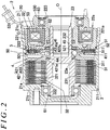
- FIG. 2 is a sectional view illustrating an example of the configuration of the drive force transfer device 2.
- the area above a rotational axis O indicates the drive force transfer device 2 in an operating state (torque transfer state), and the area below the rotational axis O indicates the drive force transfer device 2 in a non-operating state (non-torque transfer state).
- the direction parallel to the rotational axis O will be referred to as the "axial direction”.
- the drive force transfer device 2 has the housing 20, the tubular inner shaft 23, a main clutch 3, a cam mechanism 4, and an electromagnetic clutch mechanism 5.
- the housing 20 serves as an outer rotary member constituted from a front housing 21 and a rear housing 22.
- the inner shaft 23 serves as an inner rotary member supported coaxially with and so as to be rotatable relative to the housing 20.
- the main clutch 3 transfers a drive force between the housing 20 and the inner shaft 23.
- the cam mechanism 4 generates a pressing force for pressing the main clutch 3.
- the electromagnetic clutch mechanism 5 receives a rotational force of the front housing 21 to cause the cam mechanism 4 to operate. Lubricating oil (not illustrated) is sealed in an internal space of the housing 20.
- the cam mechanism 4 is an embodiment of a pressing mechanism that applies a pressing force to the main clutch 3.
- the front housing 21 has a bottomed cylindrical shape in which a cylindrical tubular portion 21a and a bottom portion 21b are integral with each other.
- a female thread portion 21c is formed in the inner surface of the opening end portion of the tubular portion 21a.
- the front housing 21 is made of a non-magnetic metal material such as aluminum.
- the propeller shaft 14 (see FIG. 1 ) is coupled to the bottom portion 21b via a cruciform joint, for example.
- the front housing 21 has a plurality of outer spline protrusions 211 provided on the inner peripheral surface of the tubular portion 21a such that the outer spline protrusions 211 extend in the axial direction.
- the outer spline protrusions 211 project radially inward toward the rotational axis O (illustrated in FIG. 1 ) of the housing 20 and the inner shaft 23.
- the rear housing 22 is composed of a first annular member 221, a second annular member 222, and a third annular member 223.
- the first annular member 221 is made of a magnetic material such as iron.
- the second annular member 222 is made of a non-magnetic material such as austenitic stainless steel, and integrally coupled to the inner peripheral side of the first annular member 221 by welding or the like.
- the third annular member 223 is made of a magnetic material such as iron, and integrally coupled to the inner peripheral side of the second annular member 222 by welding or the like.
- An annular housing space 22a that houses an electromagnetic coil 53 is formed between the first annular member 221 and the third annular member 223.
- a male thread portion 221a threadably engaged with the female thread portion 21c of the front housing 21 is formed on the outer peripheral surface of the first annular member 221.
- the inner shaft 23 is supported on the inner peripheral side of the housing 20 by a ball bearing 61 and a needle roller bearing 62.
- the inner shaft 23 has a plurality of inner spline protrusions 231 formed on the outer peripheral surface thereof such that the inner spline protrusions 231 extend in the axial direction.
- a spline fitting portion 232 is formed on the inner surface of one end portion of the inner shaft 23.
- One end portion of the pinion gear shaft 150 (see FIG. 1 ) is fitted with the spline fitting portion 232 so as not to be relatively rotatable.
- the main clutch 3 is a friction clutch that has a plurality of main outer clutch plates 31 and a plurality of main inner clutch plates 32 disposed alternately along the axial direction. Frictional sliding between the main outer clutch plates 31 and the main inner clutch plates 32 is lubricated by lubricating oil (not illustrated) sealed between the housing 20 and the inner shaft 23 to suppress wear and seizure.
- the main inner clutch plates 32 have a plurality of engagement protrusions 321 provided at the inner peripheral end portions thereof and engaged with the inner spline protrusions 231 of the inner shaft 23 with a backlash in the circumferential direction.
- a plurality of oil holes 322 that allow passage of lubricating oil are formed in the main inner clutch plates 32 on the inner side with respect to the main outer clutch plates 31. Rotation of the main inner clutch plates 32 relative to the inner shaft 23 is restricted with the engagement protrusions 321 engaged with the inner spline protrusions 231, and the main inner clutch plates 32 are movable with respect to the inner shaft 23 in the axial direction.
- the cam mechanism 4 has a pilot cam 41, a main cam 42, and a plurality of spherical cam balls 43.
- the pilot cam 41 receives a rotational force of the housing 20 via the electromagnetic clutch mechanism 5.
- the main cam 42 serves as a pressing member that presses the main clutch 3 in the axial direction.
- the cam balls 43 are disposed between the pilot cam 41 and the main cam 42.
- the pilot cam 41 has a spline engagement portion 411 at the outer peripheral end portion thereof.
- the spline engagement portion 411 receives a rotational force for rotation relative to the main cam 42 from the electromagnetic clutch mechanism 5.
- a needle roller thrust bearing 45 is disposed between the pilot cam 41 and the third annular member 223 of the rear housing 22.
- a plurality of cam grooves 41a and 422a are formed in opposing surfaces of the pilot cam 41 and the cam portion 422 of the main cam 42.
- the depths of the cam grooves 41a and 422a in the axial direction are varied along the circumferential direction.
- the cam balls 43 are each disposed between the cam groove 41a of the pilot cam 41 and the cam groove 422a of the main cam 42.
- the cam mechanism 4 generates a pressing force in the axial direction for pressing the main clutch 3 when the pilot cam 41 rotates relative to the main cam 42.
- the main clutch 3 transfers a drive force using a friction force when the main clutch 3 receives the pressing force from the cam mechanism 4 and the main outer clutch plates 31 and the main inner clutch plates 32 are brought into frictional contact with each other.
- the electromagnetic coil 53 is held by an annular yoke 530 made of a magnetic material, and housed in the housing space 22a of the rear housing 22.
- the yoke 530 is supported on the third annular member 223 of the rear housing 22 by a ball bearing 63, with the outer peripheral surface of the yoke 530 opposing the inner peripheral surface of the first annular member 221.
- the inner peripheral surface of the yoke 530 opposes the outer peripheral surface of the third annular member 223.
- An exciting current is supplied from the control device 10 to the electromagnetic coil 53 via a wire 531.
- the pilot outer clutch plates 51 and the pilot inner clutch plates 52 are disposed alternately along the axial direction between the armature 50 and the rear housing 22.
- a plurality of arcuate slits are formed in the center portions, in the radial direction, of the pilot outer clutch plates 51 and the pilot inner clutch plates 52. The slits prevent short-circuiting of magnetic flux generated by energization of the electromagnetic coil 53.
- the armature 50 is an annular member made of a magnetic material such as iron.
- a plurality of engagement protrusions 501 engaged with the outer spline protrusions 211 of the front housing 21 are formed on the outer peripheral portion of the armature 50. Consequently, the armature 50 is movable in the axial direction with respect to the front housing 21, and rotation of the armature 50 relative to the front housing 21 is restricted.
- FIG. 3 is a functional block diagram illustrating the functional configuration of the control device 10.
- the CPU 101 By executing the program stored in the storage unit 102, the CPU 101 functions as a vibrating state occurrence detector 111, a vibration occurrence preliminary state detector 112, a load computer 113, and a vibration suppression controller 114.
- the front-wheel slip can be detected when the rotational speed of the right front wheel 182 or the rotational speed of the left front wheel 181 is abruptly increased during 40 ms, for example.
- the rear-wheel slip can be detected when the rotational speed of the right rear wheel 192 or the rotational speed of the left rear wheel 191 is abruptly increased during 40 ms, for example.
- the rear-wheel drive shafts 171 and 172 are twisted.
- an elastic force is accumulated in the rear-wheel drive shafts 171 and 172.
- Rear-wheel slip occurs when the twisting force exceeds a friction force (static friction force) between the right and left rear wheels 192 and 191 and the road surface.
- the front-wheel slip is gradually reduced as the drive force which is transferred to the right and left front wheels 182 and 181 is decreased.
- the vibrating state occurrence detector 111 detects the occurrence of a vibrating state in which the right and left front wheels 182 and 181 and the right and left rear wheels 192 and 191 slip alternately in the four-wheel-drive state in which a drive force of the engine 11 is transferred to the right and left rear wheels 192 and 191 with the main clutch 3 of the drive force transfer device 2 engaged.
- the vibration occurrence preliminary state detector 112 detects the occurrence of a preliminary state in which a vibrating state, in which the right and left front wheels 182 and 181 and the right and left rear wheels 192 and 191 slip alternately, may occur.
- the vibrating state occurrence detector 111 detects the occurrence of a vibrating state in accordance with the occurrence of ⁇ N vibration in which a rotational speed difference (hereinafter referred to as " ⁇ N") obtained by subtracting the average rotational speed of the right and left rear wheels 192 and 191 from the average rotational speed of the right and left front wheels 182 and 181 becomes positive and negative cyclically.
- ⁇ N a rotational speed difference
- FIG. 4 is a graph that indicates an example of a state in which ⁇ N vibration occurs.
- the horizontal axis indicates the time, and the vertical axis indicates ⁇ N.
- the vibrating state occurrence detector 111 determines that ⁇ N vibration has occurred when ⁇ N becomes more than a positive predetermined value S1, ⁇ N becomes less than a negative predetermined value S2 within a predetermined period thereafter, ⁇ N becomes more than the positive predetermined value S1 within the predetermined period further thereafter, and such an event occurs repeatedly a plurality of (e.g. three) times. That is, the vibrating state occurrence detector 111 detects the occurrence of a vibrating state.
- the predetermined period is 50 to 150 ms, for example.
- the absolute values of the predetermined values S1 and S2 are 70 rpm, for example.
- ⁇ N becomes more than the positive predetermined value S1 at times t1 and t3, and ⁇ N becomes less than the negative predetermined value S2 at times t2 and t4. If a period from time t1 to time t2 and a period from time t2 to time t3 are within the predetermined period, the above event has occurred once during a period from time t1 to time t3.
- the vibration occurrence preliminary state detector 112 detects the occurrence of a preliminary state in the case where excessive slip has occurred at at least one of the right and left rear wheels 192 and 191 or in the case where slip has occurred at at least one of the right and left rear wheels 192 and 191 immediately after slip has occurred at at least one of the right and left front wheels 182 and 181.
- the vibration occurrence preliminary state detector 112 determines that excessive rear-wheel slip has occurred when the average rotational speed of the right and left rear wheels 192 and 191 is higher than the average rotational speed of the right and left front wheels 182 and 181 by 100 rpm or more, for example.
- the vibration occurrence preliminary state detector 112 detects that a preliminary state has occurred when rear-wheel slip has occurred within 0.2 seconds, for example, since the occurrence of front-wheel slip.
- FIG. 5 is a flowchart illustrating an example of the execution procedure of processing executed by the CPU 101 as the vibrating state occurrence detector 111, the vibration occurrence preliminary state detector 112, the load computer 113, and the vibration suppression controller 114.
- the CPU 101 repeatedly executes the processing illustrated in the flowchart in predetermined control cycles (e.g. in cycles of 5 ms).
- the electromagnetic coil 53 of the drive force transfer device 2 has been supplied in advance with an exciting current that generates a fastening force of the main clutch 3 that is not enough to cause relative rotation between the housing 20 and the inner shaft 23.
- a state in which the electromagnetic coil 53 is supplied with such an exciting current will be referred to as a "high torque state" of the drive force transfer device 2.
- a state in which the electromagnetic coil 53 is supplied with an exciting current that is enough to cause relative rotation between the housing 20 and the inner shaft 23 will be referred to as a "low torque state" of the drive force transfer device 2.
- the CPU 101 serves as the load computer 113, and computes a thermal load of the drive force transfer device 2 (step S1).
- the thermal load can be calculated by integrating, over a predetermined period, a value obtained by subtracting the amount of heat to be released, which is calculated in consideration of the outside temperature, from the amount of heat to be generated, which is calculated by multiplying transfer torque of the drive force transfer device 2 which matches the exciting current by the absolute value of ⁇ N, for example.
- the thermal load may be calculated on the basis of a value detected by the temperature sensor.
- the CPU 101 serves as the vibration occurrence preliminary state detector 112, and determines whether or not excessive rear-wheel slip has occurred (step S2).
- the CPU 101 serves as the vibration occurrence preliminary state detector 112, and determines whether or not rear-wheel slip has occurred immediately after front-wheel slip (step S3).
- the CPU 101 serves as the vibrating state occurrence detector 111, and determines whether or not cyclic ⁇ N vibration has occurred (step S4).
- the processing of the flowchart illustrated in FIG. 5 is ended.
- step S5 determines whether or not the vehicle speed is less than a predetermined threshold.
- the threshold used in step S5 is 30 km/h, for example.
- the vehicle speed can be calculated on the basis of the rotational speed of a wheel at the lowest rotational speed, among the right and left front wheels 182 and 181 and the right and left rear wheels 192 and 191, for example.
- the processing of the flowchart illustrated in FIG. 5 is ended.
- step S6 determines whether or not the thermal load of the drive force transfer device 2 computed in step S1 is less than a predetermined threshold (step S6).
- the threshold used in step S6 is set such that a portion of the drive force transfer device 2 that is the most sensitive to heat, e.g. the friction materials which are applied to the main outer clutch plates 31, is not damaged by overheating.
- step S6 determines that the thermal load of the drive force transfer device 2 is less than the predetermined threshold (S6: Yes).
- the CPU 101 controls the drive force transfer device 2 to the low torque state (step S7). Specifically, the CPU 101 reduces the exciting current to be supplied to the electromagnetic coil 53 to about half of that in the high torque state, for example.
- the fastening force of the main clutch 3 is weakened, which loosens coupling between the propeller shaft 14, which is a drive force transfer member closer to the front wheels than the drive force transfer device 2, and the pinion gear shaft 150, which is a drive force transfer member closer to the rear wheels than the drive force transfer device 2. Therefore, accumulation of twisting in the front-wheel drive shafts 161 and 162 and the rear-wheel drive shafts 171 and 172 is suppressed, so that ⁇ N vibration is suppressed.
- step S8 the CPU 101 controls the drive force transfer device 2 to the high torque state (step S8).
- the electromagnetic coil 53 is supplied with an exciting current that is not enough to cause the main outer clutch plates 31 and the main inner clutch plates 32 to frictionally slide on each other when the thermal load of the drive force transfer device 2 becomes high because of continuous occurrence of ⁇ N vibration, for example. Consequently, a further increase of the thermal load of the drive force transfer device 2 is suppressed, and damage due to heat is avoided.
- steps S5 to S8 is executed with the CPU 101 serving as the vibration suppression controller 114.
- the control device 10 reduces the drive force which is transferred to the right and left rear wheels 192 and 191 via the drive force transfer device 2 on condition that the thermal load of the drive force transfer device 2 is less than the predetermined threshold when a vibrating state or a preliminary state therefor is detected.
- This processing is performed in consideration of a fact that slipping tends to occur between the main outer clutch plates 31 and the main inner clutch plates 32, and damage due to overheating tends to occur with the thermal load of the drive force transfer device 2 further increased, if the fastening force of the main clutch 3 is weakened when the thermal load of the drive force transfer device 2 is high.
- the control device 10 reduces the drive force which is transferred to the right and left rear wheels 192 and 191 via the drive force transfer device 2 when a vibrating state or a preliminary state therefor is detected further on condition that the vehicle speed is less than the predetermined threshold.
- This processing is for the purpose of giving priority to the travel stability of the four-wheel-drive vehicle 1 in consideration of a fact that vibration that is enough to give a sense of discomfort or a sense of anxiety to a driver or a passenger occurs even if ⁇ N vibration occurs at the time other than starting.
Landscapes
- Engineering & Computer Science (AREA)
- Transportation (AREA)
- Mechanical Engineering (AREA)
- Chemical & Material Sciences (AREA)
- Combustion & Propulsion (AREA)
- Automation & Control Theory (AREA)
- Physics & Mathematics (AREA)
- Mathematical Physics (AREA)
- Arrangement And Driving Of Transmission Devices (AREA)
- Arrangement And Mounting Of Devices That Control Transmission Of Motive Force (AREA)
Abstract
Description
- The present invention relates to a four-wheel-drive vehicle control device, and in particular to a control device that controls a drive force transfer device that transfers a drive force to auxiliary drive wheels.
- There has hitherto been a four-wheel-drive vehicle control device mounted on a four-wheel-drive vehicle that has main drive wheels (e.g. front wheels) to which a drive force of a drive source such as an engine is always transferred and auxiliary drive wheels (e.g. rear wheels) to which a drive force of the drive source is transferred via a drive force transfer device that can adjust transfer torque. The four-wheel-drive vehicle control device controls the drive force transfer device in accordance with the vehicle travel state such as a wheel speed and a steering angle. In the four-wheel-drive vehicle control device, a four-wheel-drive state is established by enhancing transfer torque of the drive force transfer device when the vehicle starts on a road surface with a low friction coefficient such as an icy road and a compacted snow road. See Japanese Patent Application Publication No.
2008-184980 JP 2008-184980 A - When the vehicle starts in the four-wheel-drive state, the drive force is distributed to the front and rear wheels to suppress the occurrence of slip. When slip occurs at the front wheels or the rear wheels when the vehicle starts in the four-wheel-drive state, however, a vibrating state in which the wheel speed of the front wheels and the wheel speed of the rear wheels are alternately increased may be caused.
JP 2008-184980 A - As described above, it is possible to gradually reduce self-excited vibration by controlling engine torque or a braking force or transfer torque of the drive force transfer device when self-excited vibration occurs. When the vehicle starts after self-excited vibration is gradually reduced, however, self-excited vibration may occur again. If self-excited vibration repeatedly occurs in this way, a clutch or the like that transfers torque in the drive force transfer device may be heated.
- It is an object of the present invention to provide a four-wheel-drive vehicle control device that can prevent damage, due to a thermal load, to a drive force transfer device that transfers a drive force to auxiliary drive wheels even if a vibrating state in which main drive wheels and the auxiliary drive wheels slip alternately occurs when the vehicle starts on a road surface with a low friction coefficient.
- An aspect of the present invention provides a four-wheel-drive vehicle control device mounted on a four-wheel-drive vehicle that has main drive wheels, to which a drive force of a drive source of the vehicle is always transferred, and auxiliary drive wheels, to which a drive force of the drive source is transferred via a drive force transfer device so as to be adjustable in accordance with a travel state of the vehicle, and the four-wheel-drive vehicle control device controls the drive force transfer device.
The four-wheel-drive vehicle control device includes: - a detector that detects occurrence of a vibrating state, in which the main drive wheels and the auxiliary drive wheels slip alternately in a four-wheel-drive state in which a drive force is transferred to the auxiliary drive wheels, or occurrence of a preliminary state, in which the vibrating state may occur; and
- a vibration suppression controller that reduces the drive force which is transferred to the auxiliary drive wheels via the drive force transfer device when the vibrating state or the preliminary state is detected by the detector.
- With the four-wheel-drive vehicle control device according to the above aspect, it is possible to prevent damage, due to a thermal load, to a drive force transfer device that transfers a drive force to auxiliary drive wheels even if a vibrating state in which main drive wheels and the auxiliary drive wheels slip alternately occurs when the vehicle starts on a road surface with a low friction coefficient.
- The foregoing and further features and advantages of the invention will become apparent from the following description of example embodiments with reference to the accompanying drawings, wherein like numerals are used to represent like elements and wherein:
-
FIG. 1 is a schematic diagram schematically illustrating an example of the configuration of a four-wheel-drive vehicle on which a drive force transfer device according to an embodiment of the present invention is mounted; -
FIG. 2 is a sectional view illustrating an example of the configuration of the drive force transfer device; -
FIG. 3 is a functional block diagram illustrating the functional configuration of a control device; -
FIG. 4 is a graph that indicates an example of a state in which ΔN vibration occurs; and -
FIG. 5 is a flowchart illustrating an example of the procedure of processing executed by the control device. - An embodiment of the present invention will be described with reference to
FIGS. 1 to 5 . -
FIG. 1 is a schematic diagram schematically illustrating an example of the configuration of a four-wheel-drive vehicle on which a drive force transfer device according to an embodiment of the present invention is mounted. - As illustrated in
FIG. 1 , a four-wheel-drive vehicle 1 includes anengine 11, atransmission 12, right and leftfront wheels rear wheels engine 11 serves as a drive source that generates torque for travel. Thetransmission 12 varies the speed of an output from theengine 11. The right and leftfront wheels engine 11 is always transferred after the speed of the drive force has been varied by thetransmission 12. The right and leftrear wheels engine 11 is transferred in accordance with the travel state of the four-wheel-drive vehicle 1. The four-wheel-drive vehicle 1 is switchable between a four-wheel-drive state, in which a drive force of theengine 11 is transferred to the right and leftfront wheels rear wheels front wheels - The four-wheel-
drive vehicle 1 also includes, mounted thereon, afront differential 13, apropeller shaft 14, arear differential 15, right and left front-wheel drive shafts wheel drive shafts force transfer device 2 disposed between thepropeller shaft 14 and therear differential 15, and acontrol device 10 that controls the driveforce transfer device 2. - The
control device 10 can acquire the results of detection byrotational speed sensors front wheels rear wheels accelerator pedal sensor 75 that detects the amount by which anaccelerator pedal 100 is depressed, and controls the driveforce transfer device 2 on the basis of such detection results. More specifically, thecontrol device 10 controls the driveforce transfer device 2 such that a larger drive force is transferred to the right and leftrear wheels front wheels rear wheels accelerator pedal 100 is depressed is larger. - The
control device 10 computes instruction torque to be transferred by the driveforce transfer device 2 on the basis of the results of detection by therotational speed sensors 71 to 74 and theaccelerator pedal sensor 75, and supplies the driveforce transfer device 2 with an exciting current that matches the instruction torque. The driveforce transfer device 2 transfers a drive force that matches the exciting current from thepropeller shaft 14 toward therear differential 15. Thecontrol device 10 can adjust a drive force transferred to the right and leftrear wheels force transfer device 2 by increasing and decreasing the exciting current through PWM control, for example. - A drive force of the
engine 11 is transferred to the right and leftfront wheels transmission 12, thefront differential 13, and the right and left front-wheel drive shafts front differential 13 has a pair ofside gears 131, a pair ofpinion gears 132, a pinion gear shaft 133, and a frontdifferential case 134. Theside gears 131 are coupled to the right and left front-wheel drive shafts pinion gears 132 are meshed with theside gears 131 with their gear shafts orthogonal to each other. The pinion gear shaft 133 supports thepinion gears 132. The frontdifferential case 134 houses theside gears 131, thepinion gears 132, and the pinion gear shaft 133. - A
ring gear 135 is fixed to the frontdifferential case 134. Thering gear 135 is meshed with apinion gear 141 provided at an end portion of thepropeller shaft 14 on the front side of the vehicle. An end portion of thepropeller shaft 14 on the rear side of the vehicle is coupled to ahousing 20 of the driveforce transfer device 2. The driveforce transfer device 2 has aninner shaft 23 disposed so as to be rotatable relative to thehousing 20, and transfers a drive force that matches the exciting current which is supplied from thecontrol device 10 to therear differential 15 via apinion gear shaft 150 coupled to theinner shaft 23 so as not to be relatively rotatable. The driveforce transfer device 2 will be discussed in detail later. - The
rear differential 15 has a pair ofside gears 151, a pair ofpinion gears 152, apinion gear shaft 153, a reardifferential case 154, and aring gear 155. Theside gears 151 are coupled to the right and left rear-wheel drive shafts pinion gears 152 are meshed with theside gears 151 with their gear shafts orthogonal to each other. Thepinion gear shaft 153 supports thepinion gears 152. The reardifferential case 154 houses theside gears 151, thepinion gears 152, and thepinion gear shaft 153. Thering gear 155 is fixed to the reardifferential case 154, and meshed with thepinion gear shaft 150. -
FIG. 2 is a sectional view illustrating an example of the configuration of the driveforce transfer device 2. InFIG. 2 , the area above a rotational axis O indicates the driveforce transfer device 2 in an operating state (torque transfer state), and the area below the rotational axis O indicates the driveforce transfer device 2 in a non-operating state (non-torque transfer state). Hereinafter, the direction parallel to the rotational axis O will be referred to as the "axial direction". - The drive
force transfer device 2 has thehousing 20, the tubularinner shaft 23, amain clutch 3, a cam mechanism 4, and an electromagneticclutch mechanism 5. Thehousing 20 serves as an outer rotary member constituted from afront housing 21 and arear housing 22. Theinner shaft 23 serves as an inner rotary member supported coaxially with and so as to be rotatable relative to thehousing 20. Themain clutch 3 transfers a drive force between thehousing 20 and theinner shaft 23. The cam mechanism 4 generates a pressing force for pressing themain clutch 3. The electromagneticclutch mechanism 5 receives a rotational force of thefront housing 21 to cause the cam mechanism 4 to operate. Lubricating oil (not illustrated) is sealed in an internal space of thehousing 20. The cam mechanism 4 is an embodiment of a pressing mechanism that applies a pressing force to themain clutch 3. - The
front housing 21 has a bottomed cylindrical shape in which a cylindricaltubular portion 21a and abottom portion 21b are integral with each other. Afemale thread portion 21c is formed in the inner surface of the opening end portion of thetubular portion 21a. Thefront housing 21 is made of a non-magnetic metal material such as aluminum. The propeller shaft 14 (seeFIG. 1 ) is coupled to thebottom portion 21b via a cruciform joint, for example. - The
front housing 21 has a plurality ofouter spline protrusions 211 provided on the inner peripheral surface of thetubular portion 21a such that theouter spline protrusions 211 extend in the axial direction. Theouter spline protrusions 211 project radially inward toward the rotational axis O (illustrated inFIG. 1 ) of thehousing 20 and theinner shaft 23. - The
rear housing 22 is composed of a first annular member 221, a secondannular member 222, and a thirdannular member 223. The first annular member 221 is made of a magnetic material such as iron. The secondannular member 222 is made of a non-magnetic material such as austenitic stainless steel, and integrally coupled to the inner peripheral side of the first annular member 221 by welding or the like. The thirdannular member 223 is made of a magnetic material such as iron, and integrally coupled to the inner peripheral side of the secondannular member 222 by welding or the like. Anannular housing space 22a that houses anelectromagnetic coil 53 is formed between the first annular member 221 and the thirdannular member 223. Amale thread portion 221a threadably engaged with thefemale thread portion 21c of thefront housing 21 is formed on the outer peripheral surface of the first annular member 221. - The
inner shaft 23 is supported on the inner peripheral side of thehousing 20 by aball bearing 61 and aneedle roller bearing 62. Theinner shaft 23 has a plurality ofinner spline protrusions 231 formed on the outer peripheral surface thereof such that theinner spline protrusions 231 extend in the axial direction. A splinefitting portion 232 is formed on the inner surface of one end portion of theinner shaft 23. One end portion of the pinion gear shaft 150 (seeFIG. 1 ) is fitted with the splinefitting portion 232 so as not to be relatively rotatable. - The
main clutch 3 is a friction clutch that has a plurality of main outerclutch plates 31 and a plurality of main innerclutch plates 32 disposed alternately along the axial direction. Frictional sliding between the main outerclutch plates 31 and the main innerclutch plates 32 is lubricated by lubricating oil (not illustrated) sealed between thehousing 20 and theinner shaft 23 to suppress wear and seizure. - The main outer
clutch plates 31 have a plurality ofengagement protrusions 311 provided at the outer peripheral end portions thereof and engaged with theouter spline protrusions 211 of thefront housing 21. Rotation of the main outerclutch plates 31 relative to thefront housing 21 is restricted with theengagement protrusions 311 engaged with theouter spline protrusions 211, and the main outerclutch plates 31 are movable in the axial direction with respect to thefront housing 21. - The main inner
clutch plates 32 have a plurality ofengagement protrusions 321 provided at the inner peripheral end portions thereof and engaged with theinner spline protrusions 231 of theinner shaft 23 with a backlash in the circumferential direction. A plurality ofoil holes 322 that allow passage of lubricating oil are formed in the main innerclutch plates 32 on the inner side with respect to the main outerclutch plates 31. Rotation of the main innerclutch plates 32 relative to theinner shaft 23 is restricted with theengagement protrusions 321 engaged with theinner spline protrusions 231, and the main innerclutch plates 32 are movable with respect to theinner shaft 23 in the axial direction. - The cam mechanism 4 has a pilot cam 41, a
main cam 42, and a plurality ofspherical cam balls 43. The pilot cam 41 receives a rotational force of thehousing 20 via the electromagneticclutch mechanism 5. Themain cam 42 serves as a pressing member that presses themain clutch 3 in the axial direction. Thecam balls 43 are disposed between the pilot cam 41 and themain cam 42. - The
main cam 42 integrally has apressing portion 421 in an annular plate shape and acam portion 422. Thepressing portion 421 contacts the main innerclutch plate 32 at one end of themain clutch 3 to press themain clutch 3. Thecam portion 422 is provided on the inner peripheral side of themain cam 42 with respect to thepressing portion 421. Rotation of themain cam 42 relative to theinner shaft 23 is restricted with aspline engagement portion 421a formed at the inner peripheral end portion of thepressing portion 421 engaged with theinner spline protrusions 231 of theinner shaft 23. Themain cam 42 is urged away from themain clutch 3 in the axial direction by adisc spring 44 disposed between a steppedsurface 23a formed on theinner shaft 23 and themain cam 42. - The pilot cam 41 has a
spline engagement portion 411 at the outer peripheral end portion thereof. Thespline engagement portion 411 receives a rotational force for rotation relative to themain cam 42 from the electromagneticclutch mechanism 5. A needle roller thrust bearing 45 is disposed between the pilot cam 41 and the thirdannular member 223 of therear housing 22. - A plurality of
cam grooves 41a and 422a are formed in opposing surfaces of the pilot cam 41 and thecam portion 422 of themain cam 42. The depths of thecam grooves 41a and 422a in the axial direction are varied along the circumferential direction. Thecam balls 43 are each disposed between the cam groove 41a of the pilot cam 41 and thecam groove 422a of themain cam 42. The cam mechanism 4 generates a pressing force in the axial direction for pressing themain clutch 3 when the pilot cam 41 rotates relative to themain cam 42. Themain clutch 3 transfers a drive force using a friction force when themain clutch 3 receives the pressing force from the cam mechanism 4 and the main outerclutch plates 31 and the main innerclutch plates 32 are brought into frictional contact with each other. - The electromagnetic
clutch mechanism 5 has anarmature 50, a plurality of pilot outerclutch plates 51, a plurality of pilot innerclutch plates 52, and theelectromagnetic coil 53. - The
electromagnetic coil 53 is held by anannular yoke 530 made of a magnetic material, and housed in thehousing space 22a of therear housing 22. Theyoke 530 is supported on the thirdannular member 223 of therear housing 22 by aball bearing 63, with the outer peripheral surface of theyoke 530 opposing the inner peripheral surface of the first annular member 221. The inner peripheral surface of theyoke 530 opposes the outer peripheral surface of the thirdannular member 223. An exciting current is supplied from thecontrol device 10 to theelectromagnetic coil 53 via awire 531. - The pilot outer
clutch plates 51 and the pilot innerclutch plates 52 are disposed alternately along the axial direction between thearmature 50 and therear housing 22. A plurality of arcuate slits are formed in the center portions, in the radial direction, of the pilot outerclutch plates 51 and the pilot innerclutch plates 52. The slits prevent short-circuiting of magnetic flux generated by energization of theelectromagnetic coil 53. - The pilot outer
clutch plates 51 have a plurality ofengagement protrusions 511 provided at the outer peripheral end portions thereof and engaged with theouter spline protrusions 211 of thefront housing 21. The pilot innerclutch plates 52 have a plurality ofengagement protrusions 521 provided at the inner peripheral end portions thereof and engaged with thespline engagement portion 411 of the pilot cam 41. - The
armature 50 is an annular member made of a magnetic material such as iron. A plurality ofengagement protrusions 501 engaged with theouter spline protrusions 211 of thefront housing 21 are formed on the outer peripheral portion of thearmature 50. Consequently, thearmature 50 is movable in the axial direction with respect to thefront housing 21, and rotation of thearmature 50 relative to thefront housing 21 is restricted. - In the drive
force transfer device 2 configured as described above, thearmature 50 is attracted toward therear housing 22 by a magnetic force generated when an exciting current is supplied to theelectromagnetic coil 53, and the pilot outerclutch plates 51 and the pilot innerclutch plates 52 are brought into frictional contact with each other. Consequently, a rotational force of thehousing 20 is transferred to the pilot cam 41, the pilot cam 41 is rotated relative to themain cam 42, and thecam balls 43 are rolled in thecam grooves 41a and 422a. With thecam balls 43 rolling, cam thrust that presses themain clutch 3 is generated in themain cam 42, and a friction force is generated between the main outerclutch plates 31 and the main innerclutch plates 32. Torque is transferred between thehousing 20 and theinner shaft 23 using the friction force. Torque transferred by themain clutch 3 is increased and decreased in accordance with the exciting current which is supplied to theelectromagnetic coil 53. - The
control device 10 has aCPU 101 and astorage unit 102. TheCPU 101 serves as a computation processing device. Thestorage unit 102 is composed of a semiconductor storage element such as a ROM and a RAM. TheCPU 101 executes a program stored in thestorage unit 102. -
FIG. 3 is a functional block diagram illustrating the functional configuration of thecontrol device 10. By executing the program stored in thestorage unit 102, theCPU 101 functions as a vibratingstate occurrence detector 111, a vibration occurrencepreliminary state detector 112, a load computer 113, and avibration suppression controller 114. - The
control device 10 has many functions other than the functions implemented by such components. However, the following description will focus on two types of processing: processing for suppressing a vibrating state in which a state (hereinafter referred to as "front-wheel slip") in which slip occurs at at least one of the right and leftfront wheels 182 and 181 (at least one of the rightfront wheel 182 and the left front wheel 181) and a state (hereinafter referred to as "rear-wheel slip") in which slip occurs at at least one of the right and leftrear wheels 192 and 191 (at least one of the rightrear wheel 192 and the left rear wheel 191) occur alternately when the four-wheel-drive vehicle 1 starts; and processing for preventing the driveforce transfer device 2 from being overloaded during the processing for suppressing the vibrating state.. - The front-wheel slip can be detected when the rotational speed of the right
front wheel 182 or the rotational speed of the leftfront wheel 181 is abruptly increased during 40 ms, for example. Similarly, the rear-wheel slip can be detected when the rotational speed of the rightrear wheel 192 or the rotational speed of the leftrear wheel 191 is abruptly increased during 40 ms, for example. - Such a vibrating state may be caused in the case where the vehicle starts in a four-wheel-drive state on a road surface with a low friction coefficient such as an icy road, a compacted snow road, or the like, for example. More specifically, when rotation of the
engine 11 is output as a drive force with the speed of the rotation varied by thetransmission 12 in the four-wheel-drive state, the drive force is distributed generally equally to the right and leftfront wheels rear wheels front wheels rear wheels wheel drive shafts wheel drive shafts rear wheels front wheels - When rear-wheel slip occurs, conversely to the time when front-wheel slip occurs, substantially no drive force is transferred to the right and left
rear wheels front wheels wheel drive shafts front wheels drive vehicle 1 remaining unable to start. - In order to prevent continuation of the vibrating state, it is desirable to reduce the fastening force of the
main clutch 3 of the driveforce transfer device 2, and to suppress the occurrence of twisting that is large enough to cause slip of the front-wheel drive shafts wheel drive shafts main clutch 3, however, the main outerclutch plates 31 and the main innerclutch plates 32 frictionally slide on each other while being pressed against each other, and thus themain clutch 3 is heated, which may damage frictional materials applied to the main outerclutch plates 31, for example. In the embodiment, such damage to the driveforce transfer device 2 is prevented by control processing discussed below. - The vibrating
state occurrence detector 111 detects the occurrence of a vibrating state in which the right and leftfront wheels rear wheels engine 11 is transferred to the right and leftrear wheels main clutch 3 of the driveforce transfer device 2 engaged. The vibration occurrencepreliminary state detector 112 detects the occurrence of a preliminary state in which a vibrating state, in which the right and leftfront wheels rear wheels - The vibrating
state occurrence detector 111 detects the occurrence of a vibrating state in accordance with the occurrence of ΔN vibration in which a rotational speed difference (hereinafter referred to as "ΔN") obtained by subtracting the average rotational speed of the right and leftrear wheels front wheels -
FIG. 4 is a graph that indicates an example of a state in which ΔN vibration occurs. The horizontal axis indicates the time, and the vertical axis indicates ΔN. The vibratingstate occurrence detector 111 determines that ΔN vibration has occurred when ΔN becomes more than a positive predetermined value S1, ΔN becomes less than a negative predetermined value S2 within a predetermined period thereafter, ΔN becomes more than the positive predetermined value S1 within the predetermined period further thereafter, and such an event occurs repeatedly a plurality of (e.g. three) times. That is, the vibratingstate occurrence detector 111 detects the occurrence of a vibrating state. The predetermined period is 50 to 150 ms, for example. The absolute values of the predetermined values S1 and S2 are 70 rpm, for example. - In the example illustrated in
FIG. 4 , ΔN becomes more than the positive predetermined value S1 at times t1 and t3, and ΔN becomes less than the negative predetermined value S2 at times t2 and t4. If a period from time t1 to time t2 and a period from time t2 to time t3 are within the predetermined period, the above event has occurred once during a period from time t1 to time t3. - The vibration occurrence
preliminary state detector 112 detects the occurrence of a preliminary state in the case where excessive slip has occurred at at least one of the right and leftrear wheels rear wheels front wheels preliminary state detector 112 determines that excessive rear-wheel slip has occurred when the average rotational speed of the right and leftrear wheels front wheels preliminary state detector 112 detects that a preliminary state has occurred when rear-wheel slip has occurred within 0.2 seconds, for example, since the occurrence of front-wheel slip. -
FIG. 5 is a flowchart illustrating an example of the execution procedure of processing executed by theCPU 101 as the vibratingstate occurrence detector 111, the vibration occurrencepreliminary state detector 112, the load computer 113, and thevibration suppression controller 114. TheCPU 101 repeatedly executes the processing illustrated in the flowchart in predetermined control cycles (e.g. in cycles of 5 ms). - In the case where the four-wheel-
drive vehicle 1 has not started (the vehicle speed is zero), theelectromagnetic coil 53 of the driveforce transfer device 2 has been supplied in advance with an exciting current that generates a fastening force of themain clutch 3 that is not enough to cause relative rotation between thehousing 20 and theinner shaft 23. Hereinafter, a state in which theelectromagnetic coil 53 is supplied with such an exciting current will be referred to as a "high torque state" of the driveforce transfer device 2. Meanwhile, a state in which theelectromagnetic coil 53 is supplied with an exciting current that is enough to cause relative rotation between thehousing 20 and theinner shaft 23 will be referred to as a "low torque state" of the driveforce transfer device 2. - In one control cycle, first, the
CPU 101 serves as the load computer 113, and computes a thermal load of the drive force transfer device 2 (step S1). The thermal load can be calculated by integrating, over a predetermined period, a value obtained by subtracting the amount of heat to be released, which is calculated in consideration of the outside temperature, from the amount of heat to be generated, which is calculated by multiplying transfer torque of the driveforce transfer device 2 which matches the exciting current by the absolute value of ΔN, for example. Alternatively, in the case where a temperature sensor is attached to the driveforce transfer device 2, the thermal load may be calculated on the basis of a value detected by the temperature sensor. - Next, the
CPU 101 serves as the vibration occurrencepreliminary state detector 112, and determines whether or not excessive rear-wheel slip has occurred (step S2). In the case where it is determined that excessive rear-wheel slip has not occurred (S2: No), theCPU 101 serves as the vibration occurrencepreliminary state detector 112, and determines whether or not rear-wheel slip has occurred immediately after front-wheel slip (step S3). In the case where it is determined that rear-wheel slip has not occurred immediately after front-wheel slip (S3: No), theCPU 101 serves as the vibratingstate occurrence detector 111, and determines whether or not cyclic ΔN vibration has occurred (step S4). As a result of the determination (S4: No), in the case where cyclic ΔN vibration has not occurred, the processing of the flowchart illustrated inFIG. 5 is ended. - On the other hand, in the case where it is determined that excessive rear-wheel slip has occurred (S2: Yes), in the case where it is determined that rear-wheel slip has occurred immediately after front-wheel slip (S3: Yes), or in the case where it is determined that cyclic ΔN vibration has occurred (S4: Yes), the
CPU 101 determines whether or not the vehicle speed is less than a predetermined threshold (step S5). The threshold used in step S5 is 30 km/h, for example. The vehicle speed can be calculated on the basis of the rotational speed of a wheel at the lowest rotational speed, among the right and leftfront wheels rear wheels FIG. 5 is ended. - In the case where it is determined in the processing in step S5 that the vehicle speed is less than the predetermined threshold (S5: Yes), the
CPU 101 determines whether or not the thermal load of the driveforce transfer device 2 computed in step S1 is less than a predetermined threshold (step S6). The threshold used in step S6 is set such that a portion of the driveforce transfer device 2 that is the most sensitive to heat, e.g. the friction materials which are applied to the main outerclutch plates 31, is not damaged by overheating. - In the case where it is determined in the processing of step S6 that the thermal load of the drive
force transfer device 2 is less than the predetermined threshold (S6: Yes), theCPU 101 controls the driveforce transfer device 2 to the low torque state (step S7). Specifically, theCPU 101 reduces the exciting current to be supplied to theelectromagnetic coil 53 to about half of that in the high torque state, for example. Through this processing, the fastening force of themain clutch 3 is weakened, which loosens coupling between thepropeller shaft 14, which is a drive force transfer member closer to the front wheels than the driveforce transfer device 2, and thepinion gear shaft 150, which is a drive force transfer member closer to the rear wheels than the driveforce transfer device 2. Therefore, accumulation of twisting in the front-wheel drive shafts wheel drive shafts - In the case where the thermal load of the drive
force transfer device 2 is not less than the predetermined threshold in the processing of step S6 (S6: No), on the other hand, theCPU 101 controls the driveforce transfer device 2 to the high torque state (step S8). Through this processing, theelectromagnetic coil 53 is supplied with an exciting current that is not enough to cause the main outerclutch plates 31 and the main innerclutch plates 32 to frictionally slide on each other when the thermal load of the driveforce transfer device 2 becomes high because of continuous occurrence of ΔN vibration, for example. Consequently, a further increase of the thermal load of the driveforce transfer device 2 is suppressed, and damage due to heat is avoided. - The processing in steps S5 to S8 is executed with the
CPU 101 serving as thevibration suppression controller 114. - As described above, the
control device 10 reduces the drive force which is transferred to the right and leftrear wheels force transfer device 2 on condition that the thermal load of the driveforce transfer device 2 is less than the predetermined threshold when a vibrating state or a preliminary state therefor is detected. This processing is performed in consideration of a fact that slipping tends to occur between the main outerclutch plates 31 and the main innerclutch plates 32, and damage due to overheating tends to occur with the thermal load of the driveforce transfer device 2 further increased, if the fastening force of themain clutch 3 is weakened when the thermal load of the driveforce transfer device 2 is high. - The
control device 10 reduces the drive force which is transferred to the right and leftrear wheels force transfer device 2 when a vibrating state or a preliminary state therefor is detected further on condition that the vehicle speed is less than the predetermined threshold. This processing is for the purpose of giving priority to the travel stability of the four-wheel-drive vehicle 1 in consideration of a fact that vibration that is enough to give a sense of discomfort or a sense of anxiety to a driver or a passenger occurs even if ΔN vibration occurs at the time other than starting. - According to the embodiment described above, it is possible to prevent damage, due to the thermal load, to the drive
force transfer device 2 while suppressing a vibrating state, in which the right and leftfront wheels rear wheels force transfer device 2 even if the vibrating state occurs when the vehicle starts on a road surface with a low friction coefficient. - A
control device 10 is mounted on a four-wheel-drive vehicle 1, and includes a detector and a vibration suppression controller. The detector detects the occurrence of a vibrating state, in which drive wheels and auxiliary drive wheels slip alternately in a four-wheel-drive state in which a drive force is transferred to the auxiliary drive wheels, or the occurrence of a preliminary state for the vibrating state. The vibration suppression controller reduces the drive force which is transferred to the auxiliary drive wheels via a driveforce transfer device 2 when the vibrating state or the preliminary state is detected by the detector. The vibration suppression controller reduces the drive force which is transferred to the auxiliary drive wheels on condition that a thermal load of the driveforce transfer device 2 is less than a predetermined threshold.
Claims (2)
- A four-wheel-drive vehicle control device mounted on a four-wheel-drive vehicle that has main drive wheels, to which a drive force of a drive source of the vehicle is always transferred, and auxiliary drive wheels, to which a drive force of the drive source is transferred via a drive force transfer device so as to be adjustable in accordance with a travel state of the vehicle, the four-wheel-drive vehicle control device controlling the drive force transfer device and comprising:a detector that detects occurrence of a vibrating state, in which the main drive wheels and the auxiliary drive wheels slip alternately in a four-wheel-drive state in which a drive force is transferred to the auxiliary drive wheels, or occurrence of a preliminary state, in which the vibrating state may occur; anda vibration suppression controller that reduces the drive force which is transferred to the auxiliary drive wheels via the drive force transfer device when the vibrating state or the preliminary state is detected by the detector, whereinthe vibration suppression controller is configured to reduce the drive force which is transferred to the auxiliary drive wheels on condition that a thermal load of the drive force transfer device is less than a predetermined threshold.
- The four-wheel-drive vehicle control device according to claim 1, wherein
the vibration suppression controller is configured to reduce the drive force which is transferred to the auxiliary drive wheels further on condition that a vehicle speed is less than a predetermined threshold when the vibrating state or the preliminary state is detected by the detector.
Applications Claiming Priority (1)
| Application Number | Priority Date | Filing Date | Title |
|---|---|---|---|
| JP2016181514A JP6786986B2 (en) | 2016-09-16 | 2016-09-16 | Control device for four-wheel drive vehicles |
Publications (2)
| Publication Number | Publication Date |
|---|---|
| EP3296137A1 true EP3296137A1 (en) | 2018-03-21 |
| EP3296137B1 EP3296137B1 (en) | 2019-12-18 |
Family
ID=59858957
Family Applications (1)
| Application Number | Title | Priority Date | Filing Date |
|---|---|---|---|
| EP17191008.6A Active EP3296137B1 (en) | 2016-09-16 | 2017-09-14 | Four-wheel-drive vehicle control device |
Country Status (4)
| Country | Link |
|---|---|
| US (1) | US10639989B2 (en) |
| EP (1) | EP3296137B1 (en) |
| JP (1) | JP6786986B2 (en) |
| CN (1) | CN107826111B (en) |
Families Citing this family (5)
| Publication number | Priority date | Publication date | Assignee | Title |
|---|---|---|---|---|
| JP7331467B2 (en) * | 2019-05-30 | 2023-08-23 | 株式会社ジェイテクト | four wheel drive |
| JP6933688B2 (en) * | 2019-07-09 | 2021-09-08 | 本田技研工業株式会社 | Vehicle control device, vehicle and vehicle control method |
| DE102020118923B4 (en) * | 2020-07-17 | 2025-01-30 | Audi Aktiengesellschaft | Motor vehicle with a four-wheel drive, comprising a drivable front and rear axle, an internal combustion engine and an electric motor |
| KR102907201B1 (en) * | 2020-08-25 | 2025-12-31 | 현대모비스 주식회사 | Method And Apparatus for Controlling Driving Force for Dual-Motor-Equipped Vehicle |
| CN112092612B (en) * | 2020-09-18 | 2021-12-07 | 中国第一汽车股份有限公司 | Four-wheel drive pure electric vehicle power system |
Citations (5)
| Publication number | Priority date | Publication date | Assignee | Title |
|---|---|---|---|---|
| DE102006022858A1 (en) * | 2006-05-16 | 2007-11-22 | Magna Powertrain Ag & Co Kg | Pressure reduction unit for a hydromechanical, responsive to a speed difference clutch |
| JP2008184980A (en) | 2007-01-30 | 2008-08-14 | Mazda Motor Corp | Four-wheel drive vehicle control system |
| JP2010188774A (en) * | 2009-02-16 | 2010-09-02 | Jtekt Corp | Clutch device for four-wheel drive vehicle, and drive force distribution method for four-wheel drive vehicle |
| DE102009032265A1 (en) * | 2009-07-08 | 2011-01-13 | Magna Powertrain Ag & Co Kg | Method for protecting wheel coupling, involves arranging wheel coupling in drive train of motor vehicle, where failure of sensors, is determined, and substitute value is determined for rotation speed value of utilization factor |
| US20160039403A1 (en) * | 2014-08-07 | 2016-02-11 | Jtekt Corporation | Device and method for controlling limited slip differential |
Family Cites Families (9)
| Publication number | Priority date | Publication date | Assignee | Title |
|---|---|---|---|---|
| KR100466380B1 (en) * | 2000-09-19 | 2005-01-13 | 닛산 지도우샤 가부시키가이샤 | Apparatus for estimating clutch temperature |
| JP3807232B2 (en) * | 2001-02-02 | 2006-08-09 | 日産自動車株式会社 | Hybrid vehicle control system |
| US7630812B2 (en) * | 2004-02-09 | 2009-12-08 | Ford Global Technologies, Llc | Method and system for controlling a transfer case clutch to protect against excessive heat |
| US8197386B2 (en) * | 2005-08-11 | 2012-06-12 | American Axle & Manufacturing, Inc. | Electrohydraulic torque transfer device and temperature control system |
| JP4973222B2 (en) * | 2007-02-14 | 2012-07-11 | トヨタ自動車株式会社 | Driving force control device for four-wheel drive vehicle |
| US8095288B2 (en) * | 2009-04-17 | 2012-01-10 | Ford Global Technologies, Llc | Reducing oscillations in a motor vehicle driveline |
| BR112013018720A2 (en) * | 2011-01-27 | 2017-02-07 | Honda Motor Co Ltd | propulsive force control device for four-wheel drive vehicle |
| WO2012132996A1 (en) * | 2011-03-31 | 2012-10-04 | 株式会社ジェイテクト | Driving force distribution controller and four-wheel drive vehicle |
| JP5808601B2 (en) * | 2011-08-01 | 2015-11-10 | 株式会社ジェイテクト | Driving force distribution control device and four-wheel drive vehicle |
-
2016
- 2016-09-16 JP JP2016181514A patent/JP6786986B2/en not_active Expired - Fee Related
-
2017
- 2017-09-14 US US15/704,091 patent/US10639989B2/en not_active Expired - Fee Related
- 2017-09-14 EP EP17191008.6A patent/EP3296137B1/en active Active
- 2017-09-15 CN CN201710832271.7A patent/CN107826111B/en not_active Expired - Fee Related
Patent Citations (5)
| Publication number | Priority date | Publication date | Assignee | Title |
|---|---|---|---|---|
| DE102006022858A1 (en) * | 2006-05-16 | 2007-11-22 | Magna Powertrain Ag & Co Kg | Pressure reduction unit for a hydromechanical, responsive to a speed difference clutch |
| JP2008184980A (en) | 2007-01-30 | 2008-08-14 | Mazda Motor Corp | Four-wheel drive vehicle control system |
| JP2010188774A (en) * | 2009-02-16 | 2010-09-02 | Jtekt Corp | Clutch device for four-wheel drive vehicle, and drive force distribution method for four-wheel drive vehicle |
| DE102009032265A1 (en) * | 2009-07-08 | 2011-01-13 | Magna Powertrain Ag & Co Kg | Method for protecting wheel coupling, involves arranging wheel coupling in drive train of motor vehicle, where failure of sensors, is determined, and substitute value is determined for rotation speed value of utilization factor |
| US20160039403A1 (en) * | 2014-08-07 | 2016-02-11 | Jtekt Corporation | Device and method for controlling limited slip differential |
Also Published As
| Publication number | Publication date |
|---|---|
| JP2018043703A (en) | 2018-03-22 |
| CN107826111A (en) | 2018-03-23 |
| US10639989B2 (en) | 2020-05-05 |
| US20180079301A1 (en) | 2018-03-22 |
| JP6786986B2 (en) | 2020-11-18 |
| EP3296137B1 (en) | 2019-12-18 |
| CN107826111B (en) | 2022-06-21 |
Similar Documents
| Publication | Publication Date | Title |
|---|---|---|
| EP3296137B1 (en) | Four-wheel-drive vehicle control device | |
| CN103442922B (en) | Drive force distribution control device and four-wheel drive vehicles | |
| CN105644361B (en) | Control device for four-wheel drive vehicle | |
| CN107891744B (en) | Control device for driving force transmission device | |
| JP5808601B2 (en) | Driving force distribution control device and four-wheel drive vehicle | |
| JP6216666B2 (en) | Driving force distribution control device | |
| CN109080456B (en) | Driving force transmission device | |
| CN109572422B (en) | Driving force transmission control device | |
| JP7392475B2 (en) | Vehicle control device | |
| CN112879467B (en) | Driving force transmission device and control method for driving force transmission device | |
| JP7384006B2 (en) | Driving force transmission device and method of controlling the driving force transmission device | |
| CN107891745B (en) | Control device for driving force transmission device | |
| JP2018066437A (en) | On-vehicle control device |
Legal Events
| Date | Code | Title | Description |
|---|---|---|---|
| PUAI | Public reference made under article 153(3) epc to a published international application that has entered the european phase |
Free format text: ORIGINAL CODE: 0009012 |
|
| STAA | Information on the status of an ep patent application or granted ep patent |
Free format text: STATUS: THE APPLICATION HAS BEEN PUBLISHED |
|
| AK | Designated contracting states |
Kind code of ref document: A1 Designated state(s): AL AT BE BG CH CY CZ DE DK EE ES FI FR GB GR HR HU IE IS IT LI LT LU LV MC MK MT NL NO PL PT RO RS SE SI SK SM TR |
|
| AX | Request for extension of the european patent |
Extension state: BA ME |
|
| STAA | Information on the status of an ep patent application or granted ep patent |
Free format text: STATUS: REQUEST FOR EXAMINATION WAS MADE |
|
| 17P | Request for examination filed |
Effective date: 20180716 |
|
| RIC1 | Information provided on ipc code assigned before grant |
Ipc: B60K 23/08 20060101ALI20190513BHEP Ipc: B60K 17/02 20060101ALI20190513BHEP Ipc: B60K 17/35 20060101AFI20190513BHEP |
|
| GRAP | Despatch of communication of intention to grant a patent |
Free format text: ORIGINAL CODE: EPIDOSNIGR1 |
|
| STAA | Information on the status of an ep patent application or granted ep patent |
Free format text: STATUS: GRANT OF PATENT IS INTENDED |
|
| INTG | Intention to grant announced |
Effective date: 20190627 |
|
| GRAS | Grant fee paid |
Free format text: ORIGINAL CODE: EPIDOSNIGR3 |
|
| GRAA | (expected) grant |
Free format text: ORIGINAL CODE: 0009210 |
|
| STAA | Information on the status of an ep patent application or granted ep patent |
Free format text: STATUS: THE PATENT HAS BEEN GRANTED |
|
| AK | Designated contracting states |
Kind code of ref document: B1 Designated state(s): AL AT BE BG CH CY CZ DE DK EE ES FI FR GB GR HR HU IE IS IT LI LT LU LV MC MK MT NL NO PL PT RO RS SE SI SK SM TR |
|
| REG | Reference to a national code |
Ref country code: CH Ref legal event code: EP |
|
| REG | Reference to a national code |
Ref country code: IE Ref legal event code: FG4D |
|
| REG | Reference to a national code |
Ref country code: DE Ref legal event code: R096 Ref document number: 602017009803 Country of ref document: DE |
|
| REG | Reference to a national code |
Ref country code: AT Ref legal event code: REF Ref document number: 1214202 Country of ref document: AT Kind code of ref document: T Effective date: 20200115 |
|
| REG | Reference to a national code |
Ref country code: NL Ref legal event code: MP Effective date: 20191218 |
|
| PG25 | Lapsed in a contracting state [announced via postgrant information from national office to epo] |
Ref country code: FI Free format text: LAPSE BECAUSE OF FAILURE TO SUBMIT A TRANSLATION OF THE DESCRIPTION OR TO PAY THE FEE WITHIN THE PRESCRIBED TIME-LIMIT Effective date: 20191218 Ref country code: BG Free format text: LAPSE BECAUSE OF FAILURE TO SUBMIT A TRANSLATION OF THE DESCRIPTION OR TO PAY THE FEE WITHIN THE PRESCRIBED TIME-LIMIT Effective date: 20200318 Ref country code: NO Free format text: LAPSE BECAUSE OF FAILURE TO SUBMIT A TRANSLATION OF THE DESCRIPTION OR TO PAY THE FEE WITHIN THE PRESCRIBED TIME-LIMIT Effective date: 20200318 Ref country code: GR Free format text: LAPSE BECAUSE OF FAILURE TO SUBMIT A TRANSLATION OF THE DESCRIPTION OR TO PAY THE FEE WITHIN THE PRESCRIBED TIME-LIMIT Effective date: 20200319 Ref country code: SE Free format text: LAPSE BECAUSE OF FAILURE TO SUBMIT A TRANSLATION OF THE DESCRIPTION OR TO PAY THE FEE WITHIN THE PRESCRIBED TIME-LIMIT Effective date: 20191218 Ref country code: LV Free format text: LAPSE BECAUSE OF FAILURE TO SUBMIT A TRANSLATION OF THE DESCRIPTION OR TO PAY THE FEE WITHIN THE PRESCRIBED TIME-LIMIT Effective date: 20191218 Ref country code: LT Free format text: LAPSE BECAUSE OF FAILURE TO SUBMIT A TRANSLATION OF THE DESCRIPTION OR TO PAY THE FEE WITHIN THE PRESCRIBED TIME-LIMIT Effective date: 20191218 |
|
| REG | Reference to a national code |
Ref country code: LT Ref legal event code: MG4D |
|
| PG25 | Lapsed in a contracting state [announced via postgrant information from national office to epo] |
Ref country code: HR Free format text: LAPSE BECAUSE OF FAILURE TO SUBMIT A TRANSLATION OF THE DESCRIPTION OR TO PAY THE FEE WITHIN THE PRESCRIBED TIME-LIMIT Effective date: 20191218 Ref country code: RS Free format text: LAPSE BECAUSE OF FAILURE TO SUBMIT A TRANSLATION OF THE DESCRIPTION OR TO PAY THE FEE WITHIN THE PRESCRIBED TIME-LIMIT Effective date: 20191218 |
|
| PG25 | Lapsed in a contracting state [announced via postgrant information from national office to epo] |
Ref country code: AL Free format text: LAPSE BECAUSE OF FAILURE TO SUBMIT A TRANSLATION OF THE DESCRIPTION OR TO PAY THE FEE WITHIN THE PRESCRIBED TIME-LIMIT Effective date: 20191218 |
|
| PG25 | Lapsed in a contracting state [announced via postgrant information from national office to epo] |
Ref country code: NL Free format text: LAPSE BECAUSE OF FAILURE TO SUBMIT A TRANSLATION OF THE DESCRIPTION OR TO PAY THE FEE WITHIN THE PRESCRIBED TIME-LIMIT Effective date: 20191218 Ref country code: EE Free format text: LAPSE BECAUSE OF FAILURE TO SUBMIT A TRANSLATION OF THE DESCRIPTION OR TO PAY THE FEE WITHIN THE PRESCRIBED TIME-LIMIT Effective date: 20191218 Ref country code: PT Free format text: LAPSE BECAUSE OF FAILURE TO SUBMIT A TRANSLATION OF THE DESCRIPTION OR TO PAY THE FEE WITHIN THE PRESCRIBED TIME-LIMIT Effective date: 20200513 Ref country code: RO Free format text: LAPSE BECAUSE OF FAILURE TO SUBMIT A TRANSLATION OF THE DESCRIPTION OR TO PAY THE FEE WITHIN THE PRESCRIBED TIME-LIMIT Effective date: 20191218 Ref country code: CZ Free format text: LAPSE BECAUSE OF FAILURE TO SUBMIT A TRANSLATION OF THE DESCRIPTION OR TO PAY THE FEE WITHIN THE PRESCRIBED TIME-LIMIT Effective date: 20191218 |
|
| PG25 | Lapsed in a contracting state [announced via postgrant information from national office to epo] |
Ref country code: SM Free format text: LAPSE BECAUSE OF FAILURE TO SUBMIT A TRANSLATION OF THE DESCRIPTION OR TO PAY THE FEE WITHIN THE PRESCRIBED TIME-LIMIT Effective date: 20191218 Ref country code: SK Free format text: LAPSE BECAUSE OF FAILURE TO SUBMIT A TRANSLATION OF THE DESCRIPTION OR TO PAY THE FEE WITHIN THE PRESCRIBED TIME-LIMIT Effective date: 20191218 Ref country code: IS Free format text: LAPSE BECAUSE OF FAILURE TO SUBMIT A TRANSLATION OF THE DESCRIPTION OR TO PAY THE FEE WITHIN THE PRESCRIBED TIME-LIMIT Effective date: 20200418 |
|
| REG | Reference to a national code |
Ref country code: DE Ref legal event code: R097 Ref document number: 602017009803 Country of ref document: DE |
|
| REG | Reference to a national code |
Ref country code: AT Ref legal event code: MK05 Ref document number: 1214202 Country of ref document: AT Kind code of ref document: T Effective date: 20191218 |
|
| PLBE | No opposition filed within time limit |
Free format text: ORIGINAL CODE: 0009261 |
|
| STAA | Information on the status of an ep patent application or granted ep patent |
Free format text: STATUS: NO OPPOSITION FILED WITHIN TIME LIMIT |
|
| PG25 | Lapsed in a contracting state [announced via postgrant information from national office to epo] |
Ref country code: DK Free format text: LAPSE BECAUSE OF FAILURE TO SUBMIT A TRANSLATION OF THE DESCRIPTION OR TO PAY THE FEE WITHIN THE PRESCRIBED TIME-LIMIT Effective date: 20191218 Ref country code: ES Free format text: LAPSE BECAUSE OF FAILURE TO SUBMIT A TRANSLATION OF THE DESCRIPTION OR TO PAY THE FEE WITHIN THE PRESCRIBED TIME-LIMIT Effective date: 20191218 |
|
| 26N | No opposition filed |
Effective date: 20200921 |
|
| PG25 | Lapsed in a contracting state [announced via postgrant information from national office to epo] |
Ref country code: AT Free format text: LAPSE BECAUSE OF FAILURE TO SUBMIT A TRANSLATION OF THE DESCRIPTION OR TO PAY THE FEE WITHIN THE PRESCRIBED TIME-LIMIT Effective date: 20191218 Ref country code: SI Free format text: LAPSE BECAUSE OF FAILURE TO SUBMIT A TRANSLATION OF THE DESCRIPTION OR TO PAY THE FEE WITHIN THE PRESCRIBED TIME-LIMIT Effective date: 20191218 |
|
| PG25 | Lapsed in a contracting state [announced via postgrant information from national office to epo] |
Ref country code: IT Free format text: LAPSE BECAUSE OF FAILURE TO SUBMIT A TRANSLATION OF THE DESCRIPTION OR TO PAY THE FEE WITHIN THE PRESCRIBED TIME-LIMIT Effective date: 20191218 |
|
| PG25 | Lapsed in a contracting state [announced via postgrant information from national office to epo] |
Ref country code: PL Free format text: LAPSE BECAUSE OF FAILURE TO SUBMIT A TRANSLATION OF THE DESCRIPTION OR TO PAY THE FEE WITHIN THE PRESCRIBED TIME-LIMIT Effective date: 20191218 |
|
| REG | Reference to a national code |
Ref country code: CH Ref legal event code: PL |
|
| REG | Reference to a national code |
Ref country code: BE Ref legal event code: MM Effective date: 20200930 |
|
| PG25 | Lapsed in a contracting state [announced via postgrant information from national office to epo] |
Ref country code: LU Free format text: LAPSE BECAUSE OF NON-PAYMENT OF DUE FEES Effective date: 20200914 |
|
| PG25 | Lapsed in a contracting state [announced via postgrant information from national office to epo] |
Ref country code: BE Free format text: LAPSE BECAUSE OF NON-PAYMENT OF DUE FEES Effective date: 20200930 Ref country code: CH Free format text: LAPSE BECAUSE OF NON-PAYMENT OF DUE FEES Effective date: 20200930 Ref country code: IE Free format text: LAPSE BECAUSE OF NON-PAYMENT OF DUE FEES Effective date: 20200914 Ref country code: LI Free format text: LAPSE BECAUSE OF NON-PAYMENT OF DUE FEES Effective date: 20200930 |
|
| GBPC | Gb: european patent ceased through non-payment of renewal fee |
Effective date: 20210914 |
|
| PG25 | Lapsed in a contracting state [announced via postgrant information from national office to epo] |
Ref country code: TR Free format text: LAPSE BECAUSE OF FAILURE TO SUBMIT A TRANSLATION OF THE DESCRIPTION OR TO PAY THE FEE WITHIN THE PRESCRIBED TIME-LIMIT Effective date: 20191218 Ref country code: MT Free format text: LAPSE BECAUSE OF FAILURE TO SUBMIT A TRANSLATION OF THE DESCRIPTION OR TO PAY THE FEE WITHIN THE PRESCRIBED TIME-LIMIT Effective date: 20191218 Ref country code: CY Free format text: LAPSE BECAUSE OF FAILURE TO SUBMIT A TRANSLATION OF THE DESCRIPTION OR TO PAY THE FEE WITHIN THE PRESCRIBED TIME-LIMIT Effective date: 20191218 |
|
| PG25 | Lapsed in a contracting state [announced via postgrant information from national office to epo] |
Ref country code: MK Free format text: LAPSE BECAUSE OF FAILURE TO SUBMIT A TRANSLATION OF THE DESCRIPTION OR TO PAY THE FEE WITHIN THE PRESCRIBED TIME-LIMIT Effective date: 20191218 Ref country code: MC Free format text: LAPSE BECAUSE OF FAILURE TO SUBMIT A TRANSLATION OF THE DESCRIPTION OR TO PAY THE FEE WITHIN THE PRESCRIBED TIME-LIMIT Effective date: 20191218 |
|
| PG25 | Lapsed in a contracting state [announced via postgrant information from national office to epo] |
Ref country code: GB Free format text: LAPSE BECAUSE OF NON-PAYMENT OF DUE FEES Effective date: 20210914 |
|
| PGFP | Annual fee paid to national office [announced via postgrant information from national office to epo] |
Ref country code: DE Payment date: 20220621 Year of fee payment: 6 |
|
| PGFP | Annual fee paid to national office [announced via postgrant information from national office to epo] |
Ref country code: FR Payment date: 20220808 Year of fee payment: 6 |
|
| REG | Reference to a national code |
Ref country code: DE Ref legal event code: R119 Ref document number: 602017009803 Country of ref document: DE |
|
| PG25 | Lapsed in a contracting state [announced via postgrant information from national office to epo] |
Ref country code: FR Free format text: LAPSE BECAUSE OF NON-PAYMENT OF DUE FEES Effective date: 20230930 Ref country code: DE Free format text: LAPSE BECAUSE OF NON-PAYMENT OF DUE FEES Effective date: 20240403 |