EP3296053B1 - Triple-weld fitting - Google Patents
Triple-weld fitting Download PDFInfo
- Publication number
- EP3296053B1 EP3296053B1 EP17189280.5A EP17189280A EP3296053B1 EP 3296053 B1 EP3296053 B1 EP 3296053B1 EP 17189280 A EP17189280 A EP 17189280A EP 3296053 B1 EP3296053 B1 EP 3296053B1
- Authority
- EP
- European Patent Office
- Prior art keywords
- fitting
- tube
- sub
- assembly
- weld
- Prior art date
- Legal status (The legal status is an assumption and is not a legal conclusion. Google has not performed a legal analysis and makes no representation as to the accuracy of the status listed.)
- Active
Links
Images







Classifications
-
- F—MECHANICAL ENGINEERING; LIGHTING; HEATING; WEAPONS; BLASTING
- F16—ENGINEERING ELEMENTS AND UNITS; GENERAL MEASURES FOR PRODUCING AND MAINTAINING EFFECTIVE FUNCTIONING OF MACHINES OR INSTALLATIONS; THERMAL INSULATION IN GENERAL
- F16L—PIPES; JOINTS OR FITTINGS FOR PIPES; SUPPORTS FOR PIPES, CABLES OR PROTECTIVE TUBING; MEANS FOR THERMAL INSULATION IN GENERAL
- F16L39/00—Joints or fittings for double-walled or multi-channel pipes or pipe assemblies
- F16L39/005—Joints or fittings for double-walled or multi-channel pipes or pipe assemblies for concentric pipes
-
- B—PERFORMING OPERATIONS; TRANSPORTING
- B23—MACHINE TOOLS; METAL-WORKING NOT OTHERWISE PROVIDED FOR
- B23K—SOLDERING OR UNSOLDERING; WELDING; CLADDING OR PLATING BY SOLDERING OR WELDING; CUTTING BY APPLYING HEAT LOCALLY, e.g. FLAME CUTTING; WORKING BY LASER BEAM
- B23K31/00—Processes relevant to this subclass, specially adapted for particular articles or purposes, but not covered by any single one of main groups B23K1/00 - B23K28/00
- B23K31/02—Processes relevant to this subclass, specially adapted for particular articles or purposes, but not covered by any single one of main groups B23K1/00 - B23K28/00 relating to soldering or welding
- B23K31/027—Making tubes by soldering or welding
-
- F—MECHANICAL ENGINEERING; LIGHTING; HEATING; WEAPONS; BLASTING
- F01—MACHINES OR ENGINES IN GENERAL; ENGINE PLANTS IN GENERAL; STEAM ENGINES
- F01D—NON-POSITIVE DISPLACEMENT MACHINES OR ENGINES, e.g. STEAM TURBINES
- F01D25/00—Component parts, details, or accessories, not provided for in, or of interest apart from, other groups
- F01D25/18—Lubricating arrangements
- F01D25/183—Sealing means
-
- F—MECHANICAL ENGINEERING; LIGHTING; HEATING; WEAPONS; BLASTING
- F16—ENGINEERING ELEMENTS AND UNITS; GENERAL MEASURES FOR PRODUCING AND MAINTAINING EFFECTIVE FUNCTIONING OF MACHINES OR INSTALLATIONS; THERMAL INSULATION IN GENERAL
- F16L—PIPES; JOINTS OR FITTINGS FOR PIPES; SUPPORTS FOR PIPES, CABLES OR PROTECTIVE TUBING; MEANS FOR THERMAL INSULATION IN GENERAL
- F16L23/00—Flanged joints
- F16L23/02—Flanged joints the flanges being connected by members tensioned axially
- F16L23/024—Flanged joints the flanges being connected by members tensioned axially characterised by how the flanges are joined to, or form an extension of, the pipes
- F16L23/026—Flanged joints the flanges being connected by members tensioned axially characterised by how the flanges are joined to, or form an extension of, the pipes by welding
-
- B—PERFORMING OPERATIONS; TRANSPORTING
- B23—MACHINE TOOLS; METAL-WORKING NOT OTHERWISE PROVIDED FOR
- B23K—SOLDERING OR UNSOLDERING; WELDING; CLADDING OR PLATING BY SOLDERING OR WELDING; CUTTING BY APPLYING HEAT LOCALLY, e.g. FLAME CUTTING; WORKING BY LASER BEAM
- B23K2101/00—Articles made by soldering, welding or cutting
- B23K2101/04—Tubular or hollow articles
- B23K2101/06—Tubes
-
- F—MECHANICAL ENGINEERING; LIGHTING; HEATING; WEAPONS; BLASTING
- F05—INDEXING SCHEMES RELATING TO ENGINES OR PUMPS IN VARIOUS SUBCLASSES OF CLASSES F01-F04
- F05D—INDEXING SCHEME FOR ASPECTS RELATING TO NON-POSITIVE-DISPLACEMENT MACHINES OR ENGINES, GAS-TURBINES OR JET-PROPULSION PLANTS
- F05D2220/00—Application
- F05D2220/30—Application in turbines
- F05D2220/32—Application in turbines in gas turbines
-
- F—MECHANICAL ENGINEERING; LIGHTING; HEATING; WEAPONS; BLASTING
- F05—INDEXING SCHEMES RELATING TO ENGINES OR PUMPS IN VARIOUS SUBCLASSES OF CLASSES F01-F04
- F05D—INDEXING SCHEME FOR ASPECTS RELATING TO NON-POSITIVE-DISPLACEMENT MACHINES OR ENGINES, GAS-TURBINES OR JET-PROPULSION PLANTS
- F05D2230/00—Manufacture
- F05D2230/20—Manufacture essentially without removing material
- F05D2230/23—Manufacture essentially without removing material by permanently joining parts together
- F05D2230/232—Manufacture essentially without removing material by permanently joining parts together by welding
-
- F—MECHANICAL ENGINEERING; LIGHTING; HEATING; WEAPONS; BLASTING
- F05—INDEXING SCHEMES RELATING TO ENGINES OR PUMPS IN VARIOUS SUBCLASSES OF CLASSES F01-F04
- F05D—INDEXING SCHEME FOR ASPECTS RELATING TO NON-POSITIVE-DISPLACEMENT MACHINES OR ENGINES, GAS-TURBINES OR JET-PROPULSION PLANTS
- F05D2260/00—Function
- F05D2260/98—Lubrication
Definitions
- Gas turbine engines such as those which power aircraft and industrial equipment, employ a compressor to compress air that is drawn into the engine and a turbine to capture energy associated with the combustion of a fuel-air mixture.
- One or more fluids are typically circulated throughout the engine. For example, oil may be supplied to one or more bearings in order to clean, cool, and lubricate the bearings.
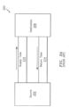
- the fluids are typically conveyed from a fluid source (e.g., an oil tank) 202 to the intended destination (e.g., the bearings or an associated bearing compartment) 206 by a supply tube 210.
- the fluid is then returned from the destination 206 to the source 202 by a return tube 214.
- a closed-loop system 200 is established.
- the tubes may be manufactured as a double walled tube 220, where the fluid is intended to be conveyed by a first tube 232.
- a second tube 236 serves to contain any fluid that may leak from the first tube 232.
- the double walled arrangement 220 shown in FIG. 2B is frequently referred to as a "tube within a tube” as the tube 236 has a larger dimension/diameter than the tube 232 and the tube 232 is contained/nested within the tube 236.
- the tube 232 is an inner tube relative to the outer tube 236.
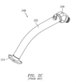
- FIGS. 2C-2D a system assembly 248 incorporating a double walled tube 220 attached to a three-flanged fitting 254 is shown (in FIG. 2C , an attachment of the double walled tube 220 to an angled, threaded fitting 258 is shown for completeness, the details of which are not pertinent to the instant invention), where the fitting 254 itself is formed/fabricated as a unitary piece.
- a brazing operation may be performed and at an interface 266 between the outer tube 236 and the fitting 254 a welding operation may be performed.
- Brazing may be used at the interface 262 to eliminate/minimize the likelihood that a leak path may develop. Also, the use of brazing at the interface 262 may help to keep the inner tube 232 stationary within a seat of the fitting 254.
- Brazing includes strict requirements in terms of coverage and voids. Inspection of a brazed joint can be difficult or time-consuming as x-rays of the joint may be needed. Other difficulties of brazing include the possible rework of the assembly if excess braze is present at the interface 262 (or any other sealing surface). Materials used in brazing include silver braze or gold nickel braze; these materials represent an added cost to the overall construction of the assembly 248. Furthermore, a preparatory step of nickel-flashing (which may include an electrodeposition process) the inner tube 232 and the fitting 254 is performed before the brazing occurs, again representing a cost to the construction of the assembly 248.
- US 2005/212285 A1 discloses a prior art method as set forth in the preamble of claim 1.
- US 2006/061102 A1 , DE 24 58 558 A1 and DE 26 26 813 A1 also disclose prior art systems.
- the method further comprises welding the first tube to a second fitting. In some embodiments, the method further comprises welding the second tube to the second fitting. In some embodiments, the second fitting is an angled, threaded fitting. In some embodiments, the first fitting is a three-flanged fitting.
- the assembly further comprises a second fitting, where a second axial end of the first tube is welded to the second fitting, and where a second axial end of the second tube is welded to the second fitting.
- the assembly further comprises a channel formed in the second sub-fitting coupled to the second tube and a port.
- the channel and the port are configured to convey fluid that is present in a cavity between an inner diameter of the second tube and an outer diameter of the first tube.
- the assembly further comprises a first seal, and a second seal located radially outward of the first seal with respect to a longitudinal axis of the assembly, where the port divides the first seal and the second seal.
- the second sub-fitting includes a divot formed in a surface of the second sub-fitting, where the divot is configured to accommodate a weld torch and provide an area for a weld bead to accumulate.
- the plurality of webs includes three webs. In some embodiments, the webs are substantially equidistantly spaced from one another, center-to-center, and where each of the webs consumes approximately fifty degrees of the overall three hundred sixty degree circumference
- connections are set forth between elements in the following description and in the drawings (the contents of which are included in this disclosure by way of reference). It is noted that these connections are general and, unless specified otherwise, may be direct or indirect and that this specification is not intended to be limiting in this respect.
- a coupling between two or more entities may refer to a direct connection or an indirect connection.
- An indirect connection may incorporate one or more intervening entities.
- apparatuses, systems, and methods are directed to a double walled tube assembly.
- the tube assembly may be formed from a double walled tube and one or more fittings.
- a fitting may be composed of more than one sub-fitting, such as for example a first (inner) tube sub-fitting and a second (outer) tube sub-fitting.
- the tube assembly may be constructed using welding operations. In some embodiments, brazing operations might not be used such that the construction of the tube assembly may be termed to be "braze-free".
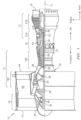
- FIG. 1 is a side cutaway illustration of a geared turbine engine 10.
- This turbine engine 10 extends along an axial centerline 12 between an upstream airflow inlet 14 and a downstream airflow exhaust 16.
- the turbine engine 10 includes a fan section 18, a compressor section 19, a combustor section 20 and a turbine section 21.
- the compressor section 19 includes a low pressure compressor (LPC) section 19A and a high pressure compressor (HPC) section 19B.
- the turbine section 21 includes a high pressure turbine (HPT) section 21A and a low pressure turbine (LPT) section 21B.
- the engine sections 18-21 are arranged sequentially along the centerline 12 within an engine housing 22.
- Each of the engine sections 18-19B, 21A and 21B includes a respective rotor 24-28.
- Each of these rotors 24-28 includes a plurality of rotor blades arranged circumferentially around and connected to one or more respective rotor disks.
- the fan rotor 24 is connected to a gear train 30, for example, through a fan shaft 32.
- the gear train 30 and the LPC rotor 25 are connected to and driven by the LPT rotor 28 through a low speed shaft 33.
- the HPC rotor 26 is connected to and driven by the HPT rotor 27 through a high speed shaft 34.
- the shafts 32-34 are rotatably supported by a plurality of bearings 36; e.g., rolling element and/or thrust bearings. Each of these bearings 36 is connected to the engine housing 22 by at least one stationary structure such as, for example, an annular support strut.
- the air within the core gas path 38 may be referred to as "core air”.
- the air within the bypass gas path 40 may be referred to as "bypass air”.
- the core air is directed through the engine sections 19-21, and exits the turbine engine 10 through the airflow exhaust 16 to provide forward engine thrust.
- fuel is injected into a combustion chamber 42 and mixed with compressed core air. This fuel-core air mixture is ignited to power the turbine engine 10.
- the bypass air is directed through the bypass gas path 40 and out of the turbine engine 10 through a bypass nozzle 44 to provide additional forward engine thrust. This additional forward engine thrust may account for a majority (e.g., more than 70 percent) of total engine thrust.
- at least some of the bypass air may be directed out of the turbine engine 10 through a thrust reverser to provide reverse engine thrust.
- FIG. 1 represents one possible configuration for an engine 10. Aspects of the invention may be applied in connection with other environments, including additional configurations for gas turbine engines. Aspects of the invention may be applied in connection with non-geared engines.
- the multi-piece fitting 354 may include an inner tube fitting 372 and an outer tube fitting 376.
- the outer tube fitting 376 may radially surround the inner tube fitting 372, such that the inner tube fitting 372 is co-axially seated within the outer tube fitting 376.
- the multi-piece fitting 354 is not a unitary piece. Instead, the fitting 354 is comprised of sub-fittings 372 and 376.
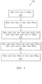
- the method 500 may be used to construct an assembly, such as for example an assembly incorporating a double walled tube with one or more axially attached fittings.
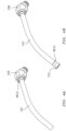
- a first axial end of an inner tube 432 (which may correspond to the inner tube 232 of FIG. 2B ) may be welded to a fitting 258 (see FIG. 4A ).
- the first axial end of the inner tube 432 may abut the fitting 258 such that the weld may occur where they abut.
- a second axial end of the inner tube 432 may be welded to an inner tube fitting 372 (see FIG. 4B ).
- the second axial end of the inner tube 432 may abut the fitting 372 such that the weld may occur where they abut.
- an outer tube 436 (which may correspond to the outer tube 236 of FIG. 2B ) may be slid over the inner tube fitting 372 and the inner tube 432 and a first axial end of the outer tube 436 may be welded to the fitting 258 (see FIG. 4C ).
- an outer tube fitting 376 may be slid over the inner tube fitting 372 (see FIG. 4D ) such that the outer tube fitting 376 substantially radially surrounds the interior flow path of the inner tube fitting.
- the inner and outer tube fittings 372, 376 are coaxial.
- a second axial end of the outer tube 436 may be welded to the outer tube fitting 376.
- the outer tube fitting 376 and the inner tube fitting 372 may be welded to one another (see FIG. 4E ).
- the welding of block 542 may be "filler-free" in the sense that, in some embodiments, no additional filler material may be introduced as part of block 542.
- the mating faces 372a and 376a of the inner tube fitting 372 and the outer tube fitting 376, respectively, may be arranged/oriented to facilitate the welding operation of block 542.
- the fitting 354 may be termed a "triple-welded" fitting, as the assembly resulting from the construction may incorporate three welding operations with respect to the fitting 354 (e.g., blocks 512, 532, and 542).
- FIG. 6 illustrates an example of such an embodiment.
- an inner seal 612 and an outer seal 616 are shown as having been coupled to the inner tube fitting 372 and the outer tube fitting 376.
- the seals 612 and 616 may be made of one or more materials, e.g., rubber.
- the seals 612 and 616 may provide for additional fluid retention capabilities in the event that, e.g., one or more of the weld operations described above in connection with FIG. 5 is compromised.
- FIG. 6 also shows a channel 626 formed in the outer tube fitting 376 leading to a port 646.
- the channel 626 and the port 646 may be configured to convey/drain any (leaking) fluid that may be present in a cavity 640 between an inner diameter of the outer tube 436 and an outer diameter of the inner tube 432.
- the port 646 may bisect/divide the seals 612 and 616 from one another. While described as multiple seals 612 and 616, the seals 612 and 616 may be a unitary piece in some embodiments.
- an outer tube fitting 776 is shown which falls outside the wording of the claims.
- the outer tube fitting 776 is similar to the outer tube fitting 376 of FIG. 3C and may be included as a part of a double-walled tube assembly in a manner similar to what is described above.
- the outer tube fitting 776 may include a recess/divot 786 formed in a surface of the outer tube fitting 776.
- the divot 786 may provide additional space to seat/accommodate a weld torch during an assembly procedure, such as for example the method 500 described above (see FIG. 5 ). This additional space may provide an area for a weld bead to accumulate and may limit interference with a packing seal.
- FIG. 8 illustrates the outer tube fitting 776 (and associated divot 786) in conjunction with the inner tube fitting 372.
- an outer tube fitting 976 is shown.
- the outer tube fitting 976 is similar to the outer tube fitting 376 of FIG. 3C and the outer tube fitting 776 of FIG. 7 and may be included as a part of a double-walled tube assembly in a manner similar to what is described above.
- the outer tube fitting 976 includes a weld lip/web-based design incorporated into a drain channel/port (e.g., channel 626/port 646 of FIG. 6 ). More specifically, as shown in FIG. 9 , weld lips/webs 986 are present at various circumferential locations (potentially equidistantly spaced, center-to-center) along a surface of the outer tube fitting 976.
- Each weld lip/web 986 consumes a portion of the overall three hundred sixty degree circumference. For example, each weld lip/web 986 may consume approximately fifty degrees.
- the weld lips/webs 986 may allow for less heat due to the weld not having to be continuous. Less heat means less potential for weld distortion of fittings and sealing surface(s) of fittings.
- FIG. 10 illustrates another view of the outer tube fitting 976 (and associated weld lips/webs 986).
- a tube assembly in accordance with aspects of this invention is also less complex in terms of the construction of the tube assembly. Brazing operations may be minimized/eliminated thereby reducing the manufacturing costs associated with, e.g., material costs, pre/post brazing operations, inspections, etc.
Landscapes
- Engineering & Computer Science (AREA)
- General Engineering & Computer Science (AREA)
- Mechanical Engineering (AREA)
- Butt Welding And Welding Of Specific Article (AREA)
- Rigid Pipes And Flexible Pipes (AREA)
- Heat-Exchange Devices With Radiators And Conduit Assemblies (AREA)
Description
- Gas turbine engines, such as those which power aircraft and industrial equipment, employ a compressor to compress air that is drawn into the engine and a turbine to capture energy associated with the combustion of a fuel-air mixture. One or more fluids are typically circulated throughout the engine. For example, oil may be supplied to one or more bearings in order to clean, cool, and lubricate the bearings.
- Referring to
FIG. 2A , the fluids are typically conveyed from a fluid source (e.g., an oil tank) 202 to the intended destination (e.g., the bearings or an associated bearing compartment) 206 by asupply tube 210. The fluid is then returned from thedestination 206 to the source 202 by areturn tube 214. In this manner, a closed-loop system 200 is established. There may be other components included; thesystem 200 is simplified for the sake of explanation and illustrative convenience. These other components may include additional tubes beyond thetubes - Referring to
FIG. 2B , in order to enhance reliability and avoid a leak impacting the performance/operability of the engine, the tubes (e.g., thetube 210 or the tube 214) may be manufactured as a doublewalled tube 220, where the fluid is intended to be conveyed by afirst tube 232. Asecond tube 236 serves to contain any fluid that may leak from thefirst tube 232. The double walledarrangement 220 shown inFIG. 2B is frequently referred to as a "tube within a tube" as thetube 236 has a larger dimension/diameter than thetube 232 and thetube 232 is contained/nested within thetube 236. In this respect, thetube 232 is an inner tube relative to theouter tube 236. - Referring to
FIGS. 2C-2D , asystem assembly 248 incorporating a double walledtube 220 attached to a three-flangedfitting 254 is shown (inFIG. 2C , an attachment of the double walledtube 220 to an angled, threadedfitting 258 is shown for completeness, the details of which are not pertinent to the instant invention), where thefitting 254 itself is formed/fabricated as a unitary piece. At aninterface 262 between theinner tube 232 and the fitting 254 a brazing operation may be performed and at aninterface 266 between theouter tube 236 and the fitting 254 a welding operation may be performed. Brazing may be used at theinterface 262 to eliminate/minimize the likelihood that a leak path may develop. Also, the use of brazing at theinterface 262 may help to keep theinner tube 232 stationary within a seat of thefitting 254. - Brazing includes strict requirements in terms of coverage and voids. Inspection of a brazed joint can be difficult or time-consuming as x-rays of the joint may be needed. Other difficulties of brazing include the possible rework of the assembly if excess braze is present at the interface 262 (or any other sealing surface). Materials used in brazing include silver braze or gold nickel braze; these materials represent an added cost to the overall construction of the
assembly 248. Furthermore, a preparatory step of nickel-flashing (which may include an electrodeposition process) theinner tube 232 and thefitting 254 is performed before the brazing occurs, again representing a cost to the construction of theassembly 248. -
US 2005/212285 A1 discloses a prior art method as set forth in the preamble of claim 1.US 2006/061102 A1 ,DE 24 58 558 A1 andDE 26 26 813 A1 also disclose prior art systems. - The following presents a simplified summary in order to provide a basic understanding of some aspects of the invention. The summary is not an extensive overview of the invention. It is neither intended to identify key or critical elements of the invention nor to delineate the scope of the invention. The following summary merely presents some concepts of the invention in a simplified form as a prelude to the description below.
- According to the present invention, there is provided a method for constructing a double walled tube assembly as set forth in claim 1.
- In some embodiments, the method further comprises welding the first tube to a second fitting. In some embodiments, the method further comprises welding the second tube to the second fitting. In some embodiments, the second fitting is an angled, threaded fitting. In some embodiments, the first fitting is a three-flanged fitting.
- There is further provided an assembly according to claim 6.
- In some embodiments, the assembly further comprises a second fitting, where a second axial end of the first tube is welded to the second fitting, and where a second axial end of the second tube is welded to the second fitting. In some embodiments, the assembly further comprises a channel formed in the second sub-fitting coupled to the second tube and a port. In some embodiments, the channel and the port are configured to convey fluid that is present in a cavity between an inner diameter of the second tube and an outer diameter of the first tube. In some embodiments, the assembly further comprises a first seal, and a second seal located radially outward of the first seal with respect to a longitudinal axis of the assembly, where the port divides the first seal and the second seal. In some embodiments, at least one of the first seal or the second seal is made of at least rubber. In some embodiments, the second sub-fitting includes a divot formed in a surface of the second sub-fitting, where the divot is configured to accommodate a weld torch and provide an area for a weld bead to accumulate. In some embodiments, the plurality of webs includes three webs. In some embodiments, the webs are substantially equidistantly spaced from one another, center-to-center, and where each of the webs consumes approximately fifty degrees of the overall three hundred sixty degree circumference
- The present invention is illustrated by way of example and not limited in the accompanying figures in which like reference numerals indicate similar elements. The drawings are not necessarily drawn to scale unless specifically indicated otherwise.
-
FIG. 1 is a side cutaway illustration of a geared turbine engine. -
FIG. 2A illustrates a prior art system for circulating a fluid. -
FIG. 2B illustrates a prior art double walled tube. -
FIG. 2C illustrates a prior art system assembly incorporating a double walled tube and fittings. -
FIG. 2D illustrates an interface between the double walled tube and a fitting of the system ofFIG. 2C . -
FIG. 3A illustrates a fitting in accordance with aspects of this invention. -
FIG. 3B illustrates an inner tube fitting of the fitting ofFIG. 3A . -
FIG. 3C illustrates an outer tube fitting of the fitting ofFIG. 3A . -
FIGS. 4A-4E illustrate various welding operations being performed in the constructions of a double walled tube assembly. -
FIG. 5 illustrates a flow chart of a method for constructing a double walled tube assembly in accordance with aspects of this invention. -
FIG. 6 illustrates a fitting coupled to one or more seals in accordance with aspects of this invention. -
FIG. 7 illustrates an outer tube fitting that incorporates a divot. -
FIG. 8 illustrates the outer tube fitting ofFIG. 7 in relation to an inner tube fitting. -
FIG. 9 illustrates an outer tube fitting that incorporates one or more weld lips in accordance with aspects of this invention. -
FIG. 10 illustrates another view of the outer tube fitting ofFIG. 9 . - It is noted that various connections are set forth between elements in the following description and in the drawings (the contents of which are included in this disclosure by way of reference). It is noted that these connections are general and, unless specified otherwise, may be direct or indirect and that this specification is not intended to be limiting in this respect. A coupling between two or more entities may refer to a direct connection or an indirect connection. An indirect connection may incorporate one or more intervening entities.
- In accordance with aspects of the invention, apparatuses, systems, and methods are directed to a double walled tube assembly. The tube assembly may be formed from a double walled tube and one or more fittings. In some embodiments, a fitting may be composed of more than one sub-fitting, such as for example a first (inner) tube sub-fitting and a second (outer) tube sub-fitting. The tube assembly may be constructed using welding operations. In some embodiments, brazing operations might not be used such that the construction of the tube assembly may be termed to be "braze-free".
- Aspects of the invention may be applied in connection with a gas turbine engine.
FIG. 1 is a side cutaway illustration of a gearedturbine engine 10. Thisturbine engine 10 extends along anaxial centerline 12 between anupstream airflow inlet 14 and adownstream airflow exhaust 16. Theturbine engine 10 includes afan section 18, acompressor section 19, acombustor section 20 and aturbine section 21. Thecompressor section 19 includes a low pressure compressor (LPC)section 19A and a high pressure compressor (HPC) section 19B. Theturbine section 21 includes a high pressure turbine (HPT)section 21A and a low pressure turbine (LPT)section 21B. - The engine sections 18-21 are arranged sequentially along the
centerline 12 within anengine housing 22. Each of the engine sections 18-19B, 21A and 21B includes a respective rotor 24-28. Each of these rotors 24-28 includes a plurality of rotor blades arranged circumferentially around and connected to one or more respective rotor disks. - The
fan rotor 24 is connected to agear train 30, for example, through afan shaft 32. Thegear train 30 and theLPC rotor 25 are connected to and driven by theLPT rotor 28 through alow speed shaft 33. TheHPC rotor 26 is connected to and driven by theHPT rotor 27 through ahigh speed shaft 34. The shafts 32-34 are rotatably supported by a plurality ofbearings 36; e.g., rolling element and/or thrust bearings. Each of thesebearings 36 is connected to theengine housing 22 by at least one stationary structure such as, for example, an annular support strut. - During operation, air enters the
turbine engine 10 through theairflow inlet 14, and is directed through thefan section 18 and into acore gas path 38 and abypass gas path 40. The air within thecore gas path 38 may be referred to as "core air". The air within thebypass gas path 40 may be referred to as "bypass air". The core air is directed through the engine sections 19-21, and exits theturbine engine 10 through theairflow exhaust 16 to provide forward engine thrust. Within thecombustor section 20, fuel is injected into acombustion chamber 42 and mixed with compressed core air. This fuel-core air mixture is ignited to power theturbine engine 10. The bypass air is directed through thebypass gas path 40 and out of theturbine engine 10 through abypass nozzle 44 to provide additional forward engine thrust. This additional forward engine thrust may account for a majority (e.g., more than 70 percent) of total engine thrust. Alternatively, at least some of the bypass air may be directed out of theturbine engine 10 through a thrust reverser to provide reverse engine thrust. -
FIG. 1 represents one possible configuration for anengine 10. Aspects of the invention may be applied in connection with other environments, including additional configurations for gas turbine engines. Aspects of the invention may be applied in connection with non-geared engines. - Referring now to
FIGS. 3A amulti-piece fitting 354 is shown. As shown inFIGS. 3A-3C , the multi-piece fitting 354 may include an inner tube fitting 372 and an outer tube fitting 376. As shown inFIG. 3A , the outer tube fitting 376 may radially surround the inner tube fitting 372, such that the inner tube fitting 372 is co-axially seated within the outer tube fitting 376. Thus, unlike the fitting 254 ofFIGS. 2C-2D , the multi-piece fitting 354 is not a unitary piece. Instead, the fitting 354 is comprised ofsub-fittings - Referring now to
FIG. 5 (in view ofFIGS. 4A-4E ), a flowchart of amethod 500 is shown. Themethod 500 may be used to construct an assembly, such as for example an assembly incorporating a double walled tube with one or more axially attached fittings. - In
block 502, a first axial end of an inner tube 432 (which may correspond to theinner tube 232 ofFIG. 2B ) may be welded to a fitting 258 (seeFIG. 4A ). The first axial end of theinner tube 432 may abut the fitting 258 such that the weld may occur where they abut. - In
block 512, a second axial end of theinner tube 432 may be welded to an inner tube fitting 372 (seeFIG. 4B ). The second axial end of theinner tube 432 may abut the fitting 372 such that the weld may occur where they abut. - In
block 522, an outer tube 436 (which may correspond to theouter tube 236 ofFIG. 2B ) may be slid over the inner tube fitting 372 and theinner tube 432 and a first axial end of theouter tube 436 may be welded to the fitting 258 (seeFIG. 4C ). - In
block 532, an outer tube fitting 376 may be slid over the inner tube fitting 372 (seeFIG. 4D ) such that the outer tube fitting 376 substantially radially surrounds the interior flow path of the inner tube fitting. The inner andouter tube fittings block 532, a second axial end of theouter tube 436 may be welded to the outer tube fitting 376. - In
block 542, the outer tube fitting 376 and the inner tube fitting 372 may be welded to one another (seeFIG. 4E ). The welding ofblock 542 may be "filler-free" in the sense that, in some embodiments, no additional filler material may be introduced as part ofblock 542. The mating faces 372a and 376a of the inner tube fitting 372 and the outer tube fitting 376, respectively, may be arranged/oriented to facilitate the welding operation ofblock 542. - As described above in relation to
FIGS. 3A-3C ,4A-4E , and5 , the fitting 354 may be termed a "triple-welded" fitting, as the assembly resulting from the construction may incorporate three welding operations with respect to the fitting 354 (e.g., blocks 512, 532, and 542). - In some embodiments, it may be desirable/required to enhance the sealing capability associated with a double walled tube assembly.
FIG. 6 illustrates an example of such an embodiment. As shown inFIG. 6 , aninner seal 612 and anouter seal 616 are shown as having been coupled to the inner tube fitting 372 and the outer tube fitting 376. Theseals seals FIG. 5 is compromised.FIG. 6 also shows achannel 626 formed in the outer tube fitting 376 leading to aport 646. Thechannel 626 and theport 646 may be configured to convey/drain any (leaking) fluid that may be present in acavity 640 between an inner diameter of theouter tube 436 and an outer diameter of theinner tube 432. Theport 646 may bisect/divide theseals multiple seals seals - Referring to
FIG. 7 , an outer tube fitting 776 is shown which falls outside the wording of the claims. The outer tube fitting 776 is similar to the outer tube fitting 376 ofFIG. 3C and may be included as a part of a double-walled tube assembly in a manner similar to what is described above. The outer tube fitting 776 may include a recess/divot 786 formed in a surface of the outer tube fitting 776. Thedivot 786 may provide additional space to seat/accommodate a weld torch during an assembly procedure, such as for example themethod 500 described above (seeFIG. 5 ). This additional space may provide an area for a weld bead to accumulate and may limit interference with a packing seal.FIG. 8 illustrates the outer tube fitting 776 (and associated divot 786) in conjunction with the inner tube fitting 372. - Referring to
FIG. 9 , an outer tube fitting 976 is shown. The outer tube fitting 976 is similar to the outer tube fitting 376 ofFIG. 3C and the outer tube fitting 776 ofFIG. 7 and may be included as a part of a double-walled tube assembly in a manner similar to what is described above. The outer tube fitting 976 includes a weld lip/web-based design incorporated into a drain channel/port (e.g.,channel 626/port 646 ofFIG. 6 ). More specifically, as shown inFIG. 9 , weld lips/webs 986 are present at various circumferential locations (potentially equidistantly spaced, center-to-center) along a surface of the outer tube fitting 976. Each weld lip/web 986 consumes a portion of the overall three hundred sixty degree circumference. For example, each weld lip/web 986 may consume approximately fifty degrees. The weld lips/webs 986 may allow for less heat due to the weld not having to be continuous. Less heat means less potential for weld distortion of fittings and sealing surface(s) of fittings.FIG. 10 illustrates another view of the outer tube fitting 976 (and associated weld lips/webs 986). - Technical effects and benefits of this invention include a tube assembly that is less susceptible to leaking fluid relative to conventional tube assemblies. A tube assembly in accordance with aspects of this invention is also less complex in terms of the construction of the tube assembly. Brazing operations may be minimized/eliminated thereby reducing the manufacturing costs associated with, e.g., material costs, pre/post brazing operations, inspections, etc.
Claims (14)
- A method for constructing a double walled tube assembly, comprising:welding a first axial end of a first tube (432) to a first sub-fitting (372) of a first fitting (354);sliding a second tube (436) over the first sub-fitting (372) and the first tube (432);sliding a second sub-fitting (376;776;976) of the first fitting (354) over the first sub-fitting (372) such that the first and second sub-fittings (372;376;776;976) are co-axial;welding a first axial end of the second tube (436) to the second sub-fitting (376;776;976); andwelding the second sub-fitting (376;776;976) to the first sub-fitting (372);characterised in that:
the second sub-fitting (376;776;976) includes a plurality of weld lips or webs (986) formed at various circumferential locations along a surface of the second sub-fitting (376;776;976), wherein each weld lip or web of the plurality of weld lips or webs (986) consumes a portion of the overall three hundred sixty degree circumference. - The method of claim 1, further comprising:
welding the first tube (432) to a second fitting (258). - The method of claim 2, further comprising:
welding the second tube (436) to the second fitting (258). - The method of claim 2 or 3, wherein the second fitting (258) is an angled, threaded fitting.
- The method of any preceding claim, wherein the first fitting (354) is a three-flanged fitting.
- An assembly, comprising:a first fitting (354) that includes a first sub-fitting (372) and a second sub-fitting (376;776;976);a first tube (432) having a first axial end that is welded to the first sub-fitting (372); anda second tube (436) having a first axial end that is welded to the second sub-fitting (376;776;976),wherein the first tube (432) is nested within the second tube (436),wherein the first sub-fitting (372) is welded to the second sub-fitting (376;776;976)characterised in that:
the second sub-fitting (376;776;976) includes a plurality of weld lips or webs (986) formed at various circumferential locations along a surface of the second sub-fitting (376;776;976), wherein each weld lip or web of the plurality of weld lips or webs (986) consumes a portion of the overall three hundred sixty degree circumference. - The assembly of claim 6, further comprising:a second fitting (258),wherein a second axial end of the first tube (432) is welded to the second fitting (258), andwherein a second axial end of the second tube (436) is welded to the second fitting (258).
- The assembly of claim 6 or 7, further comprising:
a channel (626) formed in the second sub-fitting (376;776;976) coupled to the second tube (436) and a port (646). - The assembly of claim 8, wherein the channel (626) and the port (646) are configured to convey fluid that is present in a cavity between an inner diameter of the second tube (436) and an outer diameter of the first tube (432).
- The assembly of claim 8 or 9, further comprising:a first seal (612); anda second seal (616) located radially outward of the first seal (612) with respect to a longitudinal axis of the assembly,wherein the port (646) divides the first seal (612) and the second seal (616).
- The assembly of claim 10, wherein at least one of the first seal (612) or the second seal (616) is made of at least rubber.
- The assembly of any of claims 6 to 11, wherein the second sub-fitting (376;776;976) includes a divot (786) formed in a surface of the second sub-fitting (376;776;976), wherein the divot (786) is configured to accommodate a weld torch and provide an area for a weld bead to accumulate.
- The assembly or method of any preceding claim, wherein the plurality of weld lips or webs (986) includes three webs.
- The assembly or method of any preceding claim, wherein the weld lips or webs (986) are substantially equidistantly spaced from one another, center-to-center, and wherein each of the weld lips or webs (986) consumes approximately fifty degrees of the overall three hundred sixty degree circumference.
Applications Claiming Priority (1)
| Application Number | Priority Date | Filing Date | Title |
|---|---|---|---|
| US15/255,813 US10627033B2 (en) | 2016-09-02 | 2016-09-02 | Triple-weld fitting |
Publications (2)
| Publication Number | Publication Date |
|---|---|
| EP3296053A1 EP3296053A1 (en) | 2018-03-21 |
| EP3296053B1 true EP3296053B1 (en) | 2024-11-20 |
Family
ID=59790974
Family Applications (1)
| Application Number | Title | Priority Date | Filing Date |
|---|---|---|---|
| EP17189280.5A Active EP3296053B1 (en) | 2016-09-02 | 2017-09-04 | Triple-weld fitting |
Country Status (2)
| Country | Link |
|---|---|
| US (1) | US10627033B2 (en) |
| EP (1) | EP3296053B1 (en) |
Families Citing this family (5)
| Publication number | Priority date | Publication date | Assignee | Title |
|---|---|---|---|---|
| WO2019222306A2 (en) * | 2018-05-15 | 2019-11-21 | Cummins Inc. | Dual-wall integrated flange joint |
| CN109332977B (en) * | 2018-11-26 | 2021-01-01 | 中国航发南方工业有限公司 | Clamping device and welding method for labyrinth sealing assembly |
| GB2580037B (en) * | 2018-12-19 | 2021-04-28 | Gkn Aerospace Sweden Ab | Anti-coking |
| US11660711B2 (en) * | 2019-06-06 | 2023-05-30 | Raytheon Technologies Corporation | Radially outward orbital welding technique as a joining method used for inner tube to fitting connections in double wall tube configurations |
| US12637963B1 (en) * | 2025-04-02 | 2026-05-26 | Rtx Corporation | Maintainable design for bearing compartment service line incorporating a grooved end |
Family Cites Families (24)
| Publication number | Priority date | Publication date | Assignee | Title |
|---|---|---|---|---|
| US2045493A (en) | 1932-12-14 | 1936-06-23 | Gen Electric | Welded frame for combustion engines |
| US2763923A (en) | 1951-06-27 | 1956-09-25 | Babcock & Wilcox Co | Method of and transition member for weld uniting dissimilar metals |
| US3079179A (en) | 1960-12-23 | 1963-02-26 | Hubert R Niemoth | Coaxial tube coupling |
| US3254404A (en) | 1962-03-19 | 1966-06-07 | Dana Corp | Method for butt welding |
| DE2046331A1 (en) | 1970-09-21 | 1972-03-23 | Kabel Metallwerke Ghh | Method for connecting coaxial Rohrsy stars |
| DE2458558A1 (en) | 1974-12-11 | 1976-06-16 | Wilhelm Schulz | Flange for heated or cooled pipe lines - has twin concentric tubular construction accommodating change of section jointing piece |
| NZ184196A (en) * | 1976-05-27 | 1981-01-23 | Tokan Kogyo Co Ltd | Thermoplastic multi-walled pipes and method of joining same to single walled thermoplastic pipe |
| DE2626813C3 (en) | 1976-06-15 | 1980-10-30 | Bayer Ag, 5090 Leverkusen | Process for the production of detachable connections in a jacket-heated pipe system |
| NL8300207A (en) | 1983-01-20 | 1984-08-16 | Berg A P Ingbureau | DEVICE FOR WELDING TUBES. |
| US5129444A (en) | 1989-06-30 | 1992-07-14 | Wagner Castings Company | Method of placing fluid passage tubing in cast products |
| US5088774A (en) | 1990-05-07 | 1992-02-18 | Tylan General, Inc. | Coupling for interconnection of coaxial tubing |
| DE10057031C1 (en) | 2000-11-17 | 2002-05-23 | Werner Jankus | Device for the inner centering of pipe joints to be welded together |
| US20050212285A1 (en) | 2004-03-29 | 2005-09-29 | Ope International, L.P. | Dual-walled piping system and methods |
| US7226089B2 (en) | 2004-09-21 | 2007-06-05 | Wilkinson Iii Joseph | Jacketed pipe flange |
| US8122721B2 (en) | 2006-01-04 | 2012-02-28 | General Electric Company | Combustion turbine engine and methods of assembly |
| US7687928B2 (en) | 2006-06-14 | 2010-03-30 | Smiths Aerospace, Llc | Dual-structured aircraft engine starter/generator |
| KR20100046104A (en) * | 2007-08-27 | 2010-05-06 | 노라 엔지니어링 가부시키가이샤 | Loose flange pipe joint |
| US8596959B2 (en) | 2009-10-09 | 2013-12-03 | Pratt & Whitney Canada Corp. | Oil tube with integrated heat shield |
| DE102009057954A1 (en) | 2009-12-11 | 2011-06-16 | GM Global Technology Operations LLC, ( n. d. Ges. d. Staates Delaware ), Detroit | Connection device for a coaxial tube heat exchanger |
| GB201103317D0 (en) | 2011-02-28 | 2011-04-13 | Rolls Royce Plc | |
| WO2013052741A2 (en) * | 2011-10-07 | 2013-04-11 | Eaton Corporation | Double wall tube adapter and joint |
| US10196935B2 (en) | 2012-04-27 | 2019-02-05 | General Electric Company | Half-spoolie metal seal integral with tube |
| US20150219263A1 (en) | 2014-02-03 | 2015-08-06 | Electro-Motive Diesel, Inc. | Flange and Adapter for Dual-Walled Tube Assembly |
| US9982821B1 (en) | 2015-01-28 | 2018-05-29 | United Technologies Corporation | Doubled wall pipe flange and coupling configuration |
-
2016
- 2016-09-02 US US15/255,813 patent/US10627033B2/en active Active
-
2017
- 2017-09-04 EP EP17189280.5A patent/EP3296053B1/en active Active
Also Published As
| Publication number | Publication date |
|---|---|
| US10627033B2 (en) | 2020-04-21 |
| EP3296053A1 (en) | 2018-03-21 |
| US20180066781A1 (en) | 2018-03-08 |
Similar Documents
| Publication | Publication Date | Title |
|---|---|---|
| CA2715600C (en) | Oil tube with integrated heat shield | |
| US10815898B2 (en) | Seal assembly for a static structure of a gas turbine engine | |
| EP3358139B1 (en) | Threaded fitting for tube | |
| EP3296053A1 (en) | Triple-weld fitting | |
| EP3730743B1 (en) | Multiwall tube and fitting for bearing oil supply | |
| EP3255326B1 (en) | Double walled tube and manufacture thereof | |
| EP3358140B1 (en) | Fitting for multiwall tube | |
| US20170362949A1 (en) | Carbon seal spring assembly | |
| US20140091535A1 (en) | Piston ring coated carbon seal | |
| EP3318722B1 (en) | Seal assembly for a rotatable component | |
| EP3967855B1 (en) | Boss for gas turbine engine | |
| US10781718B1 (en) | Seal plate lubricant slinger | |
| EP3051198A1 (en) | Doubled wall pipe flange and coupling configuration | |
| US11660711B2 (en) | Radially outward orbital welding technique as a joining method used for inner tube to fitting connections in double wall tube configurations | |
| EP3189922B1 (en) | Advanced braze joint for tube-to-tube connection | |
| US10767867B2 (en) | Bearing support assembly | |
| US20220389820A1 (en) | Anti-vortex tube retaining ring and bore basket | |
| EP3418501B1 (en) | Seal and corresponding system for reducing leakage about a rotating shaft | |
| US11578829B2 (en) | Middle threaded fitting |
Legal Events
| Date | Code | Title | Description |
|---|---|---|---|
| PUAI | Public reference made under article 153(3) epc to a published international application that has entered the european phase |
Free format text: ORIGINAL CODE: 0009012 |
|
| STAA | Information on the status of an ep patent application or granted ep patent |
Free format text: STATUS: THE APPLICATION HAS BEEN PUBLISHED |
|
| AK | Designated contracting states |
Kind code of ref document: A1 Designated state(s): AL AT BE BG CH CY CZ DE DK EE ES FI FR GB GR HR HU IE IS IT LI LT LU LV MC MK MT NL NO PL PT RO RS SE SI SK SM TR |
|
| AX | Request for extension of the european patent |
Extension state: BA ME |
|
| STAA | Information on the status of an ep patent application or granted ep patent |
Free format text: STATUS: REQUEST FOR EXAMINATION WAS MADE |
|
| 17P | Request for examination filed |
Effective date: 20180921 |
|
| RBV | Designated contracting states (corrected) |
Designated state(s): AL AT BE BG CH CY CZ DE DK EE ES FI FR GB GR HR HU IE IS IT LI LT LU LV MC MK MT NL NO PL PT RO RS SE SI SK SM TR |
|
| RAP1 | Party data changed (applicant data changed or rights of an application transferred) |
Owner name: RAYTHEON TECHNOLOGIES CORPORATION |
|
| STAA | Information on the status of an ep patent application or granted ep patent |
Free format text: STATUS: EXAMINATION IS IN PROGRESS |
|
| 17Q | First examination report despatched |
Effective date: 20210520 |
|
| RAP3 | Party data changed (applicant data changed or rights of an application transferred) |
Owner name: RTX CORPORATION |
|
| GRAP | Despatch of communication of intention to grant a patent |
Free format text: ORIGINAL CODE: EPIDOSNIGR1 |
|
| STAA | Information on the status of an ep patent application or granted ep patent |
Free format text: STATUS: GRANT OF PATENT IS INTENDED |
|
| RIC1 | Information provided on ipc code assigned before grant |
Ipc: F16L 23/026 20060101ALI20240514BHEP Ipc: F16L 39/00 20060101ALI20240514BHEP Ipc: B23K 31/02 20060101AFI20240514BHEP |
|
| INTG | Intention to grant announced |
Effective date: 20240613 |
|
| GRAS | Grant fee paid |
Free format text: ORIGINAL CODE: EPIDOSNIGR3 |
|
| GRAA | (expected) grant |
Free format text: ORIGINAL CODE: 0009210 |
|
| STAA | Information on the status of an ep patent application or granted ep patent |
Free format text: STATUS: THE PATENT HAS BEEN GRANTED |
|
| AK | Designated contracting states |
Kind code of ref document: B1 Designated state(s): AL AT BE BG CH CY CZ DE DK EE ES FI FR GB GR HR HU IE IS IT LI LT LU LV MC MK MT NL NO PL PT RO RS SE SI SK SM TR |
|
| REG | Reference to a national code |
Ref country code: GB Ref legal event code: FG4D |
|
| REG | Reference to a national code |
Ref country code: CH Ref legal event code: EP |
|
| REG | Reference to a national code |
Ref country code: DE Ref legal event code: R096 Ref document number: 602017086201 Country of ref document: DE |
|
| REG | Reference to a national code |
Ref country code: IE Ref legal event code: FG4D |
|
| REG | Reference to a national code |
Ref country code: LT Ref legal event code: MG9D |
|
| REG | Reference to a national code |
Ref country code: NL Ref legal event code: MP Effective date: 20241120 |
|
| PG25 | Lapsed in a contracting state [announced via postgrant information from national office to epo] |
Ref country code: IS Free format text: LAPSE BECAUSE OF FAILURE TO SUBMIT A TRANSLATION OF THE DESCRIPTION OR TO PAY THE FEE WITHIN THE PRESCRIBED TIME-LIMIT Effective date: 20250320 Ref country code: HR Free format text: LAPSE BECAUSE OF FAILURE TO SUBMIT A TRANSLATION OF THE DESCRIPTION OR TO PAY THE FEE WITHIN THE PRESCRIBED TIME-LIMIT Effective date: 20241120 Ref country code: PT Free format text: LAPSE BECAUSE OF FAILURE TO SUBMIT A TRANSLATION OF THE DESCRIPTION OR TO PAY THE FEE WITHIN THE PRESCRIBED TIME-LIMIT Effective date: 20250320 |
|
| PG25 | Lapsed in a contracting state [announced via postgrant information from national office to epo] |
Ref country code: NL Free format text: LAPSE BECAUSE OF FAILURE TO SUBMIT A TRANSLATION OF THE DESCRIPTION OR TO PAY THE FEE WITHIN THE PRESCRIBED TIME-LIMIT Effective date: 20241120 Ref country code: FI Free format text: LAPSE BECAUSE OF FAILURE TO SUBMIT A TRANSLATION OF THE DESCRIPTION OR TO PAY THE FEE WITHIN THE PRESCRIBED TIME-LIMIT Effective date: 20241120 |
|
| REG | Reference to a national code |
Ref country code: AT Ref legal event code: MK05 Ref document number: 1743152 Country of ref document: AT Kind code of ref document: T Effective date: 20241120 |
|
| PG25 | Lapsed in a contracting state [announced via postgrant information from national office to epo] |
Ref country code: BG Free format text: LAPSE BECAUSE OF FAILURE TO SUBMIT A TRANSLATION OF THE DESCRIPTION OR TO PAY THE FEE WITHIN THE PRESCRIBED TIME-LIMIT Effective date: 20241120 |
|
| PG25 | Lapsed in a contracting state [announced via postgrant information from national office to epo] |
Ref country code: ES Free format text: LAPSE BECAUSE OF FAILURE TO SUBMIT A TRANSLATION OF THE DESCRIPTION OR TO PAY THE FEE WITHIN THE PRESCRIBED TIME-LIMIT Effective date: 20241120 |
|
| PG25 | Lapsed in a contracting state [announced via postgrant information from national office to epo] |
Ref country code: NO Free format text: LAPSE BECAUSE OF FAILURE TO SUBMIT A TRANSLATION OF THE DESCRIPTION OR TO PAY THE FEE WITHIN THE PRESCRIBED TIME-LIMIT Effective date: 20250220 |
|
| PG25 | Lapsed in a contracting state [announced via postgrant information from national office to epo] |
Ref country code: LV Free format text: LAPSE BECAUSE OF FAILURE TO SUBMIT A TRANSLATION OF THE DESCRIPTION OR TO PAY THE FEE WITHIN THE PRESCRIBED TIME-LIMIT Effective date: 20241120 Ref country code: GR Free format text: LAPSE BECAUSE OF FAILURE TO SUBMIT A TRANSLATION OF THE DESCRIPTION OR TO PAY THE FEE WITHIN THE PRESCRIBED TIME-LIMIT Effective date: 20250221 Ref country code: AT Free format text: LAPSE BECAUSE OF FAILURE TO SUBMIT A TRANSLATION OF THE DESCRIPTION OR TO PAY THE FEE WITHIN THE PRESCRIBED TIME-LIMIT Effective date: 20241120 |
|
| PG25 | Lapsed in a contracting state [announced via postgrant information from national office to epo] |
Ref country code: PL Free format text: LAPSE BECAUSE OF FAILURE TO SUBMIT A TRANSLATION OF THE DESCRIPTION OR TO PAY THE FEE WITHIN THE PRESCRIBED TIME-LIMIT Effective date: 20241120 |
|
| PG25 | Lapsed in a contracting state [announced via postgrant information from national office to epo] |
Ref country code: RS Free format text: LAPSE BECAUSE OF FAILURE TO SUBMIT A TRANSLATION OF THE DESCRIPTION OR TO PAY THE FEE WITHIN THE PRESCRIBED TIME-LIMIT Effective date: 20250220 |
|
| PG25 | Lapsed in a contracting state [announced via postgrant information from national office to epo] |
Ref country code: SM Free format text: LAPSE BECAUSE OF FAILURE TO SUBMIT A TRANSLATION OF THE DESCRIPTION OR TO PAY THE FEE WITHIN THE PRESCRIBED TIME-LIMIT Effective date: 20241120 |
|
| PG25 | Lapsed in a contracting state [announced via postgrant information from national office to epo] |
Ref country code: DK Free format text: LAPSE BECAUSE OF FAILURE TO SUBMIT A TRANSLATION OF THE DESCRIPTION OR TO PAY THE FEE WITHIN THE PRESCRIBED TIME-LIMIT Effective date: 20241120 |
|
| PG25 | Lapsed in a contracting state [announced via postgrant information from national office to epo] |
Ref country code: EE Free format text: LAPSE BECAUSE OF FAILURE TO SUBMIT A TRANSLATION OF THE DESCRIPTION OR TO PAY THE FEE WITHIN THE PRESCRIBED TIME-LIMIT Effective date: 20241120 |
|
| PG25 | Lapsed in a contracting state [announced via postgrant information from national office to epo] |
Ref country code: RO Free format text: LAPSE BECAUSE OF FAILURE TO SUBMIT A TRANSLATION OF THE DESCRIPTION OR TO PAY THE FEE WITHIN THE PRESCRIBED TIME-LIMIT Effective date: 20241120 |
|
| PG25 | Lapsed in a contracting state [announced via postgrant information from national office to epo] |
Ref country code: SK Free format text: LAPSE BECAUSE OF FAILURE TO SUBMIT A TRANSLATION OF THE DESCRIPTION OR TO PAY THE FEE WITHIN THE PRESCRIBED TIME-LIMIT Effective date: 20241120 |
|
| PG25 | Lapsed in a contracting state [announced via postgrant information from national office to epo] |
Ref country code: CZ Free format text: LAPSE BECAUSE OF FAILURE TO SUBMIT A TRANSLATION OF THE DESCRIPTION OR TO PAY THE FEE WITHIN THE PRESCRIBED TIME-LIMIT Effective date: 20241120 |
|
| PG25 | Lapsed in a contracting state [announced via postgrant information from national office to epo] |
Ref country code: IT Free format text: LAPSE BECAUSE OF FAILURE TO SUBMIT A TRANSLATION OF THE DESCRIPTION OR TO PAY THE FEE WITHIN THE PRESCRIBED TIME-LIMIT Effective date: 20241120 |
|
| REG | Reference to a national code |
Ref country code: DE Ref legal event code: R097 Ref document number: 602017086201 Country of ref document: DE |
|
| PG25 | Lapsed in a contracting state [announced via postgrant information from national office to epo] |
Ref country code: SE Free format text: LAPSE BECAUSE OF FAILURE TO SUBMIT A TRANSLATION OF THE DESCRIPTION OR TO PAY THE FEE WITHIN THE PRESCRIBED TIME-LIMIT Effective date: 20241120 |
|
| PLBE | No opposition filed within time limit |
Free format text: ORIGINAL CODE: 0009261 |
|
| STAA | Information on the status of an ep patent application or granted ep patent |
Free format text: STATUS: NO OPPOSITION FILED WITHIN TIME LIMIT |
|
| PGFP | Annual fee paid to national office [announced via postgrant information from national office to epo] |
Ref country code: DE Payment date: 20250820 Year of fee payment: 9 |
|
| PGFP | Annual fee paid to national office [announced via postgrant information from national office to epo] |
Ref country code: GB Payment date: 20250820 Year of fee payment: 9 |
|
| PGFP | Annual fee paid to national office [announced via postgrant information from national office to epo] |
Ref country code: FR Payment date: 20250820 Year of fee payment: 9 |
|
| 26N | No opposition filed |
Effective date: 20250821 |
|
| REG | Reference to a national code |
Ref country code: CH Ref legal event code: H13 Free format text: ST27 STATUS EVENT CODE: U-0-0-H10-H13 (AS PROVIDED BY THE NATIONAL OFFICE) Effective date: 20260504 |
|
| PG25 | Lapsed in a contracting state [announced via postgrant information from national office to epo] |
Ref country code: LU Free format text: LAPSE BECAUSE OF NON-PAYMENT OF DUE FEES Effective date: 20250904 |
|
| REG | Reference to a national code |
Ref country code: BE Ref legal event code: MM Effective date: 20250930 |
|
| PG25 | Lapsed in a contracting state [announced via postgrant information from national office to epo] |
Ref country code: LT Free format text: LAPSE BECAUSE OF FAILURE TO SUBMIT A TRANSLATION OF THE DESCRIPTION OR TO PAY THE FEE WITHIN THE PRESCRIBED TIME-LIMIT Effective date: 20241120 |
|
| PG25 | Lapsed in a contracting state [announced via postgrant information from national office to epo] |
Ref country code: MC Free format text: LAPSE BECAUSE OF FAILURE TO SUBMIT A TRANSLATION OF THE DESCRIPTION OR TO PAY THE FEE WITHIN THE PRESCRIBED TIME-LIMIT Effective date: 20241120 |
|
| PG25 | Lapsed in a contracting state [announced via postgrant information from national office to epo] |
Ref country code: IE Free format text: LAPSE BECAUSE OF NON-PAYMENT OF DUE FEES Effective date: 20250904 Ref country code: CH Free format text: LAPSE BECAUSE OF NON-PAYMENT OF DUE FEES Effective date: 20250930 Ref country code: BE Free format text: LAPSE BECAUSE OF NON-PAYMENT OF DUE FEES Effective date: 20250930 |