EP3294990B1 - Grosse engine zur bohrdatenanalyse - Google Patents
Grosse engine zur bohrdatenanalyse Download PDFInfo
- Publication number
- EP3294990B1 EP3294990B1 EP16793504.8A EP16793504A EP3294990B1 EP 3294990 B1 EP3294990 B1 EP 3294990B1 EP 16793504 A EP16793504 A EP 16793504A EP 3294990 B1 EP3294990 B1 EP 3294990B1
- Authority
- EP
- European Patent Office
- Prior art keywords
- data
- drilling
- rig
- wellbore
- time
- Prior art date
- Legal status (The legal status is an assumption and is not a legal conclusion. Google has not performed a legal analysis and makes no representation as to the accuracy of the status listed.)
- Active
Links
Images


Classifications
-
- G—PHYSICS
- G05—CONTROLLING; REGULATING
- G05B—CONTROL OR REGULATING SYSTEMS IN GENERAL; FUNCTIONAL ELEMENTS OF SUCH SYSTEMS; MONITORING OR TESTING ARRANGEMENTS FOR SUCH SYSTEMS OR ELEMENTS
- G05B15/00—Systems controlled by a computer
- G05B15/02—Systems controlled by a computer electric
-
- E—FIXED CONSTRUCTIONS
- E21—EARTH OR ROCK DRILLING; MINING
- E21B—EARTH OR ROCK DRILLING; OBTAINING OIL, GAS, WATER, SOLUBLE OR MELTABLE MATERIALS OR A SLURRY OF MINERALS FROM WELLS
- E21B44/00—Automatic control systems specially adapted for drilling operations, i.e. self-operating systems which function to carry out or modify a drilling operation without intervention of a human operator, e.g. computer-controlled drilling systems; Systems specially adapted for monitoring a plurality of drilling variables or conditions
- E21B44/02—Automatic control of the tool feed
- E21B44/04—Automatic control of the tool feed in response to the torque of the drive ; Measuring drilling torque
Definitions
- the present invention relates generally to detection, quantification and mitigation of dysfunctions in drilling for hydrocarbons. More particularly, but not by way of limitation, embodiments of the present invention include applying analytics to real-time data acquired from wellbore drilling operations to mitigate drilling dysfunctions.
- Hydrocarbon reservoirs are developed with drilling operations using a drill bit associated with a drill string rotated from the surface or using a downhole motor, or both using a downhole motor and also rotating the string from the surface.
- a bottom hole assembly (BHA) at the end of the drill string may include components such as drill collars, stabilizers, drilling motors and logging tools, and measuring tools.
- a BHA is also capable of telemetering various drilling and geological parameters to the surface facilities.
- Resistance encountered by the drill string in a wellbore during drilling causes significant wear on drill string, especially often the drill bit and the BHA. Understanding how the geometry of the wellbore affects resistance on the drill string and the BHA and managing the dynamic conditions that lead potentially to failure of downhole equipment is important for enhancing efficiency and minimizing costs for drilling wells.
- Various conditions referred to as drilling dysfunctions that may lead to component failure include excessive torque, shocks, bit bounce, induced vibrations, bit whirl, stick-slip, bit-bounce among others. These conditions must be rapidly detected so that mitigation efforts are undertaken as quickly as possible, since some dysfunctions can quickly lead to tool failures.
- Timing information for borehole or drill string time-series data acquired with down hole sensors are important for aggregating information from surface and down hole sensors.
- each sensor may have its own internal clock or data from many sensors may be acquired and recorded relative to multiple clocks that are not synchronized. This non-synchronization of the timing information creates problems when combining and processing data from various sensors.
- sensor timing is known sometimes to be affected by various environmental factors that cause variable timing drift that may differentially impact various sensors. Many factors may render inaccurate the timing of individual sensors that then needs to be corrected or adjusted so the data may be assimilated correctly with all sensor information temporally consistent in order to accurately inform a drilling operations center about the dynamic state of the well being drilled.
- Downhole drilling dysfunctions can cause serious operational problems that are difficult to detect or predict. The more rapidly and efficiently drilling dysfunctions are identified the more quickly they may be mitigated. Thus a need exists for efficient methods, systems and apparatuses to quickly identify and to mitigate dysfunctions during drilling operations.
- WO2003/089758A1 US6208586B1 and US6021377 all describe systems and methods for analyzing drilling data and determining drilling dysfunction.
- WO2004/059124A1 discloses a process of resolving data streams by means of a parametric particle filter (PPF) which aims at reducing noise in the separate data inputs as well as providing some time formatting.
- PPF parametric particle filter
- Mitigating drilling dysfunctions in oil-field drilling operations is a priority in the industry.
- Low-frequency surface data such as RPM, torque, and acceleration data, are routinely used to mitigate drilling dysfunctions.
- Recent developments in recording high-frequency surface as well as downhole data provides for better detection, analysis and lead to more rapid mitigation of drilling dysfunctions.
- Complex Event Processing (CEP) is provided through data acquisition and processing capabilities that are encompassed within embodiments disclosed herein. Real time analytics are possible when tool motion and dysfunction indices are analyzed during drilling operations using signal processing, vibration analysis, CEP and feedback loops, including instructions to mitigate dysfunctions, to rig controls. This leads to efficient acquisition of downhole tool wear indices through monitoring and prediction, which allows for optimized preventive maintenance on all parts of the string.
- Useful indices for the analytics engine include dysfunction indices such as Stick Slip Index (SSI), Bit Bounce Index (BBI), Bit Whirl Index (BWI) and Mechanical Specific Energy (MSE).
- SSI Stick Slip Index
- BBI Bit Bounce Index
- BWI Bit Whirl Index
- MSE Mechanical Specific Energy
- Data flow coordination and analysis through a processing graph are applied to signal preprocessing of measured data streams to remove uninformative signal components.
- acceleration sensors attached to rotating equipment may contain uninformative signal components as a consequence of rotation. These contributions are removed in real time to lay bare drilling dysfunction. Vibrationally uninformative components may be targeted for mitigation algorithms.
- Real-time signal processing also maps the data from local, rotating coordinate systems to global, stationary coordinates.
- Embodiments described herein provide for computing an output data stream of "rig state".
- Rig state is a sample-by-sample automated categorization of ongoing drill rig operations, computed from diagnostic input data streams. Important categories include rotary drilling, sliding, reaming, back-reaming, tripping, etc. Data mining and analysis are supported by incorporating knowledge of rig state for each data sample.
- Data flow coordination and analysis through a processing graph also comprises computing an output data stream that characterizes tortuosity of the wellbore, from wellbore position data measured as the well is drilled. Points of high tortuosity in the wellbore generate large contact forces on drill string components, producing undesirable vibration.
- Data flow coordination and analysis through a processing graph also includes an energy loss correction of surface-derived data streams to account for attenuation of diagnostic signals travelling to the surface from downhole points of origin or, visa versa, travelling from the surface to a downhole sensor.
- a weight on bit correction accounts for incomplete transfer of weight applied at the surface to weight on the drill bit.
- the detection and quantification of drilling dysfunction may be measured from diagnostic data streams from sensors deployed anywhere from surface equipment, through the drill string, to the bottom hole assembly and drill bit. Torque, acceleration, and tension measurements constitute typical diagnostic data streams for detecting and quantifying undesirable modes of vibration during drilling operations.
- Dysfunction mitigation algorithms and rig feedback control may focus on minimization of a dysfunction metric computed from input data streams, rather than directly on the input streams.
- Data flow coordination and analysis through a processing graph further includes output data streams of rig control instructions for altering rpm, weight on bit applied at the surface, pump pressure, and other controllable drilling parameters, for the purpose of mitigating drilling dysfunction.
- Embodiments disclosed herein provide for a Big Drilling Data Analytics Engine that coordinates the flow and conducts the analysis of measured data streams from wellbore drilling operations.
- Embodiments of the Analytics Engine comprise data-driven drilling performance optimization. Performance optimization in the drilling context includes reduction in undesirable mechanical vibration produced by the drilling operation, with a consequent reduction in trouble time. Drilling performance metrics also include an optimal rate of penetration.
- Optimization is achieved through the Analytics Engine by real-time ingestion and analysis of incoming diagnostic data streams.
- commands can be issued in real-time to drilling rig controls to alter the RPM of the rotating drill string or, for example, to alter weight applied to the bit.
- Real-time automated control of RPM or weigh-on-bit parameters requires high-density (for example, 100 samples/second) diagnostic data streams.
- This Analytics Engine is capable of ingesting and analyzing several hundred high density data streams simultaneously, consistent with what is known as a Big Data problem.
- These diagnostic data streams may be generated simultaneously from any part of the drilling operation, including sensors deployed downhole or from equipment and operations at the surface.
- Drilling optimization may also be achieved through historical analysis of recorded data to improve wellbore design, qualify new drilling technology, and establish data-driven best practices for future drilling. That is to say, the Analytics Engine is agnostic with respect to its source of data. It may be operated onsite in real time from direct sensor input at the drilling location, or, after-the-fact from data recorded in memory during the drilling operation and transmitted to an offsite operations center, or, some combination of the two. When deployed in an operations center receiving information from several concurrent wellbore drilling operation locations, the Big Drilling Data Analytics Engine is capable of simultaneously analyzing high-density data from entire fleets of rigs.
- the Big Drilling Data Analytics Engine provides an integrated platform for high-speed data analysis and drilling operations performance optimization. It performs a wide range of interrelated analyses (e.g., signal processing, dysfunction detection/characterization/mitigation, and data mining) in real time. It simultaneously analyzes streaming data from all sensors within the drilling system.
- the Analytics Engine may be deployed within an offsite operations center or directly on a drilling rig.
- Embodiments disclosed herein further provide for predicting real-time drilling dysfunctions at any location of a drill string.
- the various embodiments disclosed herein provide advantages that include: (a) simplicity to detect and model a wide range of possible power losses through only three parameters; (b) determinations of down hole conditions that are well posed and amenable to stable estimation of parameters at different scales; (c) flexibility for use with different bending functions and signal representations (e.g., mean, envelope values); (d) efficiency for predicting dysfunctions by way of power-loss determinations at any point in time/depth, and therefore useful for measuring and understanding dynamic downhole conditions through measurements acquired at the surface drilling facilities associated with the drill string, so that similarly situated wells may drilled without using mid-string dynamic subs and only using surface acquired data to characterize the dynamic downhole environment during drilling operations.
- sensors are placed at different wellbore locations, drill string locations and time/depth intervals to provide real-time measurements such as revolutions per minute (RPM), torques, weight-on-bit (WOB) and accelerations, etc.
- RPM revolutions per minute
- WOB weight-on-bit
- the data acquired with these sensors may be irregularly distributed and subject to transmission losses due to absorption, scattering, and leakage induced by bending effects of the well trajectory.
- the nonlinear combination of these geometrical-related effects causes an important attenuation or power-loss of signal amplitudes that may compromise the integrity and prediction of dysfunctions taking place at multiple sections of the drill string along a wellbore.
- An understanding of the laws governing the power-loss along the wellbore enables detection and enables drill rig control mechanisms that may mitigate undesirable vibrations or other conditions to prevent or delay eventual drill bit or BHA failures.
- the disclosed embodiments provide simple but powerful power-loss models that predict the decay of signal energy under arbitrary bending effects due to the geometries of the well bore.
- An understanding of the power-loss due to the wellbore geometry provided by this power-loss model facilitates an understanding of the dynamic downhole conditions, including dysfunctions, as the well is being drilled.
- the power-loss model depends on a set of three parameters: one parameter, alpha ( ⁇ ), for controlling losses along the vertical section (i.e., regardless of bending effects) and two parameters, beta ( ⁇ ) and optionally gamma ( ⁇ ), that controls the trade-off between exponential and hyperbolic signal decays for a given bending function or wellbore geometry.
- the power-loss model combines analogs of slab (rigid) and fiber (soft) model losses that are similar to models proposed in Optics [Hunsperger, 2009] and Photonics [Pollock, 2003].
- the presently disclosed embodiments comprise, but are not limited to, three different bending functions relative to wellbore geometries that may be described by mathematical relationships using ⁇ , ⁇ and ⁇ : 1) a geometrical tortuosity, 2) cumulative dog-leg and 3) clamping efficiency.
- Borehole tortuosity is inherent to drilling and is the undulation or variance from the planned well bore trajectory, such as spiraling in vertical sections or a slide-rotary behavior in horizontal sections.
- a dog-leg is a crooked place in a wellbore where the trajectory of the wellbore deviates from a straight path.
- a dog-leg may be created intentionally in directional drilling to turn a wellbore to a horizontal path, for example with nonconventional shale wells.
- the standard calculation of dogleg severity is expressed in two-dimensional degrees per 100 feet, or degrees per 30 meters, of wellbore length.
- the increasing use of sensors in real-time downhole operations is useful to investigate the wellbore environment during the drilling process and to measure the actual geometry of the wellbore.
- the possibilities for modeling power-loss of signals travelling up the drill string as a result of wellbore geometry may now be addressed in instrumented drilling practices.
- the models are generally governed by exponential decay functions. These functions may adopt different forms to accommodate different types of materials, to capture other loss sources on bending geometries such as those produced by micro-bending and sudden or relatively rapid changes in curvature.
- Advantages of the bending function models disclosed herein include: (a) simplicity to accommodate a wide range of possible losses through various mathematical descriptions using combinations of three model parameters, herein designated as ⁇ , ⁇ and ⁇ ; (b) a well posed model or model group that is amenable to stable estimation of its parameters at different scales; (c) flexibility to be used with different bending functions and signal representations (e.g., mean, envelope values); and (d) efficiency for predicting dysfunction using the power-loss at any point in time/depth along the drill string leading to efficient and timely dysfunction mitigation.
- Low-frequency surface data such as RPM, weight-on-bit (WOB), torque on bit (TOB) and acceleration data are routinely used to discover and mitigate drilling dysfunctions.
- RPM weight-on-bit
- TOB torque on bit
- wave optics and photonics literature provide analogs useful for understanding transmission losses such as absorption, scattering and leakage through different materials that are subject to bending effects, such as are imposed by the geometries within a wellbore.
- Various embodiments of the present disclosure provide a Hybrid Slab/Fiber Model for Power-Loss.
- the implementation of various preferred embodiments for characterizing or modeling the power-loss dysfunction includes an option to select or model a selected bending function (i.e., geometrical tortuosity, dog-leg and clamping efficiency). Also, options to experiment with different fitting options may be derived using these model parameters. In addition, it is possible to define fitting geometries from any given starting depth. There are also definitions provided by applications of the model parameters for different smoothing and filtering options. Slab and fiber models are available to estimate power-loss by inversion using a combination of surface sensor time series data compared to equivalent downhole sensor time series data. Regressions can be performed on data for any sensor or aggregated data from some or all sensors.
- the numerator and denominator of the last term of this equation are illustrated in Fig. 3 .
- ⁇ k arccos cos i 1 , k ⁇ cos i 2 , k + sin i 1 , k ⁇ sin i 2 , k ⁇ cos Az 2 , k ⁇ Az 1 , k ⁇ 100 MD k .
- the geometrical tortuosity bending function, ⁇ from Survey Station 1 to Survey Station 2 is measured two ways, which comprise the numerator ⁇ TVD k , NS k , EW k ⁇ 2 and the denominator MD k .
- the denominator is the actual geometry as measured along the wellbore between Survey Station 1 and Survey Station 2, for example using data acquired from a BHA, while the numerator is the idealized measurement based on the square root of the sum of the squares of the vertical distance ( TVD k ), the North to South distance ( NS k ) and the East to West distance ( EW k ), also taking into consideration the azimuth Az 1 and inclination I 1 of the drill string at Survey Station 1 and the azimuth Az 2 and inclination I 2 of the drill string at Survey Station 2.
- clamping efficiency parameters may be described in physics-based formulation where forces acting on the drill pipe 400 are viewed as illustrated in Fig. 4 at the bend in the trajectory designated as ( ⁇ , ⁇ ) inclination and azimuth, respectively.
- the force along the trajectory of the drill string is F t , for the tensional or transverse forces on the drill string in the direction of the wellbore trajectory, while the force normal to the wellbore trajectory at that point is F n .
- the force in the other directions from the trajectory of the drill string trajectory at the bend is F t + ⁇ F t , which forces are associated directionally as ( ⁇ + ⁇ , ⁇ + ⁇ ) due to the bending.
- the weight of the drill string is designated W.
- W The weight of the drill string
- Fig. 5 illustrates a process for determining real-time drilling dysfunctions by measuring power-loss of signal propagation associated with a drill string.
- a (first) well is drilled with an instrumented drill string wherein the drill string includes a mid-string drilling sub unit (for example a torque and tension sub) to acquire, store and send time series data by telemetry to the surface 501.
- a first time series is acquired from a sensor associated with a mid-string drilling sub unit in a wellbore wherein the sensor is below the surface of the earth 503.
- a second time series is acquired from a sensor associated with a drill string, the drill string in a wellbore, wherein the sensor associated with the drill string is on or near the surface of the earth, for example associated with an acoustic receiver attached to the Kelly or other rig component for acquiring the signal.
- a geometry of the wellbore is determined, 505, from data acquired from a bottom hole assembly that is telemetered to the surface.
- Model parameters that describe the wellbore signal propagation power losses due to geometrical effects are determined using the first time series, the second time series and the geometry of the wellbore to derive model parameters alpha and beta that characterize a power loss of signal propagation for signal travelling through the drill string based on attenuation caused by the geometry of the wellbore 509 among other dynamic effects.
- the differential power-loss between various sensors at various locations may aid characterization. Analysis of the differential power-loss effects of various time-series comparison allows for detection and then mitigation of drilling dysfunctions.
- a second well may be drilled wherein the drill string does not include mid string drilling sub units that acquire and send time series data into the drill string 511.
- the dynamic state of a second well drill string in a second wellbore may be determined from a third time series data acquired from a sensor associated with a drill string in a wellbore, wherein the sensor is on or near the surface of the earth (i.e., associated with an acoustic sensor on the Kelly), and the third time series data are combined with BHA telemetered data and the model parameters determined from the first well 513.
- Drilling dysfunctions in drilling the second well may be detected and mitigated using the third time series 515, the model parameters derived from the first wellbore and the geometry of the second wellbore.
- Fig. 6 illustrates a system including a mid-string drilling sub sensor (110) associated with a drill string in a wellbore in a first well for acquiring a first time series 601.
- a sensor associated with the first well drill string for acquiring a second time series wherein the sensor is on a drilling rig or near the surface of the earth 603.
- a bottom hole assembly 112, 114, 116 associated with the drill string in a well bore 102 provides data to determine a geometry 605 of the first wellbore 102.
- a first computer program module determines model parameters, using the first time series, the second time series and the wellbore geometry, to derive model parameters alpha and beta that characterize a power loss for signal propagation signal travelling through the drill string, 607.
- the system may further comprise a second well drill string in a well bore 104 wherein the drill string does not include mid string drilling sub units that acquire and send time series data into the drill string, 609.
- the system may also further comprise a second well drill string associated sensor 103 wherein the sensor is on or near the surface of the earth (for example an acoustic sensor associated with the Kelly) to provide data for determining the dynamic state of the second well drill string in the wellbore from a third time series acquired from the sensor combined with the determined model parameters from the first well, 611.
- the system may further comprise a second computer program module determining drilling dysfunctions in drilling the second well, dysfunctions determined using the determined model parameters from the first well, the third time series and geometry of the second wellbore as derived from the BHA data associated with the second drill string, 613.
- the system may further comprise a third computer third computer program module for mitigating the drilling dysfunctions in drilling the second well 615.
- Fig. 7 illustrates the use of a drilling apparatus for drilling multiple wells 701 comprising a drill rig 101 with a first drill string in a well bore 102 for drilling a first well with a mid-string sub sensor 110 associated with the drilling string for acquiring a first time series 703.
- a second sensor 103 associated with the drill string in a well bore 102 wherein the second sensor is on or near the drill rig 101 at the surface of the earth, the second sensor for acquiring a second time series 705.
- a bottom hole assembly 112, 114, 116 is associated with the drill string to provide data to determine a geometry of a wellbore associated with drill string in a well bore 102.
- the apparatus comprises a first computer program module for determining model parameters (alpha, beta and optional gamma), using the first time series, the second time series and the geometry of the wellbore to derive model parameters alpha and beta that characterize a power loss of signal propagation for signal travelling through the drill string in the wellbore 709.
- a second well may be drilled wherein the drill string in a wellbore 104 does not include a mid-string drilling sub unit 711.
- a bottom hole assembly 112, 114, 116 may be associated with the second drill string in a well bore 104 to provide data to determine a geometry of a second wellbore 713 and to provide time series data for comparison with a drill string associated sensor on the surface 103, providing a third time series 715 in order to derive signal power loss along the drill string in the wellbore and to determine drilling dysfunctions as the well is being drilled.
- these parameters may be used in the drilling of a second well wherein the geometry data of the second well, the third time series data (such as from sensor 103) combined with BHA provided time series data to derive power loss information related to the second wellbore may be inverted to detect and then mitigate drilling dysfunctions in drilling operations.
- a second computer program module may determine parameter gamma that with alpha and beta may be used to characterize a power loss of signal propagation for signal travelling in either the first or the second drill string.
- a dysfunction detection computer program module may determine a dynamic state of the second drill string in a wellbore. When a drilling dysfunction is detected, measures may be taken to mitigate the dysfunction.
- Embodiments disclosed herein further include synchronizing times among many different sensors and data types that may be ingested by an analytics engine, for example a processing graph 200 as in Fig. 2 .
- an analytics engine for example a processing graph 200 as in Fig. 2 .
- the drilling industry has a need to optimize downhole data acquisition operations that properly synchronize or correct timing differences between various time series measurements. Considerable efforts in manual operations are used in the field to synchronize or adjust time differences between surface and downhole sensors. However, these manual time-adjustment operations are not just slow, they are known to open up potential human errors during the field data acquisition phase.
- each sensor may have its own internal clock.
- the field operation is able to synchronize the clocks of all surface and downhole sensors simultaneously to ensure that each clock starts at the same time and/or all time differences are known.
- the synchronization is not done during field operations.
- a surface sensor often does not synchronize or cannot be synchronized with downhole sensors, or the clocks of downhole sensors start at different time. This non-synchronization of the clocks creates time misalignment between surface and downhole measurements. This timing error may range from minutes to hours.
- f(t) may correspond to surface data and g(t) represents downhole data.
- a time shift is found by the maximum of the cross-correlating function of C ( ⁇ ). The time shift is applied to all data to correct for non-synchronization of all clocks with the reference clock (typically a surface clock).
- the data length ( N ⁇ t) taken into the cross-correlation process may be about 3 to 5 hours at a time, but of course varies by the situation. This process is repeated until the end of the data set.
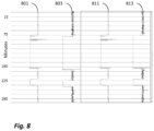
- Fig. 8 illustrates an example of time-series data before and after time correction of the data, with a surface clock as the reference.
- Time series 801 is transducer data representing Surface measured Revolutions per Minute (RPM) associated with a surface reference clock.
- Time series 803 is transducer data obtained from a sensor in the wellbore, associated with the drill string, also measuring RPM. An addition of a drill pipe occurs around 75 minutes showing an illustrated example of a step function. After applying cross-correlation as described, a time shift is obtained to be applied to adjust the time of the wellbore sensor RPM data to the surface time series associated reference time.
- Time series 811 is the same transducer RPM time series data 801 associated with a surface reference clock and time series 813 is the wellbore sensor RPM data after the time adjustment determined from cross-correlation has been applied.
- Another method that may additionally be used to correct clock drift uses a dynamic cross-correlation method that is similar to the cross-correlation method.
- the key difference is the use of a smaller overlapped-time window to compute a time shift.
- a typical window size for dynamic cross-correlation is 30 minutes with a 50 percent overlapped window; however, the overlap will be dependent on the situation and the amount of clock drift.
- FIG. 9 illustrates an example before and after clock-drift correction of downhole data to a surface reference clock by the dynamic time warping method.
- Time series 901 is transducer data representing a Surface measured RPM associated with a surface reference clock.
- Time series 903 is transducer data obtained from a sensor in the wellbore, associated with the drill string, also measuring RPM.
- a time shift series of adjustments is obtained to be applied to adjust the time of the wellbore sensor RPM data.
- Time series 911 is the same transducer RPM time series data 901 associated with a surface reference clock and time series 913 is the wellbore sensor RPM data after the time adjustment determined from cross-correlation has been applied.
- the linear moveout correction accounts for travel time in which the signal travels from one sensor location in depth to the next sensor and/or to the surface.
- the ⁇ T correction is dynamic and changes as the depth of the sensor increases.
- Fig. 10 illustrates an example before and after linear moveout correction of data acquired from downhole transducers, in this case accelerometers.
- Time series 1001, 1003 and 1005 are downhole acceleration time series data acquired from sensors in the wellbore, for example in or on the drill string.
- time series data 1011, 1013 and 1015 are illustrated such that the data are substantially closer to synchronous in time relative to, for example, a surface associated reference time.
- Other time adjustments may be added after this linear moveout correction, such as the cross-correlation or time warp methods.
- Fig. 11 illustrates a method according to embodiments of the present disclosure for automatically adjusting time series data relative to a reference time.
- a first time series is acquired from a downhole sensor 1101.
- a reference time series is acquired, which may be acquired using a surface transducer related time series with a known relationship to a reference time 1103.
- a linear moveout time series is determined to adjust the first time series due to the downhole sensors being variable in depth.
- the linear moveout time offset adjustment is equal to the depth of the downhole sensor divided by signal propagation velocity 1105.
- the linear moveout offset correction may be applied to the first time series 1107.
- the first time series and the reference time series may be cross-correlated to determine a cross-correlation time offset correction to apply to the first time series 1109, and the cross-correlation time offset correction is applied 1111 to obtain a cross-correlation corrected time series.
- Fig. 12 illustrates a method according to alternative embodiments of the present disclosure for automatically adjusting time series data relative to a reference time.
- a first time series is acquired from a downhole sensor 1201.
- a reference time series is acquired, which may be acquired using a surface transducer related time series with a known relationship to a reference time 1203.
- a linear moveout time series offset adjustment is determined to adjust the first time series due to the downhole sensors being variable in depth.
- the linear moveout time offset adjustment is equal to the depth of the downhole sensor divided by signal propagation velocity or drill string 1205.
- the linear moveout time offset adjustment is applied to the first time series to obtain a moveout corrected time series 1207.
- the first time series and the reference time series are cross-correlated to determine a cross-correlation time correction to apply to the first time series 1209.
- the cross-correlation time correction is applied to the first time series 1211, to obtain a cross correlation corrected time series.
- a dynamic cross-correlation may be applied to the first time series with the reference time series to obtain dynamic cross-correlation time offset adjustments to apply to the first time series 1213.
- the dynamic time warping process may be used to determine adjustments to the data for clock drift.
- the dynamic cross-correlation time offset adjustments are applied to the cross-correlation corrected time series to obtain dynamically adjusted time series 1215. In the case dynamic time warp adjustments were determined, they can be applied to the first time series.
- Fig. 13 illustrates a method according to further embodiments of the present disclosure for automatically adjusting time series data relative to a reference time.
- a first time series is acquired from a sensor in a wellbore 1301.
- a reference time series is acquired, which may be acquired using a surface transducer related time series with a known relationship to a reference time 1303.
- a linear moveout time series offset adjustment is determined to adjust the first time series due to the downhole sensors being variable in depth.
- the linear moveout time offset adjustment is equal to the depth of the downhole sensor divided by signal propagation velocity or drill string 1305.
- the linear moveout time offset adjustment is applied to the first time series to obtain a moveout corrected time series 1307.
- a dynamic time warping may be applied to the first time series with respect to the reference time series to determine a series of dynamic time warp offset adjustments to apply to the first time series 1309.
- the series of dynamic time warp offset adjustments are then applied to the first time series to obtain a dynamically adjusted time series 1311.
- Fig. 14 illustrates a schematic diagram of an embodiment of a system 1400 that may correspond to or may be part of a computer and/or any other computing device, such as a workstation, server, mainframe, super computer, processing graph and/or database.
- the system 1400 includes a processor 1402, which may be also be referenced as a central processor unit (CPU).
- the processor 1402 may communicate and/or provide instructions to other components within the system 1400, such as the input interface 1404, output interface 1406, and/or memory 1408.
- the processor 1402 may include one or more multi-core processors and/or memory (e.g., cache memory) that function as buffers and/or storage for data.
- processor 1402 may be part of one or more other processing components, such as application specific integrated circuits (ASICs), field-programmable gate arrays (FPGAs), and/or digital signal processors (DSPs).
- ASICs application specific integrated circuits
- FPGAs field-programmable gate arrays
- DSPs digital signal processors
- Fig. 14 illustrates that processor 1402 may be a single processor, it will be understood that processor 802 is not so limited and instead may represent a plurality of processors including massively parallel implementations and processing graphs comprising mathematical operators connected by data streams distributed across multiple platforms, including cloud-based resources.
- the processor 1402 may be configured to implement any of the methods described herein.
- Memory 1408 may be operatively coupled to processor 1402.
- Memory 1408 may be a non-transitory medium configured to store various types of data.
- memory 1408 may include one or more memory devices that comprise secondary storage, read-only memory (ROM), and/or random-access memory (RAM).
- the secondary storage is typically comprised of one or more disk drives, optical drives, solid-state drives (SSDs), and/or tape drives and is used for non-volatile storage of data.
- the secondary storage may be used to store overflow data if the allocated RAM is not large enough to hold all working data.
- the secondary storage may also be used to store programs that are loaded into the RAM when such programs are selected for execution.
- the ROM is used to store instructions and perhaps data that are read during program execution.
- the ROM is a non-volatile memory device that typically has a small memory capacity relative to the larger memory capacity of the secondary storage.
- the RAM is used to store volatile data and perhaps to store instructions.
- the memory 1408 may be used to house the instructions for carrying out various embodiments described herein.
- the memory 1408 may comprise a computer program module 1410, which may embody a computer program product, which may be accessed and implemented by processor 1402.
- application interface 1412 may be stored and accessed within memory by processor 1402.
- the program module or application interface may perform signal processing and/or conditioning and applying analytics to the time series data as described herein.
- Programming and/or loading executable instructions onto memory 1408 and processor 1402 in order to transform the system 1400 into a particular machine or apparatus that operates on time series data is well known in the art.
- Implementing instructions, real-time monitoring, and other functions by loading executable software into a computer can be converted to a hardware implementation by well-known design rules. For example, decisions between implementing a concept in software versus hardware may depend on a number of design choices that include stability of the design and numbers of units to be produced and issues involved in translating from the software domain to the hardware domain.
- Often a design may be developed and tested in a software form and subsequently transformed, by well-known design rules, to an equivalent hardware implementation in an ASIC or application specific hardware that hardwires the instructions of the software.
- a machine controlled by a new ASIC is a particular machine or apparatus, likewise a computer that has been programmed and/or loaded with executable instructions may be viewed as a particular machine or apparatus.
- Fig. 14 illustrates that the processor 1402 may be operatively coupled to an input interface 1404 configured to obtain the time series data and output interface 1406 configured to output and/or display the results or pass the results to other processing.
- the input interface 1404 may be configured to obtain the time series data via sensors, cables, connectors, and/or communication protocols.
- the input interface 1404 may be a network interface that comprises a plurality of ports configured to receive and/or transmit time series data via a network.
- the network may transmit the acquired time series data via wired links, wireless link, and/or logical links.
- Other examples of the input interface 1404 may be universal serial bus (USB) interfaces, CD-ROMs, DVD-ROMs.
- the output interface 1406 may include, but is not limited to one or more connections for a graphic display (e.g., monitors) and/or a printing device that produces hard-copies of the generated results.
- nonlimiting embodiments according to the present disclosure provide a system for determining a rig-state of a drilling rig during a wellbore drilling operation 1501, which comprises a computer (1400) comprising a memory (1408) and a processor (1402) 1503, a plurality of sensors (103, 110) associated with a wellbore drilling operation 102, 104 for acquiring time series data wherein the data are formatted for sample and bandwidth regularization and time-corrected to provide substantially time-synchronized data 1505, a processing graph of data-stream networked mathematical operators ( Fig. 2 ) that applies continuous analytics to the data at least as rapidly as the data are acquired to determine dynamic conditions of a plurality of rig conditions associated with the wellbore drilling operation 1507 and determining a rig-state from the plurality of rig conditions 1509.
- the processing graph may comprise an output data stream of the processing graph that detects and quantifies a drilling dysfunction 1511.
- the processing graph further may output data streams of rig control instructions for the purpose of mitigating a drilling dysfunction 1513.
- the rig control instructions may be altering RPM, altering weight-on-bit, altering pump pressure, or altering top-drive rotational parameters 1515.
- the processing may also output a characterization of tortuosity of a wellbore 1517.
- the acquired time series data input to the processing graph may be rotary drilling measurements, sliding measurements, reaming measurements, back reaming measurements, or tripping related measurements 1519.
- Processing graph output may be an energy loss correction of surface-derived measurements or a weight-on-bit correction 1521.
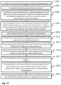
- a process for determining a rig-state of a drill rig during a wellbore drilling operation 1601 comprises acquiring data from a plurality of sensors associated with a wellbore 1603, formatting the acquired data for sample and bandwidth regularization 1605, time-correcting the data to provide substantially isochronously sampled data from the plurality of sensors 1607, processing the acquired data through a processing graph of networked mathematical operators that apply continuous analytics to the data at least as rapidly as the data are acquired to determine dynamic conditions of a plurality of rig operations associated with the wellbore 1609 and determining a rig-state from the plurality of rig operations conditions 1611.
- determining a rig-state further comprises detection and quantification of a drilling dysfunction 1613.
- the processing graph may output data streams of rig control instructions to alter rig operations to mitigate a drilling dysfunction 1615.
- the rig control instructions may be altering RPM, altering WOB, altering pump pressure or altering top-drive rotational parameters 1617.
- the output of the processing graph may be a characterization of tortuosity of a wellbore 1619.
- the acquired data input to the processing graph may be rotary drilling measurements, drill-string sliding measurements, reaming measurements, back reaming measurements, or tripping related measurements 1621.
- Other output data streams from the processing graph may be an energy loss correction of surface-derived input data streams or a weight-on-bit correction 1623.
- a drilling rig apparatus for mitigating drilling dysfunctions comprises a drill rig associated with a plurality of sensors providing time series data to a surface-based aggregator wherein the data are formatted for sample and bandwidth regularization and time-corrected to provide substantially time-synchronized data, a computer comprising a memory and a processor, a processing graph of data-stream networked mathematical operators that applies continuous analytics at least as rapidly as the time-series are acquired to determine dynamic conditions of a plurality of rig conditions associated with wellbore drilling operation and detecting a drilling dysfunction from the plurality of rig conditions.
- the processing graph outputs data streams of rig control instructions for the purpose of mitigating the detected drilling dysfunction.
- the rig control instructions may be for altering RPM, altering weight on bit, altering pump pressure or altering top-drive rotational parameters.
- An output data stream of the processing graph may quantify a drilling dysfunction.
- a computer program product is embodied in non-transitory computer readable media, the computer program product adapted to execute a process to mitigate a drilling dysfunction during a wellbore drilling operation, which comprises acquiring data from a plurality of sensors associated with a wellbore drilling operation, formatting the acquired data for sample and bandwidth regularization, time-correcting the data to provide substantially synchronously sampled data from the plurality of sensors, processing the acquired data through a processing graph of networked mathematical operators that apply continuous analytics to the data at least as rapidly as the data are acquired to determine dynamic conditions of a plurality of rig operations associated with the wellbore, detecting a drilling dysfunction from the plurality of rig operations conditions, and outputting drill rig control instructions to mitigate the detected drilling dysfunction.
Landscapes
- Engineering & Computer Science (AREA)
- Life Sciences & Earth Sciences (AREA)
- Mining & Mineral Resources (AREA)
- Geology (AREA)
- Physics & Mathematics (AREA)
- Environmental & Geological Engineering (AREA)
- Fluid Mechanics (AREA)
- General Life Sciences & Earth Sciences (AREA)
- Geochemistry & Mineralogy (AREA)
- Automation & Control Theory (AREA)
- General Physics & Mathematics (AREA)
- General Engineering & Computer Science (AREA)
- Earth Drilling (AREA)
Claims (7)
- Prozess zum Bestimmen eines Anlagenzustands einer Bohranlage (101) während eines Bohrloch-Bohrbetriebs, wobei der Prozess umfasst:a. Erfassen von von der Oberfläche abgeleiteten Eingangsdatenströmen von einer Vielzahl von Sensoren (103), die einem Bohrloch (102) zugeordnet sind;b. Formatieren der erfassten Daten zur Proben- und Bandbreitenregulierung;c. Zeitkorrigieren der Daten, um isochron als Probe genommene Daten von der Vielzahl von Sensoren bereitzustellen;d. Verarbeiten der erfassten Daten durch einen Verarbeitungsgraphen vernetzter mathematischer Operatoren, die kontinuierliche Analysen so schnell auf die Daten anwenden, wie die Daten erfasst werden, um dynamische Bedingungen einer Vielzahl von dem Bohrloch (102) zugeordneten Anlagenbetrieben zu bestimmen; unde. Bestimmen eines Anlagenzustands aus der Vielzahl von Anlagenbetriebsbedingungen;dadurch gekennzeichnet, dassSchritt b. Regulieren der Probennahme, um variable Probenraten von den Sensoren (103) zu berücksichtigen, und das Regulieren der Bandbreite beinhaltet, um variable Auflösung der Sensoren (103) zu berücksichtigen; undSchritt e. eine probenweise automatisierte Kategorisierung laufender Anlagenbetriebe umfasst, die aus den Eingangsdatenströmen berechnet wird, um Wissen über den Anlagenzustand für jede Datenprobe einzubeziehen.
- Prozess nach Anspruch 1, wobei Bestimmen eines Anlagenzustands weiter die Detektion und Quantifikation einer Bohrstörung umfasst.
- Prozess nach Anspruch 1, wobei der Verarbeitungsgraph Datenströme von Anlagensteueranweisungen ausgibt, um einen Anlagenbetrieb zum Zwecke der Abschwächung einer Bohrstörung zu ändern.
- Prozess nach Anspruch 3, wobei die Anlagensteueranweisungen mindestens eine sind aus der Gruppe, bestehend aus i) Ändern der U/min, ii) Ändern der Bohrmeißelbelastung, iii) Ändern des Pumpendrucks, und iv) Ändern der Drehparameter des Kraftdrehkopfes.
- Prozess nach Anspruch 1, wobei der Verarbeitungsgraph einen Datenstrom ausgibt, der die Tortuosität eines Bohrlochs charakterisiert.
- Prozess nach Anspruch 1, wobei die erfassten Daten, die in den Verarbeitungsgraphen eingegeben werden, mindestens eines sind, ausgewählt aus der Gruppe bestehend aus i) Drehbohrmessungen, ii) Bohrstranggleitmessungen, iii) Aufweitungsmessungen, iv) Rückaufweitungsmessungen, und v) Tripping-bezogenen Messungen.
- Prozess nach Anspruch 1, wobei der Verarbeitungsgraph einen Datenstrom ausgibt, der mindestens einer ist, ausgewählt aus der Gruppe bestehend aus: i) einer Energieverlustkorrektur von von der Oberfläche abgeleiteten Eingangsdatenströmen, und ii) einer Bohrmeißelbelastungskorrektur.
Applications Claiming Priority (2)
| Application Number | Priority Date | Filing Date | Title |
|---|---|---|---|
| US201562160998P | 2015-05-13 | 2015-05-13 | |
| PCT/US2016/032019 WO2016183286A1 (en) | 2015-05-13 | 2016-05-12 | Big drilling data analytics engine |
Publications (3)
| Publication Number | Publication Date |
|---|---|
| EP3294990A1 EP3294990A1 (de) | 2018-03-21 |
| EP3294990A4 EP3294990A4 (de) | 2018-08-08 |
| EP3294990B1 true EP3294990B1 (de) | 2025-06-25 |
Family
ID=61169617
Family Applications (1)
| Application Number | Title | Priority Date | Filing Date |
|---|---|---|---|
| EP16793504.8A Active EP3294990B1 (de) | 2015-05-13 | 2016-05-12 | Grosse engine zur bohrdatenanalyse |
Country Status (2)
| Country | Link |
|---|---|
| EP (1) | EP3294990B1 (de) |
| CN (1) | CN107709700B (de) |
Families Citing this family (12)
| Publication number | Priority date | Publication date | Assignee | Title |
|---|---|---|---|---|
| US11692432B2 (en) * | 2018-06-11 | 2023-07-04 | Schlumberger Technology Corporation | Real time surveying while drilling |
| EP3899203A1 (de) * | 2018-12-17 | 2021-10-27 | Saudi Arabian Oil Company | Bildbasierte inspektion von bohrlochausrüstungen |
| EP3789579B1 (de) * | 2019-09-05 | 2023-01-11 | Sandvik Mining and Construction Oy | Vorrichtung, verfahren und softwareprodukt zur bohrsequenzplanung |
| CN111460701B (zh) * | 2020-03-09 | 2022-09-06 | 中海油田服务股份有限公司 | 一种故障诊断模型训练方法和装置 |
| EP4121722B1 (de) * | 2020-03-17 | 2024-09-18 | Eaton Intelligent Power Limited | Sensordatenintegration und ereigniserkennung |
| CN111364969A (zh) * | 2020-03-28 | 2020-07-03 | 西安石油大学 | 一种用于生成井筒钻井参数的可视化表示的方法 |
| CN112459706B (zh) * | 2020-11-11 | 2022-09-02 | 中石化石油工程技术服务有限公司 | 一种利用空气锤三轴振动信号识别井下憋跳钻的方法 |
| CN113011507B (zh) * | 2021-03-24 | 2022-05-06 | 支付宝(杭州)信息技术有限公司 | 建立同步时间预测模型的方法、数据同步方法及对应装置 |
| CN113187464B (zh) * | 2021-04-16 | 2025-06-10 | 中国石油化工集团有限公司 | 一种具有井下故障预警功能的钻井监控系统 |
| CN114183068B (zh) * | 2022-02-16 | 2022-04-15 | 山东省煤田地质局第五勘探队 | 一种矿山井下物探用数据快速采集装置 |
| CN117094176B (zh) * | 2023-10-16 | 2023-12-15 | 中国矿业大学(北京) | 利用层理结构和微观力学性质评价页岩成缝能力的方法 |
| CN119181256B (zh) * | 2024-11-25 | 2025-06-27 | 南京信息工程大学 | 基于气象信息融合的深度学习交通流量预测方法 |
Citations (3)
| Publication number | Priority date | Publication date | Assignee | Title |
|---|---|---|---|---|
| WO2004059124A1 (en) * | 2002-12-31 | 2004-07-15 | Schlumberger Technology B.V. | Method and system for averting or mitigating undesirable drilling events |
| US20070284147A1 (en) * | 2005-02-01 | 2007-12-13 | Smith International, Inc. | System for optimizing drilling in real time |
| EP2222937B1 (de) * | 2007-10-30 | 2014-12-31 | BP Corporation North America Inc. | Intelligenter bohr-advisor |
Family Cites Families (19)
| Publication number | Priority date | Publication date | Assignee | Title |
|---|---|---|---|---|
| GB2104752B (en) * | 1981-07-20 | 1986-02-19 | Chevron Res | Optical communication system for drill hole logging |
| FR2613496B1 (fr) * | 1987-04-02 | 1989-07-21 | Inst Francais Du Petrole | Dispositif pour l'acquisition de donnees sismiques dans un forage et leur transmission a un systeme central de commande et d'enregistrement |
| US5283768A (en) * | 1991-06-14 | 1994-02-01 | Baker Hughes Incorporated | Borehole liquid acoustic wave transducer |
| US6021377A (en) * | 1995-10-23 | 2000-02-01 | Baker Hughes Incorporated | Drilling system utilizing downhole dysfunctions for determining corrective actions and simulating drilling conditions |
| CA2357921C (en) * | 2000-09-29 | 2007-02-06 | Baker Hughes Incorporated | Method and apparatus for prediction control in drilling dynamics using neural networks |
| EA007498B1 (ru) * | 2002-04-19 | 2006-10-27 | Марк У. Хатчинсон | Способ и устройство для определения моды движения бурильной колонны |
| CN1284920C (zh) * | 2004-09-16 | 2006-11-15 | 辽宁工程技术大学 | 油田智能钻井监控系统 |
| US20090076873A1 (en) * | 2007-09-19 | 2009-03-19 | General Electric Company | Method and system to improve engineered system decisions and transfer risk |
| US9664012B2 (en) * | 2008-08-20 | 2017-05-30 | Foro Energy, Inc. | High power laser decomissioning of multistring and damaged wells |
| CN101446191B (zh) * | 2008-11-17 | 2013-08-21 | 文必用 | 一种钻井井控参数智能监测系统 |
| US8170800B2 (en) * | 2009-03-16 | 2012-05-01 | Verdande Technology As | Method and system for monitoring a drilling operation |
| US8443900B2 (en) * | 2009-05-18 | 2013-05-21 | Zeitecs B.V. | Electric submersible pumping system and method for dewatering gas wells |
| US20120118637A1 (en) * | 2009-08-07 | 2012-05-17 | Jingbo Wang | Drilling Advisory Systems And Methods Utilizing Objective Functions |
| CN102168547A (zh) * | 2011-03-15 | 2011-08-31 | 中国石油大学(华东) | 一种基于小波神经网络的深水防喷器组故障诊断系统 |
| US8752648B2 (en) * | 2011-11-02 | 2014-06-17 | Landmark Graphics Corporation | Method and system for predicting a drill string stuck pipe event |
| US9262713B2 (en) * | 2012-09-05 | 2016-02-16 | Carbo Ceramics Inc. | Wellbore completion and hydraulic fracturing optimization methods and associated systems |
| US9022140B2 (en) * | 2012-10-31 | 2015-05-05 | Resource Energy Solutions Inc. | Methods and systems for improved drilling operations using real-time and historical drilling data |
| CN103323228A (zh) * | 2013-07-02 | 2013-09-25 | 中煤科工集团西安研究院 | 一种矿用钻机故障智能识别方法 |
| CN104405375A (zh) * | 2014-10-17 | 2015-03-11 | 华中科技大学 | 一种基于磁反馈的井间电磁测井信号接收电子系统 |
-
2016
- 2016-05-12 EP EP16793504.8A patent/EP3294990B1/de active Active
- 2016-05-12 CN CN201680039309.9A patent/CN107709700B/zh active Active
Patent Citations (3)
| Publication number | Priority date | Publication date | Assignee | Title |
|---|---|---|---|---|
| WO2004059124A1 (en) * | 2002-12-31 | 2004-07-15 | Schlumberger Technology B.V. | Method and system for averting or mitigating undesirable drilling events |
| US20070284147A1 (en) * | 2005-02-01 | 2007-12-13 | Smith International, Inc. | System for optimizing drilling in real time |
| EP2222937B1 (de) * | 2007-10-30 | 2014-12-31 | BP Corporation North America Inc. | Intelligenter bohr-advisor |
Also Published As
| Publication number | Publication date |
|---|---|
| CN107709700B (zh) | 2024-12-31 |
| EP3294990A1 (de) | 2018-03-21 |
| CN107709700A (zh) | 2018-02-16 |
| EP3294990A4 (de) | 2018-08-08 |
Similar Documents
| Publication | Publication Date | Title |
|---|---|---|
| US10788801B2 (en) | Big drilling data analytics engine | |
| EP3294990B1 (de) | Grosse engine zur bohrdatenanalyse | |
| US10120343B2 (en) | Time corrections for drilling data | |
| US10302785B2 (en) | Geosteering using rock geomechanical properties derived from drilling data and an accurate drilling model | |
| US8024124B2 (en) | Determining maximum horizontal stress in an earth formation | |
| RU2582608C1 (ru) | Вычисление скорости и глубины бурения для скважинных инструментов | |
| US8362915B2 (en) | System and method for determining stretch or compression of a drill string | |
| RU2663653C1 (ru) | Улучшенная оценка искривления ствола скважины, основанная на результатах измерений изгибающего момента инструмента | |
| US12006813B2 (en) | Real-time curvature estimation for autonomous directional drilling | |
| CN1656302B (zh) | 定量测定事件后地质构造特性变化的系统和方法 | |
| EP3294987B1 (de) | Zeitkorrekturen für bohrdaten | |
| US20220187494A1 (en) | Decomposed friction factor calibration | |
| US11230913B2 (en) | Power loss dysfunction characterization | |
| EP3294989B1 (de) | Charakterisierung von leistungsverlustdysfunktion |
Legal Events
| Date | Code | Title | Description |
|---|---|---|---|
| STAA | Information on the status of an ep patent application or granted ep patent |
Free format text: STATUS: THE INTERNATIONAL PUBLICATION HAS BEEN MADE |
|
| PUAI | Public reference made under article 153(3) epc to a published international application that has entered the european phase |
Free format text: ORIGINAL CODE: 0009012 |
|
| STAA | Information on the status of an ep patent application or granted ep patent |
Free format text: STATUS: REQUEST FOR EXAMINATION WAS MADE |
|
| 17P | Request for examination filed |
Effective date: 20171208 |
|
| AK | Designated contracting states |
Kind code of ref document: A1 Designated state(s): AL AT BE BG CH CY CZ DE DK EE ES FI FR GB GR HR HU IE IS IT LI LT LU LV MC MK MT NL NO PL PT RO RS SE SI SK SM TR |
|
| AX | Request for extension of the european patent |
Extension state: BA ME |
|
| A4 | Supplementary search report drawn up and despatched |
Effective date: 20180711 |
|
| RIC1 | Information provided on ipc code assigned before grant |
Ipc: G01V 1/28 20060101ALI20180705BHEP Ipc: E21B 49/00 20060101ALI20180705BHEP Ipc: G01V 1/50 20060101ALI20180705BHEP Ipc: E21B 47/12 20120101AFI20180705BHEP Ipc: E21B 47/18 20120101ALI20180705BHEP Ipc: E21B 44/04 20060101ALI20180705BHEP Ipc: G01V 1/46 20060101ALI20180705BHEP |
|
| DAV | Request for validation of the european patent (deleted) | ||
| DAX | Request for extension of the european patent (deleted) | ||
| STAA | Information on the status of an ep patent application or granted ep patent |
Free format text: STATUS: EXAMINATION IS IN PROGRESS |
|
| 17Q | First examination report despatched |
Effective date: 20180918 |
|
| RAP1 | Party data changed (applicant data changed or rights of an application transferred) |
Owner name: CONOCOPHILLIPS COMPANY |
|
| RAP1 | Party data changed (applicant data changed or rights of an application transferred) |
Owner name: CONOCOPHILLIPS COMPANY |
|
| P01 | Opt-out of the competence of the unified patent court (upc) registered |
Effective date: 20231207 |
|
| GRAP | Despatch of communication of intention to grant a patent |
Free format text: ORIGINAL CODE: EPIDOSNIGR1 |
|
| STAA | Information on the status of an ep patent application or granted ep patent |
Free format text: STATUS: GRANT OF PATENT IS INTENDED |
|
| INTG | Intention to grant announced |
Effective date: 20250325 |
|
| GRAS | Grant fee paid |
Free format text: ORIGINAL CODE: EPIDOSNIGR3 |
|
| GRAA | (expected) grant |
Free format text: ORIGINAL CODE: 0009210 |
|
| STAA | Information on the status of an ep patent application or granted ep patent |
Free format text: STATUS: THE PATENT HAS BEEN GRANTED |
|
| AK | Designated contracting states |
Kind code of ref document: B1 Designated state(s): AL AT BE BG CH CY CZ DE DK EE ES FI FR GB GR HR HU IE IS IT LI LT LU LV MC MK MT NL NO PL PT RO RS SE SI SK SM TR |
|
| REG | Reference to a national code |
Ref country code: GB Ref legal event code: FG4D |
|
| REG | Reference to a national code |
Ref country code: CH Ref legal event code: EP |
|
| REG | Reference to a national code |
Ref country code: DE Ref legal event code: R096 Ref document number: 602016092670 Country of ref document: DE |
|
| REG | Reference to a national code |
Ref country code: CH Ref legal event code: EP |
|
| REG | Reference to a national code |
Ref country code: IE Ref legal event code: FG4D |
|
| PG25 | Lapsed in a contracting state [announced via postgrant information from national office to epo] |
Ref country code: FI Free format text: LAPSE BECAUSE OF FAILURE TO SUBMIT A TRANSLATION OF THE DESCRIPTION OR TO PAY THE FEE WITHIN THE PRESCRIBED TIME-LIMIT Effective date: 20250625 |
|
| REG | Reference to a national code |
Ref country code: LT Ref legal event code: MG9D |
|
| PG25 | Lapsed in a contracting state [announced via postgrant information from national office to epo] |
Ref country code: GR Free format text: LAPSE BECAUSE OF FAILURE TO SUBMIT A TRANSLATION OF THE DESCRIPTION OR TO PAY THE FEE WITHIN THE PRESCRIBED TIME-LIMIT Effective date: 20250926 |
|
| PG25 | Lapsed in a contracting state [announced via postgrant information from national office to epo] |
Ref country code: BG Free format text: LAPSE BECAUSE OF FAILURE TO SUBMIT A TRANSLATION OF THE DESCRIPTION OR TO PAY THE FEE WITHIN THE PRESCRIBED TIME-LIMIT Effective date: 20250625 |
|
| PG25 | Lapsed in a contracting state [announced via postgrant information from national office to epo] |
Ref country code: HR Free format text: LAPSE BECAUSE OF FAILURE TO SUBMIT A TRANSLATION OF THE DESCRIPTION OR TO PAY THE FEE WITHIN THE PRESCRIBED TIME-LIMIT Effective date: 20250625 |
|
| PG25 | Lapsed in a contracting state [announced via postgrant information from national office to epo] |
Ref country code: RS Free format text: LAPSE BECAUSE OF FAILURE TO SUBMIT A TRANSLATION OF THE DESCRIPTION OR TO PAY THE FEE WITHIN THE PRESCRIBED TIME-LIMIT Effective date: 20250925 |
|
| PG25 | Lapsed in a contracting state [announced via postgrant information from national office to epo] |
Ref country code: LV Free format text: LAPSE BECAUSE OF FAILURE TO SUBMIT A TRANSLATION OF THE DESCRIPTION OR TO PAY THE FEE WITHIN THE PRESCRIBED TIME-LIMIT Effective date: 20250625 |
|
| REG | Reference to a national code |
Ref country code: NL Ref legal event code: MP Effective date: 20250625 |
|
| PG25 | Lapsed in a contracting state [announced via postgrant information from national office to epo] |
Ref country code: NL Free format text: LAPSE BECAUSE OF FAILURE TO SUBMIT A TRANSLATION OF THE DESCRIPTION OR TO PAY THE FEE WITHIN THE PRESCRIBED TIME-LIMIT Effective date: 20250625 |
|
| PG25 | Lapsed in a contracting state [announced via postgrant information from national office to epo] |
Ref country code: PT Free format text: LAPSE BECAUSE OF FAILURE TO SUBMIT A TRANSLATION OF THE DESCRIPTION OR TO PAY THE FEE WITHIN THE PRESCRIBED TIME-LIMIT Effective date: 20251027 |
|
| REG | Reference to a national code |
Ref country code: AT Ref legal event code: MK05 Ref document number: 1806620 Country of ref document: AT Kind code of ref document: T Effective date: 20250625 |
|
| PG25 | Lapsed in a contracting state [announced via postgrant information from national office to epo] |
Ref country code: IS Free format text: LAPSE BECAUSE OF FAILURE TO SUBMIT A TRANSLATION OF THE DESCRIPTION OR TO PAY THE FEE WITHIN THE PRESCRIBED TIME-LIMIT Effective date: 20251025 |
|
| PG25 | Lapsed in a contracting state [announced via postgrant information from national office to epo] |
Ref country code: AT Free format text: LAPSE BECAUSE OF FAILURE TO SUBMIT A TRANSLATION OF THE DESCRIPTION OR TO PAY THE FEE WITHIN THE PRESCRIBED TIME-LIMIT Effective date: 20250625 Ref country code: SM Free format text: LAPSE BECAUSE OF FAILURE TO SUBMIT A TRANSLATION OF THE DESCRIPTION OR TO PAY THE FEE WITHIN THE PRESCRIBED TIME-LIMIT Effective date: 20250625 |
|
| PG25 | Lapsed in a contracting state [announced via postgrant information from national office to epo] |
Ref country code: CZ Free format text: LAPSE BECAUSE OF FAILURE TO SUBMIT A TRANSLATION OF THE DESCRIPTION OR TO PAY THE FEE WITHIN THE PRESCRIBED TIME-LIMIT Effective date: 20250625 |
|
| PG25 | Lapsed in a contracting state [announced via postgrant information from national office to epo] |
Ref country code: PL Free format text: LAPSE BECAUSE OF FAILURE TO SUBMIT A TRANSLATION OF THE DESCRIPTION OR TO PAY THE FEE WITHIN THE PRESCRIBED TIME-LIMIT Effective date: 20250625 |
|
| PG25 | Lapsed in a contracting state [announced via postgrant information from national office to epo] |
Ref country code: EE Free format text: LAPSE BECAUSE OF FAILURE TO SUBMIT A TRANSLATION OF THE DESCRIPTION OR TO PAY THE FEE WITHIN THE PRESCRIBED TIME-LIMIT Effective date: 20250625 |
|
| PG25 | Lapsed in a contracting state [announced via postgrant information from national office to epo] |
Ref country code: SK Free format text: LAPSE BECAUSE OF FAILURE TO SUBMIT A TRANSLATION OF THE DESCRIPTION OR TO PAY THE FEE WITHIN THE PRESCRIBED TIME-LIMIT Effective date: 20250625 Ref country code: RO Free format text: LAPSE BECAUSE OF FAILURE TO SUBMIT A TRANSLATION OF THE DESCRIPTION OR TO PAY THE FEE WITHIN THE PRESCRIBED TIME-LIMIT Effective date: 20250625 |
|
| PG25 | Lapsed in a contracting state [announced via postgrant information from national office to epo] |
Ref country code: ES Free format text: LAPSE BECAUSE OF FAILURE TO SUBMIT A TRANSLATION OF THE DESCRIPTION OR TO PAY THE FEE WITHIN THE PRESCRIBED TIME-LIMIT Effective date: 20250625 |