EP3294525B1 - Poste de moulage pour les machines de moulage par soufflage sans coussins de pression - Google Patents
Poste de moulage pour les machines de moulage par soufflage sans coussins de pression Download PDFInfo
- Publication number
- EP3294525B1 EP3294525B1 EP17700013.0A EP17700013A EP3294525B1 EP 3294525 B1 EP3294525 B1 EP 3294525B1 EP 17700013 A EP17700013 A EP 17700013A EP 3294525 B1 EP3294525 B1 EP 3294525B1
- Authority
- EP
- European Patent Office
- Prior art keywords
- locking element
- locking
- side part
- transforming station
- respect
- Prior art date
- Legal status (The legal status is an assumption and is not a legal conclusion. Google has not performed a legal analysis and makes no representation as to the accuracy of the status listed.)
- Active
Links
- 238000000071 blow moulding Methods 0.000 title description 6
- 230000007246 mechanism Effects 0.000 claims description 13
- 238000000034 method Methods 0.000 claims description 12
- 230000001131 transforming effect Effects 0.000 claims 19
- 239000011796 hollow space material Substances 0.000 claims 2
- 239000000969 carrier Substances 0.000 description 31
- 238000013016 damping Methods 0.000 description 7
- 238000007493 shaping process Methods 0.000 description 6
- 239000000725 suspension Substances 0.000 description 4
- 230000009969 flowable effect Effects 0.000 description 3
- 238000004519 manufacturing process Methods 0.000 description 3
- 229910000831 Steel Inorganic materials 0.000 description 2
- 238000007664 blowing Methods 0.000 description 2
- 230000003068 static effect Effects 0.000 description 2
- 239000010959 steel Substances 0.000 description 2
- 238000013459 approach Methods 0.000 description 1
- 230000001419 dependent effect Effects 0.000 description 1
- 238000011161 development Methods 0.000 description 1
- 230000018109 developmental process Effects 0.000 description 1
- 230000000694 effects Effects 0.000 description 1
- 239000013013 elastic material Substances 0.000 description 1
- 238000010438 heat treatment Methods 0.000 description 1
- 239000000314 lubricant Substances 0.000 description 1
- 230000007257 malfunction Effects 0.000 description 1
- 239000000463 material Substances 0.000 description 1
- 238000011089 mechanical engineering Methods 0.000 description 1
- 230000003746 surface roughness Effects 0.000 description 1
Images


Classifications
-
- B—PERFORMING OPERATIONS; TRANSPORTING
- B29—WORKING OF PLASTICS; WORKING OF SUBSTANCES IN A PLASTIC STATE IN GENERAL
- B29C—SHAPING OR JOINING OF PLASTICS; SHAPING OF MATERIAL IN A PLASTIC STATE, NOT OTHERWISE PROVIDED FOR; AFTER-TREATMENT OF THE SHAPED PRODUCTS, e.g. REPAIRING
- B29C49/00—Blow-moulding, i.e. blowing a preform or parison to a desired shape within a mould; Apparatus therefor
- B29C49/42—Component parts, details or accessories; Auxiliary operations
- B29C49/56—Opening, closing or clamping means
-
- B—PERFORMING OPERATIONS; TRANSPORTING
- B29—WORKING OF PLASTICS; WORKING OF SUBSTANCES IN A PLASTIC STATE IN GENERAL
- B29C—SHAPING OR JOINING OF PLASTICS; SHAPING OF MATERIAL IN A PLASTIC STATE, NOT OTHERWISE PROVIDED FOR; AFTER-TREATMENT OF THE SHAPED PRODUCTS, e.g. REPAIRING
- B29C49/00—Blow-moulding, i.e. blowing a preform or parison to a desired shape within a mould; Apparatus therefor
- B29C49/42—Component parts, details or accessories; Auxiliary operations
- B29C49/4205—Handling means, e.g. transfer, loading or discharging means
-
- B—PERFORMING OPERATIONS; TRANSPORTING
- B29—WORKING OF PLASTICS; WORKING OF SUBSTANCES IN A PLASTIC STATE IN GENERAL
- B29C—SHAPING OR JOINING OF PLASTICS; SHAPING OF MATERIAL IN A PLASTIC STATE, NOT OTHERWISE PROVIDED FOR; AFTER-TREATMENT OF THE SHAPED PRODUCTS, e.g. REPAIRING
- B29C49/00—Blow-moulding, i.e. blowing a preform or parison to a desired shape within a mould; Apparatus therefor
- B29C49/42—Component parts, details or accessories; Auxiliary operations
- B29C49/48—Moulds
- B29C2049/4879—Moulds characterised by mould configurations
- B29C2049/4892—Mould halves consisting of an independent main and bottom part
-
- B—PERFORMING OPERATIONS; TRANSPORTING
- B29—WORKING OF PLASTICS; WORKING OF SUBSTANCES IN A PLASTIC STATE IN GENERAL
- B29C—SHAPING OR JOINING OF PLASTICS; SHAPING OF MATERIAL IN A PLASTIC STATE, NOT OTHERWISE PROVIDED FOR; AFTER-TREATMENT OF THE SHAPED PRODUCTS, e.g. REPAIRING
- B29C49/00—Blow-moulding, i.e. blowing a preform or parison to a desired shape within a mould; Apparatus therefor
- B29C49/42—Component parts, details or accessories; Auxiliary operations
- B29C49/56—Opening, closing or clamping means
- B29C2049/566—Locking means
-
- B—PERFORMING OPERATIONS; TRANSPORTING
- B29—WORKING OF PLASTICS; WORKING OF SUBSTANCES IN A PLASTIC STATE IN GENERAL
- B29C—SHAPING OR JOINING OF PLASTICS; SHAPING OF MATERIAL IN A PLASTIC STATE, NOT OTHERWISE PROVIDED FOR; AFTER-TREATMENT OF THE SHAPED PRODUCTS, e.g. REPAIRING
- B29C2949/00—Indexing scheme relating to blow-moulding
- B29C2949/07—Preforms or parisons characterised by their configuration
- B29C2949/0715—Preforms or parisons characterised by their configuration the preform having one end closed
-
- B—PERFORMING OPERATIONS; TRANSPORTING
- B29—WORKING OF PLASTICS; WORKING OF SUBSTANCES IN A PLASTIC STATE IN GENERAL
- B29C—SHAPING OR JOINING OF PLASTICS; SHAPING OF MATERIAL IN A PLASTIC STATE, NOT OTHERWISE PROVIDED FOR; AFTER-TREATMENT OF THE SHAPED PRODUCTS, e.g. REPAIRING
- B29C49/00—Blow-moulding, i.e. blowing a preform or parison to a desired shape within a mould; Apparatus therefor
- B29C49/02—Combined blow-moulding and manufacture of the preform or the parison
- B29C49/06—Injection blow-moulding
-
- B—PERFORMING OPERATIONS; TRANSPORTING
- B29—WORKING OF PLASTICS; WORKING OF SUBSTANCES IN A PLASTIC STATE IN GENERAL
- B29L—INDEXING SCHEME ASSOCIATED WITH SUBCLASS B29C, RELATING TO PARTICULAR ARTICLES
- B29L2031/00—Other particular articles
- B29L2031/712—Containers; Packaging elements or accessories, Packages
- B29L2031/7158—Bottles
Definitions
- the present invention relates to a forming station for forming plastic preforms into plastic containers.
- Such forming stations which can be parts of blow molding machines, are used to manufacture plastic bottles.
- heated plastic preforms are introduced into blow molds and are then blown into plastic containers and in particular plastic bottles.
- these forming stations usually have blow mold carriers which carry parts of blow molds.
- the plastic preforms are placed in the blow mold, this is closed and then the plastic preform is expanded.
- Locking techniques which have locking shaft systems, magnet systems or pin systems. Usually, however, only the mold carrier halves are closed and locked, so that this does not immediately achieve a flush and form-locking locking of the molded shells or the blow molded parts.
- EP1 636 005 B1 known such a device in which (as a locking device) anti-rotation barbs are shifted with respect to each other in the longitudinal direction so as to effect an engagement.
- Further locking techniques are from the documents US9050749B1 . DE102012104754A1 and US8721315B2 known.
- the present invention is therefore based on the object of reducing both the manufacturing and the process costs.
- the effort required to provide said pressure pad should be reduced. According to the invention, these objects are achieved by the subject matter of the independent claims. Advantageous embodiments and further developments are the subject of the dependent claims.
- a reshaping station for reshaping plastic preforms into plastic containers and in particular plastic bottles has two side part carriers which are intended for carrying side parts of a blow mold. Furthermore, this shaping station preferably has a base part carrier for carrying a base part of the blow mold. These side parts and the bottom part of the blow mold together form a cavity within which the plastic preforms can be formed into the plastic containers by exposure to a flowable medium and in particular compressed air.
- the two side part carriers for opening and / or closing the blow mold relative to the other side part carrier is pivotable with respect to a predetermined main axis.
- the forming station has a locking mechanism in order to lock a side part carrier with the other side part carrier (and / or one blow molding part with the other and / or a blow mold shell part with the other blow mold shell part) in a closed state of the blow mold.
- the locking mechanism a second locking element which is pivotable with respect to a predetermined pivot axis and which interlocks with a first locking element for locking the side part carriers.
- At least one of the two locking elements has a first contact surface which is suitable and intended to interact with a second contact surface of the first locking element when locking with the first locking element, at least one of these contact surfaces being designed such that when the second locking element is pivoted with respect to the pivot axis in the direction of the first locking element, the two side part carriers are pushed towards one another.
- the locking mechanism or the locking element is designed in such a way that a locked state initially arises between the side part carriers, a certain shape gap still being possible here.
- a blow molding part for example one blow mold half, is preferably fed to the other blow mold part, in particular the other blow mold half, by a further pivoting movement of the locking element.
- the locking elements preferably not only lock the side part carriers, but also, depending on the pivoting position, also cause the two blow molded parts to be pushed towards one another. In this way, a mold gap between the two blow mold side parts can be reduced.
- the pivot axis about which the locking element is pivoted is preferably about a pivot axis which runs parallel to a longitudinal axis of the containers to be formed.
- the invention thus describes a locking system of a forming station or blow molding unit, which preferably has two interlocking closing elements or locking elements, at least one locking element being rotatably mounted. At least one of these closing elements or locking elements preferably has a contact surface and, in particular, a radius or a similar geometry in an engagement region of the second locking element, which ensures that the side part carriers are closed beforehand and, depending on the design of this surface or the similar geometry, can also be used and enables flush and / or positive locking of the mold carrier halves or side part carriers.
- the respective other locking element preferably also has a corresponding surface which is adapted to the first-mentioned surface of the first locking element.
- a double function is fulfilled, namely the side part carrier is locked and, in addition, a flush and / or positive locking of the molded shells and / or the blow molded parts is effected.
- This flush closing of the molded shells eliminates the need for a pressure pad, which was used in the prior art to flush these molded shells or blow molded parts in order to ensure the desired quality of the separating seam. This quality is guaranteed here by the flush and / or positive engagement of the other side part carrier. In this way, it can be achieved that the entire pressure pad unit is dispensed with and that there is no expense with regard to leakage of the pressure pad.
- An improved self-locking through the surface for example the radius or the similar geometry, preferably also occurs on at least one of the two locking elements.
- self-locking means the resistance caused by friction against slipping or twisting of two bodies lying against each other. As soon as the static friction is exceeded, the bodies are no longer self-locking.
- the self-locking is influenced by sizes such as the angle of inclination, the surface roughness of the contact surfaces, the material pairing, the sliding speed, but also by the lubricant and the heating.
- the resulting angle is made smaller than the arctangent of the static friction coefficient. If, in the present example, the angle between the surfaces is 2.86 °, a sliding friction number of 0.05 would result to achieve self-locking (or vice versa, if the sliding friction number was 0.05, the angle would be 2.86 ° (or A coefficient of sliding friction of 0.05 is realistic when steel meets (lubricated) steel, which is the most unfavorable condition in terms of friction, so the angle between the surfaces is preferably chosen such that the self-locking mentioned occurs.
- no planes are provided that are flat to one another, but rather a surface that is slightly curved, in particular by the radius. This also increases safety, since the curved surface works like a "barb".
- the two side part carriers are first locked with respect to one another and then pushed toward one another.
- This can be done in such a way that, when the second locking element is pivoted by a first angle, preferably one locking element engages behind the other and the two side parts are pressed towards one another when pivoting in the same direction or in the same pivoting direction.
- an intervention takes place first, which locks the forming station in a closed state, and only then does one of the side part carriers move to the other side part carrier.
- the forming station is designed free of pressure pads.
- a pressure cushion for example between the side part carrier and a molded shell or else a molded shell and the side part of the blow mold, is dispensed with. Rather, the movement, which is otherwise made possible by the pressure cushion, takes place through the described delivery process, which is carried out during locking.
- the locking movement of the side part carriers therefore preferably also causes the two side parts of the blow mold to move towards one another.
- the contact surface of a locking element has a curved and / or inclined section which interacts with the contact surface of the other locking element in order to bring the two side part carriers towards one another.
- This curved and / or inclined section can be a curved section with a specific radius and / or an inclined section.
- At least one locking element is preferably designed like a hook. Both locking elements are preferably designed like hooks. At least one locking element preferably extends along the direction of the main axis. Preferably extend both locking elements along the direction of the main axis. At least one locking element is preferably formed continuously along the main axis. However, it would also be possible for a plurality of locking elements to be arranged one behind the other along the direction of the main axis and preferably also spaced apart from one another.
- the device preferably has a damping and / or suspension device which dampens this closing movement when the blow mold is closed.
- This damping device is preferably arranged on at least one of the two side part carriers.
- the device preferably has two such damping and / or suspension elements. At least one locking element is particularly preferably arranged in the direction of the main axis between these two damping and / or suspension elements.
- These damping elements can have an elastic material and / or a spring element.
- These damping and / or suspension elements preferably counteract a closing movement of the side part carriers.
- first locking element and the second locking element are designed such that, in a predetermined pivoting position of the second locking element with respect to the first locking element, the contact surfaces of the two locking elements face each other, but a gap is formed between the two contact surfaces.
- the gap is preferably formed in a circumferential direction of the pivoting movement of the two blow mold carrier parts and / or in a circumferential direction of the pivoting movement of the at least one locking element.
- the contact surfaces preferably overlap in a circumferential direction of the pivoting movement in this position in such a way that these contact surfaces would abut one another when opened.
- the contact surfaces and / or the locking elements preferably overlap in such a way that opening of the blow mold is prevented precisely by this overlap, in particular since the contact surfaces abut upon opening.
- the execution can take place in such a way that in this first pivoting position the two locking elements lie opposite one another, but still have a predetermined distance or gap from one another.
- This gap can extend in a radial direction of the pivoting movement of the at least one blow mold carrier part. The said gap therefore allows a certain play of the carriers before the blow mold carrier parts are closed.
- said gap can be reduced by a further pivoting movement of the second locking element.
- This further pivoting movement is in particular a further pivoting movement in the direction of a completely locked state and / or a pivoting movement which follows the above pivoting movement, which leads to the overlap between the locking elements.
- the gap is thus closed by a further pivoting movement of the second locking element.
- the above-mentioned gap preferably also extends in the direction of the main axis.
- the side parts and / or the molded shells carrying the side parts have contacting surfaces that make contact with one another in a flat manner.
- the molded shells and / or the side parts can be placed flush against one another with a flat contact surface, so that the mold gap between the side parts can be kept small.
- At least one of these contacting surfaces has a projection which extends in the direction of the main axis.
- This can be, for example, a curved or nose-like projection.
- the other of these contacting surfaces has a recess which extends in the direction of the main axis and which is particularly preferably adapted to the projection mentioned.
- the projection can lie in the recess in a closed state of the blow mold. In this way, the two blow mold side parts and / or the mold shells are centered very precisely.
- At least one of the contact surfaces of the locking elements is a hardened contact surface. Both contact surfaces are advantageously hardened contact surfaces. In this way, rapid wear of these contact surfaces, which have to absorb comparatively high forces, can be avoided.
- the present invention is further directed to a device for shaping plastic preforms into plastic containers, this device having a movable and, in particular, rotatable carrier, on which a multiplicity of the shaping stations described above are arranged.
- the forming stations each advantageously have rod-like bodies which can be inserted into the plastic preforms in order to stretch them in the longitudinal direction.
- the reshaping stations each have loading devices in order to apply a flowable and in particular gaseous medium to the plastic preforms.
- These loading devices can, for example, be blowing nozzles which can be placed against an opening edge of the plastic preforms.
- the shaping station described above also has a base part carrier which can be locked with the described side part carriers to close the blow mold.
- the present invention is further directed to a method for closing a forming station for forming plastic preforms into plastic containers.
- the shaping station has two side part carriers for carrying side parts of a blow mold, and preferably also a bottom part carrier for carrying a bottom part of the Blow mold. These side parts and the bottom part of the blow mold jointly form a cavity within which the plastic preforms are formed into the plastic containers by exposure to a flowable and in particular gaseous medium.
- At least one of the two side part carriers is pivoted with respect to a predetermined main axis in order to close the blow mold relative to the other side part carrier and the shaping station furthermore has a locking mechanism in order to lock a side part carrier with the other side part carrier in a closed state of the blow mold.
- the locking mechanism has a second locking element which is pivoted with respect to a predetermined pivot axis and which interlocks with a first locking element to lock the side part carriers.
- At least one of the two locking elements has a first contact surface, which is suitable for interacting with the first locking element with a second contact surface of the first locking element, at least one of these contact surfaces being designed such that when the second locking element is pivoted with respect to the Pivot axis in the direction of the first locking element, the two side part carriers are pushed towards each other.
- blow mold carrier parts are first locked or locked by means of the locking elements, a certain gap or a certain play in the pivoting movement being made possible here.
- This gap is closed by a further infeed of the locking element, and the blow molded parts are preferably also pressed towards one another.
- the actual expansion process of the plastic preforms preferably takes place without the use of a pressure pad.
- a forming station of the type described above is preferably used for the method.
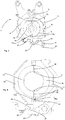
- FIG. 1 shows an illustration of a forming station 1 according to the invention.
- This forming station 1 has two side part carriers 4 and 6. These are pivotable with respect to one another and with respect to a main axis S. It is possible for both side part supports to be pivoted with respect to this main axis. It would also be possible for only one of the two side part supports to be pivoted with respect to the main axis. It would also be conceivable that two mutually parallel axes are provided, with respect to which the two side part carriers are pivoted. The main axis S or a corresponding pivot shaft here runs perpendicular to the plane of the figure.
- On the two blow mold carrier parts are each Shells 34 and 36 arranged. Blow mold side parts 14 and 16 are in turn arranged on these molded shells 34 and 36.
- reference numeral 20 denotes a locking mechanism which serves to lock the two side part carriers 4 and 6, in particular during a blowing process.
- a first locking element 22 is provided, which is fastened to the first side part carrier 4.
- a second locking element 24 is pivotally arranged on the second side part carrier.
- the reference numeral 41 denotes a lever arm by means of which the locking element 24 can be pivoted with respect to the pivot axis S1.
- the pivot axis S1 in turn is parallel to the main pivot axis S.
- a cam roller 43 can be provided with a guide curve (not shown) which is in particular stationary.
- other drives would also be conceivable, such as, in particular, electrical drives which serve to pivot the side part carriers.
- Figure 2 shows the forming station 1 in a state in which the side part carriers or the blow molding parts 14 and 16 are almost closed, but there is still no complete locking. It can be seen that the two locking elements 22 and 24 already engage in one another, but are not yet completely closed to one another. Opening the blow mold is no longer possible here.
- Figure 3 shows a representation of the forming station 1 in a not yet closed state.
- the two locking elements 22 and 24 do not yet interlock and the blow mold side parts 14 and 16 are still a clear gap open.
- the reference numerals 14a and 14b relate to contact surfaces of the first blow molded part and the reference symbols 16a and 16b relate to touch surfaces of the second blow molded part.
- the contact surfaces 14a and 16a and 14b and 16b lie against one another. The accuracy of this concern also determines the resulting form gap.
- the design of the locking elements therefore causes these two contact surfaces to be pressed against one another particularly precisely.
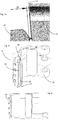
- Figure 4 again shows an enlarged view similar Figure 2 , Here the two locking elements 22 and 24 already interlock, but there is still no completely closed state. It can also be seen that the mold carrier shells 34 and 36 each form contact surfaces 42 and 44 with one another.
- the contact surface 42 has a projection 34a.
- the contact surface 44 has a recess 36a. These can interlock. This projection 34a and the recess 36a thus form a relatively large common contact surface with one another.
- first locking element has a contact surface 28 and the second locking element 24 has a second contact surface 26.
- Figure 5 shows a further representation in an almost closed state.
- the contact surfaces 26 and 28 can be seen, which cause the blow mold to be locked and the side part carriers to be moved towards one another.
- Figure 6 shows a detailed view of the locking elements 122 and 124 according to the prior art. It can be seen that these are already touching each other in the position shown. In this way, there is no longer any gap here, which allows a certain play between the blow molded parts. Also, in the event of continued pivoting, no further advancement of the blow mold parts towards one another is achieved.
- FIG 7 shows a representation of two locking elements according to the invention. It can be seen here that the contact surfaces 26 and 28 each have essentially straight sections 26a and 28a. At the in Figure 4 shown state, a gap Sp is formed between the two contact surfaces 26 and 28. This can have a width, for example, between 0.1 mm and 0.5 mm, preferably between 0.15 mm and 0.35 mm and particularly preferably between 0.2 mm and 0.3 mm. While this gap is being built up, there is still a certain amount of play between the two locking elements with respect to one another and thus also with respect to the two side part carriers on which these locking elements are arranged. With a further movement, this gap becomes complete closed and the two locking elements are also pushed towards each other. In this way, the mold gap between the blow molded parts is closed.
- the reference numerals 23 and 25 each relate to recesses which are arranged in the two locking elements.
- Fig. 7a shows an enlarged view Fig. 7 , It can be seen here that the contact surface 28a is slightly inclined with respect to the gap Sp or the boundary line of the gap SP shown in the figure.
- the contact surface preferably has an angle a with respect to this gap or its (geometric) boundary line, which is between 1 ° and 20 °, preferably between 1 ° and 15 °, preferably between 1 ° and 10 ° and particularly preferably between 1 ° and 8 ° lies.
- the contact surface 28 In a completely pivoted-in state of the locking element, the contact surface 28 preferably lies flat against the contact surface 26.
- Figure 8 shows a further illustration of a side part carrier 4. It can be seen that here, in addition to the locking element 22 and the groove 53 formed thereby, in which the second locking element (not shown) engages, damping or prestressing elements 52 and 54 are provided. These prestressing elements 52, 54 likewise bring about a targeted closing of the blow mold when combined with the second side part carrier (not shown). These biasing elements can generate a force that presses the two side part carriers apart, but which is overcome by the force that is generated by the locking elements.
- the reference numeral 56 denotes holders on which a pivot shaft for pivoting the blow mold carrier part can be received.
- Figure 9 shows a side view of the in Figure 8 shown side part carrier. Here again, the locking element 22 is shown.
Claims (9)
- Poste de façonnage (1) servant à façonner des préformes en matière plastique (10) en des récipients en matière plastique, dans lequel le poste de façonnage (1) présente deux supports de partie latérale (4, 6) servant à supporter des parties latérales (14, 16) d'un moule de soufflage ainsi que de manière préférée un support de partie de fond servant à supporter une partie de fond du moule de soufflage, dans lequel lesdites parties latérales (14, 16) et la partie de fond (18) du moule de soufflage réalisent conjointement une cavité (15), à l'intérieur de laquelle les préformes en matière plastique (10) peuvent être façonnées par l'action exercée avec un milieu fluide en les récipients en matière plastique, dans lequel au moins un des deux supports de partie latérale peut pivoter par rapport à un axe principal (S) prédéfini par rapport à l'autre support de partie latéral pour ouvrir et/ou fermer le moule de soufflage et dans lequel le poste de façonnage présente un mécanisme de verrouillage pour verrouiller dans un état fermé du moule de soufflage un support de partie latérale (4) à l'autre support de partie latérale (6) et dans lequel le mécanisme de verrouillage (20) présente un second élément de verrouillage (24), lequel peut pivoter par rapport à un axe de pivotement (S1) prédéfini et lequel s'imbrique pour verrouiller les supports de partie latérale avec un premier élément de verrouillage (22) et au moins un des deux éléments de verrouillage présente une première surface de contact (26), laquelle est adaptée pour coopérer, lors du verrouillage avec le premier élément de verrouillage (22), avec une deuxième surface de contact (28) du premier élément de verrouillage (22), dans lequel au moins une desdites surfaces de contact est réalisée de telle manière que lors d'une opération de pivotement du second élément de verrouillage (24) par rapport à l'axe de pivotement (S1) en direction du premier élément de verrouillage (22), les deux supports de partie latérale (4, 6) sont repoussés l'un vers l'autre,
caractérisé en ce que
le premier élément de verrouillage (22) et le second élément de verrouillage (24) sont réalisés de telle manière que dans une position de pivotement prédéfinie du second élément de verrouillage (24) par rapport au premier élément de verrouillage (22), les surfaces de contact (26, 28) des deux éléments de verrouillage (22, 24) se font face, toutefois une fente (Sp) est réalisée entre les deux surfaces de contact (26, 28), dans lequel il s'agit dans le cas présent d'une position, dans laquelle le poste de façonnage est sensiblement fermé et ne peut plus être ouvert et le poste de façonnage est réalisé sans coussin de pression. - Poste de façonnage (1) selon la revendication 1,
caractérisé en ce que
lors de l'opération de pivotement du second élément de verrouillage (24) en direction du premier élément de verrouillage (22), les deux supports de partie latérale (4, 6) sont dans un premier temps arrêtés l'un par rapport à l'autre puis sont poussés l'un vers l'autre. - Poste de façonnage selon au moins l'une quelconque des revendications précédentes,
caractérisé en ce que
la surface de contact (26, 28) d'un élément de verrouillage (22, 24) présente une section (26a) incurvée et/ou oblique, qui coopère avec la surface de contact (28, 26) de l'autre élément de verrouillage (24, 22) pour rapprocher les deux supports de partie latérale l'un vers l'autre. - Poste de façonnage selon la revendication 1,
caractérisé en ce que
la fente (Sp) peut être réduite par un autre déplacement par pivotement du second élément de verrouillage (24) par rapport à l'autre élément de verrouillage (22). - Poste de façonnage selon au moins l'une quelconque des revendications précédentes,
caractérisé en ce que
les parties latérales (14, 16) et/ou des coques de moulage (34, 36) supportant les parties latérales (14, 16) présentent des surfaces de contact (34a, 36a) en contact à plat les unes avec les autres. - Poste de façonnage selon la revendication 5,
caractérisé en ce que
au moins une desdites surfaces de contact présente une partie faisant saillie (42) s'étendant en direction de l'axe principal (S). - Poste de façonnage selon la revendication 6,
caractérisé en ce que
l'autre desdites surfaces de contact (36a, 34a) présente un évidement (44) s'étendant en direction de l'axe principal, lequel est adapté de manière géométrique de cette manière à la partie faisant saillie (42). - Poste de façonnage selon au moins l'une quelconque des revendications précédentes,
caractérisé en ce que
au moins une des surfaces de contact des éléments de verrouillage (22, 24) est une surface de contact durcie. - Procédé servant à fermer un poste de façonnage servant à façonner des préformes en matière plastique (10) en des récipients en matière plastique, dans lequel le poste de façonnage (1) présente deux supports de partie latérale (4, 6) servant à supporter des parties latérales (14, 16) d'un moule de soufflage ainsi que de manière préférée un support de partie de fond servant à supporter une partie de fond du moule de soufflage, dans lequel lesdites parties latérales (14, 16) et la partie de fond (18) du moule de soufflage réalisent conjointement une cavité (15), à l'intérieur de laquelle les préformes en matière plastique (10) sont façonnées par l'action exercée par un milieu fluide en les récipients en matière plastique, dans lequel au moins un des deux supports de partie latérale est pivoté pour fermer le moule de soufflage par rapport à l'autre support de partie latérale par rapport à un axe principal (S) prédéfini et dans lequel le poste de façonnage présente un mécanisme de verrouillage pour verrouiller dans un état fermé du moule de soufflage un support de partie latérale (4) à l'autre support de partie latérale (6) et dans lequel le mécanisme de verrouillage (20) présente un second élément de verrouillage (24), lequel est pivoté par rapport à un axe de pivotement (S1) prédéfini et lequel s'imbrique pour verrouiller les supports de partie latérale avec un premier élément de verrouillage (22), dans lequel au moins un des deux éléments de verrouillage présente une première surface de contact (26), laquelle est adaptée pour coopérer lors du verrouillage avec le premier élément de verrouillage (22) avec une deuxième surface de contact (28) du premier élément de verrouillage (22), dans lequel au moins une desdites surfaces de contact est réalisée de telle manière que lors d'une opération de pivotement du second élément de verrouillage (24) par rapport à l'axe de pivotement (S1) en direction du premier élément de verrouillage (22), les deux supports de partie latérale (4, 6) sont poussés l'un vers l'autre,
caractérisé en ce que
le premier élément de verrouillage (22) et le second élément de verrouillage (24) sont réalisés de telle manière que dans une position de pivotement prédéfinie du second élément de verrouillage (24) par rapport au premier élément de verrouillage (22), les surfaces de contact (26, 28) des deux éléments de verrouillage (22, 24) se font face, toutefois une fente (Sp) est réalisée entre les deux surfaces de contact (26, 28), dans lequel il s'agit dans le cas présent d'une position, dans laquelle le poste de façonnage est sensiblement fermé et ne peut plus être ouvert et le poste de façonnage est réalisé sans coussin de pression.
Applications Claiming Priority (2)
| Application Number | Priority Date | Filing Date | Title |
|---|---|---|---|
| DE102016105857.2A DE102016105857A1 (de) | 2016-03-31 | 2016-03-31 | Umformungsstation für Blasformmaschinen ohne Druckkissen |
| PCT/EP2017/050014 WO2017167461A1 (fr) | 2016-03-31 | 2017-01-02 | Poste de moulage pour les machines de moulage par soufflage sans coussins de pression |
Publications (2)
| Publication Number | Publication Date |
|---|---|
| EP3294525A1 EP3294525A1 (fr) | 2018-03-21 |
| EP3294525B1 true EP3294525B1 (fr) | 2020-02-19 |
Family
ID=57714613
Family Applications (1)
| Application Number | Title | Priority Date | Filing Date |
|---|---|---|---|
| EP17700013.0A Active EP3294525B1 (fr) | 2016-03-31 | 2017-01-02 | Poste de moulage pour les machines de moulage par soufflage sans coussins de pression |
Country Status (5)
| Country | Link |
|---|---|
| US (1) | US10513074B2 (fr) |
| EP (1) | EP3294525B1 (fr) |
| CN (1) | CN109070434B (fr) |
| DE (2) | DE202016008463U1 (fr) |
| WO (1) | WO2017167461A1 (fr) |
Families Citing this family (5)
| Publication number | Priority date | Publication date | Assignee | Title |
|---|---|---|---|---|
| IT201900006961A1 (it) * | 2019-05-17 | 2020-11-17 | Sipa Progettazione Automaz | Apparato di supporto per supportare almeno uno stampo di collo di contenitore in una macchina di stampaggio per iniezione e soffiaggio |
| CN110696332A (zh) * | 2019-07-18 | 2020-01-17 | 江苏辉河包装机械有限公司 | 一种旋转式吹瓶机的模壳开闭锁机构 |
| FR3101010B1 (fr) * | 2019-09-19 | 2021-09-10 | Sidel Participations | Unité de moulage à verrouillage par crochets |
| DE102019126948A1 (de) * | 2019-10-08 | 2021-04-08 | Krones Aktiengesellschaft | Vorrichtung und Verfahren zum Umformen von Kunststoffvorformlingen zu Kunststoffbehältnissen und Blasform |
| DE102021119052A1 (de) * | 2021-07-22 | 2023-01-26 | Khs Gmbh | Formwerkzeug zum Formen eines Behälters |
Citations (2)
| Publication number | Priority date | Publication date | Assignee | Title |
|---|---|---|---|---|
| DE102012104754A1 (de) * | 2012-06-01 | 2013-12-05 | Krones Ag | Blasformmaschine mit umlaufender Verriegelungskurve |
| US8721315B2 (en) * | 2010-09-13 | 2014-05-13 | Amcor Limited | Method of handling liquid to prevent machine contamination during filling |
Family Cites Families (8)
| Publication number | Priority date | Publication date | Assignee | Title |
|---|---|---|---|---|
| US2006056A (en) * | 1929-11-16 | 1935-06-25 | Capstan Glass Co | Ring holder lock |
| US2485452A (en) * | 1945-03-08 | 1949-10-18 | Briggs Mfg Co | Press |
| US3652751A (en) * | 1969-06-20 | 1972-03-28 | Owens Illinois Inc | Method and apparatus for blow molding plastic articles |
| US3825396A (en) * | 1973-03-07 | 1974-07-23 | Owens Illinois Inc | Blow mold latching mechanism including a safety feature |
| FR2856333B1 (fr) | 2003-06-19 | 2005-08-26 | Sidel Sa | Dispositif de moulage pour la fabrication de recipients en materiau thermoplastique |
| FR2856334B1 (fr) | 2003-06-19 | 2005-08-26 | Sidel Sa | Dispositif de moulage pour la fabrication de recipients en materiau thermoplastique |
| US9050749B1 (en) * | 2014-01-10 | 2015-06-09 | Chumpower Machinery Corp. | Blow molding device for a rotary bottle blowing machine |
| MA39005A (fr) * | 2014-05-09 | 2017-08-29 | Smi Spa | Machine pour le moulage par soufflage ou le moulage par étirage-soufflage de bouteilles dans un matériau polymère |
-
2016
- 2016-03-31 DE DE202016008463.2U patent/DE202016008463U1/de active Active
- 2016-03-31 DE DE102016105857.2A patent/DE102016105857A1/de not_active Withdrawn
-
2017
- 2017-01-02 US US15/546,354 patent/US10513074B2/en active Active
- 2017-01-02 EP EP17700013.0A patent/EP3294525B1/fr active Active
- 2017-01-02 WO PCT/EP2017/050014 patent/WO2017167461A1/fr unknown
- 2017-01-02 CN CN201780000769.5A patent/CN109070434B/zh active Active
Patent Citations (2)
| Publication number | Priority date | Publication date | Assignee | Title |
|---|---|---|---|---|
| US8721315B2 (en) * | 2010-09-13 | 2014-05-13 | Amcor Limited | Method of handling liquid to prevent machine contamination during filling |
| DE102012104754A1 (de) * | 2012-06-01 | 2013-12-05 | Krones Ag | Blasformmaschine mit umlaufender Verriegelungskurve |
Also Published As
| Publication number | Publication date |
|---|---|
| DE102016105857A1 (de) | 2017-10-05 |
| EP3294525A1 (fr) | 2018-03-21 |
| US20190009451A1 (en) | 2019-01-10 |
| CN109070434B (zh) | 2020-12-04 |
| US10513074B2 (en) | 2019-12-24 |
| WO2017167461A1 (fr) | 2017-10-05 |
| DE202016008463U1 (de) | 2018-01-29 |
| CN109070434A (zh) | 2018-12-21 |
Similar Documents
| Publication | Publication Date | Title |
|---|---|---|
| EP3294525B1 (fr) | Poste de moulage pour les machines de moulage par soufflage sans coussins de pression | |
| EP1789247B1 (fr) | Dispositif de moulage par souffler de récipients | |
| EP2144742B1 (fr) | Dispositif de moulage par soufflage de récipients | |
| EP0565917B1 (fr) | Dispositif de moulage par soufflage | |
| EP2253454B1 (fr) | Dispositif et procédé d'équilibrage des températures de préformes en matière plastique | |
| EP2218569B1 (fr) | Dispositif de fabrication de récipients en plastique | |
| DE102005011805A1 (de) | Verfahren und Vorrichtung zur Blasformung von Behältern | |
| EP2753465B1 (fr) | Dispositif de transport de preformes pour le moulage par soufflage de recipients | |
| EP2493674B1 (fr) | Dispositif de manipulation de pièces | |
| EP2368692B2 (fr) | Dispositif de moulage par soufflage doté d'un mécanisme de verrouillage contrôlé | |
| EP2522484B1 (fr) | Dispositif et procédé de déformation d'ébauches en plastique en conteneurs en plastique dotés d'un verrouillage à actionnement magnétique | |
| DE202016101701U1 (de) | Umformungsstation für Blasformmaschinen ohne Druckkissen | |
| EP2740582B1 (fr) | Machine de formage par soufflage et procédé apparenté. | |
| WO2012130374A1 (fr) | Procédé et dispositif pour la fabrication de récipients | |
| DE10354506A1 (de) | Vorrichtung zur Blasformung von Behältern | |
| WO2020078603A1 (fr) | Étoile de changement de séparation permettant de transporter et de livrer des récipients | |
| EP3527350A2 (fr) | Moule de soufflage | |
| EP1350612A1 (fr) | Appareil pour le transport de preformes / paraisons avec des pinces controlables séparement et fixées radialement sur une disque tournante / rotative | |
| CH617161A5 (fr) | ||
| DE2454134A1 (de) | Blasform- und streckverfahren zur herstellung von hohlen kunststoffartikeln und vorrichtung zur durchfuehrung des verfahrens | |
| EP1254015B1 (fr) | Procede et dispositif de transport d'elements de support | |
| DE202013101048U1 (de) | Vorrichtung zum Behandeln von Behältnissen mit Kunststoffführungsrollen aus Polyamidimid | |
| DE102005011804A1 (de) | Verfahren und Vorrichtung zur Blasformung von Behältern | |
| EP2913174A1 (fr) | Machine de formage par soufflage à centrage du fond de moule de soufflage | |
| EP3856483B1 (fr) | Dispositif et procédé pour mouler des ébauches en matière plastique en récipients en matière plastique, comprenant un équilibrage de contraintes pour des liaisons de transport de matière |
Legal Events
| Date | Code | Title | Description |
|---|---|---|---|
| STAA | Information on the status of an ep patent application or granted ep patent |
Free format text: STATUS: UNKNOWN |
|
| STAA | Information on the status of an ep patent application or granted ep patent |
Free format text: STATUS: THE INTERNATIONAL PUBLICATION HAS BEEN MADE |
|
| PUAI | Public reference made under article 153(3) epc to a published international application that has entered the european phase |
Free format text: ORIGINAL CODE: 0009012 |
|
| STAA | Information on the status of an ep patent application or granted ep patent |
Free format text: STATUS: REQUEST FOR EXAMINATION WAS MADE |
|
| 17P | Request for examination filed |
Effective date: 20171213 |
|
| AK | Designated contracting states |
Kind code of ref document: A1 Designated state(s): AL AT BE BG CH CY CZ DE DK EE ES FI FR GB GR HR HU IE IS IT LI LT LU LV MC MK MT NL NO PL PT RO RS SE SI SK SM TR |
|
| AX | Request for extension of the european patent |
Extension state: BA ME |
|
| STAA | Information on the status of an ep patent application or granted ep patent |
Free format text: STATUS: EXAMINATION IS IN PROGRESS |
|
| 17Q | First examination report despatched |
Effective date: 20190322 |
|
| DAV | Request for validation of the european patent (deleted) | ||
| DAX | Request for extension of the european patent (deleted) | ||
| GRAP | Despatch of communication of intention to grant a patent |
Free format text: ORIGINAL CODE: EPIDOSNIGR1 |
|
| STAA | Information on the status of an ep patent application or granted ep patent |
Free format text: STATUS: GRANT OF PATENT IS INTENDED |
|
| INTG | Intention to grant announced |
Effective date: 20190906 |
|
| GRAS | Grant fee paid |
Free format text: ORIGINAL CODE: EPIDOSNIGR3 |
|
| GRAA | (expected) grant |
Free format text: ORIGINAL CODE: 0009210 |
|
| STAA | Information on the status of an ep patent application or granted ep patent |
Free format text: STATUS: THE PATENT HAS BEEN GRANTED |
|
| AK | Designated contracting states |
Kind code of ref document: B1 Designated state(s): AL AT BE BG CH CY CZ DE DK EE ES FI FR GB GR HR HU IE IS IT LI LT LU LV MC MK MT NL NO PL PT RO RS SE SI SK SM TR |
|
| REG | Reference to a national code |
Ref country code: CH Ref legal event code: EP |
|
| REG | Reference to a national code |
Ref country code: DE Ref legal event code: R096 Ref document number: 502017003865 Country of ref document: DE |
|
| REG | Reference to a national code |
Ref country code: AT Ref legal event code: REF Ref document number: 1234439 Country of ref document: AT Kind code of ref document: T Effective date: 20200315 |
|
| REG | Reference to a national code |
Ref country code: IE Ref legal event code: FG4D Free format text: LANGUAGE OF EP DOCUMENT: GERMAN |
|
| REG | Reference to a national code |
Ref country code: NL Ref legal event code: MP Effective date: 20200219 |
|
| PG25 | Lapsed in a contracting state [announced via postgrant information from national office to epo] |
Ref country code: NO Free format text: LAPSE BECAUSE OF FAILURE TO SUBMIT A TRANSLATION OF THE DESCRIPTION OR TO PAY THE FEE WITHIN THE PRESCRIBED TIME-LIMIT Effective date: 20200519 Ref country code: RS Free format text: LAPSE BECAUSE OF FAILURE TO SUBMIT A TRANSLATION OF THE DESCRIPTION OR TO PAY THE FEE WITHIN THE PRESCRIBED TIME-LIMIT Effective date: 20200219 Ref country code: FI Free format text: LAPSE BECAUSE OF FAILURE TO SUBMIT A TRANSLATION OF THE DESCRIPTION OR TO PAY THE FEE WITHIN THE PRESCRIBED TIME-LIMIT Effective date: 20200219 |
|
| REG | Reference to a national code |
Ref country code: LT Ref legal event code: MG4D |
|
| PG25 | Lapsed in a contracting state [announced via postgrant information from national office to epo] |
Ref country code: HR Free format text: LAPSE BECAUSE OF FAILURE TO SUBMIT A TRANSLATION OF THE DESCRIPTION OR TO PAY THE FEE WITHIN THE PRESCRIBED TIME-LIMIT Effective date: 20200219 Ref country code: LV Free format text: LAPSE BECAUSE OF FAILURE TO SUBMIT A TRANSLATION OF THE DESCRIPTION OR TO PAY THE FEE WITHIN THE PRESCRIBED TIME-LIMIT Effective date: 20200219 Ref country code: SE Free format text: LAPSE BECAUSE OF FAILURE TO SUBMIT A TRANSLATION OF THE DESCRIPTION OR TO PAY THE FEE WITHIN THE PRESCRIBED TIME-LIMIT Effective date: 20200219 Ref country code: GR Free format text: LAPSE BECAUSE OF FAILURE TO SUBMIT A TRANSLATION OF THE DESCRIPTION OR TO PAY THE FEE WITHIN THE PRESCRIBED TIME-LIMIT Effective date: 20200520 Ref country code: IS Free format text: LAPSE BECAUSE OF FAILURE TO SUBMIT A TRANSLATION OF THE DESCRIPTION OR TO PAY THE FEE WITHIN THE PRESCRIBED TIME-LIMIT Effective date: 20200619 Ref country code: BG Free format text: LAPSE BECAUSE OF FAILURE TO SUBMIT A TRANSLATION OF THE DESCRIPTION OR TO PAY THE FEE WITHIN THE PRESCRIBED TIME-LIMIT Effective date: 20200519 |
|
| PG25 | Lapsed in a contracting state [announced via postgrant information from national office to epo] |
Ref country code: NL Free format text: LAPSE BECAUSE OF FAILURE TO SUBMIT A TRANSLATION OF THE DESCRIPTION OR TO PAY THE FEE WITHIN THE PRESCRIBED TIME-LIMIT Effective date: 20200219 |
|
| PG25 | Lapsed in a contracting state [announced via postgrant information from national office to epo] |
Ref country code: LT Free format text: LAPSE BECAUSE OF FAILURE TO SUBMIT A TRANSLATION OF THE DESCRIPTION OR TO PAY THE FEE WITHIN THE PRESCRIBED TIME-LIMIT Effective date: 20200219 Ref country code: ES Free format text: LAPSE BECAUSE OF FAILURE TO SUBMIT A TRANSLATION OF THE DESCRIPTION OR TO PAY THE FEE WITHIN THE PRESCRIBED TIME-LIMIT Effective date: 20200219 Ref country code: RO Free format text: LAPSE BECAUSE OF FAILURE TO SUBMIT A TRANSLATION OF THE DESCRIPTION OR TO PAY THE FEE WITHIN THE PRESCRIBED TIME-LIMIT Effective date: 20200219 Ref country code: CZ Free format text: LAPSE BECAUSE OF FAILURE TO SUBMIT A TRANSLATION OF THE DESCRIPTION OR TO PAY THE FEE WITHIN THE PRESCRIBED TIME-LIMIT Effective date: 20200219 Ref country code: EE Free format text: LAPSE BECAUSE OF FAILURE TO SUBMIT A TRANSLATION OF THE DESCRIPTION OR TO PAY THE FEE WITHIN THE PRESCRIBED TIME-LIMIT Effective date: 20200219 Ref country code: SM Free format text: LAPSE BECAUSE OF FAILURE TO SUBMIT A TRANSLATION OF THE DESCRIPTION OR TO PAY THE FEE WITHIN THE PRESCRIBED TIME-LIMIT Effective date: 20200219 Ref country code: SK Free format text: LAPSE BECAUSE OF FAILURE TO SUBMIT A TRANSLATION OF THE DESCRIPTION OR TO PAY THE FEE WITHIN THE PRESCRIBED TIME-LIMIT Effective date: 20200219 Ref country code: PT Free format text: LAPSE BECAUSE OF FAILURE TO SUBMIT A TRANSLATION OF THE DESCRIPTION OR TO PAY THE FEE WITHIN THE PRESCRIBED TIME-LIMIT Effective date: 20200712 Ref country code: DK Free format text: LAPSE BECAUSE OF FAILURE TO SUBMIT A TRANSLATION OF THE DESCRIPTION OR TO PAY THE FEE WITHIN THE PRESCRIBED TIME-LIMIT Effective date: 20200219 |
|
| REG | Reference to a national code |
Ref country code: DE Ref legal event code: R097 Ref document number: 502017003865 Country of ref document: DE |
|
| PLBE | No opposition filed within time limit |
Free format text: ORIGINAL CODE: 0009261 |
|
| STAA | Information on the status of an ep patent application or granted ep patent |
Free format text: STATUS: NO OPPOSITION FILED WITHIN TIME LIMIT |
|
| 26N | No opposition filed |
Effective date: 20201120 |
|
| PG25 | Lapsed in a contracting state [announced via postgrant information from national office to epo] |
Ref country code: SI Free format text: LAPSE BECAUSE OF FAILURE TO SUBMIT A TRANSLATION OF THE DESCRIPTION OR TO PAY THE FEE WITHIN THE PRESCRIBED TIME-LIMIT Effective date: 20200219 Ref country code: PL Free format text: LAPSE BECAUSE OF FAILURE TO SUBMIT A TRANSLATION OF THE DESCRIPTION OR TO PAY THE FEE WITHIN THE PRESCRIBED TIME-LIMIT Effective date: 20200219 |
|
| PG25 | Lapsed in a contracting state [announced via postgrant information from national office to epo] |
Ref country code: MC Free format text: LAPSE BECAUSE OF FAILURE TO SUBMIT A TRANSLATION OF THE DESCRIPTION OR TO PAY THE FEE WITHIN THE PRESCRIBED TIME-LIMIT Effective date: 20200219 |
|
| REG | Reference to a national code |
Ref country code: CH Ref legal event code: PL |
|
| GBPC | Gb: european patent ceased through non-payment of renewal fee |
Effective date: 20210102 |
|
| PG25 | Lapsed in a contracting state [announced via postgrant information from national office to epo] |
Ref country code: LU Free format text: LAPSE BECAUSE OF NON-PAYMENT OF DUE FEES Effective date: 20210102 |
|
| REG | Reference to a national code |
Ref country code: BE Ref legal event code: MM Effective date: 20210131 |
|
| PG25 | Lapsed in a contracting state [announced via postgrant information from national office to epo] |
Ref country code: GB Free format text: LAPSE BECAUSE OF NON-PAYMENT OF DUE FEES Effective date: 20210102 Ref country code: LI Free format text: LAPSE BECAUSE OF NON-PAYMENT OF DUE FEES Effective date: 20210131 Ref country code: CH Free format text: LAPSE BECAUSE OF NON-PAYMENT OF DUE FEES Effective date: 20210131 |
|
| PG25 | Lapsed in a contracting state [announced via postgrant information from national office to epo] |
Ref country code: IE Free format text: LAPSE BECAUSE OF NON-PAYMENT OF DUE FEES Effective date: 20210102 |
|
| PG25 | Lapsed in a contracting state [announced via postgrant information from national office to epo] |
Ref country code: BE Free format text: LAPSE BECAUSE OF NON-PAYMENT OF DUE FEES Effective date: 20210131 |
|
| REG | Reference to a national code |
Ref country code: AT Ref legal event code: MM01 Ref document number: 1234439 Country of ref document: AT Kind code of ref document: T Effective date: 20220102 |
|
| PG25 | Lapsed in a contracting state [announced via postgrant information from national office to epo] |
Ref country code: AT Free format text: LAPSE BECAUSE OF NON-PAYMENT OF DUE FEES Effective date: 20220102 |
|
| PGFP | Annual fee paid to national office [announced via postgrant information from national office to epo] |
Ref country code: IT Payment date: 20221213 Year of fee payment: 7 Ref country code: DE Payment date: 20221130 Year of fee payment: 7 |
|
| P01 | Opt-out of the competence of the unified patent court (upc) registered |
Effective date: 20230523 |
|
| PG25 | Lapsed in a contracting state [announced via postgrant information from national office to epo] |
Ref country code: CY Free format text: LAPSE BECAUSE OF FAILURE TO SUBMIT A TRANSLATION OF THE DESCRIPTION OR TO PAY THE FEE WITHIN THE PRESCRIBED TIME-LIMIT Effective date: 20200219 |
|
| PG25 | Lapsed in a contracting state [announced via postgrant information from national office to epo] |
Ref country code: HU Free format text: LAPSE BECAUSE OF FAILURE TO SUBMIT A TRANSLATION OF THE DESCRIPTION OR TO PAY THE FEE WITHIN THE PRESCRIBED TIME-LIMIT; INVALID AB INITIO Effective date: 20170102 |
|
| PGFP | Annual fee paid to national office [announced via postgrant information from national office to epo] |
Ref country code: FR Payment date: 20231212 Year of fee payment: 8 |
|
| PG25 | Lapsed in a contracting state [announced via postgrant information from national office to epo] |
Ref country code: MK Free format text: LAPSE BECAUSE OF FAILURE TO SUBMIT A TRANSLATION OF THE DESCRIPTION OR TO PAY THE FEE WITHIN THE PRESCRIBED TIME-LIMIT Effective date: 20200219 |
|
| PGFP | Annual fee paid to national office [announced via postgrant information from national office to epo] |
Ref country code: DE Payment date: 20231205 Year of fee payment: 8 |