EP3294525B1 - Umformungsstation für blasformmaschinen ohne druckkissen - Google Patents
Umformungsstation für blasformmaschinen ohne druckkissen Download PDFInfo
- Publication number
- EP3294525B1 EP3294525B1 EP17700013.0A EP17700013A EP3294525B1 EP 3294525 B1 EP3294525 B1 EP 3294525B1 EP 17700013 A EP17700013 A EP 17700013A EP 3294525 B1 EP3294525 B1 EP 3294525B1
- Authority
- EP
- European Patent Office
- Prior art keywords
- locking element
- locking
- side part
- transforming station
- respect
- Prior art date
- Legal status (The legal status is an assumption and is not a legal conclusion. Google has not performed a legal analysis and makes no representation as to the accuracy of the status listed.)
- Active
Links
Images


Classifications
-
- B—PERFORMING OPERATIONS; TRANSPORTING
- B29—WORKING OF PLASTICS; WORKING OF SUBSTANCES IN A PLASTIC STATE IN GENERAL
- B29C—SHAPING OR JOINING OF PLASTICS; SHAPING OF MATERIAL IN A PLASTIC STATE, NOT OTHERWISE PROVIDED FOR; AFTER-TREATMENT OF THE SHAPED PRODUCTS, e.g. REPAIRING
- B29C49/00—Blow-moulding, i.e. blowing a preform or parison to a desired shape within a mould; Apparatus therefor
- B29C49/42—Component parts, details or accessories; Auxiliary operations
- B29C49/56—Opening, closing or clamping means
-
- B—PERFORMING OPERATIONS; TRANSPORTING
- B29—WORKING OF PLASTICS; WORKING OF SUBSTANCES IN A PLASTIC STATE IN GENERAL
- B29C—SHAPING OR JOINING OF PLASTICS; SHAPING OF MATERIAL IN A PLASTIC STATE, NOT OTHERWISE PROVIDED FOR; AFTER-TREATMENT OF THE SHAPED PRODUCTS, e.g. REPAIRING
- B29C49/00—Blow-moulding, i.e. blowing a preform or parison to a desired shape within a mould; Apparatus therefor
- B29C49/42—Component parts, details or accessories; Auxiliary operations
- B29C49/48—Moulds
-
- B—PERFORMING OPERATIONS; TRANSPORTING
- B29—WORKING OF PLASTICS; WORKING OF SUBSTANCES IN A PLASTIC STATE IN GENERAL
- B29C—SHAPING OR JOINING OF PLASTICS; SHAPING OF MATERIAL IN A PLASTIC STATE, NOT OTHERWISE PROVIDED FOR; AFTER-TREATMENT OF THE SHAPED PRODUCTS, e.g. REPAIRING
- B29C49/00—Blow-moulding, i.e. blowing a preform or parison to a desired shape within a mould; Apparatus therefor
- B29C49/42—Component parts, details or accessories; Auxiliary operations
- B29C49/48—Moulds
- B29C2049/4879—Moulds characterised by mould configurations
- B29C2049/4892—Mould halves consisting of an independent main and bottom part
-
- B—PERFORMING OPERATIONS; TRANSPORTING
- B29—WORKING OF PLASTICS; WORKING OF SUBSTANCES IN A PLASTIC STATE IN GENERAL
- B29C—SHAPING OR JOINING OF PLASTICS; SHAPING OF MATERIAL IN A PLASTIC STATE, NOT OTHERWISE PROVIDED FOR; AFTER-TREATMENT OF THE SHAPED PRODUCTS, e.g. REPAIRING
- B29C49/00—Blow-moulding, i.e. blowing a preform or parison to a desired shape within a mould; Apparatus therefor
- B29C49/42—Component parts, details or accessories; Auxiliary operations
- B29C49/56—Opening, closing or clamping means
- B29C2049/566—Locking means
-
- B—PERFORMING OPERATIONS; TRANSPORTING
- B29—WORKING OF PLASTICS; WORKING OF SUBSTANCES IN A PLASTIC STATE IN GENERAL
- B29C—SHAPING OR JOINING OF PLASTICS; SHAPING OF MATERIAL IN A PLASTIC STATE, NOT OTHERWISE PROVIDED FOR; AFTER-TREATMENT OF THE SHAPED PRODUCTS, e.g. REPAIRING
- B29C2949/00—Indexing scheme relating to blow-moulding
- B29C2949/07—Preforms or parisons characterised by their configuration
- B29C2949/0715—Preforms or parisons characterised by their configuration the preform having one end closed
-
- B—PERFORMING OPERATIONS; TRANSPORTING
- B29—WORKING OF PLASTICS; WORKING OF SUBSTANCES IN A PLASTIC STATE IN GENERAL
- B29C—SHAPING OR JOINING OF PLASTICS; SHAPING OF MATERIAL IN A PLASTIC STATE, NOT OTHERWISE PROVIDED FOR; AFTER-TREATMENT OF THE SHAPED PRODUCTS, e.g. REPAIRING
- B29C49/00—Blow-moulding, i.e. blowing a preform or parison to a desired shape within a mould; Apparatus therefor
- B29C49/02—Combined blow-moulding and manufacture of the preform or the parison
- B29C49/06—Injection blow-moulding
-
- B—PERFORMING OPERATIONS; TRANSPORTING
- B29—WORKING OF PLASTICS; WORKING OF SUBSTANCES IN A PLASTIC STATE IN GENERAL
- B29L—INDEXING SCHEME ASSOCIATED WITH SUBCLASS B29C, RELATING TO PARTICULAR ARTICLES
- B29L2031/00—Other particular articles
- B29L2031/712—Containers; Packaging elements or accessories, Packages
- B29L2031/7158—Bottles
Definitions
- the present invention relates to a forming station for forming plastic preforms into plastic containers.
- Such forming stations which can be parts of blow molding machines, are used to manufacture plastic bottles.
- heated plastic preforms are introduced into blow molds and are then blown into plastic containers and in particular plastic bottles.
- these forming stations usually have blow mold carriers which carry parts of blow molds.
- the plastic preforms are placed in the blow mold, this is closed and then the plastic preform is expanded.
- Locking techniques which have locking shaft systems, magnet systems or pin systems. Usually, however, only the mold carrier halves are closed and locked, so that this does not immediately achieve a flush and form-locking locking of the molded shells or the blow molded parts.
- EP1 636 005 B1 known such a device in which (as a locking device) anti-rotation barbs are shifted with respect to each other in the longitudinal direction so as to effect an engagement.
- Further locking techniques are from the documents US9050749B1 . DE102012104754A1 and US8721315B2 known.
- the present invention is therefore based on the object of reducing both the manufacturing and the process costs.
- the effort required to provide said pressure pad should be reduced. According to the invention, these objects are achieved by the subject matter of the independent claims. Advantageous embodiments and further developments are the subject of the dependent claims.
- a reshaping station for reshaping plastic preforms into plastic containers and in particular plastic bottles has two side part carriers which are intended for carrying side parts of a blow mold. Furthermore, this shaping station preferably has a base part carrier for carrying a base part of the blow mold. These side parts and the bottom part of the blow mold together form a cavity within which the plastic preforms can be formed into the plastic containers by exposure to a flowable medium and in particular compressed air.
- the two side part carriers for opening and / or closing the blow mold relative to the other side part carrier is pivotable with respect to a predetermined main axis.
- the forming station has a locking mechanism in order to lock a side part carrier with the other side part carrier (and / or one blow molding part with the other and / or a blow mold shell part with the other blow mold shell part) in a closed state of the blow mold.
- the locking mechanism a second locking element which is pivotable with respect to a predetermined pivot axis and which interlocks with a first locking element for locking the side part carriers.
- At least one of the two locking elements has a first contact surface which is suitable and intended to interact with a second contact surface of the first locking element when locking with the first locking element, at least one of these contact surfaces being designed such that when the second locking element is pivoted with respect to the pivot axis in the direction of the first locking element, the two side part carriers are pushed towards one another.
- the locking mechanism or the locking element is designed in such a way that a locked state initially arises between the side part carriers, a certain shape gap still being possible here.
- a blow molding part for example one blow mold half, is preferably fed to the other blow mold part, in particular the other blow mold half, by a further pivoting movement of the locking element.
- the locking elements preferably not only lock the side part carriers, but also, depending on the pivoting position, also cause the two blow molded parts to be pushed towards one another. In this way, a mold gap between the two blow mold side parts can be reduced.
- the pivot axis about which the locking element is pivoted is preferably about a pivot axis which runs parallel to a longitudinal axis of the containers to be formed.
- the invention thus describes a locking system of a forming station or blow molding unit, which preferably has two interlocking closing elements or locking elements, at least one locking element being rotatably mounted. At least one of these closing elements or locking elements preferably has a contact surface and, in particular, a radius or a similar geometry in an engagement region of the second locking element, which ensures that the side part carriers are closed beforehand and, depending on the design of this surface or the similar geometry, can also be used and enables flush and / or positive locking of the mold carrier halves or side part carriers.
- the respective other locking element preferably also has a corresponding surface which is adapted to the first-mentioned surface of the first locking element.
- a double function is fulfilled, namely the side part carrier is locked and, in addition, a flush and / or positive locking of the molded shells and / or the blow molded parts is effected.
- This flush closing of the molded shells eliminates the need for a pressure pad, which was used in the prior art to flush these molded shells or blow molded parts in order to ensure the desired quality of the separating seam. This quality is guaranteed here by the flush and / or positive engagement of the other side part carrier. In this way, it can be achieved that the entire pressure pad unit is dispensed with and that there is no expense with regard to leakage of the pressure pad.
- An improved self-locking through the surface for example the radius or the similar geometry, preferably also occurs on at least one of the two locking elements.
- self-locking means the resistance caused by friction against slipping or twisting of two bodies lying against each other. As soon as the static friction is exceeded, the bodies are no longer self-locking.
- the self-locking is influenced by sizes such as the angle of inclination, the surface roughness of the contact surfaces, the material pairing, the sliding speed, but also by the lubricant and the heating.
- the resulting angle is made smaller than the arctangent of the static friction coefficient. If, in the present example, the angle between the surfaces is 2.86 °, a sliding friction number of 0.05 would result to achieve self-locking (or vice versa, if the sliding friction number was 0.05, the angle would be 2.86 ° (or A coefficient of sliding friction of 0.05 is realistic when steel meets (lubricated) steel, which is the most unfavorable condition in terms of friction, so the angle between the surfaces is preferably chosen such that the self-locking mentioned occurs.
- no planes are provided that are flat to one another, but rather a surface that is slightly curved, in particular by the radius. This also increases safety, since the curved surface works like a "barb".
- the two side part carriers are first locked with respect to one another and then pushed toward one another.
- This can be done in such a way that, when the second locking element is pivoted by a first angle, preferably one locking element engages behind the other and the two side parts are pressed towards one another when pivoting in the same direction or in the same pivoting direction.
- an intervention takes place first, which locks the forming station in a closed state, and only then does one of the side part carriers move to the other side part carrier.
- the forming station is designed free of pressure pads.
- a pressure cushion for example between the side part carrier and a molded shell or else a molded shell and the side part of the blow mold, is dispensed with. Rather, the movement, which is otherwise made possible by the pressure cushion, takes place through the described delivery process, which is carried out during locking.
- the locking movement of the side part carriers therefore preferably also causes the two side parts of the blow mold to move towards one another.
- the contact surface of a locking element has a curved and / or inclined section which interacts with the contact surface of the other locking element in order to bring the two side part carriers towards one another.
- This curved and / or inclined section can be a curved section with a specific radius and / or an inclined section.
- At least one locking element is preferably designed like a hook. Both locking elements are preferably designed like hooks. At least one locking element preferably extends along the direction of the main axis. Preferably extend both locking elements along the direction of the main axis. At least one locking element is preferably formed continuously along the main axis. However, it would also be possible for a plurality of locking elements to be arranged one behind the other along the direction of the main axis and preferably also spaced apart from one another.
- the device preferably has a damping and / or suspension device which dampens this closing movement when the blow mold is closed.
- This damping device is preferably arranged on at least one of the two side part carriers.
- the device preferably has two such damping and / or suspension elements. At least one locking element is particularly preferably arranged in the direction of the main axis between these two damping and / or suspension elements.
- These damping elements can have an elastic material and / or a spring element.
- These damping and / or suspension elements preferably counteract a closing movement of the side part carriers.
- first locking element and the second locking element are designed such that, in a predetermined pivoting position of the second locking element with respect to the first locking element, the contact surfaces of the two locking elements face each other, but a gap is formed between the two contact surfaces.
- the gap is preferably formed in a circumferential direction of the pivoting movement of the two blow mold carrier parts and / or in a circumferential direction of the pivoting movement of the at least one locking element.
- the contact surfaces preferably overlap in a circumferential direction of the pivoting movement in this position in such a way that these contact surfaces would abut one another when opened.
- the contact surfaces and / or the locking elements preferably overlap in such a way that opening of the blow mold is prevented precisely by this overlap, in particular since the contact surfaces abut upon opening.
- the execution can take place in such a way that in this first pivoting position the two locking elements lie opposite one another, but still have a predetermined distance or gap from one another.
- This gap can extend in a radial direction of the pivoting movement of the at least one blow mold carrier part. The said gap therefore allows a certain play of the carriers before the blow mold carrier parts are closed.
- said gap can be reduced by a further pivoting movement of the second locking element.
- This further pivoting movement is in particular a further pivoting movement in the direction of a completely locked state and / or a pivoting movement which follows the above pivoting movement, which leads to the overlap between the locking elements.
- the gap is thus closed by a further pivoting movement of the second locking element.
- the above-mentioned gap preferably also extends in the direction of the main axis.
- the side parts and / or the molded shells carrying the side parts have contacting surfaces that make contact with one another in a flat manner.
- the molded shells and / or the side parts can be placed flush against one another with a flat contact surface, so that the mold gap between the side parts can be kept small.
- At least one of these contacting surfaces has a projection which extends in the direction of the main axis.
- This can be, for example, a curved or nose-like projection.
- the other of these contacting surfaces has a recess which extends in the direction of the main axis and which is particularly preferably adapted to the projection mentioned.
- the projection can lie in the recess in a closed state of the blow mold. In this way, the two blow mold side parts and / or the mold shells are centered very precisely.
- At least one of the contact surfaces of the locking elements is a hardened contact surface. Both contact surfaces are advantageously hardened contact surfaces. In this way, rapid wear of these contact surfaces, which have to absorb comparatively high forces, can be avoided.
- the present invention is further directed to a device for shaping plastic preforms into plastic containers, this device having a movable and, in particular, rotatable carrier, on which a multiplicity of the shaping stations described above are arranged.
- the forming stations each advantageously have rod-like bodies which can be inserted into the plastic preforms in order to stretch them in the longitudinal direction.
- the reshaping stations each have loading devices in order to apply a flowable and in particular gaseous medium to the plastic preforms.
- These loading devices can, for example, be blowing nozzles which can be placed against an opening edge of the plastic preforms.
- the shaping station described above also has a base part carrier which can be locked with the described side part carriers to close the blow mold.
- the present invention is further directed to a method for closing a forming station for forming plastic preforms into plastic containers.
- the shaping station has two side part carriers for carrying side parts of a blow mold, and preferably also a bottom part carrier for carrying a bottom part of the Blow mold. These side parts and the bottom part of the blow mold jointly form a cavity within which the plastic preforms are formed into the plastic containers by exposure to a flowable and in particular gaseous medium.
- At least one of the two side part carriers is pivoted with respect to a predetermined main axis in order to close the blow mold relative to the other side part carrier and the shaping station furthermore has a locking mechanism in order to lock a side part carrier with the other side part carrier in a closed state of the blow mold.
- the locking mechanism has a second locking element which is pivoted with respect to a predetermined pivot axis and which interlocks with a first locking element to lock the side part carriers.
- At least one of the two locking elements has a first contact surface, which is suitable for interacting with the first locking element with a second contact surface of the first locking element, at least one of these contact surfaces being designed such that when the second locking element is pivoted with respect to the Pivot axis in the direction of the first locking element, the two side part carriers are pushed towards each other.
- blow mold carrier parts are first locked or locked by means of the locking elements, a certain gap or a certain play in the pivoting movement being made possible here.
- This gap is closed by a further infeed of the locking element, and the blow molded parts are preferably also pressed towards one another.
- the actual expansion process of the plastic preforms preferably takes place without the use of a pressure pad.
- a forming station of the type described above is preferably used for the method.
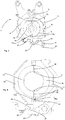
- FIG. 1 shows an illustration of a forming station 1 according to the invention.
- This forming station 1 has two side part carriers 4 and 6. These are pivotable with respect to one another and with respect to a main axis S. It is possible for both side part supports to be pivoted with respect to this main axis. It would also be possible for only one of the two side part supports to be pivoted with respect to the main axis. It would also be conceivable that two mutually parallel axes are provided, with respect to which the two side part carriers are pivoted. The main axis S or a corresponding pivot shaft here runs perpendicular to the plane of the figure.
- On the two blow mold carrier parts are each Shells 34 and 36 arranged. Blow mold side parts 14 and 16 are in turn arranged on these molded shells 34 and 36.
- reference numeral 20 denotes a locking mechanism which serves to lock the two side part carriers 4 and 6, in particular during a blowing process.
- a first locking element 22 is provided, which is fastened to the first side part carrier 4.
- a second locking element 24 is pivotally arranged on the second side part carrier.
- the reference numeral 41 denotes a lever arm by means of which the locking element 24 can be pivoted with respect to the pivot axis S1.
- the pivot axis S1 in turn is parallel to the main pivot axis S.
- a cam roller 43 can be provided with a guide curve (not shown) which is in particular stationary.
- other drives would also be conceivable, such as, in particular, electrical drives which serve to pivot the side part carriers.
- Figure 2 shows the forming station 1 in a state in which the side part carriers or the blow molding parts 14 and 16 are almost closed, but there is still no complete locking. It can be seen that the two locking elements 22 and 24 already engage in one another, but are not yet completely closed to one another. Opening the blow mold is no longer possible here.
- Figure 3 shows a representation of the forming station 1 in a not yet closed state.
- the two locking elements 22 and 24 do not yet interlock and the blow mold side parts 14 and 16 are still a clear gap open.
- the reference numerals 14a and 14b relate to contact surfaces of the first blow molded part and the reference symbols 16a and 16b relate to touch surfaces of the second blow molded part.
- the contact surfaces 14a and 16a and 14b and 16b lie against one another. The accuracy of this concern also determines the resulting form gap.
- the design of the locking elements therefore causes these two contact surfaces to be pressed against one another particularly precisely.
- Figure 4 again shows an enlarged view similar Figure 2 , Here the two locking elements 22 and 24 already interlock, but there is still no completely closed state. It can also be seen that the mold carrier shells 34 and 36 each form contact surfaces 42 and 44 with one another.
- the contact surface 42 has a projection 34a.
- the contact surface 44 has a recess 36a. These can interlock. This projection 34a and the recess 36a thus form a relatively large common contact surface with one another.
- first locking element has a contact surface 28 and the second locking element 24 has a second contact surface 26.
- Figure 5 shows a further representation in an almost closed state.
- the contact surfaces 26 and 28 can be seen, which cause the blow mold to be locked and the side part carriers to be moved towards one another.
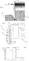
- Figure 6 shows a detailed view of the locking elements 122 and 124 according to the prior art. It can be seen that these are already touching each other in the position shown. In this way, there is no longer any gap here, which allows a certain play between the blow molded parts. Also, in the event of continued pivoting, no further advancement of the blow mold parts towards one another is achieved.
- FIG 7 shows a representation of two locking elements according to the invention. It can be seen here that the contact surfaces 26 and 28 each have essentially straight sections 26a and 28a. At the in Figure 4 shown state, a gap Sp is formed between the two contact surfaces 26 and 28. This can have a width, for example, between 0.1 mm and 0.5 mm, preferably between 0.15 mm and 0.35 mm and particularly preferably between 0.2 mm and 0.3 mm. While this gap is being built up, there is still a certain amount of play between the two locking elements with respect to one another and thus also with respect to the two side part carriers on which these locking elements are arranged. With a further movement, this gap becomes complete closed and the two locking elements are also pushed towards each other. In this way, the mold gap between the blow molded parts is closed.
- the reference numerals 23 and 25 each relate to recesses which are arranged in the two locking elements.
- Fig. 7a shows an enlarged view Fig. 7 , It can be seen here that the contact surface 28a is slightly inclined with respect to the gap Sp or the boundary line of the gap SP shown in the figure.
- the contact surface preferably has an angle a with respect to this gap or its (geometric) boundary line, which is between 1 ° and 20 °, preferably between 1 ° and 15 °, preferably between 1 ° and 10 ° and particularly preferably between 1 ° and 8 ° lies.
- the contact surface 28 In a completely pivoted-in state of the locking element, the contact surface 28 preferably lies flat against the contact surface 26.
- Figure 8 shows a further illustration of a side part carrier 4. It can be seen that here, in addition to the locking element 22 and the groove 53 formed thereby, in which the second locking element (not shown) engages, damping or prestressing elements 52 and 54 are provided. These prestressing elements 52, 54 likewise bring about a targeted closing of the blow mold when combined with the second side part carrier (not shown). These biasing elements can generate a force that presses the two side part carriers apart, but which is overcome by the force that is generated by the locking elements.
- the reference numeral 56 denotes holders on which a pivot shaft for pivoting the blow mold carrier part can be received.
- Figure 9 shows a side view of the in Figure 8 shown side part carrier. Here again, the locking element 22 is shown.
Landscapes
- Engineering & Computer Science (AREA)
- Manufacturing & Machinery (AREA)
- Mechanical Engineering (AREA)
- Moulds For Moulding Plastics Or The Like (AREA)
- Blow-Moulding Or Thermoforming Of Plastics Or The Like (AREA)
Description
- Die vorliegende Erfindung bezieht sich auf eine Umformungsstation zum Umformen von Kunststoffvorformlingen zu Kunststoffbehältnissen. Derartige Umformungsstationen, die Teile von Blasformmaschinen sein können werden verwendet, um Kunststoffflaschen herzustellen. Dabei werden erwärmte Kunststoffvorformlinge in Blasformen eingegeben und dort mittels Blasluft zu Kunststoffbehältnissen und insbesondere Kunststoffflaschen umgeformt. Zu diesem Zweck weisen diese Umformungsstationen üblicherweise Blasformträger auf, welche Teile von Blasformen tragen. Die Kunststoffvorformlinge werden in die Blasform eingegeben, diese wird geschlossen und anschließend erfolgt die Expansion des Kunststoffvorformlings.
- Dabei ist es aus dem Stand der Technik bekannt, dass insbesondere die Stellen, an denen sich die Seitenteile der Blasformen kontaktieren, bei der Herstellung der Kunststoffvorformlinge kritisch sind und bei der fertiggestellten Flasche Nahten erzeugen. Im Stand der Technik sind unterschiedliche Vorgehensweisen bekannt, um diese Nahten gering zu halten. Insbesondere sind unterschiedlichste Verriegelungsmechanismen der Blasformteile bzw. der Blasformträger bekannt.
- So sind Verriegelungstechniken bekannt, welche Verriegelungs-Wellensysteme, Magnetsysteme oder Stiftsysteme aufweisen. Üblicherweise werden jedoch nur die Formträgerhälften geschlossen und verriegelt, sodass hierdurch nicht unmittelbar ein bündiges und formschlüssiges Verriegeln der Formschalen bzw. der Blasformteile erreicht wird. So ist beispielsweise aus der
EP1 636 005 B1 eine derartige Vorrichtung bekannt, bei der (als Verriegelungseinrichtung) verdrehgesicherte Widerhaken bezüglich einander in der Längsrichtung verschoben werden um so einen Eingriff zu bewirken. Weitere Verriegelungstechnicken sind aus den DokumentenUS9050749B1 DE102012104754A1 undUS8721315B2 bekannt. - Um hierbei die Formspalte weiter zu verringern, ist es aus dem Stand der Technik bekannt, ein Druckkissensystem zu verwenden, wobei ein Blasformteil bei bereits geschlossener Blasform auf das andere mittels des Druckkissens zugedrückt wird. Die Notwendigkeit des Druckkissens zum bündigen und formbündigen Schließen der Blasform bedingt jedoch einen relativ hohen Aufwand, beispielsweise, um dieses Druckkissen mit Druckluft zu versorgen. Auch ist ein vergleichsweise hoher Aufwand zur Verschlauchung und hinsichtlich der Drucckissendichtung erforderlich. Daneben sind auch relativ hohe Prozesskosten erforderlich, um dieses Druckkissen anzusteuern und auch ein höherer störungstechnischer Aufwand sowie auch ein höherer Verschleiß.
- Der vorliegenden Erfindung liegt daher die Aufgabe zugrunde, sowohl die Herstellungs- als auch die Prozesskosten zu senken. Insbesondere soll der Aufwand, der zur Bereitstellung des besagten Druckkissens erforderlich ist, reduziert werden. Diese Aufgaben werden erfindungsgemäß durch die Gegenstände der unabhängigen Ansprüche erreicht. Vorteilhafte Ausführungsformen und Weiterbildungen sind Gegenstand der Unteransprüche.
- Eine erfindungsgemäße Umformungsstation zum Umformen von Kunststoffvorformlingen zu Kunststoffbehältnissen und insbesondere Kunststoffflaschen weist zwei Seitenteilträger auf, welche zum Tragen von Seitenteilen einer Blasform bestimmt sind. Weiterhin weist diese Umformungsstation bevorzugt einen Bodenteilträger zum Tragen eines Bodenteils der Blasform auf. Diese Seitenteile sowie das Bodenteil der Blasform bilden gemeinsam einen Hohlraum aus, innerhalb dessen die Kunststoffvorformlinge durch Beaufschlagung mit einem fließfähigen Medium und insbesondere mit Druckluft zu den Kunststoffbehältnissen umformbar sind.
- Weiterhin ist wenigstens einer der beiden Seitenteilträger zum Öffnen und/oder Schließen der Blasform gegenüber dem anderen Seitenteilträger bezüglich einer vorgegebenen Hauptachse schwenkbar. Weiterhin weist die Umformungsstation einen Verriegelungsmechanismus auf, um in einem geschlossenen Zustand der Blasform einen Seitenteilträger mit dem anderen Seitenteilträger (und/oder ein Blasformteil mit dem anderen und/oder ein Blasformschalenteil mit dem anderen Blasformschalenteil) zu verriegeln. Weiterhin weist der Verriegelungsmechanismus ein zweites Verriegelungselement auf, welches bezüglich einer vorgegebenen Schwenkachse schwenkbar ist und welches zum Verriegeln der Seitenteilträger mit einem ersten Verriegelungselement ineinandergreift.
- Erfindungsgemäß weist wenigstens eines der beiden Verriegelungselemente eine erste Kontaktoberfläche auf, welche dazu geeignet und bestimmt ist, beim Verriegeln mit dem ersten Verriegelungselement mit einer zweiten Kontaktoberfläche des ersten Verriegelungselements zusammenzuwirken, wobei wenigstens eine dieser Kontaktoberflächen derart ausgebildet ist, dass bei einem Schwenkvorgang des zweiten Verriegelungselements bezüglich der Schwenkachse in Richtung des ersten Verriegelungselements die beiden Seitenteilträger aufeinander zugedrängt werden.
- Es wird daher vorgeschlagen, dass der Verriegelungsmechanismus bzw. das Verriegelungselement so ausgebildet ist, dass zunächst ein arretierter Zustand zwischen den Seitenteilträgern entsteht, wobei hier noch ein gewisser Formspalt möglich ist. Bevorzugt wird durch eine weitere Schwenkbewegung des Verriegelungselements ein Blasformteil, beispielsweise eine Blasformhälfte auf das andere Blasformteil, insbesondere die andere Blasformhälfte, zugestellt. Damit bewirken die Verriegelungselemente bevorzugt nicht nur ein Verriegeln der Seitenteilträger, sondern darüber hinaus in Abhängigkeit von der Schwenkstellung auch, dass die beiden Blasformteile aufeinander zugedrängt werden. Auf diese Weise kann ein Formspalt zwischen den beiden Blasformseitenteilen verringert werden. Bevorzugt handelt es sich bei der Schwenkachse um welche das Verriegelungselement geschwenkt wird, um eine Schwenkachse, welche parallel zu einer Längsachse der umzuformenden Behältnisse verläuft.
- Die Erfindung beschreibt damit ein Verriegelungssystem einer Umformungsstation bzw. Blasformeinheit, welches bevorzugt zwei ineinander greifende Schließelemente bzw. Verriegelungselemente aufweist, wobei wenigstens ein Verriegelungselement drehbar gelagert ist. Mindestens eines dieser Schließelemente bzw. Verriegelungselemente weist dabei bevorzugt in einem Eingriffsbereich des zweiten Verriegelungselements eine Kontaktoberfläche und insbesondere einen Radius oder eine ähnliche Geometrie auf, welche vorab ein Schließen der Seitenteilträger gewährleistet und zudem, je nach Ausführung dieser Oberfläche oder der ähnlichen Geometrie, ein Heranziehen und bündiges und/oder formschlüssiges Verschließen der Formträgerhälften bzw. Seitenteilträger ermöglicht.
- Bevorzugt weist das jeweils andere Verriegelungselement ebenfalls eine entsprechende Oberfläche auf, welche auf die erstgenannte Oberfläche des ersten Verriegelungselements angepasst ist. Auf diese Weise wird eine Doppelfunktion erfüllt, nämlich die Seitenteilträger arretiert und zusätzlich ein bündiges und/oder formschlüssiges Verschließen der Formschalen und/oder der Blasformteile bewirkt. Durch dieses bündige Verschließen der Formschalen kann die Notwendigkeit eines Druckkissens entfallen, welches im Stand der Technik zum bündigen Schließen dieser Formschalen oder Blasformteile verwendet wurde, um die gewünschte Qualität der Trennnaht zu gewährleisten. Diese Qualität wird hier durch das bündige und/oder formschlüssige Heranziehen des jeweils anderen Seitenteilträgers gewährleistet. Auf diese Weise kann erreicht werden, dass die gesamte Druckkisseneinheit entfällt und auch kein Aufwand bezüglich einer Leckage des Druckkissens entsteht.
- Bevorzugt tritt auch eine verbesserte Selbsthemmung durch die Oberfläche, beispielsweise den Radius oder die ähnliche Geometrie, an zumindest einem der beiden Verriegelungselemente auf. Unter Selbsthemmung versteht man in der Mechanik den durch Reibung verursachten Widerstand gegen ein Verrutschen oder ein Verdrehen zweier aneinander liegender Körper. Sobald die Haftreibung überschritten ist, sind die Körper nicht mehr selbsthemmend. Die Selbsthemmung durch Größen wie den Neigungswinkel, die Oberflächenrauigkeit der Auflageflächen, die Werkstoffpaarung, die Gleitgeschwindigkeit, aber auch durch den Schmierstoff und die Erwärmung beeinflusst.
- Um Selbsthemmung zu erreichen, wird der resultierende Winkel kleiner als der Arcustangens der Haftreibungszahl ausgeführt. Wenn also im vorliegenden Beispiel der Winkel zwischen den Oberflächen bei 2,86° liegt würde sich zum Erreichen der Selbsthemmung eine Gleitreibungszahl von 0,05 ergeben (bzw. umgekehrt müsste bei einer Gleitreibungszahl von 0,05 der Winkel bei 2,86° (oder geringer) gewählt werden. Eine Gleitreibungszahl von 0,05 ist realistisch, wenn Stahl auf (geschmiertes) Stahl triff, wobei dies den hinsichtlich der Reibung ungünstigsten Zustand darstellt. Damit wird bevorzugt der Winkel zwischen den Oberflächen derart gewählt, dass die erwähnte Selbsthemmung auftritt.
- Bevorzugt werden keine zueinander ebenen Flächen vorgesehen, sondern eine leicht, insbesondere durch den Radius, gekrümmte Fläche. Dies erhöht zusätzlich die Sicherheit, da die gekrümmte Fläche wie ein "Wiederhaken" funktioniert.
- Auf diese Weise kann auch der Verschleiß verringert werden. Daneben ist auch kein steuerungstechnischer Aufwand vorhanden, um ein Druckkissen anzusteuern und insbesondere kann beispielsweise auf pneumatische Ventile verzichtet werden.
- Bei einer bevorzugten Ausführungsform werden bei einem Schwenkvorgang des zweiten Verriegelungselements in Richtung des ersten Verriegelungselements und bezüglich der Schwenkachse zunächst die beiden Seitenteilträger bezüglich einander arretiert und anschließend aufeinander zugedrängt. Dies kann dabei in der Weise erfolgen, dass bevorzugt zunächst bei einem Schwenkvorgang des zweiten Verriegelungselements um einen ersten Winkel ein Verriegelungselement das andere hintergreift und bei einem weiteren Schwenken in der gleichen Richtung bzw. in der gleichen Schwenkrichtung die beiden Seitenteile aufeinander zugedrängt werden. Bevorzugt findet also zunächst ein Eingriff statt, der die Umformungsstation in einem geschlossenen Zustand arretiert und erst anschließend ein Zustellen des einen Seitenteilträgers auf den anderen Seitenteilträger zu.
- Bei einer weiteren vorteilhaften Ausführungsform ist die Umformungsstation druckkissenfrei ausgebildet. Dies bedeutet, dass auf das Anbringen eines Druckkissens, beispielsweise zwischen dem Seitenteilträger und einer Formschale oder auch einer Formschale und dem Seitenteil der Blasform verzichtet wird. Vielmehr erfolgt die Bewegung, die ansonsten durch das Druckkissen ermöglicht wird, durch den beschriebenen Zustellvorgang, der während des Verriegelns durchgeführt wird. Bevorzugt bewirkt daher die Verriegelungsbewegung der Seitenteilträger auch ein Zustellen der beiden Seitenteile der Blasform aufeinander zu.
- Bei einer weiteren vorteilhaften Ausführungsform weist die Kontaktoberfläche eines Verriegelungselements einen gekrümmten und/oder schrägen Abschnitt auf, der mit der Kontaktoberfläche des anderen Verriegelungselements zusammenwirkt, um die beiden Seitenteilträger aufeinander zuzustellen. Bei diesem gekrümmten und/oder schrägen Abschnitt kann es sich um einen gekrümmten Abschnitt mit einem bestimmten Radius handeln und/oder auch um einen schrägen Abschnitt.
- Bevorzugt ist wenigstens ein Verriegelungselement hakenartig ausgebildet. Bevorzugt sind beide Verriegelungselemente hakenartig ausgebildet. Bevorzugt erstreckt sich wenigstens ein Verriegelungselement entlang der Richtung der Hauptachse. Bevorzugt erstrecken sich beide Verriegelungselemente entlang der Richtung der Hauptachse. Bevorzugt ist wenigstens ein Verriegelungselement kontinuierlich entlang der Hauptachse ausgebildet. Es wäre jedoch auch möglich, dass mehrere Verriegelungselemente entlang der Richtung der Hauptachse hintereinander und bevorzugt auch beabstandet zueinander angeordnet sind.
- Weiterhin weist die Vorrichtung bevorzugt eine Dämpfungs- und/oder Federungseinrichtung auf, welche bei einem Schließen der Blasform diese Schließbewegung dämpft. Diese Dämpfungseinrichtung ist dabei bevorzugt an wenigstens einem der beiden Seitenteilträger angeordnet. Bevorzugt weist die Vorrichtung zwei derartige Dämpfungs- und/oder Federungselemente auf. Besonders bevorzugt ist wenigstens ein Verriegelungselement in Richtung der Hauptachse zwischen diesen beiden Dämpfungs- und/oder Federungselementen angeordnet. Diese Dämpfungselemente können dabei ein elastisches Material und/oder ein Federelement aufweisen. Bevorzugt wirken diese Dämpfungs- und/oder Federungselemente einer Schließbewegung der Seitenteilträger entgegen.
- Bei einer weiteren vorteilhaften Ausführungsform sind das erste Verriegelungselement und das zweite Verriegelungselement derart ausgebildet, dass in einer vorgegebenen Schwenkstellung des zweiten Verriegelungselements gegenüber dem ersten Verriegelungselement sich die Kontaktoberflächen der beiden Verriegelungselements gegenüber stehen, jedoch ein Spalt zwischen den beiden Kontaktoberflächen ausgebildet ist.
- Hierbei handelt es sich um eine Stellung, in der die Blasform im Wesentlichen geschlossen ist, bzw. nicht mehr geöffnet werden kann, da dies dann durch die Kontaktoberflächen der beiden Verriegelungselemente verhindert wird. Der Spalt wird dabei bevorzugt in einer Umfangsrichtung der Schwenkbewegung der beiden Blasformträgerteile und/oder einer Umfangsrichtung der Schwenkbewegung des wenigstens einen Verriegelungselements ausgebildet. Bevorzugt überlappen sich die Kontaktoberflächen in einer Umfangsrichtung der Schwenkbewegung in dieser Position derart, dass beim Öffnen diese Kontaktoberflächen aneinander anstoßen würden.
- Bevorzugt überlappen sich die Kontaktoberflächen und/oder die Verriegelungselemente derart, dass ein Öffnen der Blasform eben durch diese Überlappung verhindert wird, insbesondere da bei einem Öffnen die Kontaktoberflächen aneinanderstoßen.
- Dies wird unter Bezugnahme auf die Figuren weiter erläutert. Dabei kann die Ausführung derart erfolgen, dass sich in dieser ersten Schwenkposition die beiden Verriegelungselemente gegenüber liegen, jedoch noch einen vorgegebenen Abstand bzw. Spalt zueinander aufweisen.
- Dieser Spalt kann sich dabei in einer radialen Richtung der Schwenkbewegung des wenigstens einen Blasformträgerteils erstrecken. Der besagte Spalt ermöglicht daher ein gewisses Spiel der Träger, bevor insgesamt die Blasformträgerteile geschlossen werden.
- Bei einer weiteren vorteilhaften Ausführungsform ist dieser besagte Spalt durch eine weitere Schwenkbewegung des zweiten Verriegelungselements verringerbar. Bei dieser weiteren Schwenkbewegung handelt es sich insbesondere um eine weitere Schwenkbewegung in Richtung eines vollständig verriegelten Zustands und/oder eine Schwenkbewegung, welche sich an die obige Schwenkbewegung, welche zu dem Überlappen zwischen den Verriegelungselementen führt, anschließt. Durch dieses Verringern des Formspalts wird damit die eine Kontaktoberfläche des einen Verriegelungselements auf die entsprechende zweite Kontaktoberfläche des ersten Verriegelungselements zugestellt und kontaktiert diese schließlich. Bei einer weiteren Bewegung können weiter die beiden Blasformträgerteile noch weiter aufeinander zugestellt werden.
- Damit wird der Spalt durch eine weitere Schwenkbewegung des zweiten Verriegelungselements geschlossen. Bevorzugt erstreckt sich der oben erwähnte Spalt ebenfalls in Richtung der Hauptachse.
- Bei einer weiteren vorteilhaften Ausführungsform weisen die Seitenteile und/oder die die Seitenteile tragenden Formschalen einander flächig kontaktierende Kontaktieroberflächen auf. Durch diese Ausgestaltung können die Formschalen und/oder die Seitenteile bündig mit einer flächigen Kontaktieroberfläche aneinandergelegt werden, sodass der Formspalt zwischen den Seitenteilen gering gehalten werden kann.
- Bei einer weiteren vorteilhaften Ausführungsform weist wenigstens eine dieser Kontaktieroberflächen einen sich in Richtung der Hauptachse erstreckenden Vorsprung auf. Dabei kann es sich beispielsweise um einen gekrümmten oder nasenartigen Vorsprung handeln.
- Bei einer weiteren vorteilhaften Ausführungsform weist die andere dieser Kontaktieroberflächen eine sich in Richtung der Hauptachse erstreckende Ausnehmung auf, welche besonders bevorzugt an den genannten Vorsprung angepasst ist. Dabei kann in einem geschlossenen Zustand der Blasform der Vorsprung in der Ausnehmung liegen. Auf diese Weise wird eine sehr exakte Zentrierung der beiden Blasformseitenteile und/oder der Formschalen bewirkt.
- Bei einer weiteren vorteilhaften Ausführungsform ist wenigstens eine der Kontaktoberflächen der Verriegelungselemente eine gehärtete Kontaktoberfläche. Vorteilhaft handelt es sich bei beiden Kontaktoberflächen um gehärtete Kontaktoberflächen. Auf diese Weise kann einer schnellen Abnutzung dieser Kontaktieroberflächen, welche vergleichsweise hohe Kräfte aufnehmen müssen, vermieden werden.
- Die vorliegende Erfindung ist weiter auf eine Vorrichtung zum Umformen von Kunststoffvorformlingen zu Kunststoffbehältnissen gerichtet, wobei diese Vorrichtung einen bewegbaren und insbesondere drehbaren Träger aufweist, an den eine Vielzahl der oben beschriebenen Umformungsstationen angeordnet ist. Vorteilhaft weisen die Umformungsstationen jeweils stangenartige Körper auf, welche in die Kunststoffvorformlinge einführbar sind, um diese in deren Längsrichtung zu dehnen.
- Bei einer weiteren vorteilhaften Ausführungsform weisen die Umformungsstationen jeweils Beaufschlagungseinrichtungen auf, um die Kunststoffvorformlinge mit einem fließfähigen und insbesondere gasförmigen Medium zu beaufschlagen. Bei diesen Beaufschlagungseinrichtungen kann es sich beispielsweise um Blasdüsen handeln, welche an einen Mündungsrand der Kunststoffvorformlinge anlegbar sind.
- Bei einer weiteren vorteilhaften Ausführungsform weist die oben beschriebene Umformungsstation auch einen Bodenteilträger auf, der zum Schließen der Blasform mit den beschriebenen Seitenteilträgern arretierbar ist.
- Die vorliegende Erfindung ist weiterhin auf ein Verfahren zum Schließen einer Umformungsstation zum Umformen von Kunststoffvorformlingen zu Kunststoffbehältnissen gerichtet. Dabei weist die Umformungsstation zwei Seitenteilträger zum Tragen von Seitenteilen einer Blasform auf, sowie bevorzugt auch einen Bodenteilträger zum Tragen eines Bodenteils der Blasform. Dabei bilden diese Seitenteile und das Bodenteil der Blasform gemeinsam einen Hohlraum aus, innerhalb dessen die Kunststoffvorformlinge durch Beaufschlagung mit einem fließfähigen und insbesondere gasförmigen Medium zu den Kunststoffbehältnissen umgeformt werden.
- Dabei wird wenigstens einer der beiden Seitenteilträger zum Schließen der Blasform gegenüber dem anderen Seitenteilträger bezüglich einer vorgegebenen Hauptachse geschwenkt und die Umformungsstation weist weiterhin einen Verriegelungsmechanismus auf, um in einem geschlossenen Zustand der Blasform einen Seitenteilträger mit dem anderen Seitenteilträger zu verriegeln. Weiterhin weist der Verriegelungsmechanismus ein zweites Verriegelungselement auf, welches bezüglich einer vorgegebenen Schwenkachse geschwenkt wird und welches zum Verriegeln der Seitenteilträger mit einem ersten Verriegelungselement ineinandergreift.
- Erfindungsgemäß weist wenigstens eines der beiden Verriegelungselemente eine erste Kontaktoberfläche auf, welche dazu geeignet ist, beim Verriegeln mit dem ersten Verriegelungselement mit einer zweiten Kontaktoberfläche des ersten Verriegelungselements zusammenzuwirken, wobei wenigstens eine dieser Kontaktoberflächen derart ausgebildet ist, dass bei einem Schwenkvorgang des zweiten Verriegelungselements bezüglich der Schwenkachse in Richtung des ersten Verriegelungselements die beiden Seitenteilträger aufeinander zugedrängt werden.
- Es wird daher auch verfahrensseitig vorgeschlagen, dass mittels der Verriegelungselemente zunächst ein Verriegeln bzw. Arretieren der Blasformträgerteile erfolgt, wobei hier noch ein gewisser Spalt bzw. ein gewisses Spiel in der Schwenkbewegung ermöglicht wird. Durch eine weitere Zustellung des Verriegelungselements wird dieser Spalt geschlossen und bevorzugt werden auch die Blasformteile aufeinander zugedrängt. Bevorzugt findet auch hier der eigentliche Expansionsvorgang der Kunststoffvorformlinge ohne die Verwendung eines Druckkissens statt. Bevorzugt ist wird eine Umformungsstation der oben beschriebenen Art für das Verfahren verwendet.
- Weitere Vorteile und Ausführungsformen ergeben sich aus den beigefügten Zeichnungen. Darin zeigen:
- Fig. 1
- Eine schematische Darstellung einer Umformungsstation;
- Fig. 2
- eine Darstellung einer Umformungsstation in einem noch nicht vollständig geschlossenen Zustand, wobei jedoch eine Arretierung der Seitenteilträger vorliegt;
- Fig. 3
- eine Darstellung der Umformungsstation in einem noch nicht verriegelten Zustand;
- Fig. 4
- eine Detaildarstellung des Verriegelungsmechanismus in einem arretierten, jedoch noch nicht vollständig verriegelten Zustand;
- Fig. 5
- eine weitere Detaildarstellung einer Umformungsstation in dem arretierten, jedoch noch nicht vollständig verriegelten Zustand;
- Fig. 6
- eine Darstellung zweier Verriegelungselemente nach dem Stand der Technik;
- Fig. 7
- eine Darstellung zweier erfindungsgemäßer Verriegelungselemente;
- Fig. 7a
- eine vergrößerte Ansicht der in
Fig. 7 gezeigten Darstellung; - Fig. 8
- eine Darstellung eines Seitenteilträgers für eine Blasform; und
- Fig. 9
- eine Seitenansicht des in
Fig. 8 gezeigten Seitenteilträgers. -
Figur 1 zeigt eine Darstellung einer erfindungsgemäßen Umformungsstation 1. Diese Umformungsstation 1 weist zwei Seitenteilträger 4 und 6 auf. Diese sind bezüglich einander und bezüglich einer Hauptachse S schwenkbar. Dabei ist es möglich, dass beide Seitenteilträger bezüglich dieser Hauptachse geschwenkt werden. Auch wäre es möglich, dass nur einer der beiden Seitenteilträger gegenüber der Hauptachse geschwenkt wird. Auch wäre es denkbar, dass zwei zueinander parallele Achsen vorgesehen sind, bezüglich derer die beiden Seitenteilträger geschwenkt werden. Die Hauptachse S bzw. eine entsprechende Schwenkwelle verläuft hier senkrecht zu der Figurenebene. An den beiden Blasformträgerteilen sind jeweils Formschalen 34 und 36 angeordnet. An diesen Formschalen 34 und 36 wiederum sind Blasformseitenteile 14 und 16 angeordnet. - Das Bezugszeichen 20 kennzeichnet in seiner Gesamtheit einen Verriegelungsmechanismus, der zum Verriegeln der beiden Seitenteilträger 4 und 6 insbesondere während eines Blasvorgangs dient. Zu diesem Zweck ist ein erstes Verriegelungselement 22 vorgesehen, welches an dem ersten Seitenteilträger 4 befestigt ist. Ein zweites Verriegelungselement 24 ist schwenkbar an dem zweiten Seitenteilträger angeordnet. Dabei ist insbesondere eine Schwenkung dieses zweiten Verriegelungselements 24 bezüglich einer Schwenkachse S1 möglich. Das Bezugszeichen 41 kennzeichnet einen Hebelarm, mittels dessen die Verschwenkung des Verriegelungselements 24 bezüglich der Schwenkachse S1 erreicht werden kann. Die Schwenkachse S1 wiederum ist parallel zu der Hauptschwenkachse S. Zum Schwenken des Verriegelungselements kann eine Kurvenrolle 43 vorgesehen sein mit einer insbesondere stationären (nicht gezeigten) Führungskurve. Daneben wären jedoch auch andere Antriebe denkbar, wie insbesondere elektrische Antriebe, welche zum Schwenken der Seitenteilträger dienen.
-
Figur 2 zeigt die Umformungsstation 1 in einem Zustand, in dem die Seitenteilträger bzw. die Blasformteile 14 und 16 nahezu geschlossen sind, jedoch noch keine vollständige Verriegelung vorliegt. Dabei erkennt man, dass die beiden Verriegelungselemente 22 und 24 zwar schon ineinander greifen, jedoch noch nicht vollständig miteinander verschlossen sind. Ein Öffnen der Blasform ist jedoch hier nicht mehr möglich. -
Figur 3 zeigt eine Darstellung der Umformungsstation 1 in einem noch nicht geschlossenen Zustand. Hier greifen die beiden Verriegelungselemente 22 und 24 noch nicht ineinander und die Blasformseitenteile 14 und 16 sind noch einen deutlichen Spalt geöffnet. Die Bezugszeichen 14a und 14b beziehen sich auf Berühroberflächen des ersten Blasformteils und die Bezugszeichen 16a und 16b auf Berühroberflächen des zweiten Blasformteils. In einem geschlossenen Zustand der Blasform liegen die Kontaktoberflächen 14a und 16a sowie 14b und 16b aneinander. Durch die Genauigkeit dieses Anliegens wird auch der entstehende Formspalt bestimmt. Die Ausgestaltung der Verriegelungselemente bewirkt daher, dass diese beiden Kontaktoberflächen besonders präzise aneinander gedrückt werden. -
Figur 4 zeigt wiederum eine vergrößerte Darstellung ähnlichFigur 2 . Hier greifen zwar die beiden Verriegelungselemente 22 und 24 schon ineinander, es liegt jedoch noch kein vollkommen geschlossener Zustand vor. Man erkennt weiterhin, dass die Formträgerschalen 34 und 36 jeweils Kontaktflächen 42 und 44 miteinander ausbilden. Dabei weist die Kontaktfläche 42 einen Vorsprung 34a auf. Die Kontaktfläche 44 weist eine Ausnehmung 36a auf. Diese können dabei ineinander eingreifen. Dieser Vorsprung 34a und die Ausnehmung 36a bilden damit eine relativ große gemeinsame Kontaktoberfläche miteinander aus. - Weiterhin weist das erste Verriegelungselement eine Kontaktoberfläche 28 auf und das zweite Verriegelungselement 24 eine zweite Kontaktoberfläche 26. Diese wirken, wie ebenfalls unten genauer dargestellt, miteinander, sodass zunächst eine Arretierung der Seitenteilträger und später dann auch ein Zustellen der beiden Seitenteilträger aufeinander zu und damit auch eine Minimierung des Formspalts erreicht wird.
-
Figur 5 zeigt eine weitere Darstellung in einem nahezu geschlossenen Zustand. Auch hier erkennt man wieder die Kontaktoberflächen 26 und 28, die ein Verriegeln der Blasform sowie auch das Aufeinanderzubewegen der Seitenteilträger bewirken. -
Figur 6 zeigt eine Detaildarstellung der Verriegelungselemente 122 und 124 nach dem Stand der Technik. Man erkennt, dass diese sich bereits in der gezeigten Stellung einander berühren. Auf diese Weise ist hier kein Spalt mehr ausgebildet, der ein gewisses Spiel zwischen den Blasformteilen ermöglicht. Auch wird so bei einem weiter fortgesetzten Schwenken kein weiteres Zustellen der Blasformteile aufeinander zu mehr erreicht. -
Figur 7 zeigt eine Darstellung zweier erfindungsgemäßer Verriegelungselemente. Man erkennt hier, dass die Kontaktoberflächen 26 und 28 jeweils im Wesentlichen geradlinige Abschnitte 26a und 28a aufweisen. Bei dem inFigur 4 gezeigten Zustand wird zwischen den beiden Kontaktoberflächen 26 und 28 ein Spalt Sp ausgebildet. Dieser kann eine Breite beispielsweise zwischen 0,1 mm und 0,5 mm, bevorzugt zwischen 0,15 mm und 0,35 mm und besonders bevorzugt zwischen 0,2 mm und 0,3 mm aufweisen. Während dieser Spalt aufgebaut wird, besteht damit noch ein gewisses Spiel der beiden Verriegelungselemente bezüglich einander und damit auch hinsichtlich der beiden Seitenteilträger, an denen diese Verriegelungselemente angeordnet sind. Bei einer weiteren Bewegung wird dieser Spalt vollständig geschlossen und die beiden Verriegelungselemente werden auch aufeinander zugedrängt. Auf diese Weise wird auch der Formspalt zwischen den Blasformteilen geschlossen. - Die Bezugszeichen 23 und 25 beziehen sich jeweils auf Ausnehmungen, die in den beiden Verriegelungselementen angeordnet sind.
-
Fig. 7a zeigt eine Vergrößerung der Darstellung ausFig. 7 . Man erkennt hier dass die Kontaktoberfläche 28a leicht schräg gestellt ist gegenüber dem Spalt Sp bzw. der in der Figur eingezeichneten Begrenzungslinie des Spalts SP. Bevorzugt weist die Kontaktoberfläche gegenüber diesem Spalt bzw. dessen (geometrischer) Begrenzungslinie einen Winkel a auf, der zwischen 1° und 20°, bevorzugt zwischen 1° und 15°, bevorzugt zwischen 1° und 10° und besonders bevorzugt zwischen 1° und 8° liegt. Bevorzugt liegt in einem vollständig eingeschwenkten Zustand des Verriegelungselements die Kontaktoberfläche 28 flächig an der Kontaktoberfläche 26 an. -
Figur 8 zeigt eine weitere Darstellung eines Seitenteilträgers 4. Man erkennt, dass hier neben dem Verriegelungselement 22 und der hierdurch ausgebildeten Nut 53, in welche das zweite Verriegelungselement (nicht gezeigt) eingreift, auch Dämpfungs- bzw. Vorspannelemente 52 und 54 vorgesehen sind. Diese Vorspannelemente 52, 54 bewirken ebenfalls bei einem Zusammenschluss mit dem zweiten (nicht gezeigten) Seitenteilträger ein gezieltes Schließen der Blasform. Diese Vorspannelemente können dabei eine Kraft erzeugen, welche die beiden Seitenteilträger auseinander drückt, welche aber durch diejenige Kraft, welche von den Verriegelungselementen erzeugt wird überwunden wird. Das Bezugszeichen 56 kennzeichnet Halterungen, an denen eine Schwenkwelle zum Schwenken des Blasformträgerteils aufgenommen werden kann. -
Figur 9 zeigt eine Seitenansicht des inFigur 8 gezeigten Seitenteilträgers. Dabei ist auch hier wiederum das Verriegelungselement 22 dargestellt. -
- 1
- Umformungsstation
- 4,6
- Seitenteilträger
- 14, 16
- Blasformseitenteile
- 20
- Verriegelungsmechanismus
- 22
- erstes Verriegelungselement
- 23, 25
- Ausnehmung
- 24
- zweites Verriegelungselement
- 26, 28
- Kontaktoberflächen
- 26a, 28a
- geradlinige Abschnitte
- 34, 36
- Formschalen
- 34a
- Vorsprung
- 36a
- Ausnehmung
- 41
- Hebelarm
- 42, 44
- Kontaktflächen
- 43
- Kurvenrolle
- 52, 54
- Vorspannelemente
- 53
- Nut
- 56
- Halterungen
- 122, 124
- Verriegelungselemente Stand der Technik)
- S
- Hauptschwenkachse
- S1
- Schwenkachse
- a
- Winkel zwischen Spalt und Kontaktoberfläche
- Sp
- Spalt
Claims (9)
- Umformungsstation (1) zum Umformen von Kunststoffvorformlingen (10) zu Kunststoffbehältnissen wobei die Umformungsstation (1) zwei Seitenteilträger (4, 6) zum Tragen von Seitenteilen (14, 16) einer Blasform aufweist sowie bevorzugt einen Bodenteilträger zum Tragen eines Bodenteils der Blasform, wobei diese Seitenteile (14, 16) und das Bodenteil (18) der Blasform gemeinsam einen Hohlraum (15) ausbilden, innerhalb dessen die Kunststoffvorformlinge (10) durch Beaufschlagung mit einem fließförmigen Medium zu den Kunststoffbehältnissen umformbar sind, wobei wenigstens einer der beiden Seitenteilträger zum Öffnen und/oder Schließen der Blasform gegenüber dem anderen Seitenteilträger bezüglich einer vorgegebenen Hauptachse (S) schwenkbar ist und wobei die Umformungsstation einen Verriegelungsmechanismus aufweist, um in einem geschlossenen Zustand der Blasform einen Seitenteilträger (4) mit dem anderen Seitenteilträger (6) zu verriegeln und wobei der Verriegelungsmechanismus (20) ein zweites Verriegelungselement (24) aufweist, welches bezüglich einer vorgegebenen Schwenkachse (S1) schwenkbar ist und welches zum Verriegeln der Seitenteilträger mit einem ersten Verriegelungselement (22) ineinander greift und wenigstens eines der beiden Verriegelungselemente eine erste Kontaktoberfläche (26) aufweist, welche dazu geeignet ist, beim Verriegeln mit dem ersten Verriegelungselement (22) mit einer zweiten Kontaktoberfläche (28) des ersten Verriegelungselements (22) zusammenzuwirken, wobei wenigstens eine dieser Kontaktoberflächen derart ausgebildet ist, dass bei einem Schwenkvorgang des zweiten Verriegelungselements (24) bezüglich der Schwenkachse (S1) in Richtung des ersten Verriegelungselements (22) die beiden Seitenteilträger (4, 6) aufeinander zu gedrängt werden,
dadurch gekennzeichnet, dass
das erste Verriegelungselement (22) und das zweite Verriegelungselement (24) derart ausgebildet sind, dass in einer vorgegebenen Schwenkstellung des zweiten Verriegelungselements (24) gegenüber dem ersten Verriegelungselement (22) sich die Kontaktoberflächen (26, 28) der beiden Verriegelungselemente (22, 24) gegenüberstehen, jedoch ein Spalt (Sp) zwischen den beiden Kontaktoberflächen (26, 28) ausgebildet ist, wobei es sich hierbei um eine Stellung handelt, in der die Umformungsstation im Wesentlichen geschlossen ist und nicht mehr geöffnet werden kann und die Umformungsstation druckkissenfrei ausgebildet ist. - Umformungsstation (1) nach Anspruch 1,
dadurch gekennzeichnet, dass
bei dem Schwenkvorgang des zweiten Verriegelungselements (24) in Richtung des ersten Verriegelungselements (22) zunächst die beiden Seitenteilträger (4, 6) bezüglich einander arretiert und anschließend aufeinander zugedrängt werden. - Umformungsstation nach wenigstens einem der vorangegangenen Ansprüche,
dadurch gekennzeichnet, dass
die Kontaktoberfläche (26, 28) eines Verriegelungselements (22, 24) einen gekrümmten und/oder schrägen Abschnitt (26a) aufweist, der mit der Kontaktoberfläche (28, 26) des anderen Verriegelungselements (24, 22) zusammenwirkt, um die beiden Seitenteilträger aufeinander zuzustellen. - Umformungsstation nach Anspruch 1,
dadurch gekennzeichnet, dass
der Spalt (Sp) durch eine weitere Schwenkbewegung des zweiten Verriegelungselements (24) gegenüber dem anderen Verriegelungselement (22) verringerbar ist. - Umformungsstation nach wenigstens einem der vorangegangenen Ansprüche,
dadurch gekennzeichnet, dass
die Seitenteile (14, 16) und/oder die Seitenteile (14, 16) tragende Formschalen (34, 36) einander flächig kontaktierende Kontaktieroberflächen (34a, 36a) aufweisen. - Umformungsstation nach Anspruch 5,
dadurch gekennzeichnet, dass
wenigstens eine dieser Kontaktoberflächen einen sich in Richtung der Hauptachse (S) erstreckenden Vorsprung (42) aufweist. - Umformungsstation nach Anspruch 6,
dadurch gekennzeichnet, dass
die andere dieser Kontaktoberflächen (36a, 34a) eine sich in Richtung der Hauptachse erstreckende Ausnehmung (44) aufweist, welche geometrisch derart an den Vorsprung (42) angepasst ist. - Umformungsstation nach wenigstens einem der vorangegangenen Ansprüche,
dadurch gekennzeichnet, dass
wenisgtens eine der Kontaktoberflächen der Verriegelungselemente (22, 24) eine gehärtete Kontaktoberfläche ist. - Verfahren zum Schließen einer Umformungsstation zum Umformen von Kunststoffvorformlingen (10) zu Kunststoffbehältnissen wobei die Umformungsstation (1) zwei Seitenteilträger (4, 6) zum Tragen von Seitenteilen (14, 16) einer Blasform aufweist sowie bevorzugt einen Bodenteilträger zum Tragen eines Bodenteils der Blasform, wobei diese Seitenteile (14, 16) und das Bodenteil (18) der Blasform gemeinsam einen Hohlraum (15) ausbilden, innerhalb dessen die Kunststoffvorformlinge (10) durch Beaufschlagung mit einem fließförmigen Medium zu den Kunststoffbehältnissen umgeformt werden, wobei wenigstens einer der beiden Seitenteilträger zum Schließen der Blasform gegenüber dem anderen Seitenteilträger bezüglich einer vorgegebenen Hauptachse (S) geschwenkt wird und wobei die Umformungsstation einen Verriegelungsmechanismus aufweist, um in einem geschlossenen Zustand der Blasform einen Seitenteilträger (4) mit dem anderen Seitenteilträger (6) zu verriegeln und wobei der Verriegelungsmechanismus (20) ein zweites Verriegelungselement (24) aufweist, welches bezüglich einer vorgegebenen Schwenkachse (S1) geschwenkt und welches zum Verriegeln der Seitenteilträger mit einem ersten Verriegelungselement (22) ineinander greift, wobei wenigstens eines der beiden Verriegelungselemente eine erste Kontaktoberfläche (26) aufweist, welche dazu geeignet ist, beim Verriegeln mit dem ersten Verriegelungselement (22) mit einer zweiten Kontaktoberfläche (28) des ersten Verriegelungselements (22) zusammenzuwirken, wobei wenigstens eine dieser Kontaktoberflächen derart ausgebildet ist, dass bei einem Schwenkvorgang des zweiten Verriegelungselements (24) bezüglich der Schwenkachse (S1) in Richtung des ersten Verriegelungselements (22) die beiden Seitenteilträger (4, 6) aufeinander zu gedrängt werden
dadurch gekennzeichnet, dass
das erste Verriegelungselement (22) und das zweite Verriegelungselement (24) derart ausgebildet sind, dass in einer vorgegebenen Schwenkstellung des zweiten Verriegelungselements (24) gegenüber dem ersten Verriegelungselement (22) sich die Kontaktoberflächen (26, 28) der beiden Verriegelungselemente (22, 24) gegenüberstehen, jedoch ein Spalt (Sp) zwischen den beiden Kontaktoberflächen (26, 28) ausgebildet ist, wobei es sich hierbei um eine Stellung handelt, in der die Umformungsstation im Wesentlichen geschlossen ist und nicht mehr geöffnet werden kann und die Umformungsstation druckkissenfrei ausgebildet ist.
Applications Claiming Priority (2)
| Application Number | Priority Date | Filing Date | Title |
|---|---|---|---|
| DE102016105857.2A DE102016105857A1 (de) | 2016-03-31 | 2016-03-31 | Umformungsstation für Blasformmaschinen ohne Druckkissen |
| PCT/EP2017/050014 WO2017167461A1 (de) | 2016-03-31 | 2017-01-02 | Umformungsstation für blasformmaschinen ohne druckkissen |
Publications (2)
| Publication Number | Publication Date |
|---|---|
| EP3294525A1 EP3294525A1 (de) | 2018-03-21 |
| EP3294525B1 true EP3294525B1 (de) | 2020-02-19 |
Family
ID=57714613
Family Applications (1)
| Application Number | Title | Priority Date | Filing Date |
|---|---|---|---|
| EP17700013.0A Active EP3294525B1 (de) | 2016-03-31 | 2017-01-02 | Umformungsstation für blasformmaschinen ohne druckkissen |
Country Status (5)
| Country | Link |
|---|---|
| US (1) | US10513074B2 (de) |
| EP (1) | EP3294525B1 (de) |
| CN (1) | CN109070434B (de) |
| DE (2) | DE102016105857A1 (de) |
| WO (1) | WO2017167461A1 (de) |
Cited By (2)
| Publication number | Priority date | Publication date | Assignee | Title |
|---|---|---|---|---|
| EP4414154A1 (de) | 2023-02-13 | 2024-08-14 | KHS GmbH | Blasformeinheit für eine blasformanlage |
| EP4414155A1 (de) | 2023-02-13 | 2024-08-14 | KHS GmbH | Blasformeinheit für eine blasformanlage |
Families Citing this family (7)
| Publication number | Priority date | Publication date | Assignee | Title |
|---|---|---|---|---|
| IT201900006961A1 (it) * | 2019-05-17 | 2020-11-17 | Sipa Progettazione Automaz | Apparato di supporto per supportare almeno uno stampo di collo di contenitore in una macchina di stampaggio per iniezione e soffiaggio |
| CN110696332A (zh) * | 2019-07-18 | 2020-01-17 | 江苏辉河包装机械有限公司 | 一种旋转式吹瓶机的模壳开闭锁机构 |
| FR3101010B1 (fr) * | 2019-09-19 | 2021-09-10 | Sidel Participations | Unité de moulage à verrouillage par crochets |
| DE102019126948A1 (de) * | 2019-10-08 | 2021-04-08 | Krones Aktiengesellschaft | Vorrichtung und Verfahren zum Umformen von Kunststoffvorformlingen zu Kunststoffbehältnissen und Blasform |
| FR3115228B1 (fr) * | 2020-10-15 | 2023-05-12 | Sidel Participations | Moule de fabrication de corps creux en matière plastique |
| DE102021119052A1 (de) * | 2021-07-22 | 2023-01-26 | Khs Gmbh | Formwerkzeug zum Formen eines Behälters |
| CN119928226A (zh) * | 2025-02-27 | 2025-05-06 | 江苏新美星包装机械股份有限公司 | 一种带开闭锁机构的吹瓶机 |
Citations (2)
| Publication number | Priority date | Publication date | Assignee | Title |
|---|---|---|---|---|
| DE102012104754A1 (de) * | 2012-06-01 | 2013-12-05 | Krones Ag | Blasformmaschine mit umlaufender Verriegelungskurve |
| US8721315B2 (en) * | 2010-09-13 | 2014-05-13 | Amcor Limited | Method of handling liquid to prevent machine contamination during filling |
Family Cites Families (8)
| Publication number | Priority date | Publication date | Assignee | Title |
|---|---|---|---|---|
| US2006056A (en) * | 1929-11-16 | 1935-06-25 | Capstan Glass Co | Ring holder lock |
| US2485452A (en) * | 1945-03-08 | 1949-10-18 | Briggs Mfg Co | Press |
| US3652751A (en) * | 1969-06-20 | 1972-03-28 | Owens Illinois Inc | Method and apparatus for blow molding plastic articles |
| US3825396A (en) * | 1973-03-07 | 1974-07-23 | Owens Illinois Inc | Blow mold latching mechanism including a safety feature |
| FR2856334B1 (fr) * | 2003-06-19 | 2005-08-26 | Sidel Sa | Dispositif de moulage pour la fabrication de recipients en materiau thermoplastique |
| FR2856333B1 (fr) | 2003-06-19 | 2005-08-26 | Sidel Sa | Dispositif de moulage pour la fabrication de recipients en materiau thermoplastique |
| US9050749B1 (en) * | 2014-01-10 | 2015-06-09 | Chumpower Machinery Corp. | Blow molding device for a rotary bottle blowing machine |
| MA39005A (fr) * | 2014-05-09 | 2017-08-29 | Smi Spa | Machine pour le moulage par soufflage ou le moulage par étirage-soufflage de bouteilles dans un matériau polymère |
-
2016
- 2016-03-31 DE DE102016105857.2A patent/DE102016105857A1/de not_active Withdrawn
- 2016-03-31 DE DE202016008463.2U patent/DE202016008463U1/de not_active Expired - Lifetime
-
2017
- 2017-01-02 EP EP17700013.0A patent/EP3294525B1/de active Active
- 2017-01-02 CN CN201780000769.5A patent/CN109070434B/zh active Active
- 2017-01-02 US US15/546,354 patent/US10513074B2/en active Active
- 2017-01-02 WO PCT/EP2017/050014 patent/WO2017167461A1/de not_active Ceased
Patent Citations (2)
| Publication number | Priority date | Publication date | Assignee | Title |
|---|---|---|---|---|
| US8721315B2 (en) * | 2010-09-13 | 2014-05-13 | Amcor Limited | Method of handling liquid to prevent machine contamination during filling |
| DE102012104754A1 (de) * | 2012-06-01 | 2013-12-05 | Krones Ag | Blasformmaschine mit umlaufender Verriegelungskurve |
Cited By (4)
| Publication number | Priority date | Publication date | Assignee | Title |
|---|---|---|---|---|
| EP4414154A1 (de) | 2023-02-13 | 2024-08-14 | KHS GmbH | Blasformeinheit für eine blasformanlage |
| EP4414155A1 (de) | 2023-02-13 | 2024-08-14 | KHS GmbH | Blasformeinheit für eine blasformanlage |
| DE102023103378A1 (de) | 2023-02-13 | 2024-08-14 | Khs Gmbh | Blasformeinheit für eine Blasformanlage |
| DE102023103372A1 (de) | 2023-02-13 | 2024-08-14 | Khs Gmbh | Blasformeinheit für eine Blasformanlage |
Also Published As
| Publication number | Publication date |
|---|---|
| WO2017167461A1 (de) | 2017-10-05 |
| DE102016105857A1 (de) | 2017-10-05 |
| EP3294525A1 (de) | 2018-03-21 |
| US10513074B2 (en) | 2019-12-24 |
| DE202016008463U1 (de) | 2018-01-29 |
| CN109070434B (zh) | 2020-12-04 |
| CN109070434A (zh) | 2018-12-21 |
| US20190009451A1 (en) | 2019-01-10 |
Similar Documents
| Publication | Publication Date | Title |
|---|---|---|
| WO2017167461A1 (de) | Umformungsstation für blasformmaschinen ohne druckkissen | |
| EP2253454B1 (de) | Vorrichtung und Verfahren zum Temperieren von Kunststoffvorformlingen | |
| EP0565917B1 (de) | Vorrichtung zur Blasformung | |
| EP1789247B1 (de) | Vorrichtung zur blasformung von behältern | |
| EP2218569B1 (de) | Vorrichtung zum Herstellen von Kunststoffbehältnissen | |
| EP2493674B1 (de) | Vorrichtung zur handhabung von werkstücken | |
| EP2753465B1 (de) | Vorrichtung zum transport von vorformlingen für das blasformen von behältern | |
| WO2020078603A1 (de) | Teilungswechselstern zum transportieren und übergeben von behältern | |
| EP2740582B1 (de) | Blasformmaschine und Blasformverfahren. | |
| DE102005011805A1 (de) | Verfahren und Vorrichtung zur Blasformung von Behältern | |
| EP2522484B1 (de) | Vorrichtung und Verfahren zum Umformen von Kunststoffvorformlingen zu Kunststoffbehältnissen mit magnetisch betätigter Verriegelung | |
| EP3294526A1 (de) | Verfahren zur inhomogenen temperierung von vorformlingen | |
| DE202016101701U1 (de) | Umformungsstation für Blasformmaschinen ohne Druckkissen | |
| EP2368692B2 (de) | Blasformanordnung mit kontrolliertem Verriegelungsmechanismus | |
| DE10354506A1 (de) | Vorrichtung zur Blasformung von Behältern | |
| WO2012130374A1 (de) | Verfahren und vorrichtung zur herstellung von behältern | |
| EP2913174B1 (de) | Blasformmaschine mit Zentrierung des Blasformbodens | |
| EP3527350A2 (de) | Blasform | |
| DE10027111B4 (de) | Blasform und Verfahren zum Schließen einer Blasform | |
| EP1350612A1 (de) | Vorrichtung zur Handhabung von Vorformling / Behältern mittel separat ansteuerbaren Armen, die auf einer Drehscheibe radial befestigt sind | |
| DE202013101048U1 (de) | Vorrichtung zum Behandeln von Behältnissen mit Kunststoffführungsrollen aus Polyamidimid | |
| DE2454134A1 (de) | Blasform- und streckverfahren zur herstellung von hohlen kunststoffartikeln und vorrichtung zur durchfuehrung des verfahrens | |
| EP1254015B1 (de) | Verfahren und vorrichtung zum transport von tragelementen | |
| EP3856483B1 (de) | Vorrichtung und verfahren zum umformen von kunststoffvorformlingen zu kunststoffbehältnissen mit belastungsausgleich für medienverbindungen | |
| EP2768654B1 (de) | Vorrichtung zur halterung von werkstücken |
Legal Events
| Date | Code | Title | Description |
|---|---|---|---|
| STAA | Information on the status of an ep patent application or granted ep patent |
Free format text: STATUS: UNKNOWN |
|
| STAA | Information on the status of an ep patent application or granted ep patent |
Free format text: STATUS: THE INTERNATIONAL PUBLICATION HAS BEEN MADE |
|
| PUAI | Public reference made under article 153(3) epc to a published international application that has entered the european phase |
Free format text: ORIGINAL CODE: 0009012 |
|
| STAA | Information on the status of an ep patent application or granted ep patent |
Free format text: STATUS: REQUEST FOR EXAMINATION WAS MADE |
|
| 17P | Request for examination filed |
Effective date: 20171213 |
|
| AK | Designated contracting states |
Kind code of ref document: A1 Designated state(s): AL AT BE BG CH CY CZ DE DK EE ES FI FR GB GR HR HU IE IS IT LI LT LU LV MC MK MT NL NO PL PT RO RS SE SI SK SM TR |
|
| AX | Request for extension of the european patent |
Extension state: BA ME |
|
| STAA | Information on the status of an ep patent application or granted ep patent |
Free format text: STATUS: EXAMINATION IS IN PROGRESS |
|
| 17Q | First examination report despatched |
Effective date: 20190322 |
|
| DAV | Request for validation of the european patent (deleted) | ||
| DAX | Request for extension of the european patent (deleted) | ||
| GRAP | Despatch of communication of intention to grant a patent |
Free format text: ORIGINAL CODE: EPIDOSNIGR1 |
|
| STAA | Information on the status of an ep patent application or granted ep patent |
Free format text: STATUS: GRANT OF PATENT IS INTENDED |
|
| INTG | Intention to grant announced |
Effective date: 20190906 |
|
| GRAS | Grant fee paid |
Free format text: ORIGINAL CODE: EPIDOSNIGR3 |
|
| GRAA | (expected) grant |
Free format text: ORIGINAL CODE: 0009210 |
|
| STAA | Information on the status of an ep patent application or granted ep patent |
Free format text: STATUS: THE PATENT HAS BEEN GRANTED |
|
| AK | Designated contracting states |
Kind code of ref document: B1 Designated state(s): AL AT BE BG CH CY CZ DE DK EE ES FI FR GB GR HR HU IE IS IT LI LT LU LV MC MK MT NL NO PL PT RO RS SE SI SK SM TR |
|
| REG | Reference to a national code |
Ref country code: CH Ref legal event code: EP |
|
| REG | Reference to a national code |
Ref country code: DE Ref legal event code: R096 Ref document number: 502017003865 Country of ref document: DE |
|
| REG | Reference to a national code |
Ref country code: AT Ref legal event code: REF Ref document number: 1234439 Country of ref document: AT Kind code of ref document: T Effective date: 20200315 |
|
| REG | Reference to a national code |
Ref country code: IE Ref legal event code: FG4D Free format text: LANGUAGE OF EP DOCUMENT: GERMAN |
|
| REG | Reference to a national code |
Ref country code: NL Ref legal event code: MP Effective date: 20200219 |
|
| PG25 | Lapsed in a contracting state [announced via postgrant information from national office to epo] |
Ref country code: NO Free format text: LAPSE BECAUSE OF FAILURE TO SUBMIT A TRANSLATION OF THE DESCRIPTION OR TO PAY THE FEE WITHIN THE PRESCRIBED TIME-LIMIT Effective date: 20200519 Ref country code: RS Free format text: LAPSE BECAUSE OF FAILURE TO SUBMIT A TRANSLATION OF THE DESCRIPTION OR TO PAY THE FEE WITHIN THE PRESCRIBED TIME-LIMIT Effective date: 20200219 Ref country code: FI Free format text: LAPSE BECAUSE OF FAILURE TO SUBMIT A TRANSLATION OF THE DESCRIPTION OR TO PAY THE FEE WITHIN THE PRESCRIBED TIME-LIMIT Effective date: 20200219 |
|
| REG | Reference to a national code |
Ref country code: LT Ref legal event code: MG4D |
|
| PG25 | Lapsed in a contracting state [announced via postgrant information from national office to epo] |
Ref country code: HR Free format text: LAPSE BECAUSE OF FAILURE TO SUBMIT A TRANSLATION OF THE DESCRIPTION OR TO PAY THE FEE WITHIN THE PRESCRIBED TIME-LIMIT Effective date: 20200219 Ref country code: LV Free format text: LAPSE BECAUSE OF FAILURE TO SUBMIT A TRANSLATION OF THE DESCRIPTION OR TO PAY THE FEE WITHIN THE PRESCRIBED TIME-LIMIT Effective date: 20200219 Ref country code: SE Free format text: LAPSE BECAUSE OF FAILURE TO SUBMIT A TRANSLATION OF THE DESCRIPTION OR TO PAY THE FEE WITHIN THE PRESCRIBED TIME-LIMIT Effective date: 20200219 Ref country code: GR Free format text: LAPSE BECAUSE OF FAILURE TO SUBMIT A TRANSLATION OF THE DESCRIPTION OR TO PAY THE FEE WITHIN THE PRESCRIBED TIME-LIMIT Effective date: 20200520 Ref country code: IS Free format text: LAPSE BECAUSE OF FAILURE TO SUBMIT A TRANSLATION OF THE DESCRIPTION OR TO PAY THE FEE WITHIN THE PRESCRIBED TIME-LIMIT Effective date: 20200619 Ref country code: BG Free format text: LAPSE BECAUSE OF FAILURE TO SUBMIT A TRANSLATION OF THE DESCRIPTION OR TO PAY THE FEE WITHIN THE PRESCRIBED TIME-LIMIT Effective date: 20200519 |
|
| PG25 | Lapsed in a contracting state [announced via postgrant information from national office to epo] |
Ref country code: NL Free format text: LAPSE BECAUSE OF FAILURE TO SUBMIT A TRANSLATION OF THE DESCRIPTION OR TO PAY THE FEE WITHIN THE PRESCRIBED TIME-LIMIT Effective date: 20200219 |
|
| PG25 | Lapsed in a contracting state [announced via postgrant information from national office to epo] |
Ref country code: LT Free format text: LAPSE BECAUSE OF FAILURE TO SUBMIT A TRANSLATION OF THE DESCRIPTION OR TO PAY THE FEE WITHIN THE PRESCRIBED TIME-LIMIT Effective date: 20200219 Ref country code: ES Free format text: LAPSE BECAUSE OF FAILURE TO SUBMIT A TRANSLATION OF THE DESCRIPTION OR TO PAY THE FEE WITHIN THE PRESCRIBED TIME-LIMIT Effective date: 20200219 Ref country code: RO Free format text: LAPSE BECAUSE OF FAILURE TO SUBMIT A TRANSLATION OF THE DESCRIPTION OR TO PAY THE FEE WITHIN THE PRESCRIBED TIME-LIMIT Effective date: 20200219 Ref country code: CZ Free format text: LAPSE BECAUSE OF FAILURE TO SUBMIT A TRANSLATION OF THE DESCRIPTION OR TO PAY THE FEE WITHIN THE PRESCRIBED TIME-LIMIT Effective date: 20200219 Ref country code: EE Free format text: LAPSE BECAUSE OF FAILURE TO SUBMIT A TRANSLATION OF THE DESCRIPTION OR TO PAY THE FEE WITHIN THE PRESCRIBED TIME-LIMIT Effective date: 20200219 Ref country code: SM Free format text: LAPSE BECAUSE OF FAILURE TO SUBMIT A TRANSLATION OF THE DESCRIPTION OR TO PAY THE FEE WITHIN THE PRESCRIBED TIME-LIMIT Effective date: 20200219 Ref country code: SK Free format text: LAPSE BECAUSE OF FAILURE TO SUBMIT A TRANSLATION OF THE DESCRIPTION OR TO PAY THE FEE WITHIN THE PRESCRIBED TIME-LIMIT Effective date: 20200219 Ref country code: PT Free format text: LAPSE BECAUSE OF FAILURE TO SUBMIT A TRANSLATION OF THE DESCRIPTION OR TO PAY THE FEE WITHIN THE PRESCRIBED TIME-LIMIT Effective date: 20200712 Ref country code: DK Free format text: LAPSE BECAUSE OF FAILURE TO SUBMIT A TRANSLATION OF THE DESCRIPTION OR TO PAY THE FEE WITHIN THE PRESCRIBED TIME-LIMIT Effective date: 20200219 |
|
| REG | Reference to a national code |
Ref country code: DE Ref legal event code: R097 Ref document number: 502017003865 Country of ref document: DE |
|
| PLBE | No opposition filed within time limit |
Free format text: ORIGINAL CODE: 0009261 |
|
| STAA | Information on the status of an ep patent application or granted ep patent |
Free format text: STATUS: NO OPPOSITION FILED WITHIN TIME LIMIT |
|
| 26N | No opposition filed |
Effective date: 20201120 |
|
| PG25 | Lapsed in a contracting state [announced via postgrant information from national office to epo] |
Ref country code: SI Free format text: LAPSE BECAUSE OF FAILURE TO SUBMIT A TRANSLATION OF THE DESCRIPTION OR TO PAY THE FEE WITHIN THE PRESCRIBED TIME-LIMIT Effective date: 20200219 Ref country code: PL Free format text: LAPSE BECAUSE OF FAILURE TO SUBMIT A TRANSLATION OF THE DESCRIPTION OR TO PAY THE FEE WITHIN THE PRESCRIBED TIME-LIMIT Effective date: 20200219 |
|
| PG25 | Lapsed in a contracting state [announced via postgrant information from national office to epo] |
Ref country code: MC Free format text: LAPSE BECAUSE OF FAILURE TO SUBMIT A TRANSLATION OF THE DESCRIPTION OR TO PAY THE FEE WITHIN THE PRESCRIBED TIME-LIMIT Effective date: 20200219 |
|
| REG | Reference to a national code |
Ref country code: CH Ref legal event code: PL |
|
| GBPC | Gb: european patent ceased through non-payment of renewal fee |
Effective date: 20210102 |
|
| PG25 | Lapsed in a contracting state [announced via postgrant information from national office to epo] |
Ref country code: LU Free format text: LAPSE BECAUSE OF NON-PAYMENT OF DUE FEES Effective date: 20210102 |
|
| REG | Reference to a national code |
Ref country code: BE Ref legal event code: MM Effective date: 20210131 |
|
| PG25 | Lapsed in a contracting state [announced via postgrant information from national office to epo] |
Ref country code: GB Free format text: LAPSE BECAUSE OF NON-PAYMENT OF DUE FEES Effective date: 20210102 Ref country code: LI Free format text: LAPSE BECAUSE OF NON-PAYMENT OF DUE FEES Effective date: 20210131 Ref country code: CH Free format text: LAPSE BECAUSE OF NON-PAYMENT OF DUE FEES Effective date: 20210131 |
|
| PG25 | Lapsed in a contracting state [announced via postgrant information from national office to epo] |
Ref country code: IE Free format text: LAPSE BECAUSE OF NON-PAYMENT OF DUE FEES Effective date: 20210102 |
|
| PG25 | Lapsed in a contracting state [announced via postgrant information from national office to epo] |
Ref country code: BE Free format text: LAPSE BECAUSE OF NON-PAYMENT OF DUE FEES Effective date: 20210131 |
|
| REG | Reference to a national code |
Ref country code: AT Ref legal event code: MM01 Ref document number: 1234439 Country of ref document: AT Kind code of ref document: T Effective date: 20220102 |
|
| PG25 | Lapsed in a contracting state [announced via postgrant information from national office to epo] |
Ref country code: AT Free format text: LAPSE BECAUSE OF NON-PAYMENT OF DUE FEES Effective date: 20220102 |
|
| P01 | Opt-out of the competence of the unified patent court (upc) registered |
Effective date: 20230523 |
|
| PG25 | Lapsed in a contracting state [announced via postgrant information from national office to epo] |
Ref country code: CY Free format text: LAPSE BECAUSE OF FAILURE TO SUBMIT A TRANSLATION OF THE DESCRIPTION OR TO PAY THE FEE WITHIN THE PRESCRIBED TIME-LIMIT Effective date: 20200219 |
|
| PG25 | Lapsed in a contracting state [announced via postgrant information from national office to epo] |
Ref country code: HU Free format text: LAPSE BECAUSE OF FAILURE TO SUBMIT A TRANSLATION OF THE DESCRIPTION OR TO PAY THE FEE WITHIN THE PRESCRIBED TIME-LIMIT; INVALID AB INITIO Effective date: 20170102 |
|
| PG25 | Lapsed in a contracting state [announced via postgrant information from national office to epo] |
Ref country code: MK Free format text: LAPSE BECAUSE OF FAILURE TO SUBMIT A TRANSLATION OF THE DESCRIPTION OR TO PAY THE FEE WITHIN THE PRESCRIBED TIME-LIMIT Effective date: 20200219 |
|
| PG25 | Lapsed in a contracting state [announced via postgrant information from national office to epo] |
Ref country code: MT Free format text: LAPSE BECAUSE OF FAILURE TO SUBMIT A TRANSLATION OF THE DESCRIPTION OR TO PAY THE FEE WITHIN THE PRESCRIBED TIME-LIMIT Effective date: 20200219 |
|
| PG25 | Lapsed in a contracting state [announced via postgrant information from national office to epo] |
Ref country code: TR Free format text: LAPSE BECAUSE OF FAILURE TO SUBMIT A TRANSLATION OF THE DESCRIPTION OR TO PAY THE FEE WITHIN THE PRESCRIBED TIME-LIMIT Effective date: 20200219 |
|
| PGFP | Annual fee paid to national office [announced via postgrant information from national office to epo] |
Ref country code: FR Payment date: 20251208 Year of fee payment: 10 |
|
| PGFP | Annual fee paid to national office [announced via postgrant information from national office to epo] |
Ref country code: DE Payment date: 20251203 Year of fee payment: 10 |
|
| PGFP | Annual fee paid to national office [announced via postgrant information from national office to epo] |
Ref country code: IT Payment date: 20251219 Year of fee payment: 10 |